EP1645455A2 - Braking and drive force control apparatus for a vehicle - Google Patents
Braking and drive force control apparatus for a vehicle Download PDFInfo
- Publication number
- EP1645455A2 EP1645455A2 EP05021042A EP05021042A EP1645455A2 EP 1645455 A2 EP1645455 A2 EP 1645455A2 EP 05021042 A EP05021042 A EP 05021042A EP 05021042 A EP05021042 A EP 05021042A EP 1645455 A2 EP1645455 A2 EP 1645455A2
- Authority
- EP
- European Patent Office
- Prior art keywords
- braking
- drive force
- vehicle body
- upwards
- vehicle
- Prior art date
- Legal status (The legal status is an assumption and is not a legal conclusion. Google has not performed a legal analysis and makes no representation as to the accuracy of the status listed.)
- Granted
Links
Images


Classifications
-
- B—PERFORMING OPERATIONS; TRANSPORTING
- B60—VEHICLES IN GENERAL
- B60L—PROPULSION OF ELECTRICALLY-PROPELLED VEHICLES; SUPPLYING ELECTRIC POWER FOR AUXILIARY EQUIPMENT OF ELECTRICALLY-PROPELLED VEHICLES; ELECTRODYNAMIC BRAKE SYSTEMS FOR VEHICLES IN GENERAL; MAGNETIC SUSPENSION OR LEVITATION FOR VEHICLES; MONITORING OPERATING VARIABLES OF ELECTRICALLY-PROPELLED VEHICLES; ELECTRIC SAFETY DEVICES FOR ELECTRICALLY-PROPELLED VEHICLES
- B60L7/00—Electrodynamic brake systems for vehicles in general
-
- B—PERFORMING OPERATIONS; TRANSPORTING
- B60—VEHICLES IN GENERAL
- B60G—VEHICLE SUSPENSION ARRANGEMENTS
- B60G17/00—Resilient suspensions having means for adjusting the spring or vibration-damper characteristics, for regulating the distance between a supporting surface and a sprung part of vehicle or for locking suspension during use to meet varying vehicular or surface conditions, e.g. due to speed or load
- B60G17/015—Resilient suspensions having means for adjusting the spring or vibration-damper characteristics, for regulating the distance between a supporting surface and a sprung part of vehicle or for locking suspension during use to meet varying vehicular or surface conditions, e.g. due to speed or load the regulating means comprising electric or electronic elements
- B60G17/0195—Resilient suspensions having means for adjusting the spring or vibration-damper characteristics, for regulating the distance between a supporting surface and a sprung part of vehicle or for locking suspension during use to meet varying vehicular or surface conditions, e.g. due to speed or load the regulating means comprising electric or electronic elements characterised by the regulation being combined with other vehicle control systems
-
- B—PERFORMING OPERATIONS; TRANSPORTING
- B60—VEHICLES IN GENERAL
- B60G—VEHICLE SUSPENSION ARRANGEMENTS
- B60G3/00—Resilient suspensions for a single wheel
- B60G3/18—Resilient suspensions for a single wheel with two or more pivoted arms, e.g. parallelogram
- B60G3/20—Resilient suspensions for a single wheel with two or more pivoted arms, e.g. parallelogram all arms being rigid
-
- B—PERFORMING OPERATIONS; TRANSPORTING
- B60—VEHICLES IN GENERAL
- B60K—ARRANGEMENT OR MOUNTING OF PROPULSION UNITS OR OF TRANSMISSIONS IN VEHICLES; ARRANGEMENT OR MOUNTING OF PLURAL DIVERSE PRIME-MOVERS IN VEHICLES; AUXILIARY DRIVES FOR VEHICLES; INSTRUMENTATION OR DASHBOARDS FOR VEHICLES; ARRANGEMENTS IN CONNECTION WITH COOLING, AIR INTAKE, GAS EXHAUST OR FUEL SUPPLY OF PROPULSION UNITS IN VEHICLES
- B60K6/00—Arrangement or mounting of plural diverse prime-movers for mutual or common propulsion, e.g. hybrid propulsion systems comprising electric motors and internal combustion engines
- B60K6/20—Arrangement or mounting of plural diverse prime-movers for mutual or common propulsion, e.g. hybrid propulsion systems comprising electric motors and internal combustion engines the prime-movers consisting of electric motors and internal combustion engines, e.g. HEVs
- B60K6/50—Architecture of the driveline characterised by arrangement or kind of transmission units
- B60K6/52—Driving a plurality of drive axles, e.g. four-wheel drive
-
- B—PERFORMING OPERATIONS; TRANSPORTING
- B60—VEHICLES IN GENERAL
- B60W—CONJOINT CONTROL OF VEHICLE SUB-UNITS OF DIFFERENT TYPE OR DIFFERENT FUNCTION; CONTROL SYSTEMS SPECIALLY ADAPTED FOR HYBRID VEHICLES; ROAD VEHICLE DRIVE CONTROL SYSTEMS FOR PURPOSES NOT RELATED TO THE CONTROL OF A PARTICULAR SUB-UNIT
- B60W10/00—Conjoint control of vehicle sub-units of different type or different function
- B60W10/04—Conjoint control of vehicle sub-units of different type or different function including control of propulsion units
- B60W10/08—Conjoint control of vehicle sub-units of different type or different function including control of propulsion units including control of electric propulsion units, e.g. motors or generators
-
- B—PERFORMING OPERATIONS; TRANSPORTING
- B60—VEHICLES IN GENERAL
- B60W—CONJOINT CONTROL OF VEHICLE SUB-UNITS OF DIFFERENT TYPE OR DIFFERENT FUNCTION; CONTROL SYSTEMS SPECIALLY ADAPTED FOR HYBRID VEHICLES; ROAD VEHICLE DRIVE CONTROL SYSTEMS FOR PURPOSES NOT RELATED TO THE CONTROL OF A PARTICULAR SUB-UNIT
- B60W30/00—Purposes of road vehicle drive control systems not related to the control of a particular sub-unit, e.g. of systems using conjoint control of vehicle sub-units
- B60W30/18—Propelling the vehicle
- B60W30/20—Reducing vibrations in the driveline
-
- B—PERFORMING OPERATIONS; TRANSPORTING
- B60—VEHICLES IN GENERAL
- B60G—VEHICLE SUSPENSION ARRANGEMENTS
- B60G2200/00—Indexing codes relating to suspension types
- B60G2200/10—Independent suspensions
- B60G2200/14—Independent suspensions with lateral arms
-
- B—PERFORMING OPERATIONS; TRANSPORTING
- B60—VEHICLES IN GENERAL
- B60G—VEHICLE SUSPENSION ARRANGEMENTS
- B60G2204/00—Indexing codes related to suspensions per se or to auxiliary parts
- B60G2204/10—Mounting of suspension elements
- B60G2204/18—Mounting of vehicle engines
- B60G2204/182—Electric motor on wheel support
-
- B—PERFORMING OPERATIONS; TRANSPORTING
- B60—VEHICLES IN GENERAL
- B60G—VEHICLE SUSPENSION ARRANGEMENTS
- B60G2300/00—Indexing codes relating to the type of vehicle
- B60G2300/50—Electric vehicles; Hybrid vehicles
-
- B—PERFORMING OPERATIONS; TRANSPORTING
- B60—VEHICLES IN GENERAL
- B60G—VEHICLE SUSPENSION ARRANGEMENTS
- B60G2400/00—Indexing codes relating to detected, measured or calculated conditions or factors
- B60G2400/10—Acceleration; Deceleration
- B60G2400/102—Acceleration; Deceleration vertical
-
- B—PERFORMING OPERATIONS; TRANSPORTING
- B60—VEHICLES IN GENERAL
- B60G—VEHICLE SUSPENSION ARRANGEMENTS
- B60G2400/00—Indexing codes relating to detected, measured or calculated conditions or factors
- B60G2400/20—Speed
- B60G2400/206—Body oscillation speed; Body vibration frequency
-
- B—PERFORMING OPERATIONS; TRANSPORTING
- B60—VEHICLES IN GENERAL
- B60G—VEHICLE SUSPENSION ARRANGEMENTS
- B60G2400/00—Indexing codes relating to detected, measured or calculated conditions or factors
- B60G2400/25—Stroke; Height; Displacement
- B60G2400/252—Stroke; Height; Displacement vertical
-
- B—PERFORMING OPERATIONS; TRANSPORTING
- B60—VEHICLES IN GENERAL
- B60G—VEHICLE SUSPENSION ARRANGEMENTS
- B60G2800/00—Indexing codes relating to the type of movement or to the condition of the vehicle and to the end result to be achieved by the control action
- B60G2800/01—Attitude or posture control
- B60G2800/014—Pitch; Nose dive
-
- B—PERFORMING OPERATIONS; TRANSPORTING
- B60—VEHICLES IN GENERAL
- B60L—PROPULSION OF ELECTRICALLY-PROPELLED VEHICLES; SUPPLYING ELECTRIC POWER FOR AUXILIARY EQUIPMENT OF ELECTRICALLY-PROPELLED VEHICLES; ELECTRODYNAMIC BRAKE SYSTEMS FOR VEHICLES IN GENERAL; MAGNETIC SUSPENSION OR LEVITATION FOR VEHICLES; MONITORING OPERATING VARIABLES OF ELECTRICALLY-PROPELLED VEHICLES; ELECTRIC SAFETY DEVICES FOR ELECTRICALLY-PROPELLED VEHICLES
- B60L15/00—Methods, circuits, or devices for controlling the traction-motor speed of electrically-propelled vehicles
- B60L15/20—Methods, circuits, or devices for controlling the traction-motor speed of electrically-propelled vehicles for control of the vehicle or its driving motor to achieve a desired performance, e.g. speed, torque, programmed variation of speed
- B60L15/2009—Methods, circuits, or devices for controlling the traction-motor speed of electrically-propelled vehicles for control of the vehicle or its driving motor to achieve a desired performance, e.g. speed, torque, programmed variation of speed for braking
-
- B—PERFORMING OPERATIONS; TRANSPORTING
- B60—VEHICLES IN GENERAL
- B60L—PROPULSION OF ELECTRICALLY-PROPELLED VEHICLES; SUPPLYING ELECTRIC POWER FOR AUXILIARY EQUIPMENT OF ELECTRICALLY-PROPELLED VEHICLES; ELECTRODYNAMIC BRAKE SYSTEMS FOR VEHICLES IN GENERAL; MAGNETIC SUSPENSION OR LEVITATION FOR VEHICLES; MONITORING OPERATING VARIABLES OF ELECTRICALLY-PROPELLED VEHICLES; ELECTRIC SAFETY DEVICES FOR ELECTRICALLY-PROPELLED VEHICLES
- B60L2220/00—Electrical machine types; Structures or applications thereof
- B60L2220/40—Electrical machine applications
- B60L2220/46—Wheel motors, i.e. motor connected to only one wheel
-
- B—PERFORMING OPERATIONS; TRANSPORTING
- B60—VEHICLES IN GENERAL
- B60L—PROPULSION OF ELECTRICALLY-PROPELLED VEHICLES; SUPPLYING ELECTRIC POWER FOR AUXILIARY EQUIPMENT OF ELECTRICALLY-PROPELLED VEHICLES; ELECTRODYNAMIC BRAKE SYSTEMS FOR VEHICLES IN GENERAL; MAGNETIC SUSPENSION OR LEVITATION FOR VEHICLES; MONITORING OPERATING VARIABLES OF ELECTRICALLY-PROPELLED VEHICLES; ELECTRIC SAFETY DEVICES FOR ELECTRICALLY-PROPELLED VEHICLES
- B60L2240/00—Control parameters of input or output; Target parameters
- B60L2240/40—Drive Train control parameters
- B60L2240/46—Drive Train control parameters related to wheels
- B60L2240/463—Torque
-
- B—PERFORMING OPERATIONS; TRANSPORTING
- B60—VEHICLES IN GENERAL
- B60W—CONJOINT CONTROL OF VEHICLE SUB-UNITS OF DIFFERENT TYPE OR DIFFERENT FUNCTION; CONTROL SYSTEMS SPECIALLY ADAPTED FOR HYBRID VEHICLES; ROAD VEHICLE DRIVE CONTROL SYSTEMS FOR PURPOSES NOT RELATED TO THE CONTROL OF A PARTICULAR SUB-UNIT
- B60W2520/00—Input parameters relating to overall vehicle dynamics
- B60W2520/16—Pitch
-
- B—PERFORMING OPERATIONS; TRANSPORTING
- B60—VEHICLES IN GENERAL
- B60W—CONJOINT CONTROL OF VEHICLE SUB-UNITS OF DIFFERENT TYPE OR DIFFERENT FUNCTION; CONTROL SYSTEMS SPECIALLY ADAPTED FOR HYBRID VEHICLES; ROAD VEHICLE DRIVE CONTROL SYSTEMS FOR PURPOSES NOT RELATED TO THE CONTROL OF A PARTICULAR SUB-UNIT
- B60W2710/00—Output or target parameters relating to a particular sub-units
- B60W2710/08—Electric propulsion units
- B60W2710/083—Torque
-
- Y—GENERAL TAGGING OF NEW TECHNOLOGICAL DEVELOPMENTS; GENERAL TAGGING OF CROSS-SECTIONAL TECHNOLOGIES SPANNING OVER SEVERAL SECTIONS OF THE IPC; TECHNICAL SUBJECTS COVERED BY FORMER USPC CROSS-REFERENCE ART COLLECTIONS [XRACs] AND DIGESTS
- Y02—TECHNOLOGIES OR APPLICATIONS FOR MITIGATION OR ADAPTATION AGAINST CLIMATE CHANGE
- Y02T—CLIMATE CHANGE MITIGATION TECHNOLOGIES RELATED TO TRANSPORTATION
- Y02T10/00—Road transport of goods or passengers
- Y02T10/60—Other road transportation technologies with climate change mitigation effect
- Y02T10/62—Hybrid vehicles
-
- Y—GENERAL TAGGING OF NEW TECHNOLOGICAL DEVELOPMENTS; GENERAL TAGGING OF CROSS-SECTIONAL TECHNOLOGIES SPANNING OVER SEVERAL SECTIONS OF THE IPC; TECHNICAL SUBJECTS COVERED BY FORMER USPC CROSS-REFERENCE ART COLLECTIONS [XRACs] AND DIGESTS
- Y02—TECHNOLOGIES OR APPLICATIONS FOR MITIGATION OR ADAPTATION AGAINST CLIMATE CHANGE
- Y02T—CLIMATE CHANGE MITIGATION TECHNOLOGIES RELATED TO TRANSPORTATION
- Y02T10/00—Road transport of goods or passengers
- Y02T10/60—Other road transportation technologies with climate change mitigation effect
- Y02T10/64—Electric machine technologies in electromobility
-
- Y—GENERAL TAGGING OF NEW TECHNOLOGICAL DEVELOPMENTS; GENERAL TAGGING OF CROSS-SECTIONAL TECHNOLOGIES SPANNING OVER SEVERAL SECTIONS OF THE IPC; TECHNICAL SUBJECTS COVERED BY FORMER USPC CROSS-REFERENCE ART COLLECTIONS [XRACs] AND DIGESTS
- Y02—TECHNOLOGIES OR APPLICATIONS FOR MITIGATION OR ADAPTATION AGAINST CLIMATE CHANGE
- Y02T—CLIMATE CHANGE MITIGATION TECHNOLOGIES RELATED TO TRANSPORTATION
- Y02T10/00—Road transport of goods or passengers
- Y02T10/60—Other road transportation technologies with climate change mitigation effect
- Y02T10/72—Electric energy management in electromobility
Definitions
- This invention relates to a braking and drive force control apparatus for a vehicle which can perform variable control of the braking and drive force applied to the wheels of the vehicle.
- the present invention was made in order to cope with the above-described problems, and its object is to provide a braking and drive force control apparatus for a vehicle which does not require the suspension to be set on the hard side and thus can maintain ride comfort and which can control the drive force of wheels in accordance with upwards and downwards vibration of vehicle parts such as the vehicle body or the wheels, in order to suppress bouncing of a vehicle body to thereby achieve running stability of the vehicle, and to suppress variations in the ground contact load of the wheels to thereby achieve running stability of the vehicle.
- a braking and drive force control apparatus for a vehicle which has four actuators which independently drive four wheels suspended on a vehicle body by a suspension apparatus and which can independently control the braking and drive forces generated by the four actuators comprises a vehicle body upwards and downwards vibration sensing means which senses upwards and downwards vibration of the vehicle body, and a braking and drive force control means which produces a difference in the braking and drive forces generated by the four actuators in accordance with the sensed upwards and downwards vibration of the vehicle body to thereby apply a force to the vehicle body in a direction for suppressing the upwards and downwards vibration of the vehicle body.
- the braking and drive force control means may be a means which produces a difference in the braking and drive forces generated by the four actuators such that forces are generated in the front and rear wheels in opposite directions with respect to the fore and aft direction of the vehicle so that a downwards force is generated in the vehicle body when the vehicle body has risen, or it may be a means which produces a difference in the braking and drive forces generated by the four actuators such that forces are generated in the front and rear wheels in opposite directions with respect to the fore and aft direction of the vehicle so that an upwards force is generated in the vehicle body when the vehicle body has descended.
- the vehicle body upwards and downwards vibration sensing means may include a sprung acceleration sensor which senses the sprung acceleration of the vehicle body in the upwards and downwards direction with respect to absolute space and a bouncing sensing means which senses bouncing of the vehicle body using the sensed sprung acceleration.
- the braking and drive force control means may comprise a braking and drive force calculating means which calculates the braking and drive force to be generated by the four actuators in accordance with the sensed bouncing of the vehicle body and a drive force control means which drives and controls the four actuators in accordance with the calculated braking and drive force.
- the bouncing sensing means may include, for example, a sprung displacement calculating means which calculates the sprung displacement of the vehicle body in the upwards and downwards direction using the sensed sprung acceleration, and bouncing of the vehicle body may be sensed when the calculated sprung displacement is at least a prescribed value.
- a braking and drive force control apparatus for a vehicle which has four actuators which independently drive four wheels suspended on a vehicle body through a suspension apparatus and which can independently control the braking and drive force generated by the four actuators comprises a wheel upwards and downwards vibration sensing means which senses the upwards and downwards vibration of each wheel, and a braking and drive force control means which changes the braking and drive force generated by the actuator corresponding to each wheel in accordance with the sensed upwards and downwards vibration of the corresponding wheel and applies the force in the direction permitting upwards and downwards vibration of the corresponding wheel.
- the braking and drive force control means may be, for example, a means which changes the braking and drive force generated by the actuator corresponding to a rising wheel so as to generate an upwards force in the wheel or a means which changes the braking and drive force generated by the actuator corresponding to a descending wheel so as to generate a downwards force in the wheel.
- the upwards and downwards vibration sensing means for each wheel may, for example, be a means which senses unsprung acceleration of each wheel in the upwards and downwards direction with respect to absolute space.
- the braking and drive force control means may include a braking and drive force calculating means which calculates a braking and drive force generated by the actuator corresponding to each wheel in accordance with the sensed unsprung acceleration, and a drive force control means which drives and controls the actuators in accordance with the calculated braking and drive force.
- the wheels are suspended on the vehicle body by the suspension, so a component of the force in the fore and aft direction of the vehicle which is generated at the wheels can be applied to the suspension, and other components of force in the fore and aft direction can be applied to the wheels.
- the wheels can be made to follow the ground surface and move upwards and downwards by the force applied to the wheels.
- the suspension is not set on the hard side, and thus ride comfort can be maintained. Further, without setting the suspension on the hard side, variation of the ground contact load can be suppressed, and running stability of the vehicle can be achieved.
- FIG. 1 is a schematic side view showing the righthand portion of a vehicle.
- the left and right, front and rear wheels Wfl, Wfr, Wrl, and Wrr of the vehicle are suspended on a vehicle body BD by suspensions Sfl, Sfr, Srl, and Srr (see FIG. 2).
- the suspensions Sfl, Sfr, Srl and Srr have the same structure on the left and right sides of the vehicle, so only the suspensions Sfr and Srr positioned on the right side of the vehicle will be explained in detail, and a detailed explanation of the suspensions Sfl and Srl positioned on the left side of the vehicle will be omitted.
- the front suspension Sfr includes an upper arm 11 and a lower arm 12.
- the upper arm 11 is mounted on the vehicle body BD at its inner ends 11 a and 11 b for rotation about an axis extending in roughly the fore and aft direction of the vehicle, and is rotatably mounted at its outer end 11 c on a carrier 13 which supports the right front wheel Wfr.
- the lower arm 12 is mounted on the vehicle body BD at its inner ends 12a and 12b for rotation about an axis extending in roughly the fore and aft direction of the vehicle body, and is rotatably mounted on the carrier 13 at its outer end 12c.
- intersection point O is the instant center of the right front wheel Wfr with respect to the vehicle body BD.
- the rear suspension Srr includes upper arms 14 and 15 and a lower arm 16.
- the upper arms 14 and 15 are rotatably mounted on the vehicle body BD at their inner ends 14a and 15a, respectively, for rotation about an axis extending in roughly the fore and aft direction of the vehicle and are rotatably mounted at their outer ends 14b and 15b, respectively, on a carrier 17 which supports the right rear wheel Wrr.
- the lower arm 16 is rotatably mounted on the vehicle body BD for rotation about an axis extending in roughly the fore and aft direction of the vehicle at its inner end 16a, and it is rotatably mounted on the carrier 17 at its outer end 16b.
- intersection point P is the instant center of the right rear wheel Wrr with respect to the vehicle body BD.
- the unillustrated rotational shafts of electric motors 21 - 24 which are incorporated into the wheels are integrally mounted on the left and right, front and rear wheels Wfl, Wfr, Wrl, and Wrr, respectively, of the vehicle.
- the electric motors (in-wheel motors) 21 - 24 have internal reduction gears, and the left and right, front and rear wheels Wfl, Wfr, Wrl, and Wrr are independently driven by their rotation.
- This electric control apparatus includes sprung acceleration sensors 31a - 31 d.
- the sprung acceleration sensors 31a - 31 d are connected to a controller 34 through integrators 32a - 32d and 33a - 33d.
- the sprung acceleration sensors 31 a - 31 d, integrators 32a - 32d, and integrators 33a - 33d function as a vehicle body upwards and downwards vibration sensing means.
- the controller 34 comprises a microcomputer having a CPU, a ROM, a RAM, and the like as principal components.
- the controller 34 controls the operation of the electric motors 21 - 24 by executing the bouncing suppressing control program shown in FIG. 3.
- the controller 34 is connected to the sprung acceleration sensors 31 a - 31 d as well as to an accelerator sensor 35a, a brake sensor 35b, and drive circuits 36 - 39.
- the accelerator sensor 35a senses the amount of depression of an unillustrated accelerator pedal of the vehicle and outputs a signal indicating the sensed amount of depression.
- the brake sensor 35b senses the amount of depression of an unillustrated brake pedal of the vehicle and outputs a signal indicating the sensed amount of depression.
- the drive circuits 36 - 39 receive electric power from a battery 41 and are respectively connected to current sensors 36a - 39a which sense the current flowing to the electric motors 21 - 24. In response to instructions from the controller 34, the drive circuits 36 - 39 control the electric motors 21 - 24 in cooperation with the current sensors 36a - 39a to drive the left and right, front and rear wheels Wfl, Wfr, Wrl, and Wrr.
- the controller 34 controls the rotation of the electric motors 21 - 24 through the drive circuits 36 - 39 in accordance with the signals from the accelerator sensor 35a or the brake sensor 35b indicating the sensed amount of depression of the accelerator pedal or brake pedal so as to brake or drive the left and right, front and rear wheels Wfl, Wfr, Wrl, and Wrr with the same braking force or drive force.
- the current sensors 36a - 39a torque sensors which sense the braking and drive torque of the left and right, front and rear wheels Wfl, Wfr, Wrl, and Wrr may be provided.
- Step S13 it is determined whether the absolute value
- the determination in Step S13 senses whether the vehicle body BD is undergoing bouncing.
- Step S14 the controller 34 controls the rotation of the electric motors 21 - 24 in cooperation with the drive circuits 36 - 39 in accordance with signals from the accelerator sensor 35a or the brake sensor 35b so as to rotationally drive the left and right, front and rear wheels Wfl, Wfr, Wrl, and Wrr.
- the processing of the bouncing suppressing control program is temporarily ended in Step S17.
- Step S13 the controller 34 makes a determination of Yes, i.e., a determination that bouncing is occurring in the vehicle body BD, and it executes the processing from Step S15.
- Step S15 a braking and drive force table stored in the ROM of the controller 34 is referred to, and the braking and drive force ⁇ F, which changes in accordance with the average sprung displacement Xave and the average sprung velocity Vave, is calculated.
- the braking and drive force table stores a braking and drive force ⁇ F for the left and right front wheels Wfl and Wfr which increases nonlinearly as the average sprung displacement Xave increases, and as shown by the dashed lines in FIG. 4, for each of the plurality of representative average sprung velocities, it stores a braking and drive force ⁇ F for the left and right rear wheels Wrl and Wrr which decreases nonlinearly as the average sprung displacement Xave increases.
- a positive value for these braking and drive forces ⁇ F indicates the application to the wheels of a drive force ⁇ F towards the front of the vehicle, and a negative value indicates the application to the wheels of a braking force ⁇ F towards the rear of the vehicle.
- the braking and drive forces ⁇ F have the same magnitude for the left and right front wheels Wfl and Wfr and the left and right rear wheels Wrl and Wrr, but they are applied in opposite directions from each other in the fore and aft direction of the vehicle. The higher the average sprung velocity, the higher the braking and drive forces ⁇ F are set.
- Step S16 the controller 34 drives and controls the electric motors 21 - 24 in accordance with the total drive force, which is the sum of the drive force during running and the braking and drive force ⁇ F added thereto.
- the controller 34 drives and controls the electric motors 21 - 24 in accordance with the total drive force, which is the sum of the drive force during running and the braking and drive force ⁇ F added thereto.
- the average sprung displacement Xave is positive, so in accordance with the average sprung velocity Vave, a drive force ⁇ F is added to the drive force at the time of running for the left and right front wheels Wfl and Wfr, and a braking force ⁇ F is added to the drive force at the time of running for the left and right rear wheels Wrl and Wrr (see FIG. 4). Accordingly, as shown in FIG.
- forces ⁇ F having the same magnitude but in opposite directions in the fore and aft direction of the vehicle are applied to the left and right, front and rear wheels Wfl, Wfr, Wrl, and Wrr.
- the sum of the forces ⁇ F generated in the left and right, front and rear wheels Wfl, Wfr, Wrl, and Wrr is 0 as viewed for the vehicle as a whole, so acceleration of the vehicle in the fore and aft direction is not produced, and the forces ⁇ F are in opposite directions for the front and rear of the vehicle, so a yawing moment is not produced in the vehicle.
- Step S17 the execution of the bouncing suppressing control program is temporarily ended.
- the processing of Steps S15 and S16 is repeatedly performed.
- the braking and drive forces ⁇ F applied to the left and right, front and rear wheels Wfl, Wfr, Wrl, and Wrr are calculated using a braking and drive force table which stores braking and drive forces ⁇ F which vary in accordance with the average sprung displacement Xave.
- the braking and drive force ⁇ F is set to a magnitude necessary to displace the average sprung displacement Xave to a target position.
- the target position is set to a position in which the relative displacement of the vehicle body BD with respect to an unsprung member LA is 0 when the vehicle is horizontal. For example, it can be set to the vehicle height when the vehicle is starting on a flat road surface.
- a vehicle height sensor 42 such as a stroke sensor which senses the stroke of the vehicle body BD with respect to an unsprung member LA can be provided, and the target position can be determined based on the stroke sensed by the vehicle height sensor 42. As a result, bouncing of the vehicle BD due to displacement of the road surface can be suppressed.
- the present invention is also not limited to the case in which the sprung velocity and sprung displacement are calculated based on the sprung acceleration sensed by sprung acceleration sensors 31a - 31 d, and bouncing of the vehicle body BD can be determined by the stroke sensed by the vehicle height sensors 42, for example, in addition to or instead of using the sprung acceleration sensors 31 a - 31 d.
- a braking and drive force control apparatus for a vehicle has unsprung acceleration sensors 43a - 43d instead of sprung acceleration sensors 31 a - 31 d.
- the unsprung acceleration sensors 43a - 43d function as a wheel upwards and downwards vibration sensing means.
- a controller 34 according to this second embodiment stores the ground contact load variation suppressing control program shown in FIG. 6 instead of the bouncing suppressing control program shown in FIG. 3 and repeatedly executes this program at prescribed short time intervals. Other portions of this embodiment are the same as in the above-described first embodiment.
- the controller 34 repeatedly executes the ground contact load variation suppressing control program shown in FIG. 6 at prescribed short time intervals. This program is independently executed for each of the left and right, front and rear wheels Wfl, Wfr, Wrl, and Wrr.
- Step S20 The execution of this ground contact load variation suppressing control program begins in Step S20.
- the case will be described in which the vehicle is traveling straight ahead on a flat road surface. In this case, none of the left and right, front and rear wheels Wfl, Wfr, Wrl, and Wrr is experiencing vibrations, so a determination of No is made in Step S23, and the processing of Step S24 is executed.
- Step S24 in the same manner as in the processing of Step S14 in the above-described first embodiment, the controller 34 controls the rotation of the electric motors 21 - 24 in cooperation with the drive circuits 36 - 39 in accordance with the signals from the accelerator sensor 35a or the brake sensor 35b so as to rotationally drive the left and right, front and rear wheels Wfl, Wfr, Wrl, and Wrr.
- the execution of the ground contact load variation suppressing control program is temporarily ended in Step S27.
- Step S23 the controller 34 makes a determination of Yes, namely, a determination that the left and right, front and rear wheels Wfl, Wfr, Wrl, and Wrr are undergoing resonant vibration, and the processing from Step S25 is performed.
- a positive value for the braking and drive force ⁇ F indicates that a drive force ⁇ F is applied to a wheel towards the front of the vehicle, and a negative value indicates that a braking force ⁇ F is applied to a wheel towards the rear of the vehicle.
- Step S26 the electric motors 21 - 24 are driven and controlled in accordance with the total drive force, which is the sum of the drive force at the time of running and the braking and drive force ⁇ F added thereto.
- the total drive force which is the sum of the drive force at the time of running and the braking and drive force ⁇ F added thereto.
- a drive force ⁇ F is added to the drive force at the time of running for the left front wheel Wfl (see FIG. 7).
- a drive force ⁇ F is added to the drive force at the time of running for the right front wheel Wfr in accordance with unsprung acceleration Gl2.
- a braking force ⁇ F is added to the drive force at the time of running for the left rear wheel Wrl in accordance with unsprung acceleration G13 (see FIG. 7).
- a braking force ⁇ F is added to the drive force at the time of running for the right rear wheel Wrr in accordance with unsprung acceleration G14.
- the drive force ⁇ F which is applied to the left front wheel Wfl has a downwards force component acting on suspension Sfl (Sfr) in the direction of the instant center O determined by suspension Sfl (Sfr) and an upwards force component ⁇ Fu acting on the ground contact surface of the left front wheel Wfl (right front wheel Wfr).
- the left front wheel Wfl (the right front wheel Wfr) is pushed up, so the left front wheel Wfl (the right front wheel Wfr) can move up while following the bump in the road surface.
- the ground contact load of the left front wheel Wfl (the right front wheel Wfr) is decreased, and the ability of the front wheels to contact the ground is improved.
- a braking force ⁇ F is added to the drive force at the time of running for the left front wheel Wfl in accordance with unsprung acceleration Gl1 (see FIG. 7).
- a braking force ⁇ F is added to the drive force at the time of running for the right front wheel Wfr in accordance with unsprung acceleration Gl2.
- a drive force ⁇ F is added to the drive force at the time of running for the left rear wheel Wrl in accordance with unsprung acceleration Gl3 (see FIG. 7).
- a drive force ⁇ F is added to the drive force at the time of running for the right rear wheel Wrr in accordance with unsprung acceleration G14.
- the braking force ⁇ F which is applied to the left front wheel Wfl (right front wheel Wfr) has an upwards force component acting on the suspension Sfl (Sfr) in the direction of the instant center O determined by suspension Sfl (Sfr) and a downwards force component ⁇ Fd acting on the ground contact surface of the left front wheel Wfl (right front wheel Wfr). Due to the downwards force ⁇ Fd acting on the ground contact surface of the left front wheel Wfl (right front wheel Wfr), the left front wheel Wfl (right front wheel Wfr) is pulled down, so the left front wheel Wfl (right front wheel Wfr) can move down while following the depression in the road surface. As a result, the ground contact load of the left front wheel Wfl (right front wheel Wfr) is increased, and the ability of the front wheels to contact the ground is improved.
- a vehicle having in-wheel motors and undergoing braking and drive force control suppresses variations in ground contact load compared not only to a vehicle with in-wheel motors which do not undergo braking and drive force control but also compared to a conventional vehicle not equipped with in-wheel motors.
- suspension components such as coil springs or shock absorbers on the hard side, so ride comfort is maintained, variations in ground contact load are suppressed, and driving stability of the vehicle can be obtained. It is not necessary, for example, to mount each motor on a wheel by means of a damper in order to suppress variations in ground contact load, so the effect is obtained that the structure of the vehicle does not become complicated.
- the controller 34 stores either a bouncing suppressing control program or a ground contact load variation suppressing control program.
- the controller 34 may store both a bouncing suppressing control program and a ground contact load variation suppressing control program, and in a resonant range of the vehicle body BD, the bouncing suppressing control program of the above-described first embodiment may be executed, and in a resonant range of the wheels, the ground contact load variation suppressing control program of the above-described second embodiment may be executed.
- the instant centers determined by the front suspensions Sfl and Sfr may be located below and forward of the ground contact surfaces for the front wheels with the instant centers determined by the rear suspensions Srl and Srr being located below and to the rear of the ground contact surfaces for the rear wheels (first variation), or the instant centers determined by the front suspensions Sfl and Sfr may be located above and forward of the ground contact surfaces for the front wheels with the instant centers determined by the rear suspensions Srl and Srr being located above and to the rear of the ground contact surfaces for the rear wheels (second variation), or the instant centers determined by the front suspensions Sfl and Sfr may be located below and to the rear of the ground contact surfaces for the front wheels with the instant centers determined by the rear suspensions Srl and Srr being located below and forward of the ground contact surfaces for the rear wheels (third variation).
- a braking force ⁇ F is added to the drive force at the time of running for the front wheels, whereby a downwards force ⁇ Fd can be applied to each of the front wheels, and a drive force ⁇ F is added to the drive force at the time of running for the rear wheels, whereby a downwards force ⁇ Fd can be applied to each of the rear wheels.
- a downwards force ⁇ Fd can be applied to each of the front wheels, and by adding a braking force ⁇ F to the drive force at the time of running for the rear wheels, a downwards force ⁇ Fd can be applied to each of the rear wheels.
Landscapes
- Engineering & Computer Science (AREA)
- Mechanical Engineering (AREA)
- Transportation (AREA)
- Chemical & Material Sciences (AREA)
- Combustion & Propulsion (AREA)
- Automation & Control Theory (AREA)
- Power Engineering (AREA)
- Electric Propulsion And Braking For Vehicles (AREA)
- Control Of Driving Devices And Active Controlling Of Vehicle (AREA)
- Vehicle Body Suspensions (AREA)
- Regulating Braking Force (AREA)
- Arrangement And Driving Of Transmission Devices (AREA)
Abstract
Description
- This invention relates to a braking and drive force control apparatus for a vehicle which can perform variable control of the braking and drive force applied to the wheels of the vehicle.
- From in the past, as described in Japanese Patent Application Laid-Open (kokai) No. H10-210604, for example, an in-wheel motor type vehicle in which a motor is incorporated into each drive wheel is known. The drive force of each drive wheel is individually controlled so that the yaw rate response of the vehicle body to the steering angle sensed by a steering angle sensor matches a target response, and the yawing performance is improved by reflecting rotational movement, sideways movement, slip, and the like of the vehicle body in drive control of each drive wheel.
- However, the above-described prior art does not give adequate consideration to upwards and downwards vibration of the vehicle body, i.e., to bouncing of the vehicle body. Bouncing of the vehicle body is usually suppressed by setting the suspension on the hard side, such as by increasing the spring constant of coil springs or by setting the damping force of shock absorbers of the vehicle to a high value. However, suppressing bouncing in this manner results in the problem that the ride comfort becomes poor.
- In addition, in the above-described prior art, adequate consideration is not given to variations in the ground contact load of the wheels. In the same manner as described above, variation in the ground contact load of the wheels is suppressed by setting the suspension on the hard side, but again this results in the problem that the ride comfort worsens.
- The present invention was made in order to cope with the above-described problems, and its object is to provide a braking and drive force control apparatus for a vehicle which does not require the suspension to be set on the hard side and thus can maintain ride comfort and which can control the drive force of wheels in accordance with upwards and downwards vibration of vehicle parts such as the vehicle body or the wheels, in order to suppress bouncing of a vehicle body to thereby achieve running stability of the vehicle, and to suppress variations in the ground contact load of the wheels to thereby achieve running stability of the vehicle.
- In order to achieve the above-described object, according to one form of the present invention, a braking and drive force control apparatus for a vehicle which has four actuators which independently drive four wheels suspended on a vehicle body by a suspension apparatus and which can independently control the braking and drive forces generated by the four actuators comprises a vehicle body upwards and downwards vibration sensing means which senses upwards and downwards vibration of the vehicle body, and a braking and drive force control means which produces a difference in the braking and drive forces generated by the four actuators in accordance with the sensed upwards and downwards vibration of the vehicle body to thereby apply a force to the vehicle body in a direction for suppressing the upwards and downwards vibration of the vehicle body. The braking and drive force control means may be a means which produces a difference in the braking and drive forces generated by the four actuators such that forces are generated in the front and rear wheels in opposite directions with respect to the fore and aft direction of the vehicle so that a downwards force is generated in the vehicle body when the vehicle body has risen, or it may be a means which produces a difference in the braking and drive forces generated by the four actuators such that forces are generated in the front and rear wheels in opposite directions with respect to the fore and aft direction of the vehicle so that an upwards force is generated in the vehicle body when the vehicle body has descended.
- The vehicle body upwards and downwards vibration sensing means may include a sprung acceleration sensor which senses the sprung acceleration of the vehicle body in the upwards and downwards direction with respect to absolute space and a bouncing sensing means which senses bouncing of the vehicle body using the sensed sprung acceleration. The braking and drive force control means may comprise a braking and drive force calculating means which calculates the braking and drive force to be generated by the four actuators in accordance with the sensed bouncing of the vehicle body and a drive force control means which drives and controls the four actuators in accordance with the calculated braking and drive force. In this case, the bouncing sensing means may include, for example, a sprung displacement calculating means which calculates the sprung displacement of the vehicle body in the upwards and downwards direction using the sensed sprung acceleration, and bouncing of the vehicle body may be sensed when the calculated sprung displacement is at least a prescribed value.
- If a difference in the drive forces of the front and rear wheels is created in accordance with the upwards and downwards vibration of the vehicle body which is sensed by the vehicle body upwards and downwards vibration sensing means, force can be applied in the direction suppressing upwards and downwards vibration of the vehicle body. Namely, the wheels are suspended on the vehicle body through the suspension apparatus, so if a difference is produced in the drive forces of the front and rear wheels, the forces in the fore and aft direction of the vehicle which are generated by the front and rear wheels can be applied to the vehicle body through the suspension. As a result, the suspension is not set on the hard side, and thus ride comfort can be maintained. Further, without setting the suspension on the hard side, bouncing of the vehicle body can be suppressed, and the running stability of the vehicle can be achieved.
- According to another form of the present invention, a braking and drive force control apparatus for a vehicle which has four actuators which independently drive four wheels suspended on a vehicle body through a suspension apparatus and which can independently control the braking and drive force generated by the four actuators comprises a wheel upwards and downwards vibration sensing means which senses the upwards and downwards vibration of each wheel, and a braking and drive force control means which changes the braking and drive force generated by the actuator corresponding to each wheel in accordance with the sensed upwards and downwards vibration of the corresponding wheel and applies the force in the direction permitting upwards and downwards vibration of the corresponding wheel. In this case, the braking and drive force control means may be, for example, a means which changes the braking and drive force generated by the actuator corresponding to a rising wheel so as to generate an upwards force in the wheel or a means which changes the braking and drive force generated by the actuator corresponding to a descending wheel so as to generate a downwards force in the wheel. The upwards and downwards vibration sensing means for each wheel may, for example, be a means which senses unsprung acceleration of each wheel in the upwards and downwards direction with respect to absolute space. The braking and drive force control means may include a braking and drive force calculating means which calculates a braking and drive force generated by the actuator corresponding to each wheel in accordance with the sensed unsprung acceleration, and a drive force control means which drives and controls the actuators in accordance with the calculated braking and drive force.
- If the drive force of the wheels is changed in accordance with the upwards and downwards vibration of the wheels which is sensed by the wheel upwards and downwards vibration sensing means, a force in the direction permitting upwards and downwards vibration of the wheels can be applied. Namely, the wheels are suspended on the vehicle body by the suspension, so a component of the force in the fore and aft direction of the vehicle which is generated at the wheels can be applied to the suspension, and other components of force in the fore and aft direction can be applied to the wheels. The wheels can be made to follow the ground surface and move upwards and downwards by the force applied to the wheels. As a result, the suspension is not set on the hard side, and thus ride comfort can be maintained. Further, without setting the suspension on the hard side, variation of the ground contact load can be suppressed, and running stability of the vehicle can be achieved.
- Various other objects, features and many of the attendant advantages of the present invention will be readily appreciated as the same becomes better understood by reference to the following detailed description of the preferred embodiments when considered in connection with the accompanying drawings, in which:
- FIG. 1 is a schematic side elevation showing the right inside of a vehicle equipped with a braking and drive force control apparatus according to a first embodiment of the present invention;
- FIG. 2 is a block diagram of an electric control apparatus of the braking and drive force control apparatus according to the first embodiment;
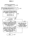
- FIG. 3 is a flow chart relating to the first embodiment and showing a bouncing suppressing control program executed by the controller of FIG. 2;
- FIG. 4 is a graph showing the braking and drive force as a function of average sprung displacement;
- FIG. 5(A) is a schematic side elevation for explaining braking and drive force control when the vehicle body is moving upwards, and FIG. 5(B) is a schematic side elevation for explaining braking and drive force control when the vehicle body is moving downwards;
- FIG. 6 is a flow chart relating to a second embodiment of the present invention and showing a ground contact load variation suppressing control program executed by the controller of FIG. 2;
- FIG. 7 is a graph showing the braking and drive force as a function of unsprung acceleration;
- FIGS. 8(A) and 8(B) are schematic side elevations for explaining braking and drive force control for the front wheels and rear wheels, respectively, of the vehicle when the wheels are moving upward, and FIGS. 8(C) and 8(D) are schematic side elevations for explaining braking and drive force control for the front wheels and rear wheels, respectively, of the vehicle when the wheels are moving downwards; and
- FIG. 9 is a graph showing the variation of ground contact load as a function of the frequency of vibrations input from a road surface for a vehicle which is equipped with in-wheel motors and a braking and drive force control apparatus according to the present invention, for a conventional vehicle, and for a vehicle which is equipped with in-wheel motors but in which ground contact load variation suppressing control is not performed.
- Below, a braking and drive force control apparatus according to a first embodiment of the present invention will be described while referring to the drawings. FIG. 1 is a schematic side view showing the righthand portion of a vehicle.
- The left and right, front and rear wheels Wfl, Wfr, Wrl, and Wrr of the vehicle are suspended on a vehicle body BD by suspensions Sfl, Sfr, Srl, and Srr (see FIG. 2). The suspensions Sfl, Sfr, Srl and Srr have the same structure on the left and right sides of the vehicle, so only the suspensions Sfr and Srr positioned on the right side of the vehicle will be explained in detail, and a detailed explanation of the suspensions Sfl and Srl positioned on the left side of the vehicle will be omitted.
- The front suspension Sfr includes an
upper arm 11 and alower arm 12. Theupper arm 11 is mounted on the vehicle body BD at itsinner ends outer end 11 c on acarrier 13 which supports the right front wheel Wfr. Thelower arm 12 is mounted on the vehicle body BD at itsinner ends carrier 13 at itsouter end 12c. - The axis of the
inner ends upper arm 11 and the axis of theinner ends lower arm 12 intersect at an intersection point O which is positioned above and towards the rear of the vehicle body with respect to the ground contact surface O of the right front wheel Wfr. This intersection point O is the instant center of the right front wheel Wfr with respect to the vehicle body BD. When, for example, a force acts on the ground contact surface Q of the right front wheel Wfr towards the front of the vehicle, a force corresponding to the forward force acts at the intersection point O in the direction of line segment OQ connecting the intersection point O and the ground contact surface Q. In contrast, when a force acts on the ground contact surface Q of the right front wheel Wfr towards the rear of the vehicle, a force corresponding to the rearward force acts at the intersection point O in the direction of line segment QO. - The rear suspension Srr includes
upper arms lower arm 16. Theupper arms inner ends outer ends carrier 17 which supports the right rear wheel Wrr. Thelower arm 16 is rotatably mounted on the vehicle body BD for rotation about an axis extending in roughly the fore and aft direction of the vehicle at itsinner end 16a, and it is rotatably mounted on thecarrier 17 at itsouter end 16b. - The axis connecting the
inner ends upper arms inner end 16a of thelower arm 16 intersect at an intersection point P which is located above and towards the front of the vehicle with respect to the ground contact surface R of the right rear wheel Wrr. Intersection point P is the instant center of the right rear wheel Wrr with respect to the vehicle body BD. When, for example, a force acts on the ground contact surface R of the right rear wheel Wrr towards the rear of the vehicle, a force corresponding to the rearwards force acts at the intersection point P in the direction of the line segment PR connecting the intersection point P and the ground contact surface R. In contrast, when a force towards the front of the vehicle acts on the ground contact surface R of the right rear wheel Wrr, a force corresponding to the forward force acts at the intersection point P in the direction of line segment RP. - As shown in FIG. 2, the unillustrated rotational shafts of electric motors 21 - 24 which are incorporated into the wheels are integrally mounted on the left and right, front and rear wheels Wfl, Wfr, Wrl, and Wrr, respectively, of the vehicle. The electric motors (in-wheel motors) 21 - 24 have internal reduction gears, and the left and right, front and rear wheels Wfl, Wfr, Wrl, and Wrr are independently driven by their rotation.
- Next, an electric control apparatus which controls the braking and drive force of the electric motors 21 - 24 will be described. This electric control apparatus includes sprung
acceleration sensors 31a - 31 d. Thesprung acceleration sensors 31 a - 31 d are mounted on the vehicle body BD in positions corresponding to the left and right, front and rear wheels Wfl, Wfr, Wrl, and Wrr. They sense the sprung acceleration Gi (i = 1 - 4) of the vehicle body BD in the upwards and downwards direction with respect to absolute space. The sprungacceleration sensors 31a - 31 d are connected to acontroller 34 through integrators 32a - 32d and 33a - 33d. - Integrators 32a - 32d integrate the signals from the sprung
acceleration sensors 31 a - 31 d indicating the sprung acceleration Gi (i = 1 - 4), and thereby convert the sprung acceleration Gi (i = 1 - 4) into sprung velocity Vi (i = 1 - 4) indicating the absolute velocity in the upwards and downwards direction of the vehicle body BD.Integrators 33a - 33d integrate the signals from integrators 32a - 32d indicating the sprung velocity Vi (i = 1 - 4) and thereby convert the sprung velocity Vi (i = 1 - 4) into sprung displacement Xi (i = 1 - 4) indicating the absolute displacement of the vehicle body BD in the upwards and downwards direction. The sprung acceleration Gi (i = 1 - 4), the sprung velocity Vi (i = 1 - 4), and the sprung displacement Xi (i = 1 - 4) are in the upwards direction when positive and are downwards when negative. The sprungacceleration sensors 31 a - 31 d, integrators 32a - 32d, andintegrators 33a - 33d function as a vehicle body upwards and downwards vibration sensing means. - The
controller 34 comprises a microcomputer having a CPU, a ROM, a RAM, and the like as principal components. Thecontroller 34 controls the operation of the electric motors 21 - 24 by executing the bouncing suppressing control program shown in FIG. 3. Thecontroller 34 is connected to the sprungacceleration sensors 31 a - 31 d as well as to anaccelerator sensor 35a, abrake sensor 35b, and drive circuits 36 - 39. Theaccelerator sensor 35a senses the amount of depression of an unillustrated accelerator pedal of the vehicle and outputs a signal indicating the sensed amount of depression. Thebrake sensor 35b senses the amount of depression of an unillustrated brake pedal of the vehicle and outputs a signal indicating the sensed amount of depression. - The drive circuits 36 - 39 receive electric power from a
battery 41 and are respectively connected tocurrent sensors 36a - 39a which sense the current flowing to the electric motors 21 - 24. In response to instructions from thecontroller 34, the drive circuits 36 - 39 control the electric motors 21 - 24 in cooperation with thecurrent sensors 36a - 39a to drive the left and right, front and rear wheels Wfl, Wfr, Wrl, and Wrr. When the vehicle body BD is not experiencing upwards and downwards vibration, thecontroller 34 controls the rotation of the electric motors 21 - 24 through the drive circuits 36 - 39 in accordance with the signals from theaccelerator sensor 35a or thebrake sensor 35b indicating the sensed amount of depression of the accelerator pedal or brake pedal so as to brake or drive the left and right, front and rear wheels Wfl, Wfr, Wrl, and Wrr with the same braking force or drive force. Instead of thecurrent sensors 36a - 39a, torque sensors which sense the braking and drive torque of the left and right, front and rear wheels Wfl, Wfr, Wrl, and Wrr may be provided. - Next, the operation of the first embodiment having the above-described structure will be described. At prescribed short time intervals, the
controller 34 repeatedly executes the bouncing suppressing control program shown in FIG. 3. The execution of this program begins in Step S10. In Step S11, values indicating the sensed sprung displacement Xi (i = 1 - 4) are input fromintegrators 33a - 33d, values indicating the sensed sprung velocity Vi (i = 1 - 4) are input from integrators 32a - 32d, and then the processing of Step S12 and onwards is performed. - In Step S12, the average sprung displacement Xave (= ΣXi/4 (i = 1 - 4)) is calculated based on the sprung displacement Xi (i = 1 - 4) input in Step S11, and the average sprung velocity Vave (= ΣVi/4 (i = 1 - 4)) is calculated based on the sprung velocity Vi (i = 1 - 4) input in Step S11. After the processing of Step S12, in Step S13, it is determined whether the absolute value |Xave| of the average sprung displacement is at least a prescribed value X0 and whether the absolute value |Vave| of the average sprung velocity is at least a prescribed value V0. The determination in Step S13 senses whether the vehicle body BD is undergoing bouncing.
- First, the case in which the vehicle is traveling straight ahead on a flat road surface will be described. In this case, the
controller 34 makes a determination of No in Step S13 and then performs the processing of Step S14. In Step S14, thecontroller 34 controls the rotation of the electric motors 21 - 24 in cooperation with the drive circuits 36 - 39 in accordance with signals from theaccelerator sensor 35a or thebrake sensor 35b so as to rotationally drive the left and right, front and rear wheels Wfl, Wfr, Wrl, and Wrr. After the processing of Step S14, the processing of the bouncing suppressing control program is temporarily ended in Step S17. - Next, the case will be described in which the vehicle is traveling on a road surface with undulations and bouncing is occurring in the vehicle body BD, i.e., a case in which the vehicle body BD is vibrating upwards and downwards in a low frequency range of around 2 Hz. In this case, in Step S13, the
controller 34 makes a determination of Yes, i.e., a determination that bouncing is occurring in the vehicle body BD, and it executes the processing from Step S15. - In Step S15, a braking and drive force table stored in the ROM of the
controller 34 is referred to, and the braking and drive force ΔF, which changes in accordance with the average sprung displacement Xave and the average sprung velocity Vave, is calculated. As shown by the solid lines in FIG. 4, for each of a plurality of representative average sprung velocities, the braking and drive force table stores a braking and drive force ΔF for the left and right front wheels Wfl and Wfr which increases nonlinearly as the average sprung displacement Xave increases, and as shown by the dashed lines in FIG. 4, for each of the plurality of representative average sprung velocities, it stores a braking and drive force ΔF for the left and right rear wheels Wrl and Wrr which decreases nonlinearly as the average sprung displacement Xave increases. - A positive value for these braking and drive forces ΔF indicates the application to the wheels of a drive force ΔF towards the front of the vehicle, and a negative value indicates the application to the wheels of a braking force ΔF towards the rear of the vehicle. For the same average sprung displacement Xave, the braking and drive forces ΔF have the same magnitude for the left and right front wheels Wfl and Wfr and the left and right rear wheels Wrl and Wrr, but they are applied in opposite directions from each other in the fore and aft direction of the vehicle. The higher the average sprung velocity, the higher the braking and drive forces ΔF are set.
- In Step S16, the
controller 34 drives and controls the electric motors 21 - 24 in accordance with the total drive force, which is the sum of the drive force during running and the braking and drive force ΔF added thereto. Specifically, when the vehicle body BD has risen, the average sprung displacement Xave is positive, so in accordance with the average sprung velocity Vave, a drive force ΔF is added to the drive force at the time of running for the left and right front wheels Wfl and Wfr, and a braking force ΔF is added to the drive force at the time of running for the left and right rear wheels Wrl and Wrr (see FIG. 4). Accordingly, as shown in FIG. 5(A), in accordance with the added braking or drive force ΔF, forces ΔF having the same magnitude but in opposite directions in the fore and aft direction of the vehicle are applied to the left and right, front and rear wheels Wfl, Wfr, Wrl, and Wrr. - As a result, in the vehicle body BD which is rising due to bouncing of the vehicle body BD, a downwards force is generated at instant center O which is determined by the suspensions Sfl and Sfr for the left and right front wheels Wfl and Wfr, and a downwards force is generated at instant center P which is determined by the suspensions Srl and Srr for the left and right rear wheels Wrl and Wrr. As a result, upwards movement of the vehicle body BD is suppressed. In this case, the sum of the forces ΔF generated in the left and right, front and rear wheels Wfl, Wfr, Wrl, and Wrr is 0 as viewed for the vehicle as a whole, so acceleration of the vehicle in the fore and aft direction is not produced, and the forces ΔF are in opposite directions for the front and rear of the vehicle, so a yawing moment is not produced in the vehicle.
- When the vehicle body is descending, the average sprung displacement Xave is negative, so in accordance with the average sprung velocity Vave, a braking force ΔF is added to the drive force at the time of running for the left and right front wheels Wfl and Wfr, and a drive force ΔF is added to the drive force at the time of running for the left and right rear wheels Wrl and Wrr (see FIG. 4). Accordingly, as shown in FIG. 5(B), forces ΔF of the same magnitude corresponding to the added braking and drive forces ΔF are applied to the left and right, front and rear wheels Wfl, Wfr, Wrl, and Wrr in opposite directions in the fore and aft direction of the vehicle.
- As a result, in a vehicle body BD which is descending due to bouncing of the vehicle body BD, an upwards force is generated at each instant center O determined by the suspensions Sfl and Sfr for the left and right front wheels Wfl and Wfr, and an upwards force is generated at each instant center P determined by the suspensions Srl and Srr for the left and right rear wheels Wrl and Wrr. As a result, downwards movement of the vehicle body BD is suppressed. In this case as well, in the same manner as when the vehicle body BD is moving upwards, the sum of the forces ΔF which are generated in the left and right, front and rear wheels Wfl, Wfr, Wrl, and Wrr is 0 as viewed for the vehicle as a whole, so acceleration of the vehicle in the fore and aft direction is not produced, and ΔF is generated in the opposite direction for the front and rear of the vehicle, so a yawing moment is not generated in the vehicle.
- After the processing of Step S16, in Step S17, the execution of the bouncing suppressing control program is temporarily ended. When bouncing of the vehicle body BD continues, the processing of Steps S15 and S16 is repeatedly performed. As a result, it is not necessary to set suspension components such as unillustrated coil springs or shock absorbers on the hard side, so ride comfort can be maintained, and running stability of the vehicle can be achieved while suppressing bouncing of the vehicle body.
- In the above-described first embodiment, the braking and drive forces ΔF applied to the left and right, front and rear wheels Wfl, Wfr, Wrl, and Wrr are calculated using a braking and drive force table which stores braking and drive forces ΔF which vary in accordance with the average sprung displacement Xave. In this case, the braking and drive force ΔF is set to a magnitude necessary to displace the average sprung displacement Xave to a target position. In the above-described first embodiment, the target position is set to a position in which the relative displacement of the vehicle body BD with respect to an unsprung member LA is 0 when the vehicle is horizontal. For example, it can be set to the vehicle height when the vehicle is starting on a flat road surface. However, the present invention is not limited to the case in which the target position is set in this manner, and as shown by dashed lines in FIG. 2, a
vehicle height sensor 42 such as a stroke sensor which senses the stroke of the vehicle body BD with respect to an unsprung member LA can be provided, and the target position can be determined based on the stroke sensed by thevehicle height sensor 42. As a result, bouncing of the vehicle BD due to displacement of the road surface can be suppressed. The present invention is also not limited to the case in which the sprung velocity and sprung displacement are calculated based on the sprung acceleration sensed by sprungacceleration sensors 31a - 31 d, and bouncing of the vehicle body BD can be determined by the stroke sensed by thevehicle height sensors 42, for example, in addition to or instead of using the sprungacceleration sensors 31 a - 31 d. - Next, a second embodiment of the present invention will be described. As shown by dashed lines in FIG. 2, a braking and drive force control apparatus for a vehicle according to this second embodiment has
unsprung acceleration sensors 43a - 43d instead of sprungacceleration sensors 31 a - 31 d. Theunsprung acceleration sensors 43a - 43d are respectively mounted on thelower arms unsprung acceleration sensors 43a - 43d function as a wheel upwards and downwards vibration sensing means. Acontroller 34 according to this second embodiment stores the ground contact load variation suppressing control program shown in FIG. 6 instead of the bouncing suppressing control program shown in FIG. 3 and repeatedly executes this program at prescribed short time intervals. Other portions of this embodiment are the same as in the above-described first embodiment. - Below, the operation of the second embodiment will be described. The
controller 34 repeatedly executes the ground contact load variation suppressing control program shown in FIG. 6 at prescribed short time intervals. This program is independently executed for each of the left and right, front and rear wheels Wfl, Wfr, Wrl, and Wrr. - The execution of this ground contact load variation suppressing control program begins in Step S20. In Step S21, sensed values indicating the unsprung acceleration Gli (i = 1 - 4) are read in from the
unsprung acceleration sensors 43a - 43d respectively, and then the processing of Step S22 and onwards is executed. - In Step S22, the unsprung acceleration Gli (i = 1 - 4) is subjected to band pass filter processing so as to obtain unsprung acceleration Gli (i = 1 - 4) in an unsprung resonant band. Next, in Step S23, it is determined whether the absolute value of the obtained unsprung acceleration Gli (i = 1 - 4) in the unsprung resonant band is at least a prescribed threshold value. Here, the case will be described in which the vehicle is traveling straight ahead on a flat road surface. In this case, none of the left and right, front and rear wheels Wfl, Wfr, Wrl, and Wrr is experiencing vibrations, so a determination of No is made in Step S23, and the processing of Step S24 is executed.
- In Step S24, in the same manner as in the processing of Step S14 in the above-described first embodiment, the
controller 34 controls the rotation of the electric motors 21 - 24 in cooperation with the drive circuits 36 - 39 in accordance with the signals from theaccelerator sensor 35a or thebrake sensor 35b so as to rotationally drive the left and right, front and rear wheels Wfl, Wfr, Wrl, and Wrr. After the processing of Step S24, the execution of the ground contact load variation suppressing control program is temporarily ended in Step S27. - Next, the case will be described in which the vehicle is traveling on a road surface having many small irregularities, and the left and right, front and rear wheels Wfl, Wfr, Wrl, and Wrr are vibrating upwards and downwards in a high frequency range of around 10 some Hz. In this case, in Step S23, the
controller 34 makes a determination of Yes, namely, a determination that the left and right, front and rear wheels Wfl, Wfr, Wrl, and Wrr are undergoing resonant vibration, and the processing from Step S25 is performed. - In Step S25, the braking and drive force ΔF, which varies in accordance with the unsprung acceleration Gli (i = 1 - 4), is calculated by referring to a braking and drive force table stored in the ROM of the
controller 34. This braking and drive force table stores the braking and drive force ΔF for the left and right front wheels Wfl and Wfr which increases nonlinearly as the unsprung acceleration Gli (i = 1 - 4) increases, as shown by the solid line in FIG. 7, and it stores the braking and drive force ΔF for the left and right rear wheels Wrl and Wrr which decreases nonlinearly as the unsprung acceleration Gli (i = 1 - 4) increases, as shown by the dashed line in FIG. 7. A positive value for the braking and drive force ΔF indicates that a drive force ΔF is applied to a wheel towards the front of the vehicle, and a negative value indicates that a braking force ΔF is applied to a wheel towards the rear of the vehicle. - In Step S26, the electric motors 21 - 24 are driven and controlled in accordance with the total drive force, which is the sum of the drive force at the time of running and the braking and drive force ΔF added thereto. Specifically, when the left front wheel Wfl is experiencing a positive unsprung acceleration Gl1 and the left front wheel Wfl is rising due to the left front wheel Wfl riding over a bump in the road surface and receiving an impact from the bump, in accordance with unsprung acceleration Gl1, a drive force ΔF is added to the drive force at the time of running for the left front wheel Wfl (see FIG. 7). For the right front wheel Wfr, in the same manner as for the left front wheel Wfl, a drive force ΔF is added to the drive force at the time of running for the right front wheel Wfr in accordance with unsprung acceleration Gl2.
- On the other hand, when the left rear wheel Wrl is experiencing a positive unsprung acceleration Gl3 and the left rear wheel Wrl is rising due to the left rear wheel Wrl riding over a bump in the road surface and receiving an impact from the bump, a braking force ΔF is added to the drive force at the time of running for the left rear wheel Wrl in accordance with unsprung acceleration G13 (see FIG. 7). For the right rear wheel Wrr as well, in the same manner as for the left rear wheel Wrl, a braking force ΔF is added to the drive force at the time of running for the right rear wheel Wrr in accordance with unsprung acceleration G14.
- When each of the wheels Wfl, Wfr, Wrl, and Wrr rides over a bump in the road surface and receives an impact from the bump, the ground contact load of each wheel Wfl, Wfr, Wrl, and Wrr increases. Accordingly, in this case, as shown in FIG. 8(A), if a drive force ΔF is applied to the left front wheel Wfl (the right front wheel Wfr), an upwards force ΔFu is generated in the left front wheel Wfl (the right front wheel Wfr) in accordance with this drive force ΔF.
- Namely, the drive force ΔF which is applied to the left front wheel Wfl (the right front wheel Wfr) has a downwards force component acting on suspension Sfl (Sfr) in the direction of the instant center O determined by suspension Sfl (Sfr) and an upwards force component ΔFu acting on the ground contact surface of the left front wheel Wfl (right front wheel Wfr). As a result of this upwards force ΔFu acting on the ground contact surface of the left front wheel Wfl (the right front wheel Wfr), the left front wheel Wfl (the right front wheel Wfr) is pushed up, so the left front wheel Wfl (the right front wheel Wfr) can move up while following the bump in the road surface. As a result, the ground contact load of the left front wheel Wfl (the right front wheel Wfr) is decreased, and the ability of the front wheels to contact the ground is improved.
- As shown in FIG. 8(B), when a braking force ΔF is applied to the left rear wheel Wrl (the right rear wheel Wrr), in the same manner as with the left front wheel Wfl (the right front wheel Wfr), an upwards force ΔFu which acts on the ground contact surface of the left rear wheel Wrl (the right rear wheel Wrr) is generated as a component of the braking force ΔF. Due to the upwards force ΔFu which acts on the ground contact surface of the left rear wheel Wrl (right rear wheel Wrr), the left rear wheel Wrl (right rear wheel Wrr) is pushed up, so the left rear wheel Wrl (right rear wheel Wrr) can move up while following the bump in the road surface. As a result, the ground contact load of the left rear wheel Wrl (right rear wheel Wrr) is decreased, and the ability of the rear wheels to contact the ground is improved.
- Next, when the left front wheel Wfl is experiencing a negative unsprung acceleration Gl1 and the left front wheel Wfl is descending due to being positioned above a depression following a bump in the road surface, a braking force ΔF is added to the drive force at the time of running for the left front wheel Wfl in accordance with unsprung acceleration Gl1 (see FIG. 7). For the right front wheel Wfr as well, in the same manner as for the left front wheel Wfl, a braking force ΔF is added to the drive force at the time of running for the right front wheel Wfr in accordance with unsprung acceleration Gl2.
- On the other hand, when the left rear wheel Wrl is experiencing a negative unsprung acceleration Gl3 and the left rear wheel Wrl is descending due to being positioned above a depression following a bump in the road surface, a drive force ΔF is added to the drive force at the time of running for the left rear wheel Wrl in accordance with unsprung acceleration Gl3 (see FIG. 7). For the right rear wheel Wrr as well, in the same manner as for the left rear wheel Wrl, a drive force ΔF is added to the drive force at the time of running for the right rear wheel Wrr in accordance with unsprung acceleration G14.
- When each of the wheels Wfl, Wfr, Wrl, and Wrr is positioned above a depression in the road surface, the area of ground contact with the road surface decreases, so the ground contact load of each of the wheels Wfl, Wfr, Wrl, and Wrr decreases. Accordingly, in this case, as shown in FIG. 8(C), when a braking force ΔF is applied to the left front wheel Wfl (right front wheel Wfr), a downwards force ΔFd is generated in the left front wheel Wfl (right front wheel Wfr) in accordance with the braking force ΔF.
- Namely, the braking force ΔF which is applied to the left front wheel Wfl (right front wheel Wfr) has an upwards force component acting on the suspension Sfl (Sfr) in the direction of the instant center O determined by suspension Sfl (Sfr) and a downwards force component ΔFd acting on the ground contact surface of the left front wheel Wfl (right front wheel Wfr). Due to the downwards force ΔFd acting on the ground contact surface of the left front wheel Wfl (right front wheel Wfr), the left front wheel Wfl (right front wheel Wfr) is pulled down, so the left front wheel Wfl (right front wheel Wfr) can move down while following the depression in the road surface. As a result, the ground contact load of the left front wheel Wfl (right front wheel Wfr) is increased, and the ability of the front wheels to contact the ground is improved.
- As shown in FIG. 8(D), when a drive force ΔF is applied to the left rear wheel Wrl (right rear wheel Wrr), in the same manner as for the left front wheel Wfl (right front wheel Wfr), a downwards force ΔFd which acts on the ground contact surface of the left rear wheel Wrl (right rear wheel Wrr) is generated as a component of the drive force ΔF. Due to this downwards force ΔFd which acts on the ground contact surface for the left rear wheel Wrl (right rear wheel Wrr), the left rear wheel Wrl (right rear wheel Wrr) is pulled down, so the left rear wheel Wrl (right rear wheel Wrr) can move down while following the depression in the road surface. As a result, the ground contact load of the left rear wheel Wrl (right rear wheel Wrr) is increased, and the ability of the rear wheels to contact the ground is improved.
- If each of the wheels Wfl, Wfr, Wrl, and Wrr is repeatedly undergoing upwards and downwards vibration, the processing of Step S25 and Step S26 is repeatedly executed, and a drive force ΔF or a braking force ΔF is applied to each wheel Wfl, Wfr, Wrl, and Wrr depending on whether the unsprung acceleration Gli (i = 1 - 4) is positive or negative. As a result, as shown in FIG. 9, a vehicle having in-wheel motors and undergoing braking and drive force control suppresses variations in ground contact load compared not only to a vehicle with in-wheel motors which do not undergo braking and drive force control but also compared to a conventional vehicle not equipped with in-wheel motors.
- In accordance with the above-described second embodiment, it is not necessary to set suspension components such as coil springs or shock absorbers on the hard side, so ride comfort is maintained, variations in ground contact load are suppressed, and driving stability of the vehicle can be obtained. It is not necessary, for example, to mount each motor on a wheel by means of a damper in order to suppress variations in ground contact load, so the effect is obtained that the structure of the vehicle does not become complicated.
- In the above-described second embodiment, the braking and drive force ΔF to be applied to the left and right, front and rear wheels Wfl, Wfr, Wrl, and Wrr is calculated using a braking and drive force table which stores braking and drive forces ΔF which vary in accordance with the unsprung acceleration Gli (i = 1 - 4). The unsprung acceleration Gli (i = 1 - 4) can be sensed in an early stage of control timing, so the time lag from when upwards and downwards vibration of each wheel Wfl, Wfr, Wrl, and Wrr occurs until a braking or drive force ΔF is applied to each wheel can be made small. However, the present invention is not limited to the case in which the braking and drive force ΔF is calculated based on the unsprung acceleration Gli (i = 1 - 4), and the braking and drive force ΔF may be calculated by sensing the unsprung velocity and/or unsprung displacement instead of or in addition to the unsprung acceleration.
- Above, first and second embodiments of the present invention and variations thereof have been described, but the present invention is not limited to the above-described embodiments, and various changes are possible while still accomplishing the object of the present invention.
- For example, in the first and second embodiments and in variations thereof, the
controller 34 stores either a bouncing suppressing control program or a ground contact load variation suppressing control program. However, thecontroller 34 may store both a bouncing suppressing control program and a ground contact load variation suppressing control program, and in a resonant range of the vehicle body BD, the bouncing suppressing control program of the above-described first embodiment may be executed, and in a resonant range of the wheels, the ground contact load variation suppressing control program of the above-described second embodiment may be executed. - In the above-described first and second embodiments and in variations thereof, the case was described in which the instant centers which are determined by the front suspensions Sfl and Sfr are located above and to the rear of the ground contact surfaces for the front wheels and in which the instant centers determined by the rear suspensions Srl and Srr are located above and forward of the ground contact surfaces for the rear wheels. However, the instant centers are not limited to these positions. For example, the instant centers determined by the front suspensions Sfl and Sfr may be located below and forward of the ground contact surfaces for the front wheels with the instant centers determined by the rear suspensions Srl and Srr being located below and to the rear of the ground contact surfaces for the rear wheels (first variation), or the instant centers determined by the front suspensions Sfl and Sfr may be located above and forward of the ground contact surfaces for the front wheels with the instant centers determined by the rear suspensions Srl and Srr being located above and to the rear of the ground contact surfaces for the rear wheels (second variation), or the instant centers determined by the front suspensions Sfl and Sfr may be located below and to the rear of the ground contact surfaces for the front wheels with the instant centers determined by the rear suspensions Srl and Srr being located below and forward of the ground contact surfaces for the rear wheels (third variation).
- In this case, in the first variation, in the same manner as in the first embodiment, when the vehicle body BD is rising, by adding a drive force ΔF to the drive force at the time of running for the front wheels and adding a braking force ΔF to the drive force at the time of running for the rear wheels, a downwards force can be generated at the instant center determined by each suspension. When the vehicle body BD is descending, by adding a braking force ΔF to the drive force at the time of running for the front wheels and adding a drive force ΔF to the drive force at the time of running for the rear wheels, an upwards force can be generated at the instant center determined by each suspension.
- In contrast, in the second and third variations, in the reverse of the first embodiment, when the vehicle body BD is rising, by adding a braking force ΔF to the drive force at the time of running for the front wheels and adding a drive force ΔF to the drive force at the time of running for the rear wheels, a downwards force can be generated at the instant center determined by each suspension. In addition, when the vehicle body BD is descending, by adding a drive force ΔF to the drive force at the time of running for the front wheels and adding a braking force ΔF to the drive force at the time of running for the rear wheels, an upwards force can be generated at the instant center determined by each suspension.
- In the above-described first variation, in the same manner as in the second embodiment, when a positive unsprung acceleration is generated in the wheels and the wheels are rising, by adding a drive force ΔF to the drive force at the time of running for the front wheels in accordance with the unsprung acceleration, an upwards force ΔFu can be applied to each of the front wheels, and by adding a braking force ΔF to the drive force at the time of running for the rear wheels, an upwards force ΔFu can be applied to each of the rear wheels. In addition, when a negative unsprung acceleration is generated in the wheels and an unsprung member LA is descending, in accordance with the unsprung acceleration, a braking force ΔF is added to the drive force at the time of running for the front wheels, whereby a downwards force ΔFd can be applied to each of the front wheels, and a drive force ΔF is added to the drive force at the time of running for the rear wheels, whereby a downwards force ΔFd can be applied to each of the rear wheels.
- In contrast, in the above-described second and third variations, in the reverse of the above-described second embodiment, when a positive unsprung acceleration is generated in the wheels and the wheels are rising, in accordance with the unsprung acceleration, a braking force ΔF is added to the drive force at the time of running for the front wheels, whereby an upwards force ΔFu can be applied to each of the front wheels, and a drive force ΔF is added to the drive force at the time of running for the rear wheels, whereby an upwards force ΔFu can be applied to each of the rear wheels. In addition, when a negative unsprung acceleration is generated in the wheels and the wheels are descending, in accordance with the unsprung acceleration, by adding a drive force ΔF to the drive force at the time of running for the front wheels, a downwards force ΔFd can be applied to each of the front wheels, and by adding a braking force ΔF to the drive force at the time of running for the rear wheels, a downwards force ΔFd can be applied to each of the rear wheels.
Claims (7)
- A braking and drive force control apparatus for a vehicle which has four actuators which independently drive four wheels which are suspended on a vehicle body by a suspension apparatus and which can independently control the braking and drive forces generated by the four actuators, comprising:a vehicle body upwards and downwards vibration sensing means which senses upwards and downwards vibration of the vehicle body; anda braking and drive force control means which produces a difference in the braking and drive forces generated by the four actuators in accordance with the sensed upwards and downwards vibration of the vehicle body to thereby apply a force to the vehicle body in a direction for suppressing the upwards and downwards vibration of the vehicle body.
- A braking and drive force control apparatus for a vehicle as claimed in claim 1, wherein the braking and drive force control means produces a difference in the braking and drive forces generated by the four actuators so as to generate forces on the front and rear wheels in opposite directions in the fore and aft direction of the vehicle to thereby generate a downwards force on the vehicle body when the vehicle body has risen and produces a difference in the braking and drive forces generated by the four actuators so as to generate forces on the front and rear wheels in opposite directions in the fore and aft direction of the vehicle to thereby generate an upwards force on the vehicle body when the vehicle body has descended.
- A braking and drive force control apparatus for a vehicle as claimed in claim 1, wherein the vehicle body upwards and downwards vibration sensing means includes a sprung acceleration sensor which senses the sprung acceleration of the vehicle body in the upwards and downwards direction with respect to absolute space and a bouncing sensing means which senses bouncing of the vehicle body based on the sprung acceleration which was sensed, and
the braking and drive force control means includes a braking and drive force calculating means which calculates the braking and drive force to be generated by the four actuators in accordance with the sensed bouncing of the vehicle body and a drive force control means which drives and controls the four actuators in accordance with the calculated braking and drive force. - A braking and drive force control apparatus for a vehicle as claimed in claim 3, wherein the bouncing sensing means includes a sprung displacement calculating means which calculates the sprung displacement of the vehicle body in the upwards and downwards direction based on the sensed sprung acceleration and senses bouncing of the vehicle body when the calculated sprung displacement is at least a prescribed value.
- A braking and drive force control apparatus for a vehicle which has four actuators which independently drive four wheels which are suspended on a vehicle body by a suspension apparatus and which can independently control the braking and drive forces generated by the four actuators, comprising:a wheel upwards and downwards vibration sensing means which senses upwards and downwards vibration of each of the wheels; anda braking and drive force control means which changes the braking and drive force generated by the actuator corresponding to each wheel in accordance with the sensed upwards and downwards vibration of the corresponding wheel and applies a force in the direction allowing upwards and downwards vibration of the corresponding wheel.
- A braking and drive force control apparatus for a vehicle as claimed in claim 5, wherein the braking and drive force control means changes the braking and drive force which is generated by the actuator corresponding to a rising wheel so as to generate an upwards force in the wheel and which changes the braking and drive force generated by the actuator corresponding to a descending wheel so as to generate a downwards force in the wheel.
- A braking and drive force control apparatus for a vehicle as claimed in claim 5, wherein the upwards and downwards vibration sensing means for each wheel senses the unsprung acceleration of the wheel in the upwards and downwards direction with respect to absolute space, and the braking and drive force control means includes a braking and drive force calculating means which calculates the braking and drive force to be generated by the actuator corresponding to each wheel in accordance with the sensed unsprung acceleration and a drive force control means which drives and controls the actuator in accordance with the calculated braking and drive force.
Applications Claiming Priority (1)
| Application Number | Priority Date | Filing Date | Title |
|---|---|---|---|
| JP2004294578A JP4471103B2 (en) | 2004-10-07 | 2004-10-07 | Vehicle braking / driving force control device |
Publications (3)
| Publication Number | Publication Date |
|---|---|
| EP1645455A2 true EP1645455A2 (en) | 2006-04-12 |
| EP1645455A3 EP1645455A3 (en) | 2014-07-30 |
| EP1645455B1 EP1645455B1 (en) | 2019-03-06 |
Family
ID=35429424
Family Applications (1)
| Application Number | Title | Priority Date | Filing Date |
|---|---|---|---|
| EP05021042.6A Ceased EP1645455B1 (en) | 2004-10-07 | 2005-09-27 | Braking and drive force control apparatus for a vehicle |
Country Status (4)
| Country | Link |
|---|---|
| US (1) | US7788011B2 (en) |
| EP (1) | EP1645455B1 (en) |
| JP (1) | JP4471103B2 (en) |
| CN (1) | CN100581856C (en) |
Cited By (3)
| Publication number | Priority date | Publication date | Assignee | Title |
|---|---|---|---|---|
| EP2810835A1 (en) * | 2013-06-04 | 2014-12-10 | Aisin Seiki Kabushiki Kaisha | Vehicle control device |
| EP2778006A4 (en) * | 2011-11-10 | 2015-12-23 | Toyota Motor Co Ltd | DEVICE FOR CONTROLLING THE BEHAVIOR OF A VEHICLE |
| CN108454630A (en) * | 2017-02-21 | 2018-08-28 | 大众汽车有限公司 | Control system, motor vehicle and correlation technique for weakening motor vehicle powertrain vibration |
Families Citing this family (34)
| Publication number | Priority date | Publication date | Assignee | Title |
|---|---|---|---|---|
| JP4887771B2 (en) * | 2005-12-12 | 2012-02-29 | トヨタ自動車株式会社 | Traveling device |
| JP4965131B2 (en) * | 2006-01-27 | 2012-07-04 | トヨタ自動車株式会社 | In-wheel motor |
| JP2007244094A (en) * | 2006-03-08 | 2007-09-20 | Honda Motor Co Ltd | Rotational torque control device for vehicle |
| US20100094495A1 (en) * | 2007-03-05 | 2010-04-15 | Yokohama National University | Pitching control device of motor vehicle and control method |
| JP4911111B2 (en) * | 2008-05-08 | 2012-04-04 | トヨタ自動車株式会社 | Vehicle control device |
| JP5343827B2 (en) * | 2009-12-02 | 2013-11-13 | 株式会社ジェイテクト | Control device for driving force distribution device |
| JP5531730B2 (en) * | 2010-03-31 | 2014-06-25 | トヨタ自動車株式会社 | Vehicle control device |
| EP2612782B1 (en) * | 2010-08-31 | 2018-09-19 | Toyota Jidosha Kabushiki Kaisha | Braking-driving force control device of vehicle |
| JP5212663B2 (en) | 2010-10-21 | 2013-06-19 | トヨタ自動車株式会社 | Vehicle braking / driving force control device |
| CN102616101B (en) * | 2011-01-28 | 2014-12-17 | 日产自动车株式会社 | Vehicle running state control device |
| JP5831041B2 (en) * | 2011-08-24 | 2015-12-09 | 日産自動車株式会社 | Vehicle behavior control apparatus and vehicle behavior control method |
| JP5650087B2 (en) * | 2011-10-11 | 2015-01-07 | トヨタ自動車株式会社 | Vehicle driving force control device |
| JP5862273B2 (en) * | 2011-12-19 | 2016-02-16 | トヨタ自動車株式会社 | Vehicle behavior control device |
| US8965609B2 (en) * | 2011-12-29 | 2015-02-24 | Kawasaki Jukogyo Kabushiki Kaisha | Electric vehicle |
| CN104080668B (en) * | 2012-01-25 | 2017-03-01 | 日产自动车株式会社 | Vehicle control device and vehicle control method |
| JP5998492B2 (en) * | 2012-01-31 | 2016-09-28 | 日産自動車株式会社 | Vehicle control device |
| JP5900601B2 (en) * | 2012-02-24 | 2016-04-06 | トヨタ自動車株式会社 | Vehicle behavior control device |
| JP5754396B2 (en) * | 2012-03-02 | 2015-07-29 | トヨタ自動車株式会社 | Vehicle braking / driving force control device |
| JP2013193717A (en) * | 2012-03-23 | 2013-09-30 | Nissan Motor Co Ltd | Control apparatus for vehicle and control method for vehicle |
| WO2014068793A1 (en) * | 2012-11-05 | 2014-05-08 | トヨタ自動車株式会社 | Steering control device |
| JP6070141B2 (en) * | 2012-12-12 | 2017-02-01 | 日産自動車株式会社 | Vehicle behavior control apparatus and vehicle behavior control method |
| JP5862636B2 (en) * | 2013-10-16 | 2016-02-16 | トヨタ自動車株式会社 | Braking / driving force control device for vehicle |
| JP6774226B2 (en) * | 2015-11-13 | 2020-10-21 | Kyb株式会社 | Suspension device |
| JP2017088060A (en) * | 2015-11-13 | 2017-05-25 | Kyb株式会社 | Suspension device |
| JP6640590B2 (en) * | 2016-02-12 | 2020-02-05 | Kyb株式会社 | Vehicle damping device |
| CN109109601A (en) * | 2018-09-10 | 2019-01-01 | 燕山大学 | Inertia regulation Active Suspensions control system and control method based on vehicle pose deviation |
| US20210283969A1 (en) * | 2020-03-12 | 2021-09-16 | Mitsubishi Electric Research Laboratories, Inc. | Method and System for Achieving Active Suspension using Independently Actuated Wheels |
| EP4400353A4 (en) * | 2021-09-06 | 2024-11-13 | Nissan Motor Co., Ltd. | DRIVE FORCE CONTROL METHOD AND DRIVE FORCE CONTROL DEVICE |
| JP7846545B2 (en) * | 2022-03-16 | 2026-04-15 | 株式会社Subaru | Vehicle turning behavior control system |
| DE102022108679A1 (en) * | 2022-04-11 | 2023-10-12 | Dr. Ing. H.C. F. Porsche Aktiengesellschaft | Method for reducing vibration of a vehicle body of an electric vehicle by means of its electric motor |
| AT526404B1 (en) * | 2022-07-26 | 2024-09-15 | E More Ag | vehicle |
| CN118722108A (en) * | 2023-03-31 | 2024-10-01 | 比亚迪股份有限公司 | Vehicle take-off control method, device, active suspension and vehicle |
| JPWO2025120947A1 (en) * | 2023-12-08 | 2025-06-12 | ||
| JP2026055012A (en) * | 2024-09-17 | 2026-03-30 | Astemo株式会社 | Vehicle motion control device, vehicle motion control method |
Family Cites Families (19)
| Publication number | Priority date | Publication date | Assignee | Title |
|---|---|---|---|---|
| JP2655684B2 (en) * | 1988-07-01 | 1997-09-24 | アイシン・エィ・ダブリュ株式会社 | Vehicle steering system |
| JP2984724B2 (en) | 1989-03-31 | 1999-11-29 | 株式会社 四国総合研究所 | Electric car |
| JP3280392B2 (en) | 1991-04-01 | 2002-05-13 | アイシン・エィ・ダブリュ株式会社 | Driving force control device for electric vehicle |
| DE19615737A1 (en) * | 1996-04-20 | 1997-10-16 | Daimler Benz Ag | Active suspension system |
| JP3451869B2 (en) | 1997-01-21 | 2003-09-29 | トヨタ自動車株式会社 | Drive control device for electric vehicles |
| JP3451912B2 (en) | 1997-12-18 | 2003-09-29 | トヨタ自動車株式会社 | Drive control device for electric vehicles |
| US6424907B1 (en) * | 1998-07-17 | 2002-07-23 | Continental Teves Ag & Co., Ohg | Method and device for determining and detecting the overturning hazard of a vehicle |
| JP2000283996A (en) * | 1999-03-29 | 2000-10-13 | Unisia Jecs Corp | Vertical acceleration detection device for vehicle |
| EP1147928B1 (en) * | 2000-04-17 | 2005-09-21 | Robert Bosch GmbH | Apparatus and method for determining vehicle operating and dynamic parameters |
| US6356188B1 (en) * | 2000-09-25 | 2002-03-12 | Ford Global Technologies, Inc. | Wheel lift identification for an automotive vehicle |
| JP2002301939A (en) | 2001-04-03 | 2002-10-15 | Fuji Heavy Ind Ltd | Hybrid vehicle drive system |
| JP3642041B2 (en) * | 2001-06-26 | 2005-04-27 | 日産自動車株式会社 | Driving force control device for four-wheel drive vehicle |
| WO2003095261A1 (en) * | 2002-05-07 | 2003-11-20 | Kabushiki Kaisha Bridgestone | Method and device for controlling vehicle |
| US20040149500A1 (en) * | 2003-02-05 | 2004-08-05 | Chernoff Adrian B. | Pre-engineered frame portion and method of use therefor |
| US6909959B2 (en) * | 2003-03-07 | 2005-06-21 | Stephen James Hallowell | Torque distribution systems and methods for wheeled vehicles |
| JP2005119548A (en) | 2003-10-17 | 2005-05-12 | Nissan Motor Co Ltd | Electric vehicle suspension system |
| DE10358335B3 (en) * | 2003-12-12 | 2005-05-25 | Siemens Ag | Arrangement for determining dynamic axle loads and/or wheel loads of wheeled vehicle has evaluation device combined with measurement device to use linear accelerations, rotation rates to determine at least one axle load and/or wheel load |
| JP4172391B2 (en) * | 2003-12-24 | 2008-10-29 | 株式会社デンソー | Vehicle integrated control system and program |
| US6904351B1 (en) * | 2004-03-17 | 2005-06-07 | Delphi Technologies, Inc. | Operating a vehicle control system |
-
2004
- 2004-10-07 JP JP2004294578A patent/JP4471103B2/en not_active Expired - Fee Related
-
2005
- 2005-09-26 US US11/234,206 patent/US7788011B2/en active Active
- 2005-09-27 EP EP05021042.6A patent/EP1645455B1/en not_active Ceased
- 2005-10-08 CN CN200510108243A patent/CN100581856C/en not_active Expired - Fee Related
Cited By (4)
| Publication number | Priority date | Publication date | Assignee | Title |
|---|---|---|---|---|
| EP2778006A4 (en) * | 2011-11-10 | 2015-12-23 | Toyota Motor Co Ltd | DEVICE FOR CONTROLLING THE BEHAVIOR OF A VEHICLE |
| EP2810835A1 (en) * | 2013-06-04 | 2014-12-10 | Aisin Seiki Kabushiki Kaisha | Vehicle control device |
| US9139062B2 (en) | 2013-06-04 | 2015-09-22 | Aisin Seiki Kabushiki Kaisha | Vehicle control device |
| CN108454630A (en) * | 2017-02-21 | 2018-08-28 | 大众汽车有限公司 | Control system, motor vehicle and correlation technique for weakening motor vehicle powertrain vibration |
Also Published As
| Publication number | Publication date |
|---|---|
| CN100581856C (en) | 2010-01-20 |
| JP2006109642A (en) | 2006-04-20 |
| CN1769083A (en) | 2006-05-10 |
| JP4471103B2 (en) | 2010-06-02 |
| EP1645455B1 (en) | 2019-03-06 |
| US20060076740A1 (en) | 2006-04-13 |
| EP1645455A3 (en) | 2014-07-30 |
| US7788011B2 (en) | 2010-08-31 |
Similar Documents
| Publication | Publication Date | Title |
|---|---|---|
| US7788011B2 (en) | Braking and drive force control apparatus for a vehicle | |
| US12251974B2 (en) | Roll vibration damping control system for vehicle and target roll moment computing method therefor | |
| US8972108B2 (en) | Method and apparatus for controlling a semi-active suspension system for motorcycles | |
| EP2641759A1 (en) | Vehicle control apparatus | |
| JP4333767B2 (en) | Vehicle control device | |
| CN111137096B (en) | Control system for variable damping force damper | |
| US8874314B2 (en) | Vehicle damping control apparatus | |
| EP2829424A1 (en) | Vehicle control device and vehicle control method | |
| US10005457B2 (en) | Driving force control device for a vehicle | |
| US20170028983A1 (en) | Electric vehicle | |
| US12441148B2 (en) | Controller, vehicle, and control method | |
| JP7501491B2 (en) | Vehicle suspension control device and vehicle suspension control method | |
| CN107444052A (en) | Vehicle damping force control device | |
| JP2009073239A (en) | Suspension control device | |
| CN112572086A (en) | Vehicle, control method of vehicle suspension and related equipment | |
| JP4797586B2 (en) | Vehicle braking / driving force control device | |
| JP2022125573A (en) | Suspension control device | |
| US12466230B2 (en) | Vehicle behavior control device and vehicle behavior control method | |
| US12403742B2 (en) | Vehicle behavior control device | |
| JP7831133B2 (en) | Vehicle control system | |
| JP5571510B2 (en) | Suspension control device | |
| JP4577149B2 (en) | Vehicle control device |
Legal Events
| Date | Code | Title | Description |
|---|---|---|---|
| PUAI | Public reference made under article 153(3) epc to a published international application that has entered the european phase |
Free format text: ORIGINAL CODE: 0009012 |
|
| 17P | Request for examination filed |
Effective date: 20051026 |
|
| AK | Designated contracting states |
Kind code of ref document: A2 Designated state(s): AT BE BG CH CY CZ DE DK EE ES FI FR GB GR HU IE IS IT LI LT LU LV MC NL PL PT RO SE SI SK TR |
|
| AX | Request for extension of the european patent |
Extension state: AL BA HR MK YU |
|
| RAP1 | Party data changed (applicant data changed or rights of an application transferred) |
Owner name: TOYOTA JIDOSHA KABUSHIKI KAISHA |
|
| PUAL | Search report despatched |
Free format text: ORIGINAL CODE: 0009013 |
|
| AK | Designated contracting states |
Kind code of ref document: A3 Designated state(s): AT BE BG CH CY CZ DE DK EE ES FI FR GB GR HU IE IS IT LI LT LU LV MC NL PL PT RO SE SI SK TR |
|
| AX | Request for extension of the european patent |
Extension state: AL BA HR MK YU |
|
| RIC1 | Information provided on ipc code assigned before grant |
Ipc: B60W 30/20 20060101ALI20140626BHEP Ipc: B60L 7/00 20060101AFI20140626BHEP Ipc: B60L 15/20 20060101ALN20140626BHEP Ipc: B60W 10/08 20060101ALI20140626BHEP Ipc: B60K 6/52 20071001ALI20140626BHEP |
|
| AKX | Designation fees paid |
Designated state(s): DE FR GB |
|
| AXX | Extension fees paid |
Extension state: YU Extension state: MK Extension state: AL Extension state: BA Extension state: HR |
|
| RIC1 | Information provided on ipc code assigned before grant |
Ipc: B60W 30/20 20060101ALI20180727BHEP Ipc: B60G 3/20 20060101ALI20180727BHEP Ipc: B60L 7/00 20060101AFI20180727BHEP Ipc: B60G 17/0195 20060101ALI20180727BHEP Ipc: B60L 15/20 20060101ALN20180727BHEP Ipc: B60K 6/52 20071001ALI20180727BHEP Ipc: B60W 10/08 20060101ALI20180727BHEP |
|
| GRAP | Despatch of communication of intention to grant a patent |
Free format text: ORIGINAL CODE: EPIDOSNIGR1 |
|
| RIC1 | Information provided on ipc code assigned before grant |
Ipc: B60W 10/08 20060101ALI20180905BHEP Ipc: B60K 6/52 20071001ALI20180905BHEP Ipc: B60L 15/20 20060101ALN20180905BHEP Ipc: B60G 3/20 20060101ALI20180905BHEP Ipc: B60G 17/0195 20060101ALI20180905BHEP Ipc: B60W 30/20 20060101ALI20180905BHEP Ipc: B60L 7/00 20060101AFI20180905BHEP |
|
| INTG | Intention to grant announced |
Effective date: 20180925 |
|
| GRAS | Grant fee paid |
Free format text: ORIGINAL CODE: EPIDOSNIGR3 |
|
| GRAA | (expected) grant |
Free format text: ORIGINAL CODE: 0009210 |
|
| RIC1 | Information provided on ipc code assigned before grant |
Ipc: B60L 15/20 20060101ALN20180905BHEP Ipc: B60K 6/52 20071001ALI20180905BHEP Ipc: B60G 17/0195 20060101ALI20180905BHEP Ipc: B60G 3/20 20060101ALI20180905BHEP Ipc: B60W 10/08 20060101ALI20180905BHEP Ipc: B60L 7/00 20060101AFI20180905BHEP Ipc: B60W 30/20 20060101ALI20180905BHEP |
|
| AK | Designated contracting states |
Kind code of ref document: B1 Designated state(s): DE FR GB |
|
| REG | Reference to a national code |
Ref country code: GB Ref legal event code: FG4D |
|
| RIN1 | Information on inventor provided before grant (corrected) |
Inventor name: SUGIYAMA, MIZUHO |
|
| REG | Reference to a national code |
Ref country code: DE Ref legal event code: R096 Ref document number: 602005055460 Country of ref document: DE |
|
| REG | Reference to a national code |
Ref country code: DE Ref legal event code: R084 Ref document number: 602005055460 Country of ref document: DE |
|
| REG | Reference to a national code |
Ref country code: DE Ref legal event code: R097 Ref document number: 602005055460 Country of ref document: DE |
|
| PLBE | No opposition filed within time limit |
Free format text: ORIGINAL CODE: 0009261 |
|
| STAA | Information on the status of an ep patent application or granted ep patent |
Free format text: STATUS: NO OPPOSITION FILED WITHIN TIME LIMIT |
|
| 26N | No opposition filed |
Effective date: 20191209 |
|
| GBPC | Gb: european patent ceased through non-payment of renewal fee |
Effective date: 20190927 |
|
| PG25 | Lapsed in a contracting state [announced via postgrant information from national office to epo] |
Ref country code: FR Free format text: LAPSE BECAUSE OF NON-PAYMENT OF DUE FEES Effective date: 20190930 Ref country code: GB Free format text: LAPSE BECAUSE OF NON-PAYMENT OF DUE FEES Effective date: 20190927 |
|
| PGFP | Annual fee paid to national office [announced via postgrant information from national office to epo] |
Ref country code: DE Payment date: 20210818 Year of fee payment: 17 |
|
| REG | Reference to a national code |
Ref country code: DE Ref legal event code: R119 Ref document number: 602005055460 Country of ref document: DE |
|
| PG25 | Lapsed in a contracting state [announced via postgrant information from national office to epo] |
Ref country code: DE Free format text: LAPSE BECAUSE OF NON-PAYMENT OF DUE FEES Effective date: 20230401 |