EP1645400B1 - Verfahren zum Starten und Stoppen einer kontinuierlich arbeitenden Thermoformmaschine mit einer Heizstation - Google Patents
Verfahren zum Starten und Stoppen einer kontinuierlich arbeitenden Thermoformmaschine mit einer Heizstation Download PDFInfo
- Publication number
- EP1645400B1 EP1645400B1 EP05014401A EP05014401A EP1645400B1 EP 1645400 B1 EP1645400 B1 EP 1645400B1 EP 05014401 A EP05014401 A EP 05014401A EP 05014401 A EP05014401 A EP 05014401A EP 1645400 B1 EP1645400 B1 EP 1645400B1
- Authority
- EP
- European Patent Office
- Prior art keywords
- heating station
- forming sheet
- heating
- thermoforming machine
- shield plate
- Prior art date
- Legal status (The legal status is an assumption and is not a legal conclusion. Google has not performed a legal analysis and makes no representation as to the accuracy of the status listed.)
- Expired - Lifetime
Links
Images


Classifications
-
- B—PERFORMING OPERATIONS; TRANSPORTING
- B29—WORKING OF PLASTICS; WORKING OF SUBSTANCES IN A PLASTIC STATE IN GENERAL
- B29C—SHAPING OR JOINING OF PLASTICS; SHAPING OF MATERIAL IN A PLASTIC STATE, NOT OTHERWISE PROVIDED FOR; AFTER-TREATMENT OF THE SHAPED PRODUCTS, e.g. REPAIRING
- B29C51/00—Shaping by thermoforming, i.e. shaping sheets or sheet like preforms after heating, e.g. shaping sheets in matched moulds or by deep-drawing; Apparatus therefor
- B29C51/26—Component parts, details or accessories; Auxiliary operations
- B29C51/42—Heating or cooling
- B29C51/421—Heating or cooling of preforms, specially adapted for thermoforming
-
- B—PERFORMING OPERATIONS; TRANSPORTING
- B29—WORKING OF PLASTICS; WORKING OF SUBSTANCES IN A PLASTIC STATE IN GENERAL
- B29C—SHAPING OR JOINING OF PLASTICS; SHAPING OF MATERIAL IN A PLASTIC STATE, NOT OTHERWISE PROVIDED FOR; AFTER-TREATMENT OF THE SHAPED PRODUCTS, e.g. REPAIRING
- B29C35/00—Heating, cooling or curing, e.g. crosslinking or vulcanising; Apparatus therefor
- B29C35/02—Heating or curing, e.g. crosslinking or vulcanizing during moulding, e.g. in a mould
- B29C35/08—Heating or curing, e.g. crosslinking or vulcanizing during moulding, e.g. in a mould by wave energy or particle radiation
- B29C35/0805—Heating or curing, e.g. crosslinking or vulcanizing during moulding, e.g. in a mould by wave energy or particle radiation using electromagnetic radiation
- B29C2035/0822—Heating or curing, e.g. crosslinking or vulcanizing during moulding, e.g. in a mould by wave energy or particle radiation using electromagnetic radiation using IR radiation
-
- Y—GENERAL TAGGING OF NEW TECHNOLOGICAL DEVELOPMENTS; GENERAL TAGGING OF CROSS-SECTIONAL TECHNOLOGIES SPANNING OVER SEVERAL SECTIONS OF THE IPC; TECHNICAL SUBJECTS COVERED BY FORMER USPC CROSS-REFERENCE ART COLLECTIONS [XRACs] AND DIGESTS
- Y10—TECHNICAL SUBJECTS COVERED BY FORMER USPC
- Y10T—TECHNICAL SUBJECTS COVERED BY FORMER US CLASSIFICATION
- Y10T29/00—Metal working
- Y10T29/30—Foil or other thin sheet-metal making or treating
-
- Y—GENERAL TAGGING OF NEW TECHNOLOGICAL DEVELOPMENTS; GENERAL TAGGING OF CROSS-SECTIONAL TECHNOLOGIES SPANNING OVER SEVERAL SECTIONS OF THE IPC; TECHNICAL SUBJECTS COVERED BY FORMER USPC CROSS-REFERENCE ART COLLECTIONS [XRACs] AND DIGESTS
- Y10—TECHNICAL SUBJECTS COVERED BY FORMER USPC
- Y10T—TECHNICAL SUBJECTS COVERED BY FORMER US CLASSIFICATION
- Y10T29/00—Metal working
- Y10T29/30—Foil or other thin sheet-metal making or treating
- Y10T29/301—Method
Definitions
- the invention relates to a method for starting in particular a continuous thermoforming machine with a heating station, in which a shielding plate between the heat source and the forming film is adjusted at a standstill, determines the residence time of the forming film in normal operation at a constant feed rate in the heating station and the acceleration of the Forming film is determined from standstill until reaching the constant feed rate, and in which the acceleration profile of opposite to the feed direction of the forming film removed from the heating station shielding plate is determined so that the local no longer shaded by the shielding plate Form foil areas are promoted in the heating station in a transfer time corresponding to the residence time of the front in the conveying direction edge of the shielding plate to the end of the heating station.
- the invention further relates to a method for stopping the thermoforming machine.
- Thermoforming machines are known from the prior art, are supplied with the forming sheets of a forming station, which serves to form wells in the film, which are subsequently filled in a filling station, sealed in a sealing station with a sealing film.
- the forming station is usually preceded by a heating station, in which the forming film is heated to the temperature required for the formation of the wells in the forming station.
- the heating can be done contact by means of hot plates or contactless by spaced from the mold film in the heating station heating elements whose heating effect can be stopped by an insertable between the heating elements and the mold film shielding.
- thermoforming machine which operates in cycles, so that the mold film is heated in sections in the heating station and this section is transferred in the next cycle for further processing in the forming station.
- the starting and stopping of the cyclically operated thermoforming machine is characterized in that in the change of the feed of the molding foil preceding clock the shield is removed from the heating station or introduced into the heating station, so that in particular when starting the thermoforming machine, the Formfolien Schemee in the Heating station heated for one tact and can be processed in the usual way in the forming station.
- DE 198 50 143 A1 discloses a device for connecting two bodies, namely a pressure-sensitive adhesive layer on a sealing profile. The two bodies are heated to this with NIR lamps, the heating is subsequently controlled by pyrometer.
- the DE 198 50 143 A1 also discloses the indication that the NIR radiation can be started or stopped within fractions of a second by using apertures, but this citation does not contain any indication, as in the case of continuously advancing bodies to prevent waste, proper heating and reaching the processing temperature are also more prolonged Ensured areas when starting the device can be.
- the invention is therefore based on the object of specifying a method for starting a thermoforming machine can be reduced with the waste of thermoforming film or even completely avoided. It is also an object to provide a method for stopping a thermoforming machine by which initial conditions defined for subsequent starting can be provided.
- the starting part of the problem is solved by the method mentioned, which is characterized by the advantages that when starting the feed of the thermoforming machine in the forming film, a temperature jump is generated at the front in the feed direction, downstream edge of the heating station, so that the entire mold film area lying in the heating station reaches the film temperature required for further processing. There is a minimization of the film waste before lying on the between the end of the heating station and the beginning of the molding station areas and the further production after a stop of the thermoforming machine can be resumed faster. At a start of the thermoforming machine is ensured for the present in the heating station Formfolienabitese that they can be heated by the heat source the full residence time in the heating station and so safely reach the processing temperature.
- thermoforming machine it is necessary if, when starting the thermoforming machine, the beginning of the adjustment of the shielding plate by a dwell time before the start of the Feed of the thermoforming film is because so the heating, in particular the placed at the downstream end of the heating station molded film sections is guaranteed regardless of the extent of the heating station.
- a plurality of adjacent NIR radiators in the conveying direction of the forming film are used as heat sources, which effect the heating of the thermoforming foil in a contactless manner substantially by thermal radiation. It is furthermore provided that the heat output of the NIR radiators is reduced when the thermoforming machine is at a standstill so as to avoid heating up the shielding plate or to save a complex cooling device for the shielding plate.
- the heat output of the NIR radiator is increased so early when starting the thermoforming machine, that at the beginning of the feed of the mold film, the heating power of the continuous operation is reached. It is even more advantageous if the heat output of the NIR radiator is increased so early on starting the thermoforming machine that at the beginning of the adjustment of the shielding plate, the heating power of continuous operation is reached, as there is already a constant heating power of the NIR radiator, when the shield plate is moved against the feed direction of the thermoforming film from the heating station and not because of a reduced heating power, the transfer time must be increased in order to introduce the required amount of heat in the mold film.
- the process step is provided that measured at least at the start of the thermoforming machine by means of a heating station downstream temperature sensor, the temperature of the thermoforming film and used as a controlled variable in a control loop for the residence time of the thermoforming film in the heating station or degree of heating becomes.
- a pyrometer is used as the temperature sensor for non-contact measurement of the temperature.
- the stopping part of the object is achieved by a method for stopping, in particular, a continuously operating thermoforming machine with a heating station, in which a shielding plate between the heat source and the forming film is adjusted for standstill in the conveying direction of the forming film, wherein the front edge in the conveying direction the shielding plate is synchronized with the mold film area coming to rest at the end of the heating station and moved and braked in synchrony by the heating station.
- This method ensures that when the thermoforming machine is at a standstill, all the already heated mold film can be processed and the mold film is only decelerated when the last molded film section to be passed has left the heating station.
- the front edge of the shielding plate in the conveying direction is exactly to the line of the forming film synchronized, which later forms the end of the forming film section in the heating station.
- the deceleration of the molding film is started only when the last heated and to be processed forming film section has left the heating station, so that the heated in the heating station Formfolienabête can be processed without modification of the usual procedure.
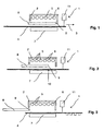
- heating station 1 is schematically shown, having a housing 2, in which above a in the direction of arrow 3, the heating station 1 continuous forming film 4, a plurality of NIR radiator 5 as heat sources 6 are arranged. On the opposite side of the mold film 4 of the heat sources 6, a counter-reflector 7 is arranged stationary.
- a Shield plate 8 arranged adjustable, which can be adjusted against the feed direction 3 of the forming film 4 from the heating station 1 by means of a regulated drive.
- Fig. 1 shows the state of the heating station 1 during a standstill of the thermoforming machine, in which the mold film 4 is protected by the shield plate 8 against heating by the heat sources 6, to which additionally the heating power of the NIR radiator 5 is reduced.
- Fig. 3 shows a snapshot of the state of the heating station 1 during normal operation, in which the mold film 4 is advanced continuously at a constant feed rate, so that an arbitrary Formfolien Scheme for resulting from the length of the heating station 1 and the constant feed rate dwell time in the heating station remains and during the dwell time D is supplied by the constant heat output working NIR radiator 5, the amount of heat required to heat the Formfolien Scheme from the initial temperature when entering the heating station 1 to the required for further processing mold temperature.
- the acceleration profile of the mold film 4 is determined from standstill until reaching the constant feed rate.
- the acceleration profile of the opposite of the feed direction of the forming film 4 removed from the heating station 1 shielding 8 is determined so that the local no longer from the shielding. 8 shaded mold film areas in the heating station 1 in a transfer time corresponding to the dwell time D from the front in the conveying direction edge 9 of the shielding plate 8 is conveyed to the end of the heating station 1.
- the required transfer time can be easily provided by starting the adjustment of the shielding plate 8 by a dwell time D before starting the feeding of the forming film 4 when starting the thermoforming machine.
- the heating power of the NIR radiator 5 is again raised to the normal value before the start of the feed of the mold film 4 and that expediently so early that at the beginning of the adjustment of the shielding plate 8, the heating power of the continuous operation is reached, ie not in the transfer time more of the shielding plate 8 shaded mold film sections, the full, constant heating power is available and thus there is no variation in the amount of heat supplied during the transfer time.
- the theoretically determined acceleration profile of the shielding plate 8 is controlled by means of a downstream of the heating station 1 temperature sensor, namely a pyrometer 11, with which the temperature of the mold film 4 is measured and used as a controlled variable in a control loop for the residence time of the mold film 4 in the heating station 1.
- FIG. 6 shows the path traveled by the forming film 4 as a function of time and the resulting position of the shielding plate 8.
- the dwell time D is moved to the right on the time axis and the vertical distance to the film starting curve is determined after the dwell time D. This distance corresponds to the opening of the shielding plate 8 at time T, so that the movement of the shielding plate 8 can be derived from the acceleration curve of the forming film 4 theoretically.
- the braking of the mold film 4 takes place only when the last heated and processed film section has left the heating station 1, wherein further in the conveying direction front edge 9 of the shield plate 8 with the at the end the heating station 1 coming to rest form film section synchronized and synchronized by the heating station 1 is moved and braked in the heating station 1. Since for normal operation is only required that the shield plate 8 is completely adjusted from the heating station 1, but the position of the shield 8 outside the heating station 1 in normal operation is arbitrary, there is also the possibility of the shield 8 outside the heating station 1 with the forming film section to synchronize and the shield plate 8 already synchronized with the Formfolienabites enter and slow down in the heating station 1.
Landscapes
- Engineering & Computer Science (AREA)
- Mechanical Engineering (AREA)
- Blow-Moulding Or Thermoforming Of Plastics Or The Like (AREA)
- Injection Moulding Of Plastics Or The Like (AREA)
- Heating, Cooling, Or Curing Plastics Or The Like In General (AREA)
- Moulds For Moulding Plastics Or The Like (AREA)
Description
- Die Erfindung ist ein Verfahren zum Starten insbesondere einer kontinuierlich arbeitenden Thermoformmaschine mit einer Heizstation, in der im Stillstand eine Abschirmplatte zwischen die Wärmequelle und die Formfolie verstellt ist, bei dem die Verweildauer der Formfolie im Normalbetrieb mit konstanter Vorschubgeschwindigkeit in der Heizstation bestimmt und der Beschleunigungsverlauf der Formfolie aus dem Stillstand bis zum Erreichen der konstanten Vorschubgeschwindigkeit festgelegt wird, und bei dem der Beschleunigungsverlauf der entgegen der Vorschubrichtung der Formfolie aus der Heizstation entfernten Abschirmplatte so bestimmt wird, daß die lokal nicht mehr von der Abschirmplatte abgeschatteten Formfolienbereiche in der Heizstation in einer der Verweildauer entsprechenden Transferzeit von dem in Förderrichtung vorderen Rand der Abschirmplatte bis zum Ende der Heizstation gefördert werden. Gegenstand der Erfindung ist weiterhin ein Verfahren zum Stoppen der Thermoformmaschine.
- Aus dem Stand der Technik sind Thermoformmaschinen bekannt, mit der Formfolien einer Formstation zugeführt werden, die zum Ausbilden von Näpfen in der Folie dient, die nachfolgend in einer Füllstation befüllt, in einer Siegelstation mit einer Siegelfolie verschlossen werden. Der Formstation ist in der Regel eine Heizstation vorgelagert, in der die Formfolie auf die für die Ausbildung der Näpfe in der Formstation erforderliche Temperatur erwärmt wird. Die Erwärmung kann dabei kontaktbehaftet mittels Heizplatten erfolgen oder kontaktlos durch mit Abstand zu der Formfolie in der Heizstation angeordnete Heizelemente, deren Heizwirkung durch eine zwischen die Heizelemente und die Formfolie einführbare Abschirmplatte gestoppt werden kann. In
DE 27 45 422 A1 undUS 4209957 sind Verfahren zum Ingangsetzen und Stillsetzen einer Thermoformmaschine beschrieben, die taktweise arbeitet, so daß die Formfolie abschnittsweise in der Heizstation erwärmt und dieser Abschnitt im nächsten Takt zur weiteren Verarbeitung in die Formstation überführt wird. Im wesentlichen erfolgt das Starten und Stoppen der taktweise betriebenen Thermoformmaschine dadurch, daß in dem der Änderung des Vorschubs der Formfolie vorgehenden Takt die Abschirmplatte aus der Heizstation entfernt beziehungsweise in die Heizstation eingebracht wird, so daß insbesondere beim Starten der Thermoformmaschine die Formfolienbereiche in der Heizstation einen Takt lang aufgeheizt und nachfolgend in üblicher Weise in der Formstation verarbeitet werden können. - Dieses Verfahren ist bei einer kontinuierlich arbeitenden Thermoformmaschine aber nicht einsetzbar, eben weil eine Taktung fehlt und die in der Heizstation befindlichen Formfolienbereiche mit dem einsetzenden Vorschub kontinuierlich aus der Heizstation entfernt werden. Unzureichend erwärmte Formfolienbereiche lassen sich jedoch nicht ordnungsgemäß weiterverarbeiten, so daß bei einer kontinuierlich arbeitenden Thermoformmaschine beim Starten Abfall produziert wird. Problematisch ist auch das Stoppen einer kontinuierlich arbeitenden Thermoformmaschine, da die in die Heizstation eingeführten Formfolienbereiche noch erwärmt werden und keine definierte Ausgangstemperatur garantiert beziehungsweise vorausgesetzt werden kann für einen nachfolgenden Start der Thermoformmaschine.
- In der
DE 198 50 143 A1 ist eine Vorrichtung zum Verbinden zweier Körper offenbart, nämlich einer Haftklebstoffschicht auf einem Dichtungsprofil. Die beiden Körper werden dazu mit NIR-Strahlern erwärmt, wobei die Erwärmung nachfolgend durch Pyrometer kontrolliert wird. DieDE 198 50 143 A1 offenbart auch den Hinweis, daß die NIR-Strahlung innerhalb von Sekundenbruchteilen durch Einsatz von Blenden begonnen oder abgebrochen werden kann, jedoch enthält diese Entgegenhaltung keinen Hinweis, wie bei kontinuierlich vorgeschobenen Körpern zur Vermeidung von Abfall die ordnungsgemäße Erwärmung und das Erreichen der Verarbeitungstemperatur auch länger ausgedehnter Bereiche beim Starten der Vorrichtung sichergestellt werden kann. - Der Erfindung liegt daher die Aufgabe zugrunde, ein Verfahren zum Starten einer Thermoformmaschine anzugeben, mit dem Abfall von Thermoformfolie reduziert oder sogar vollständig vermieden werden kann. Aufgabe ist es weiterhin, ein Verfahren zum Stoppen einer Thermoformmaschine anzugeben, durch das für das nachfolgende Starten definierte Anfangsbedingungen bereitgestellt werden können.
- Der das Starten betreffende Teil der Aufgabe wird durch das eingangs genannte Verfahren gelöst, das sich durch die Vorteile auszeichnet, daß beim Starten des Vorschubs der Thermoformmaschine in der Formfolie ein Temperatursprung erzeugt wird an dem in Vorschubrichtung vorderen, stromab liegenden Rand der Heizstation, so daß der gesamte in der Heizstation liegende Formfolienbereich die zur weiteren Verarbeitung erforderliche Folientemperatur erreicht. Es liegt eine Minimierung des Folienabfalls vor auf die zwischen dem Ende der Heizstation und dem Anfang der Formstation liegenden Bereiche und die weitere Produktion nach einem Stopp der Thermoformmaschine kann schneller wieder aufgenommen werden. Bei einem Start der Thermoformmaschine wird für die in der Heizstation befindlichen Formfolienabschnitte sichergestellt, daß diese die volle Verweildauer in der Heizstation durch die Wärmequelle erwärmt werden können und so sicher die Verarbeitungstemperatur erreichen.
- Notwendig ist es, wenn beim Starten der Thermoformmaschine der Beginn der Verstellung der Abschirmplatte um eine Verweildauer vor dem Beginn des Vorschubs der Thermoformfolie liegt, da so auch die Erwärmung insbesondere die am stromab liegenden Ende der Heizstation platzierten Formfolienabschnitte unabhängig von der Ausdehnung der Heizstation gewährleistet ist.
- Um eine möglichst gleichmäßige Erwärmung über die gesamte Ausdehnung der Heizstation in Förderrichtung zu gewährleisten, werden als Wärmequellen eine Mehrzahl in Förderrichtung der Formfolie benachbarter NIR-Strahler eingesetzt, die berührungslos im wesentlichen durch Wärmestrahlung die Erwärmung der Thermoformfolie bewirken. Vorgesehen ist weiterhin, daß die Heizleistung der NIR-Strahler im Stillstand der Thermoformmaschine reduziert wird, um so ein Aufheizen der Abschirmplatte zu vermeiden beziehungsweise eine aufwendige Kühleinrichtung für die Abschirmplatte einzusparen.
- Dann ist im Rahmen der Erfindung vorgesehen, daß die Heizleistung der NIR-Strahler beim Starten der Thermoformmaschine so frühzeitig erhöht wird, daß beim Beginn des Vorschubs der Formfolie die Heizleistung des Dauerbetriebs erreicht ist. Noch vorteilhafter ist es, wenn die Heizleistung der NIR-Strahler beim Starten der Thermoformmaschine so frühzeitig erhöht wird, daß bei Beginn der Verstellung der Abschirmplatte die Heizleistung des Dauerbetriebs erreicht ist, da so bereits eine konstante Heizleistung der NIR-Strahler vorliegt, wenn die Abschirmplatte entgegen der Vorschubrichtung der Thermoformfolie aus der Heizstation verschoben wird und nicht wegen einer reduzierten Heizleistung die Transferzeit erhöht werden muß, um die erforderliche Wärmemenge in die Formfolie einzubringen.
- Da bei der Verstellung der Abschirmplatte aus der Heizstation die Abschattung der NIR-Strahler variiert und darüber hinaus die NIR-Strahler nicht alle die identische Strahlungsleistung aufweisen, ist eine homogene Strahlungsverteilung in der Heizstation nicht gewährleistet. Um trotzdem die erforderliche Erwärmung der Thermoformfolie sicherzustellen, ist der Verfahrensschritt vorgesehen, daß zumindest beim Start der Thermoformmaschine mittels einer der Heizstation nachgeordneten Temperatursensors die Temperatur der Thermoformfolie gemessen und als Regelgröße in einen Regelkreis für die Verweildauer der Thermoformfolie in der Heizstation oder Stellgrad der Heizung genutzt wird. Zweckmäßigerweise wird als Temperatursensor für die berührungslose Messung der Temperatur ein Pyrometer eingesetzt.
- Der das Stoppen betreffende Teil der Aufgabe wird gelöst durch ein Verfahren zum Stoppen insbesondere einer kontinuierlich arbeitenden Thermoformmaschine mit einer Heizstation, in der für den Stillstand in Förderrichtung der Formfolie eine Abschirmplatte zwischen die Wärmequelle und die Formfolie verstellt wird, bei dem der in Förderrichtung vordere Rand der Abschirmplatte mit dem am Ende der Heizstation zur Ruhe kommenden Formfolienbereich sychronisiert und synchronisiert durch die Heizstation bewegt und abgebremst wird. Durch dieses Verfahren ist sichergestellt, daß beim Stillstand der Thermoformmaschine alle bereits erwärmte Formfolie verarbeitet werden kann und die Formfolie erst abgebremst wird, wenn der letzte zu verabeitende Formfolienabschnitt die Heizstation verlassen hat. Die in Förderrichtung vordere Kante der Abschirmplatte wird dazu exakt auf die Linie der Formfolie aufsynchronisiert, welche später das Ende des Formfolienabschnittes in der Heizstation bildet. Nachdem die synchronisierte Bewegung der Abschirmplatte mit der Thermoformfolie erreicht ist, wird die Synchronizität auch beim Abbremsen der Formfolie bis zum Stillstand aufrechterhalten.
- Der Vereinfachung halber ist dabei vorgesehen, daß die Aufsynchronisierung der Abschirmplatte mit dem Formfolienabschnitt außerhalb, stromauf vor der Heizstation erfolgt, also die Abschirmplatte beim Starten der Thermoformmaschine vollständig aus der Heizstation entfernt und mit Abstand zu dieser platziert wird, so daß die Aufsynchronisierung ohne Zeit- oder Platzmangel erfolgen kann und die Abschirmplatte bereits synchron mit dem entsprechednden Formfolienabschnitt in die Heizstation einläuft. Die Abbremsung der Formfolie wird erst gestartet, wenn der letzte erwärmte und zu verarbeitende Formfolienabschnitt die Heizstation verlassen hat, so daß die in der Heizstation erwärmten Formfolienabschnitte ohne Modifikation des üblichen Ablaufes verarbeitet werden können.
- Im folgenden wird die Erfindung an in der Zeichnung dargestellten Ausführungsbeispielen erläutert; es zeigen:
- Fig. 1
- von einer Thermoformmaschine die Heizstation in einer schematischen Darstellung einer Vorderansicht mit der in der Heizstation eingefahrenen Abschirmplatte,
- Fig. 2
- eine der Fig. 1 entsprechende Darstellung mit der während des Startens der nicht dargestellten Thermoformmaschine aus der Heizstation verstellten Abschirmplatte,
- Fig. 3
- eine der Fig. 1 entsprechende Darstellung mit der Stellung der Abschirmplatte während des Normalbetriebes der Thermoformmaschine,
- Fig. 4
- eine grafische Darstellung der zeitlich aufeinander abgestimmten Korrelation der für den Start der Thermoformmaschine wesentlichen Parameter in der Heizstation,
- Fig. 5
- eine grafische Darstellung des von der Thermoformfolie und der Abschirmplatte zurückgelegten Weges in Abhängigkeit der Zeit, und
- Fig. 6
- eine grafische Darstellung des zurückgelegten Weges der Formfolie in Abhängigkeit von der Zeit zur Bestimmung der Position der Abschirmplatte.
- In der Zeichnung ist von einer Thermoformmaschine lediglich die zur Erläuterung der erfindungsgemäßen Verfahren erforderliche Heizstation 1 schematsich dargestellt, die ein Gehäuse 2 aufweist, in dem oberhalb einer in Richtung des Pfeils 3 die Heizstation 1 durchlaufenden Formfolie 4 eine Mehrzahl von NIR-Strahler 5 als Wärmequellen 6 angeordnet sind. Auf der der Formfolie 4 gegenüberliegenden Seite der Wärmequellen 6 ist ein Gegenreflektor 7 stationär angeordnet. In dem Gehäuse 2 der Heizstation 1 ist zwischen den Wärmequellen 6 und der Formfolie 4 eine Abschirmplatte 8 verstellbar angeordnet, die entgegen der Vorschubrichtung 3 der Formfolie 4 aus der Heizstation 1 mittels eines geregelten Antriebs verstellt werden kann. Fig. 1 zeigt den Zustand der Heizstation 1 während eines Stillstandes der Thermoformmaschine, bei dem die Formfolie 4 durch die Abschirmplatte 8 gegen eine Erwärmung durch die Wärmequellen 6 geschützt ist, wozu zusätzlich die Heizleistung der NIR-Strahler 5 reduziert ist.
- Fig. 3 zeigt eine Momentaufnahme des Zustandes der Heizstation 1 während des Normalbetriebes, in dem die Formfolie 4 kontinuierlich vorgeschoben wird mit konstanter Vorschubgeschwindigkeit, so daß ein beliebiger Formfolienbereich für eine sich aus der Länge der Heizstation 1 und der konstanten Vorschubgeschwindigkeit ergebenden Verweildauer in der Heizstation verbleibt und während der Verweildauer D durch die mit konstanter Heizleistung arbeitenden NIR-Strahler 5 die Wärmemenge zugeführt erhält, die erforderlich ist, um den Formfolienbereich von der Anfangstemperatur beim Eintritt in die Heizstation 1 auf die zur weiteren Verarbeitung erforderliche Formtemperatur zu erwärmen.
- Um den Abfall an Formfolie 4 ebenso wie die Stillstandzeit der Thermoformmaschine zu minimieren, wird zum einen der Beschleunigungsverlauf der Formfolie 4 aus dem Stillstand bis zum Erreichen der konstanten Vorschubgeschwindigkeit festgelegt. In Abhängigkeit des Beschleunigungsverlaufes der Formfolie 4 wird der Beschleunigungsverlauf der entgegen der Vorschubrichtung der Formfolie 4 aus der Heizstation 1 entfernten Abschirmplatte 8 so bestimmt, daß die lokal nicht mehr von der Abschirmplatte 8 abgeschatteten Formfolienbereiche in der Heizstation 1 in einer der Verweildauer D entsprechenden Transferzeit von dem in Förderrichtung vorderen Rand 9 der Abschirmplatte 8 bis zum Ende der Heizstation 1 gefördert wird. Dies bedeutet, daß der in Fig. 2 durch den Pfeil 10 gekennzeichnete Formfolienbereich, der sich unmittelbar unterhalb der stromab gelegenen, vorderen Randes 9 der Abschirmplatte 8 befindet, von seiner momentanen Position bis zum Ende der Heizstation 1 in einer Zeit transferiert wird, die der Verweildauer D im Normalbetrieb entspricht, so daß ausreichend Zeit verbleibt, die erforderliche Wärmemenge zuzuführen.
- Es ist offensichtlich, daß für die am stromab gelegenen Rand der Heizstation 1 liegenden Formfolienbereiche die erforderliche Transferzeit einfach bereitgestellt werden kann, indem beim Starten der Thermoformmaschine der Beginn der Verstellung der Abschirmplatte 8 um eine Verweildauer D vor dem Beginn des Vorschubs der Formfolie 4 liegt. Weiterhin wird auch vor dem Beginn des Vorschubs der Formfolie 4 die Heizleistung der NIR-Strahler 5 wieder auf den Normalwert erhöht und zwar zweckmäßigerweise so frühzeitig, daß beim Beginn der Verstellung der Abschirmplatte 8 die Heizleistung des Dauerbetriebes erreicht ist, also in der Transferzeit der nicht mehr von der Abschirmplatte 8 abgeschatteten Formfolienabschnitte die volle, konstante Heizleistung zur Verfügung steht und sich dadurch keine Variation der während der Transferzeit zugeführten Wärmemenge ergibt. Fig. 4 zeigt diesbezüglich die aufeinander abgestimmte zeitliche Veränderung der wesentlichen Parameter mit der zu oberst dargestellten Erhöhung der Heizleistung der NIR-Strahler mit dem zeitlich nachfolgenden Beginn der Verstellung der Abschirmplatte 8 entgegen der Vorschubrichtung der Formfolie 4, dem Start des Vorschubs der Formfolie 4 und der sich daraus in Abhängigkeit der Vorschubgeschwindigkeit der Formfolie 4 ergebenden Temperatur.
- Der theoretisch ermittelte Beschleunigungsverlauf der Abschirmplatte 8 wird kontrolliert mittels eines der Heizstation 1 nachgeordneten Temperatursensors, nämlich eines Pyrometers 11, mit dem die Temperatur der Formfolie 4 gemessen und als Regelgröße in einem Regelkreis für die Verweildauer der Formfolie 4 in der Heizstation 1 genutzt wird.
- Fig. 6 zeigt den von der Formfolie 4 zurückgelegten Weg in Abhängigkeit von der Zeit sowie die sich daraus ergebende Position der Abschirmplatte 8. Zu einem Zeitpunkt T geht man die Verweildauer D auf der Zeitachse nach rechts und ermittelt den vertikalen Abstand zur Folienanlaufkurve nach der Verweildauer D. Dieser Abstand entspricht der Öffnung der Abschirmplatte 8 zum Zeitpunkt T, so daß die Bewegung der Abschirmplatte 8 aus dem Beschleunigungsverlauf der Formfolie 4 theoretisch abgeleitet werden kann.
- Damit beim Stoppen der Thermoformmaschine sämtliche erwärmten Formfolienabschnitte ordnungsgemäß weiterverarbeitet werden können, erfolgt die Abbremsung der Formfolie 4 erst, wenn der letzte erwärmte und zu verarbeitende Formfolienabschnitt die Heizstation 1 verlassen hat, wobei weiterhin der in Förderrichtung vordere Rand 9 der Abschirmplatte 8 mit dem am Ende der Heizstation 1 zur Ruhe kommenden Formfolienabschnitt synchronisiert und synchronisiert durch die Heizstation 1 bewegt und in der Heizstation 1 abgebremst wird. Da für den Normalbetrieb lediglich erforderlich ist, daß die Abschirmplatte 8 aus der Heizstation 1 vollständig verstellt wird, aber die Position der Abschirmplatte 8 außerhalb der Heizstation 1 im Normalbetrieb beliebig ist, besteht auch die Möglichkeit, die Abschirmplatte 8 außerhalb der Heizstation 1 mit dem Formfolienabschnitt zu synchronisieren und die Abschirmplatte 8 bereits synchronisiert mit dem Formfolienabschnitt in die Heizstation 1 einlaufen und abbremsen zu lassen.
Claims (11)
- Verfahren zum Starten einer kontinuierlich arbeitenden Thermoformmaschine mit einer Heizstation (1), in der im Stillstand eine Abschirmplatte (8) zwischen die Wärmequelle (6) und die Formfolie (4) verstellt ist, bei dem die Verweildauer D der Formfolie (4) im Normalbetrieb mit konstanter Vorschubgeschwindigkeit in der Heizstation (1) bestimmt und der Beschleunigungsverlauf der Formfolie (4) aus dem Stillstand bis zum Erreichen der konstanten Vorschubgeschwindigkeit festgelegt wird, und bei dem der Beschleunigungsverlauf der entgegen der Vorschubrichtung der Formfolie (4) aus der Heizstation (1) entfernten Abschirmplatte (8) so bestimmt wird, daß die lokal nicht mehr von der Abschirmplatte (8) abgeschatteten Formfolienbereiche in der Heizstation (1) in einer der Verweildauer D entsprechenden Transferzeit von dem in Förderrichtung vorderen Rand (9) der Abschirmplatte (8) bis zum Ende der Heizstation gefördert werden.
- Verfahren nach Anspruch 1, dadurch gekennzeichnet, daß beim Starten der Thermoformmaschine der Beginn der Verstellung der Abschirmplatte (8) um eine Verweildauer vor dem Beginn des Vorschubs der Formfolie (4) liegt.
- Verfahren nach Anspruch 1 oder 2, dadurch gekennzeichnet, daß als Wärmequellen (6) eine Mehrzahl in Förderrichtung (3) der Formfolie (4) benachbarter NIR-Strahler (5) eingesetzt werden.
- Verfahren nach Anspruch 3, dadurch gekennzeichnet, daß die Heizleistung der NIR-Strahler (5) im Stillstand der Thermoformmaschine reduziert wird.
- Verfahren nach Anspruch 4, dadurch gekennzeichnet, daß die Heizleistung der NIR-Strahler (5) beim Starten Thermoformmaschine so frühzeitig erhöht wird, daß beim Beginn des Vorschubs der Formfolie (4) die Heizleistung des Dauerbetriebs erreicht ist.
- Verfahren nach Anspruch 4, dadurch gekennzeichnet, daß die Heizleistung der NIR-Strahler (5) beim Starten der Thermoformmaschine so frühzeitig erhöht wird, daß beim Beginn der Verstellung der Abschirmplatte (8) die Heizleistung des Dauerbetriebs erreicht ist.
- Verfahren nach einem der Ansprüche 1 bis 6, dadurch gekennzeichnet, daß zumindest beim Start der Thermoformmaschine mittels eines der Heizstation (1) nachgeordneten Temperatursensors die Temperatur der Formfolie (4) gemessen und als Regelgröße in einem Regelkreis für die Verweildauer der Formfolie (4) in der Heizstation (1) oder den Stellgrad der Heizung genutzt wird.
- Verfahren nach Anspruch 7, dadurch gekennzeichnet, daß als Temperatursensor ein Pyrometer (11) eingesetzt wird.
- Verfahren zum Stoppen einer kontinuierlich arbeitenden Thermoformmaschine mit einer Heizstation (1), in der für den Stillstand in Förderrichtung (3) der Formfolie (4) eine Abschirmplatte (8) zwischen die Wärmequelle (6) und die Formfolie (4) verstellt wird, bei dem der in Förderrichtung vordere Rand (9) der Abschirmplatte (8) mit dem am Ende der Heizstation (1) zur Ruhe kommenden Formfolienbereich synchronisiert und sychronisiert durch die Heizstation (1) bewegt und in der Heizstation (1) abgebremst wird, und die Aufsynchronisierung der Abschirmplatte (8) mit dem Formfolienbereich außerhalb, stromauf vor der Heizstation (1) erfolgt.
- Verfahren nach Anspruch 9, dadurch gekennzeichnet, daß die Abbremsung der Formfolie (4) erst gestartet wird, wenn der letzte erwärmte und zu verarbeitende Formfolieabschnitt die Heizstation (1) verlassen hat.
- Verfahren nach einem der Ansprüche 1 bis 10, dadurch gekennzeichnet, daß für die Verstellung der Abschirmplatte (8) ein geregelter Antrieb eingesetzt wird.
Applications Claiming Priority (1)
| Application Number | Priority Date | Filing Date | Title |
|---|---|---|---|
| DE102004049267A DE102004049267B9 (de) | 2004-10-09 | 2004-10-09 | Verfahren zum Starten insbesondere einer kontinuierlich arbeitenden Thermoformmaschine mit einer Heizstation sowie Verfahren zum Stoppen einer kontinuierlich arbeitenden Thermoformmaschine |
Publications (2)
| Publication Number | Publication Date |
|---|---|
| EP1645400A1 EP1645400A1 (de) | 2006-04-12 |
| EP1645400B1 true EP1645400B1 (de) | 2007-09-26 |
Family
ID=35698039
Family Applications (1)
| Application Number | Title | Priority Date | Filing Date |
|---|---|---|---|
| EP05014401A Expired - Lifetime EP1645400B1 (de) | 2004-10-09 | 2005-07-02 | Verfahren zum Starten und Stoppen einer kontinuierlich arbeitenden Thermoformmaschine mit einer Heizstation |
Country Status (6)
| Country | Link |
|---|---|
| US (1) | US7636992B2 (de) |
| EP (1) | EP1645400B1 (de) |
| JP (1) | JP2006111011A (de) |
| AT (1) | ATE374100T1 (de) |
| DE (2) | DE102004049267B9 (de) |
| SG (1) | SG121958A1 (de) |
Families Citing this family (8)
| Publication number | Priority date | Publication date | Assignee | Title |
|---|---|---|---|---|
| DE102006022263B4 (de) * | 2006-05-11 | 2008-04-03 | Uhlmann Pac-Systeme Gmbh & Co. Kg | Heizstation |
| DE102006040802A1 (de) * | 2006-08-31 | 2008-03-20 | Emil Pester Gmbh | Heizstation in einer Tiefziehmaschine |
| DE102006054400A1 (de) * | 2006-11-18 | 2008-05-21 | Uhlmann Pac-Systeme Gmbh & Co. Kg | Thermoformmaschine |
| EP2026628B1 (de) | 2007-08-14 | 2010-03-03 | UHLMANN PAC-SYSTEME GmbH & Co. KG | Vorrichtung zum Erwärmen einer Folie |
| JP5937524B2 (ja) * | 2013-02-01 | 2016-06-22 | アイシン高丘株式会社 | 赤外炉、赤外線加熱方法およびそれを用いて製造された鋼板 |
| EP2803471B1 (de) * | 2013-05-13 | 2016-08-24 | Trumpf GmbH + Co. KG | Bearbeitungsmaschine zum Thermoformen eines thermoplastisch verformbaren Werkstückes |
| CN105665516A (zh) * | 2016-04-14 | 2016-06-15 | 河南金阳铝业有限公司 | 一种铝箔起皱机用底托 |
| US10913198B2 (en) | 2017-10-19 | 2021-02-09 | The Boeing Company | Pyrometer control for hot drape formers |
Family Cites Families (6)
| Publication number | Priority date | Publication date | Assignee | Title |
|---|---|---|---|---|
| DE1145784B (de) * | 1957-06-29 | 1963-03-21 | Jacques Gaspard Honore Ollier | Maschine zur automatischen Herstellung von wahlweise leeren oder gefuellten Verpackungen und aehnlichen Gegenstaenden |
| DE2745422C3 (de) * | 1977-10-08 | 1982-08-26 | Société d'Application Plastique, Mécanique et Electronique Plastimécanique S.A., 14700 Falaise | Verfahren zum Betrieb einer Thermoformmaschine und Vorrichtung zur Durchführung des Verfahrens |
| DE3234506C2 (de) * | 1982-09-17 | 1985-06-05 | Thies 5253 Lindlar Eggers | Verfahren zum Inbetriebnehmen einer Tiefzieh- und Abfüllmaschine |
| FR2588501B1 (fr) * | 1985-09-11 | 1988-06-24 | Queirel Joel | Procede et dispositif pour le thermoformage de pieces en matiere synthetique a partir de bandes extrudees |
| US5647923A (en) * | 1995-07-13 | 1997-07-15 | Teledyne Industries, Inc. | Method for producing refractory metal foil |
| DE19850143B4 (de) * | 1998-10-30 | 2004-05-13 | Advanced Photonics Technologies Ag | Verfahren zum Auflaminieren eines Klebebandes auf einen elastischen Profilkörper |
-
2004
- 2004-10-09 DE DE102004049267A patent/DE102004049267B9/de not_active Expired - Fee Related
-
2005
- 2005-07-02 AT AT05014401T patent/ATE374100T1/de not_active IP Right Cessation
- 2005-07-02 DE DE502005001560T patent/DE502005001560D1/de not_active Expired - Lifetime
- 2005-07-02 EP EP05014401A patent/EP1645400B1/de not_active Expired - Lifetime
- 2005-10-05 SG SG200506458A patent/SG121958A1/en unknown
- 2005-10-06 US US11/244,755 patent/US7636992B2/en not_active Expired - Fee Related
- 2005-10-07 JP JP2005295784A patent/JP2006111011A/ja active Pending
Non-Patent Citations (1)
| Title |
|---|
| None * |
Also Published As
| Publication number | Publication date |
|---|---|
| JP2006111011A (ja) | 2006-04-27 |
| DE102004049267B9 (de) | 2007-05-16 |
| US7636992B2 (en) | 2009-12-29 |
| US20060076701A1 (en) | 2006-04-13 |
| DE502005001560D1 (de) | 2007-11-08 |
| DE102004049267B4 (de) | 2006-09-21 |
| ATE374100T1 (de) | 2007-10-15 |
| DE102004049267A1 (de) | 2006-04-13 |
| SG121958A1 (en) | 2006-05-26 |
| EP1645400A1 (de) | 2006-04-12 |
Similar Documents
| Publication | Publication Date | Title |
|---|---|---|
| EP2070687B1 (de) | Verpackungsmaschine mit Induktionsheizung | |
| DE2745422C3 (de) | Verfahren zum Betrieb einer Thermoformmaschine und Vorrichtung zur Durchführung des Verfahrens | |
| EP3369554B1 (de) | Verfahren zum ausformen von näpfen in einer erwärmten folienbahn | |
| EP2428347A2 (de) | Vorrichtung und Verfahren zur Herstellung ovaler Kunststoffbehältnisse | |
| EP1585673B1 (de) | Verfahren zur steuerung einer blister-verpackungsmaschine | |
| DE102004049267B4 (de) | Verfahren zum Starten insbesondere einer kontinuierlich arbeitenden Thermoformmaschine mit einer Heizstation sowie Verfahren zum Stoppen einer kontinuierlich arbeitenden Thermoformmaschine | |
| EP3875246A1 (de) | Tiefziehvorrichtung, verpackungsmaschine mit einer tiefziehvorrichtung und verfahren zum betrieb der tiefziehvorrichtung | |
| WO2015055170A9 (de) | Verfahren zum herstellen einer blasfolienbahn sowie blasfolienanlage | |
| EP1363766B1 (de) | Verfahren und vorrichtung zur herstellung eines doppelwandigen thermoplastischen rohres mit einer rohrmuffe | |
| EP1818159B1 (de) | Verfahren zum Optimieren der Taktzeit einer Thermoformmaschine zum Tiefziehen von Teilen aus einer erwärmten thermoplastischen Folienbahn | |
| EP4197740A1 (de) | Vorrichtung und verfahren zum erwärmen von kunststoffvorformlingen mit anpassung der heizleistung | |
| DE2819393A1 (de) | Verfahren zum herstellen eines biaxial orientierten filmes aus kunstharz sowie vorrichtung zur durchfuehrung des verfahrens | |
| DE2743058C2 (de) | Verfahren zum Steuern der Bewegung eines über eine Kurvenscheibe angetriebenen Formtisches eines Thermoformautomaten und Thermoformautomat | |
| DE3311988C1 (de) | Vorheizeinrichtung zum Erwaermen einer Folienbahn aus thermoplastischem Kunststoff | |
| DE102015109091A1 (de) | Vorrichtung und Verfahren zum Herstellen ovaler Kunststoffbehältnisse | |
| EP1921190B1 (de) | Kettenwirkmaschine | |
| EP1854615A1 (de) | Formstation mit einer kontinuerlichen durch die Thermoformmaschine durchlaufenden Folie | |
| DE4135935C2 (de) | Verfahren und Vorrichtung zum taktweisen Thermoverformen von Kunststoffolie im Endlosband | |
| WO2019001603A1 (de) | Verfahren zum kristallisieren einer folie, verfahren und vorrichtung zum formen einer folie sowie anlage zum herstellen von produkten aus thermoplastischem folienmaterial | |
| DE2328368A1 (de) | Verfahren und vorrichtung zum fortlaufenden herstellen von duennwandigen formlingen aus thermoplastischem material | |
| DE202015106723U1 (de) | Etikettiermaschine für Kunststoffbehälter | |
| EP1048437B1 (de) | Verfahren zum Erwärmen eines Streckhelfers | |
| DE102006054400A1 (de) | Thermoformmaschine | |
| DE10302726A1 (de) | Verfahren zur Steuerung einer Blister-Verpackungsmaschine | |
| DE1806490B2 (de) | Vorrichtung zum fortlaufenden tiefziehen einer erhitzten thermoplastischen folienbahn zu verpackungsbehaeltern mit einer rotierenden formwalze |
Legal Events
| Date | Code | Title | Description |
|---|---|---|---|
| PUAI | Public reference made under article 153(3) epc to a published international application that has entered the european phase |
Free format text: ORIGINAL CODE: 0009012 |
|
| AK | Designated contracting states |
Kind code of ref document: A1 Designated state(s): AT BE BG CH CY CZ DE DK EE ES FI FR GB GR HU IE IS IT LI LT LU LV MC NL PL PT RO SE SI SK TR |
|
| AX | Request for extension of the european patent |
Extension state: AL BA HR MK YU |
|
| 17P | Request for examination filed |
Effective date: 20060318 |
|
| AKX | Designation fees paid |
Designated state(s): AT BE BG CH CY CZ DE DK EE ES FI FR GB GR HU IE IS IT LI LT LU LV MC NL PL PT RO SE SI SK TR |
|
| GRAP | Despatch of communication of intention to grant a patent |
Free format text: ORIGINAL CODE: EPIDOSNIGR1 |
|
| GRAS | Grant fee paid |
Free format text: ORIGINAL CODE: EPIDOSNIGR3 |
|
| GRAA | (expected) grant |
Free format text: ORIGINAL CODE: 0009210 |
|
| AK | Designated contracting states |
Kind code of ref document: B1 Designated state(s): AT BE BG CH CY CZ DE DK EE ES FI FR GB GR HU IE IS IT LI LT LU LV MC NL PL PT RO SE SI SK TR |
|
| REG | Reference to a national code |
Ref country code: GB Ref legal event code: FG4D Free format text: NOT ENGLISH |
|
| REG | Reference to a national code |
Ref country code: SE Ref legal event code: TRGR |
|
| REG | Reference to a national code |
Ref country code: CH Ref legal event code: EP |
|
| REF | Corresponds to: |
Ref document number: 502005001560 Country of ref document: DE Date of ref document: 20071108 Kind code of ref document: P |
|
| REG | Reference to a national code |
Ref country code: IE Ref legal event code: FG4D Free format text: LANGUAGE OF EP DOCUMENT: GERMAN |
|
| GBT | Gb: translation of ep patent filed (gb section 77(6)(a)/1977) |
Effective date: 20071121 |
|
| ET | Fr: translation filed | ||
| PG25 | Lapsed in a contracting state [announced via postgrant information from national office to epo] |
Ref country code: FI Free format text: LAPSE BECAUSE OF FAILURE TO SUBMIT A TRANSLATION OF THE DESCRIPTION OR TO PAY THE FEE WITHIN THE PRESCRIBED TIME-LIMIT Effective date: 20070926 Ref country code: LT Free format text: LAPSE BECAUSE OF FAILURE TO SUBMIT A TRANSLATION OF THE DESCRIPTION OR TO PAY THE FEE WITHIN THE PRESCRIBED TIME-LIMIT Effective date: 20070926 |
|
| PG25 | Lapsed in a contracting state [announced via postgrant information from national office to epo] |
Ref country code: PL Free format text: LAPSE BECAUSE OF FAILURE TO SUBMIT A TRANSLATION OF THE DESCRIPTION OR TO PAY THE FEE WITHIN THE PRESCRIBED TIME-LIMIT Effective date: 20070926 |
|
| NLV1 | Nl: lapsed or annulled due to failure to fulfill the requirements of art. 29p and 29m of the patents act | ||
| PG25 | Lapsed in a contracting state [announced via postgrant information from national office to epo] |
Ref country code: LV Free format text: LAPSE BECAUSE OF FAILURE TO SUBMIT A TRANSLATION OF THE DESCRIPTION OR TO PAY THE FEE WITHIN THE PRESCRIBED TIME-LIMIT Effective date: 20070926 |
|
| PG25 | Lapsed in a contracting state [announced via postgrant information from national office to epo] |
Ref country code: NL Free format text: LAPSE BECAUSE OF FAILURE TO SUBMIT A TRANSLATION OF THE DESCRIPTION OR TO PAY THE FEE WITHIN THE PRESCRIBED TIME-LIMIT Effective date: 20070926 Ref country code: GR Free format text: LAPSE BECAUSE OF FAILURE TO SUBMIT A TRANSLATION OF THE DESCRIPTION OR TO PAY THE FEE WITHIN THE PRESCRIBED TIME-LIMIT Effective date: 20071227 Ref country code: ES Free format text: LAPSE BECAUSE OF FAILURE TO SUBMIT A TRANSLATION OF THE DESCRIPTION OR TO PAY THE FEE WITHIN THE PRESCRIBED TIME-LIMIT Effective date: 20080106 |
|
| REG | Reference to a national code |
Ref country code: IE Ref legal event code: FD4D |
|
| PG25 | Lapsed in a contracting state [announced via postgrant information from national office to epo] |
Ref country code: SK Free format text: LAPSE BECAUSE OF FAILURE TO SUBMIT A TRANSLATION OF THE DESCRIPTION OR TO PAY THE FEE WITHIN THE PRESCRIBED TIME-LIMIT Effective date: 20070926 Ref country code: CZ Free format text: LAPSE BECAUSE OF FAILURE TO SUBMIT A TRANSLATION OF THE DESCRIPTION OR TO PAY THE FEE WITHIN THE PRESCRIBED TIME-LIMIT Effective date: 20070926 Ref country code: IS Free format text: LAPSE BECAUSE OF FAILURE TO SUBMIT A TRANSLATION OF THE DESCRIPTION OR TO PAY THE FEE WITHIN THE PRESCRIBED TIME-LIMIT Effective date: 20080126 Ref country code: PT Free format text: LAPSE BECAUSE OF FAILURE TO SUBMIT A TRANSLATION OF THE DESCRIPTION OR TO PAY THE FEE WITHIN THE PRESCRIBED TIME-LIMIT Effective date: 20080226 |
|
| PG25 | Lapsed in a contracting state [announced via postgrant information from national office to epo] |
Ref country code: RO Free format text: LAPSE BECAUSE OF FAILURE TO SUBMIT A TRANSLATION OF THE DESCRIPTION OR TO PAY THE FEE WITHIN THE PRESCRIBED TIME-LIMIT Effective date: 20070926 |
|
| PG25 | Lapsed in a contracting state [announced via postgrant information from national office to epo] |
Ref country code: DK Free format text: LAPSE BECAUSE OF FAILURE TO SUBMIT A TRANSLATION OF THE DESCRIPTION OR TO PAY THE FEE WITHIN THE PRESCRIBED TIME-LIMIT Effective date: 20070926 |
|
| PLBE | No opposition filed within time limit |
Free format text: ORIGINAL CODE: 0009261 |
|
| STAA | Information on the status of an ep patent application or granted ep patent |
Free format text: STATUS: NO OPPOSITION FILED WITHIN TIME LIMIT |
|
| 26N | No opposition filed |
Effective date: 20080627 |
|
| PG25 | Lapsed in a contracting state [announced via postgrant information from national office to epo] |
Ref country code: IE Free format text: LAPSE BECAUSE OF FAILURE TO SUBMIT A TRANSLATION OF THE DESCRIPTION OR TO PAY THE FEE WITHIN THE PRESCRIBED TIME-LIMIT Effective date: 20070926 |
|
| PGFP | Annual fee paid to national office [announced via postgrant information from national office to epo] |
Ref country code: SE Payment date: 20080724 Year of fee payment: 4 |
|
| PG25 | Lapsed in a contracting state [announced via postgrant information from national office to epo] |
Ref country code: MC Free format text: LAPSE BECAUSE OF NON-PAYMENT OF DUE FEES Effective date: 20080731 |
|
| PG25 | Lapsed in a contracting state [announced via postgrant information from national office to epo] |
Ref country code: EE Free format text: LAPSE BECAUSE OF FAILURE TO SUBMIT A TRANSLATION OF THE DESCRIPTION OR TO PAY THE FEE WITHIN THE PRESCRIBED TIME-LIMIT Effective date: 20070926 |
|
| PG25 | Lapsed in a contracting state [announced via postgrant information from national office to epo] |
Ref country code: SI Free format text: LAPSE BECAUSE OF FAILURE TO SUBMIT A TRANSLATION OF THE DESCRIPTION OR TO PAY THE FEE WITHIN THE PRESCRIBED TIME-LIMIT Effective date: 20070926 |
|
| PG25 | Lapsed in a contracting state [announced via postgrant information from national office to epo] |
Ref country code: CY Free format text: LAPSE BECAUSE OF FAILURE TO SUBMIT A TRANSLATION OF THE DESCRIPTION OR TO PAY THE FEE WITHIN THE PRESCRIBED TIME-LIMIT Effective date: 20070926 |
|
| PG25 | Lapsed in a contracting state [announced via postgrant information from national office to epo] |
Ref country code: BG Free format text: LAPSE BECAUSE OF FAILURE TO SUBMIT A TRANSLATION OF THE DESCRIPTION OR TO PAY THE FEE WITHIN THE PRESCRIBED TIME-LIMIT Effective date: 20071226 |
|
| PG25 | Lapsed in a contracting state [announced via postgrant information from national office to epo] |
Ref country code: AT Free format text: LAPSE BECAUSE OF NON-PAYMENT OF DUE FEES Effective date: 20080702 |
|
| REG | Reference to a national code |
Ref country code: CH Ref legal event code: PL |
|
| EUG | Se: european patent has lapsed | ||
| GBPC | Gb: european patent ceased through non-payment of renewal fee |
Effective date: 20090702 |
|
| REG | Reference to a national code |
Ref country code: FR Ref legal event code: ST Effective date: 20100331 |
|
| PG25 | Lapsed in a contracting state [announced via postgrant information from national office to epo] |
Ref country code: LI Free format text: LAPSE BECAUSE OF NON-PAYMENT OF DUE FEES Effective date: 20090731 Ref country code: FR Free format text: LAPSE BECAUSE OF NON-PAYMENT OF DUE FEES Effective date: 20090731 Ref country code: CH Free format text: LAPSE BECAUSE OF NON-PAYMENT OF DUE FEES Effective date: 20090731 |
|
| PGFP | Annual fee paid to national office [announced via postgrant information from national office to epo] |
Ref country code: FR Payment date: 20080429 Year of fee payment: 4 |
|
| PG25 | Lapsed in a contracting state [announced via postgrant information from national office to epo] |
Ref country code: GB Free format text: LAPSE BECAUSE OF NON-PAYMENT OF DUE FEES Effective date: 20090702 |
|
| PG25 | Lapsed in a contracting state [announced via postgrant information from national office to epo] |
Ref country code: HU Free format text: LAPSE BECAUSE OF FAILURE TO SUBMIT A TRANSLATION OF THE DESCRIPTION OR TO PAY THE FEE WITHIN THE PRESCRIBED TIME-LIMIT Effective date: 20080327 Ref country code: BE Free format text: LAPSE BECAUSE OF NON-PAYMENT OF DUE FEES Effective date: 20080731 Ref country code: LU Free format text: LAPSE BECAUSE OF NON-PAYMENT OF DUE FEES Effective date: 20080702 |
|
| PG25 | Lapsed in a contracting state [announced via postgrant information from national office to epo] |
Ref country code: TR Free format text: LAPSE BECAUSE OF FAILURE TO SUBMIT A TRANSLATION OF THE DESCRIPTION OR TO PAY THE FEE WITHIN THE PRESCRIBED TIME-LIMIT Effective date: 20070926 |
|
| PG25 | Lapsed in a contracting state [announced via postgrant information from national office to epo] |
Ref country code: SE Free format text: LAPSE BECAUSE OF NON-PAYMENT OF DUE FEES Effective date: 20090703 |
|
| PGFP | Annual fee paid to national office [announced via postgrant information from national office to epo] |
Ref country code: DE Payment date: 20120731 Year of fee payment: 8 Ref country code: IT Payment date: 20120726 Year of fee payment: 8 |
|
| REG | Reference to a national code |
Ref country code: DE Ref legal event code: R119 Ref document number: 502005001560 Country of ref document: DE Effective date: 20140201 |
|
| PG25 | Lapsed in a contracting state [announced via postgrant information from national office to epo] |
Ref country code: DE Free format text: LAPSE BECAUSE OF NON-PAYMENT OF DUE FEES Effective date: 20140201 |
|
| PG25 | Lapsed in a contracting state [announced via postgrant information from national office to epo] |
Ref country code: IT Free format text: LAPSE BECAUSE OF NON-PAYMENT OF DUE FEES Effective date: 20130702 |