EP1644730B1 - Suszeptibilitätmessgerät zur nichtinvasiven messung des eisengehalts in einem körper - Google Patents
Suszeptibilitätmessgerät zur nichtinvasiven messung des eisengehalts in einem körper Download PDFInfo
- Publication number
- EP1644730B1 EP1644730B1 EP02791823A EP02791823A EP1644730B1 EP 1644730 B1 EP1644730 B1 EP 1644730B1 EP 02791823 A EP02791823 A EP 02791823A EP 02791823 A EP02791823 A EP 02791823A EP 1644730 B1 EP1644730 B1 EP 1644730B1
- Authority
- EP
- European Patent Office
- Prior art keywords
- susceptometer
- magnetic field
- field source
- pick
- magnetic
- Prior art date
- Legal status (The legal status is an assumption and is not a legal conclusion. Google has not performed a legal analysis and makes no representation as to the accuracy of the status listed.)
- Expired - Lifetime
Links
Images




Classifications
-
- G—PHYSICS
- G01—MEASURING; TESTING
- G01N—INVESTIGATING OR ANALYSING MATERIALS BY DETERMINING THEIR CHEMICAL OR PHYSICAL PROPERTIES
- G01N27/00—Investigating or analysing materials by the use of electric, electrochemical, or magnetic means
- G01N27/72—Investigating or analysing materials by the use of electric, electrochemical, or magnetic means by investigating magnetic variables
- G01N27/74—Investigating or analysing materials by the use of electric, electrochemical, or magnetic means by investigating magnetic variables of fluids
- G01N27/76—Investigating or analysing materials by the use of electric, electrochemical, or magnetic means by investigating magnetic variables of fluids by investigating susceptibility
-
- A—HUMAN NECESSITIES
- A61—MEDICAL OR VETERINARY SCIENCE; HYGIENE
- A61B—DIAGNOSIS; SURGERY; IDENTIFICATION
- A61B5/00—Measuring for diagnostic purposes; Identification of persons
- A61B5/05—Detecting, measuring or recording for diagnosis by means of electric currents or magnetic fields; Measuring using microwaves or radio waves
Definitions
- This invention relates to a susceptometer for non-invasive iron level measurement in a body, and particularly to a susceptometer which is adapted to determine iron concentration by detecting the magnetic field variation produced by the body.
- a particular and advantageous application of the inventive susceptometer is non-invasive measurement of iron stores in the body of thalassemic patients.
- Cooley's anemia also known as beta-thalassemia major or thalassemia major
- thalassemia major is a genetic hemolytic disease, resulting from a defective synthesis of hemoglobin. Individuals who suffer from this disease must undergo frequent blood transfusions in order to survive.
- thermo shields designed to insulate the transformer from the heat radiated by the body being screened, and a cooling system to remove the heat accumulated on said thermal shields.
- the above instruments include a measuring circuit, comprising a field source and a sensor, which is designed to transmit a signal derived from the presence of the body in the screening region, and a reference circuit, comprising a field source and a sensor independent from those of the measuring circuit, which is designed to transmit a reference signal.
- the document Medical & Biological Engineering & Competing further describes an apparatus, in which the transformer is replaced by a solenoid structure.
- This structure includes an outer primary winding, for generating a uniform magnetic field inside it, an inner measuring secondary winding and an inner reference secondary measurement, the two secondary windings being coaxial with the primary and symmetric with respect to a transverse median plane of the solenoid.
- the measuring winding is designed to detect a variation in the linked magnetic flux, caused by the presence of a body in the screening region that is internal with respect to said winding, whereas the preference winding provides a reference signal.
- measurement results are derived from the difference between the signal generated by the screened body and the preference signal.
- the document US 2002/151779 describes a method and an apparatus for minimizing the effects of temperature drift in a magnetic susceptibility measurement instrument , such as an instrument used in pre-MRI screening for the presence of ferromagnetic foreign bodies.
- the magnetic field sources and magnetic sensors are combined in a single rigid unit, with symmetrical design of the source sensor unit.
- the sensor coils are symmetrically disposed with respect to the applied-field coil and the gradiometer arrangement cancels the signal due to the applied field.
- the source-sensor unit can also be encased in a thermally insulating enclosure.
- this problem is solved thanks to a susceptometer in which the measuring sensor and the reference sensor receive signals generated by the same field source, and in which temperature control is further provided to reduce any structural deformation which might change the shape or position of a sensor relative to another or to the field source, thereby reducing the possibility of a difference of spurious signals for the measuring sensor and the reference sensor.
- the object of the invention is a susceptometer as mentioned hereinbefore according to the preamble of claim 1 and further comprising the contents of feauter of the characterizing part of claim 1.
- the following description is referred to a prototype of a susceptometer according to the invention, for measuring relatively small samples, and of a large susceptometer, for measuring iron stores in the body of a human being.
- Molar susceptibility of iron in ferritin-hemosiderin is of +8.2 ⁇ 10 -8 m 3 mole.
- an iron overload of 0.6 mg/g in an organ reduces the diamagnetic susceptibility thereof by 10%; this iron concentration adds a paramagnetic contribution of +0.9 ⁇ 10 -6 to the susceptibility of a normal organ, which is similar to that of water (the susceptibility by unit of volume in the international system is nondimensional: in the same units, diamagnetic susceptibility of water is of -9.0 ⁇ 10 -6 ).
- One of the methods to determine magnetic susceptibility of a body is introducing it in a magnetic field and measuring the field variation caused by the body; for instance, the magnetic field in the proximity of a spherical (diamagnetic) water sample is about 9 parts per million smaller than the uniform magnetic field applied to the sample.
- the susceptometer shall be able to detect magnetic field variations of at least one part per 10 millions.
- Relative magnetic field variation ( ⁇ B/B) in the proximity of a weakly magnetic sample introduced in a uniform exciting field is proportional to the magnetic susceptibility of the sample.
- the proportionality of susceptibility to relative field variation allowed to give up the high absolute sensitivity of SQUIDs and to provide an apparatus with no low-temperature devices.
- the susceptometer comprises a magnetic field source 2, e.g. formed by a magnetizing coil adapted to generate an alternating magnetic field.
- Numerals 4 and 6 denote the two sensors (pick-up coils), disposed symmetrically with respect to the magnetic field source 2.
- the field source 2 and the pick-up coils 4, 6 are mounted on an electrically insulating and weakly magnetic support. While the support structure of the Figure is made of plates, supports may be also provided that have a lighter structure, e.g. a tubular shape.
- the sensitivity of the apparatus is mainly limited by the mechanical stability, of this structure, i.e. of spurious magnetic flux variations in pick-up coils, caused by deformations of the structure and/or by the geometry of the magnet and the pick-up coils.
- Two screening regions 8, 10 are defined between the magnetic field source 2 and the transducers 4, 6: in order to make measurements, the sample is introduced in one of the two regions and heat-insulated from the apparatus by means of two insulating, non-magnetic tunnels 12, 14.
- the apparatus further has a first insulating casing 16, which encloses the support structure and has apertures for sample receiving tunnels.
- the casing 16 is in turn enclosed in a second insulating case 18. Both cases 16, 18 are made of a weakly magnetic material.
- the apparatus further has temperature control means (not shown), which are designed to stabilize temperature inside the casing 16, so that, at least during measurements, the thermal expansion of the structure supporting the associated magnetic field source 2 and the sensors 4, 6 are substantially non-influent on the variation in the magnetic flux linked with the sensors.
- These temperature control means may include a plurality of non-magnetic heating elements, associated to the support; to this end, carbon resistors may be used, of the type known as Allen Bradley resistors.
- Temperature control means further include temperature sensors for measuring the temperature of the support in the proximity of each heating element and a feedback control system, to keep the measured temperature constant to a few thousandths of degree.
- the control means also include one or more heating/cooling elements, associated to the walls of the case 16 or 18 or both, which are designed to control the temperature of the environment around the enclosure 16.
- coils with a diathermic fluid, like cold water, flowing therein, may be embedded in the walls of the case 18.
- the diathermic fluid flow will be controlled as a function of the temperature detected by temperature sensors.
- Thermal control is further refined, by also associating temperature control means to the walls of tunnels 12 and 14, so that - once a hot sample is introduced therein - those control means are activated to prevent any undesired temperature perturbation.
- the apparatus has means for processing electric signals indicative of the variation in the magnetic flux linked with the sensor, which variation is caused by the presence of the screened body.
- processing means include a lock-in amplifier, which reads the difference between the signals detected by the sensors 4 and 6.
- the arrangement and connection of sensors is such that, when no sample is inserted, the signal read by the lock-in amplifier is null.
- the sample is moved in and out of the screening region (either the region 8 or the region 10) several times, each insertion of the sample producing a dominant flux variation in the sensor (pick-up coil) adjacent to the sample (sensor 4 for the screening region 8 and sensor 6 for the screening region 10).
- a computer records the signal, in synchronism with the insertion and exit of the sample; this additional synchronous detection allows measurement to be independent from the little drift that is still present, in spite of the above described temperature control.
- ⁇ 0 vacuum magnetic permeability
- ⁇ (r) is the magnetic susceptibility of the material
- B is the exciting magnetic field
- b is the magnetic field which would be generated by the pick-up if a unit current flew across it; the integral is calculated on the sample volume.
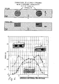
- the two-dimensional diagram a) shows, in a gray scale, the values of the inner product ( B ⁇ b ), related with the magnet-sensor geometry, in the region between the exciting magnet and one sensor: darker areas denote a positive inner product and a higher intensity, brighter areas denote a decreasing intensity until the inner product reaches negative values.
- this inner product is generally not uniform in space, and varies in terms of both intensity and sign.
- the magnetic field hence the sensitivity of the instrument, depends from the product ( B ⁇ b ).
- the region of space (hereafter sensitivity region), in which this product is substantially other than zero, has the shape of a cylinder which is coaxial with the field and in one specific embodiment, has a diameter of about 6 cm and a volume of 200 ml.
- the inner product ( B ⁇ b ) is shown as a function of the position x on the axis of symmetry of the magnetic field.
- the inner product ( B ⁇ b ) is shown as a function of the radial position y on an axis equidistant from the magnet and the sensor.
- Figure 4 shows the signal produced by they repeated insertion and extraction of a 170 cc water sample, contained in a plastic container, in and from the apparatus.
- the contribution of a water sample, integrally contained in this region, to the signal is of -30nV/g, whereas the contribution of a sample outside the region is substantially null.
- the water sample signal increases with the sample volume.
- the magnetic field in the sensitivity region is no higher than a few tens of Gauss and oscillates at a frequency of a few hundreds of Hz.
- the sensitivity of the apparatus allows to detect a susceptibility variation of 0.5%, which is equivalent to an iron concentration variation of 0.030 mg/g (see Fig. 4 ). Iron concentration measuring sensitivity worsens as the sample volume decreases.
- An instrumental noise of 25nV is about 3 parts per 10 8 of the signal at the ends of each sensor. It shall be noted that, in order to detect relative field variations below one part per 10 7 , relative variations in the susceptometer size, during the measuring step, shall be of the same order of magnitude or lower: the susceptometer of the invention allows to reach this result.
- the spatial inhomogeneity of the inner product ( B ⁇ b ) allows to obtain different signals depending on the location of a sample relative to the sensitivity region.
- the diagrams of these figures show the curve of the signal detected by the apparatus as a function of the sample position in the screening region with reference to a neutral axis (0 position), corresponding to the median axis of the region, relative to a sample with an inhomogeneous arrangement of iron ions.
- the sample is contained in a prismatic plastic case, having a volume of about 410 cc.
- curve a) is related to a demineralized water sample
- curves b), c) and d) are related to the signal generated by samples that contain, inside the main casing, a second case with 16 cc of an iron ion solution with a concentration of about 3000 ⁇ g Fe /cc; in the three curves b), c) and d), the secondary case is positioned in different regions of the main case, to create a sample with an inhomogeneous iron distribution.
- curve a) is related to a demineralized water sample
- curve b) is related to the signal generated by a sample that contains, inside the main casing, a second case with 16 cc of an iron ion solution with a concentration of about 3000 ⁇ g Fe /cc
- curve c) is related to the signal generated by a sample that contains, inside the main casing, two cylindrical cases, each containing about 16 cc of an iron ion solution with a concentration of about 3000 ⁇ g Fe /cc.
- Figs. 5 and 6 clearly show that this specific embodiment of the apparatus has a spatial resolution of about 2 cm, i.e. it may resolve iron accumulations at a distance of more than 2 cm from each other.
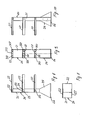
- Fig. 7 in the proximity of the field source 2 two additional sensors 20, 22 are mounted in symmetrical positions with respect to the source 2.
- the additional sensors 20, 22 are disposed in such a manner that the variation in the magnetic field fluxes linked therewith, caused by the presence of a body in the sensitivity region, is substantially a function of the magnetic properties of the outermost areas of this body only.
- the measuring configuration of Fig. 7 allows to determine the magnetic properties of the inner region of the sample, by subtracting, with an appropriate weight, the signal produced by the sensors 20, 22, from the signal produced by the sensors 4, 6.
- An advantageous embodiment of the susceptometer as shown in the preceding Figures 1 to 7 also has, alternatively to or in combination with the foamed tunnels 12 and 14, a gap for feeding a flow of diathermic liquid, particularly water, at a controlled temperature.
- the heat given to the apparatus by the screened body, which is accommodated in the foamed tubular chambers, was found to have a detectable effect, which causes a signal drift, due to infinitesimal variations of the structure supporting the magnetic field generator and the magnetic field sensors.
- the diathermic temperature-controlled liquid flow removes the heat generated and introduced in the susceptometer structure by the body being screened.
- An additional variant consists in removing both the foamed tubular members, and the casing 16 of the embodiment described with reference to Figure 1 .
- the susceptometer structure is housed in a case whose shape corresponds to the structure of the assembly composed of the supporting members, the magnetic field source and the magnetic field sensing pick-ups and the case has a two-shell conformation, in which a liquid-tight gap is formed, having at least one feed inlet and one drain outlet, to obtain a diathermic fluid flow, which surrounds at least the most relevant parts or substantially the whole structure of said assembly composed of the support structure, the magnetic field source, and the magnetic field sensing pick-ups.
- This construction configuration has the advantage of reducing the size of the device, thanks to the removal of the casing 16 as shown in Figure 1 and of avoiding the use of foamed tunnels 12 and 14, which is desirable in apparatuses designed for examinations on human beings.
- the temperature of the susceptometer may be stabilized thanks to a feedback control of the fluid around it.
- Magnet temperature is itself measured with a high sensitivity, and controlled by a feedback system, which modulates the temperature of water flowing through the hollow copper conductors that form magnets.
- the susceptometer has a support structure 20, including an upright 21 with three vertically aligned cantilevers 22 which project on the same side and support the two magnetic field sensing pick-ups and the magnetic field source respectively, in the above specified order, i.e. with the magnetic field source between the two magnetic field sensing pick-ups.
- the upright 20 has the shape of a hollow panel or rectangular beam as is apparent from the vertical cross section of Fig. 10 and from the top plan view of Fig. 11 .
- the cantilevers 22 are themselves provided as hollow panels adapted to receive the pickups and the magnetic field source respectively, not shown in detail in Figures 8 to 11 .
- the panels At the end attached to the upright 21, the panels have fastening tabs 122, which are provided as extensions of the vertical side walls, abutting against the corresponding opposite sides of the upright 21.
- the tabs are fastened with the help of dowels and fast pins, which are denoted as 23 and 24 respectively.
- a trapezoidal base member 25 for each side wall of the upright 21 acts as a reinforced fastener between said upright 21 and a base plate 26.
- holes 222 and 322 are formed at the end sides of the cantilevers 22, for the insertion of dowels, and fast pins respectively, to secure the magnetic field source and of the pick-ups in the corresponding cantilever.
- the structure 20 is made of a non-magnetic material, for instance plastic or fiber-reinforced resin, for instance glass reinforced plastics.
- the structure 20 has a vertical comb shape.
- said structure 21 with its pick-ups and the magnetic field source and possibly with sensors and leads for connection with other required construction members are housed in a first inner shell 30 having a corresponding shape and in another outer shell 31, also having a corresponding shape, but such a size as to form a gap for the flow of the above generally described diathermic liquid between the inner shell 30 and the outer shell 31, which are joined together at the rear side and at the base plate to form a gap which is liquid-tight towards the outside of the outer shell 31 and the inside of the inner shell 30.
- the gap communicates with a diathermic fluid feed and drain line through inlets and outlets not shown in detail.
- the two casings with different sizes have a portion 130, 131 which is adapted to receive the upright 21 and cavities 230, 231 for receiving the cantilevers 22.
- the cavities 230, 231 communicate with the cavities 130, 131 of the upright 21 of the support structure 20, whereas the latter increases in width as it gets closer to the bottom portion, as a trapezium, to form the housing cavity of the trapezoidal base o the support structure.
- this cavity of the trapezoidal base provides a better stability to the structure and other support members 32 may be associated thereto, such as side cross members which, if designed with a tubular shape, may also form inlets and outlets for the diathermic flow, besides improving themselves stability of the whole structure.
- the distance between the central magnetic field source and the two pick-ups disposed on opposite sides of the magnetic field source, i.e. between the corresponding cantilevers 22 is such as to allow the introduction of the patient body or a patient table or stretcher between said magnetic field source and one of the two opposite pick-ups.
- the stretcher is fitted on a frame that may be lifted and lowered to allow vertical motion of the supporting surface of the table or stretcher, until it reaches the height whereat the stretcher with the patient body on it may be introduced either in the space between the upper pick-up and the intermediate magnetic field source or in the space between said intermediate field and the lower pick-up.
- the stretcher may have a recess, whose size and shape substantially correspond to those of the cantilevers or an aperture coinciding with the body part to be screened, typically the liver.
- Figs. 13 to 15 show a patient table combined with the inventive susceptometer.
- the table 40 is shown in Figs. 13 and 14 in its two operating positions.
- the table structure is composed of a surface for supporting the body under examination, possibly having a recess whose shape is complementary to the cantilever shape, and in which either the cantilever with the lower pick-up ( Fig. 13 ) or the one with the magnetic field source ( Fig. 14 ) may penetrate, in the operating condition, to carry the body part to be screened in the proper position, in line with the pick-ups and with the magnetic field source.
- the patient does not need to be moved relative to the stretcher or table 40, and always keeps its position through the two or more different measuring steps, thereby simplifying data analysis.
- the same patient turns his/her back or abdomen to the magnetic field source depending on his/her insertion in the space above or below the magnetic field source.
- several measurements may be made, particularly at least two measurements, each with a different patient orientation with respect to the three magnetic field sources, hence the three magnetic fields generated thereby.Also, when two different magnetic field measuring pick-ups are used ( Fig. 16 ), 12 measurements may be made for each patient position relative to the magnetic field axis, and this allows for a simpler determination of excess iron stores in the body and of the distribution thereof.
- the table or stretcher is supported by a member composed of jointed arms, which allows the table or stretcher to be positioned at different heights.
- the lower ends of four lifting arms 42 are jointed to a base of the table 40 which acts as a trolley 41.
- An arm 42 is provided on each transverse side of the table, and is jointed at its ends to the base 41 and to the body supporting surface 40 respectively.
- the axes of articulation of the two arms 42 are coincident.
- a second arm 42' for each jointed arm 42 is in turn jointed to the base 41, but it is free to run to the upper end toward the plane defined by the arm 42' and passes through an aperture 142 of the arm 42.
- Abutment means are provided along the arm 42, which engage with the edges of the aperture 142 and allow the surface to be locked in position, preventing the table to be lowered unless it is previously released by a slight lifting action.
- the base 41 and the patient supporting surface 43 overhang from the structure side 20, that carries the magnetic field source 2 and the pick-ups 4, 6, the arm system 42, 42', being eccentric with respect to said two surfaces.
- all the structural support members of the apparatus and table, as well as the shells that form the susceptometer case are made of a non-magnetic material, particularly glass-reinforced plastics or the like.
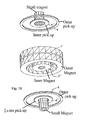
- FIG 16 A further embodiment of the magnetic field source and the pick-ups is shown in Figure 16 .
- two magnetic field sources 2 and 2' are provided, having different extensions, and hence being able to generate magnetic fluxes in a larger volume and in a smaller volume.
- two pick-ups 4, 4' and 6, 6' are provided on each side of the two magnetic field sources 2, 2', and in line therewith, to sense the magnetic fields generated by the larger source 2 and by the smaller source 2'.
- the two sources 2, 2' are made of two circular annular superconducting coils, with hollow copper conductors, which are coaxial and concentric.
- the pick-ups 4, 4' and 6, 6' of the two pairs of pick-ups are made of coaxial and concentric circular annular coils, whose positions are axially coincident with the corresponding magnetic field generating coil for said two sources 2, 2'.In order to minimize the stray capacity of pick-ups, the latter are formed of several superposed printed circuit layers.
- An additional magnet may be positioned coaxially inside the inner pickups 4' and 6'.
Landscapes
- Health & Medical Sciences (AREA)
- Life Sciences & Earth Sciences (AREA)
- Pathology (AREA)
- Chemical & Material Sciences (AREA)
- General Health & Medical Sciences (AREA)
- Physics & Mathematics (AREA)
- Engineering & Computer Science (AREA)
- Nuclear Medicine, Radiotherapy & Molecular Imaging (AREA)
- Biomedical Technology (AREA)
- Heart & Thoracic Surgery (AREA)
- Medical Informatics (AREA)
- Molecular Biology (AREA)
- Surgery (AREA)
- Animal Behavior & Ethology (AREA)
- Radiology & Medical Imaging (AREA)
- Public Health (AREA)
- Veterinary Medicine (AREA)
- Biophysics (AREA)
- Chemical Kinetics & Catalysis (AREA)
- Electrochemistry (AREA)
- Analytical Chemistry (AREA)
- Biochemistry (AREA)
- General Physics & Mathematics (AREA)
- Immunology (AREA)
- Investigating Or Analyzing Materials By The Use Of Magnetic Means (AREA)
- Investigating Or Analysing Materials By Optical Means (AREA)
- Investigating Or Analyzing Materials By The Use Of Ultrasonic Waves (AREA)
- Artificial Fish Reefs (AREA)
Claims (40)
- Suszeptibilitätsmeßgerät zur nichtinvasiven Messung des Eisengehaltes in einem Körper durch Nachweisen der Veränderung des magnetischen Flusses, welcher von dem Körper erzeugt wird, mit:- einem Wärmeisolierungsgehäuse (16) mit einer Trägerstruktur, welche aus einem nichtmagnetischen und elektrisch isolierenden Material gemacht ist und im Wesentlichen auf Raumtemperatur gehalten wird und welche einen Durchleuchtungsbereich (8, 10) definiert;- einer alternierenden Magnetfeldquelle (2) welche durch die Struktur gestützt wird und ein magnetisches Feld in dem Durchieuchtungsbereich erzeugt;- wenigstens zwei Magnetfeldsensoren (4, 6), welche durch die Struktur gestützt werden und hinsichtlich der Feldquelle (2) symmetrisch angeordnet sind;- Mittel (12, 14) zum Einführen des Körpers zum Durchleuchten in dem Durchleuchtungsbereich (8, 10), welcher durch die Feldquelle (2) und wenigstens einem der wenigstens zwei Sensoren (4, 6) definiert ist;- Temperaturkontrollmittel zum Stabilisieren der Temperatur in dem Gehäuse wenigstens während der Messung in der Weise, daß die relative Änderung auf einen vorbestimmten maximalen Wert begrenzt ist, so daß eine thermische Ausdehnung der Trägerstruktur und der damit verbundenen Feldquelle (2) und der Sensoren (4, 6) im Wesentlichen ohne Einfluß auf die Veränderungen in dem magnetischen Feldfluß in Verbindung mit den Sensoren (4, 6) ist; und- Mittel zur Verarbeitung von elektrischen Signalen, welche für die Änderung des magnetischen Flusses in Verbindung mit dem Sensor indikativ sind, wobei die Änderung durch die Anwesenheit des zu durchleuchtenden Körpers in dem Durchleuchtungsbereich bewirkt wird, gekennzeichnet durch ein zweites Wärmeisolierungsgehäuse (18), welches innerhalb des Gehäuses eine Umgebung mit einer kontrollierten Temperatur definiert.
- Meßgerät nach Anspruch 1,
dadurch gekennzeichnet,
daß es einen ersten (4) und einen zweiten (6) Sensor hat, welche an der Trägerstruktur in symmetrischen Positionen hinsichtlich der Feldquelle (2) angeordnet sind und worin ein Durchleuchtungsbereich (8, 10) zwischen der Feldquelle (2) und jedem Sensor (4, 6) definiert ist. - Meßgerät nach einem oder mehreren der vorhergehenden Ansprüche,
dadurch gekennzeichnet,
daß weiterhin wenigstens zwei zusätzliche Sensoren (20, 22) vorgesehen sind, welche durch die Struktur gestützt werden und in der Nähe der Feldquelle (2) und vor der Quelle angeordnet sind, so daß die Änderung des magnetischen Feldflusses in Verbindung mit den zusätzlichen Sensoren, welche durch die Anwesenheit eines Körpers in diesem Durchleuchtungsbereich bewirkt wird, im Wesentlichen der Effekt der magnetischen Eigenschaften der äußeren Teile des Körpers ist. - Meßgerät nach Anspruch 1,
dadurch gekennzeichnet,
daß die Mittel zum Einführen des Körpers zum Durchleuchten einen ersten (12) und einen zweiten (14) Tunnel aufweisen, welche aus einem nichtmagnetischen isolierenden Material sind und entsprechend in den Durchleuchtungsbereichen (8, 10) angeordnet sind, wobei eine Einführöffnung außerhalb der Wände des ersten (16) und des zweiten (18) Gehäuses vorgesehen sind. - Meßgerät nach einem oder mehreren der vorhergehenden Ansprüche,
dadurch gekennzeichnet,
daß die Temperaturkontrollmittel eine Vielzahl von Heizungs/Kühlungsmittel, welche mit der Trägerstruktur verbunden sind, Temperaturnachweismittel zum Nachweisen der Temperatur nahe der Heizungs/Kühlungsteile und Mittel zum Einstellen der Temperatur der Heizungs/Kühlungsmittel als eine Funktion der durch die Sensoren gemessene Temperatur enthalten. - Meßgerät nach Anspruch 5,
dadurch gekennzeichnet,
daß die Heizungs/Kühlungsmittel schwache magnetische Eigenschaften haben. - Meßgerät nach einem oder mehreren der vorhergehenden Ansprüche 1 bis 4,
dadurch gekennzeichnet,
daß die Temperaturkontrollmittel Heizungs/Kühlungsmittel aufweisen, welche mit den Wänden des ersten Gehäuses (16) und/oder des zweiten Gehäuses (18) verbunden sind. - Meßgerät nach Anspruch 4,
dadurch gekennzeichnet,
daß die Temperaturkontrollmittel Heizungs/Kühlungsmittel aufweisen, welche mit den Wänden des ersten (12) und zweiten (14) Tunnels verbunden sind. - Meßgerät nach einem oder mehreren der vorhergehenden Ansprüche 1 bis 8,
dadurch gekennzeichnet,
daß die Verarbeitungsmittel einen Lock-in-Verstärker aufweisen, welcher das von den Sensoren erzeugte Signal liest, wobei das von dem Lock-in-Verstärker gelesene Signal Null ist, wenn keine Probe in dem Durchleuchtungsbereich eingeschoben ist. - Meßgerät nach Anspruch 9,
dadurch gekennzeichnet,
daß die Verarbeitungsmittel einen Computer aufweisen, welcher das Ausgangssignal des Lock-in-Verstärkers synchron mit dem Einführen und Herausnehmen der Probe von dem Durchleuchtungsbereich erhält. - Meßgerät nach einem oder mehreren der vorhergehenden Ansprüche,
dadurch gekennzeichnet,
daß das erste Gehäuse (16, 18; 30, 31) und das zweite Gehäuse zwischen sich eine flüssigkeitsdichte Lücke definieren, durch welche eine temperaturkontrollierte diathermische Flüssigkeit fließt, um die Temperatur der Meßgerätsstruktur zu stabilisieren. - Meßgerät nach einem oder mehreren der vorhergehenden Ansprüche,
dadurch gekennzeichnet,
daß es eine Trägerstruktur für die magnetische Feldquelle/n (2, 2' und kleiner Magnet) und die Pick-up/s (4, 4'; 6, 6') mit einem Ständer (21) hat, wovon drei Ausleger (22) in verschiedenen Höhen und im Wesentlichen in ausgerichteten Positionen herausragen, um die magnetische Feldquelle/n (2, 2' und kleiner Magnet) und die Pick-up/s (4, 4'; 6, 6') zu unterstützen. - Meßgerät nach Anspruch 12,
dadurch gekennzeichnet,
daß der Ständer (21) und/oder die Ausleger (22) als röhrenförmige oder kastenähnliche Elemente, wie Platten, ausgebildet sind und lösbar miteinander durch Schließmittel und/oder Zentriermittel befestigt sind. - Meßgerät nach Anspruch 11 oder 12,
dadurch gekennzeichnet,
daß die Ausleger (22) mit dem Ständer durch Verlängerungen ihrer senkrechten Seitenwände verbunden sind, welche die Form von Befestigungsstreifen haben können, und welche gegen die entsprechenden Seitenwände des Ständers (21) anstoßen und daran mittels Befestigungsstiften und Dübeln (23, 24) gesichert sind. - Meßgerät nach einem oder mehreren der vorhergehenden Ansprüche 11 bis 14,
dadurch gekennzeichnet,
daß die Ausleger (22) Hohlräume zur Aufnahme der Pick-up/s (4, 4'; 6, 6') und der entsprechenden Magnetfeldquelle/n (2, 2' und kleiner Magnet) haben, wobei die Hohlräume innerhalb der Dicke der Ausleger ausgebildet sind. - Meßgerät nach einem oder mehreren der vorhergehenden Ansprüche 11 bis 15,
dadurch gekennzeichnet,
daß die Pick-up/s und die Magnetfeldquelle/n innerhalb der Dicke der Ausleger (22) durch Dübel (222) und Befestigungsstifte (322) gesichert sind. - Meßgerät nach einem oder mehreren der vorhergehenden Ansprüche 11 bis 16,
dadurch gekennzeichnet,
daß das untere Ende, auf welchem der Ständer ruht, mit einer Basisplatte mittels trapezförmiger Verstärkungsplatten (25) verbunden ist, welche mit der Basis (26) und den Seitenwänden des Ständers (21) befestigt sind. - Meßgerät nach einem oder mehreren der vorhergehenden Ansprüche 11 bis 17,
dadurch gekennzeichnet,
daß die Trägerstruktur (20) mit den Pick-up/s (4, 4'; 6, 6') und mit der Magnetfeldquelle/n (2, 2' und kleiner Magnet) in einer ersten Innenschale (30) untergebracht sind, welche einen Hohlraum (130) zur Aufnahme des Ständers (21) hat, wobei der Hohlraum mit drei Hohlräumen zur Aufnahme der Ausleger (22) in Verbindung steht und der untere Teil des ersten Hohlraums (130) verbreitert ist, um ein Trapez zu bilden, welches der Trapezbasis (25) der Trägerstruktur (20) entspricht. - Meßgerät nach Anspruch 18,
dadurch gekennzeichnet,
daß die Anordnung, welche aus der Trägerstruktur (20) mit den Pick-up/s (4, 4'; 6, 6') und mit der Magnetfeldquelle/n (2, 2' und kleiner Magnet) und ihrer ersten Innenschale (30) besteht, innerhalb einer zweiten Außenschale (31) aufgenommen ist, deren Form derjenigen der ersten Innenschale (30) entspricht und dessen Größe größer ist, um eine abdichtbare Lücke zu bilden, durch welche eine diathermische Flüssigkeit aus Gründen der Temperaturstabilisierung fließen kann. - Meßgerät nach einem oder mehreren der vorhergehenden Ansprüche 18 bis 19,
dadurch gekennzeichnet,
daß die erste Innenschale zwei röhrenförmige Tragbalken (32) entlang der Seitenwände an der trapezförmig aufgeweiteten Basis hat. - Meßgerät nach Anspruch 20,
dadurch gekennzeichnet,
daß die zwei röhrenförmigen Tragbalken (32) auch als Einlaß und Auslaß für die diathermische Flüssigkeit dienen, welche in der Lücke zwischen der Innenschale (30) und der Außenschale (31) fließt. - Meßgerät nach einem oder mehreren der vorhergehenden Ansprüche 11 bis 21,
dadurch gekennzeichnet,
daß es in Verbindung mit einem Patiententisch, einer Streckvorrichtung oder dergleichen (40) ausgebildet ist, wobei dessen Patientenunterstützungsoberfläche (34) in der Weise unterstützt ist, daß sie vertikal zwischen den zwei Betriebspositionen bewegt werden kann, in welche der zu durchleuchtende Körper eingeführt wird, und zwar zwischen dem Ausleger, welcher die Magnete (2, 2') trägt und dem Ausleger (22) für die unteren Pick-up/s (6, 6'). - Meßgerät nach Anspruch 22,
dadurch gekennzeichnet,
daß die Patientenunterstützungsoberfläche einen Hohlraum zur Aufnahme des Auslegers (22), welcher die unteren Pick-up/s (6, 6') trägt und/oder des Auslegers (22), welcher die magnetische Feldquelle/n (2, 2') trägt, hat. - Meßgerät nach den Ansprüchen 22 oder 23,
dadurch gekennzeichnet,
daß der Patiententisch oder die Streckvorrichtung (40) eine Basis (41) hat, welche auf Schienen läuft. - Meßgerät nach einem oder mehreren der Ansprüche 22 bis 24,
dadurch gekennzeichnet,
daß die Körperunterstützungsoberfläche (43) im Hinblick auf die Basis (41) mittels eines verbundenen Armhebesystems (42) und entfernbaren Positionshaltemitteln hochgehoben oder abgesenkt werden kann. - Meßgerät nach einem oder mehreren der vorhergehenden Ansprüche,
dadurch gekennzeichnet,
daß drei magnetische Feldquellen (2, 2' und kleiner Magnet) vorgesehen sind, wobei jede in der Lage ist, unterschiedliche magnetische Feldflußverteilungen zu erzeugen. - Meßgerät nach Anspruch 26,
dadurch gekennzeichnet,
daß die zwei Pick-up/s (4, 4'; 6, 6') an jeder Seite der magnetischen Feldquellen (2, 2') vorgesehen sind, wobei jede von der Dimension her an das Volumen angepaßt ist, welche von dem magnetischen Fluß der entsprechenden magnetischen Feldquelle (2, 2') durchdrungen wird. - Meßgerät nach einem oder mehreren der vorhergehenden Ansprüche,
dadurch gekennzeichnet,
daß zwei magnetische Feldquellen (2, 2') vorgesehen sind, welche durch ringförmige kreisförmige Spulen gebildet sind, welche unterschiedliche Durchmesser haben, wobei eine in der anderen angeordnet ist und beide koaxial zueinander und zu den zwei Pick-up/s (4, 4'; 6, 6') sind, wobei letztere selbst als Spulen ausgebildet sind, eine in der anderen und koaxial zueinander, wobei die Größe der konzentrischen Spulen (4, 4'; 6, 6') an die Größe der entsprechenden magnetischen Feldquelle (2, 2') angepaßt ist. - Meßgerät nach einem oder mehreren der vorhergehenden Ansprüche,
dadurch gekennzeichnet,
daß eine zusätzliche magnetische Feldquelle mit jedem Pick-up oder Pick-up-Paar (4, 4'; 6, 6') verbunden ist. - Meßgerät nach Anspruch 24,
dadurch gekennzeichnet,
daß die magnetische Feldquelle eine ringförmige Form hat und koaxial innerhalb des kleineren Pick-up von jedem Pick-up-Paar (4, 4'; 6, 6') montiert ist. - Verfahren zur Messung des Gehalts von magnetischem Material, insbesondere Metalle, insbesondere Eisen, in einem Körper durch eine suszeptometrische Messung von Feldänderungen, welche durch die Anwesenheit des zu durchleuchtenden Körpers in dem magnetischen Fluß bewirkt werden, mit einem Suszeptibilitätsmeßgerät gemäß einem oder mehreren der vorhergehenden Ansprüche 1 bis 30, wobei die folgenden Schritte vorgesehen sind:a) Erzeugen eines Meßmagnetfeldes,b) Messen des Magnetfeldes, welches den zu durchleuchtenden Körper durchdringt,c) Messen des Magnetfeldes ohne Körper zur Erzeugung eines Referenzsignals,d) Vergleichen des Referenzsignals mit dem Meßsignal, welches mit einem Körper in dem magnetischen Fluß erhalten wurde; das magnetische Material, welches in dem zu durchleuchtenden Körper enthalten ist, wird von der Differenz zwischen den beiden Signalen abgeleitet,dadurch gekennzeichnet,
daß das Referenzsignal und das aktuelle Körpersignal zur gleichen Zeit durch Erzeugen eines Magnetfeldes, welches symmetrisch im Hinblick auf eine magnetische Feldquelle ist, gemessen werden, wobei das Referenzsignal auf einer Seite der magnetischen Feldquelle gemessen wird und das aktuelle Körpersignal auf der gegenüberliegenden Seite der magnetischen Feldquelle gemessen wird, wobei der Aufbau von magnetischem Material in dem zu durchleuchtenden Körper von der Differenz zwischen den beiden Signalen abgeleitet wird. - Verfahren nach Anspruch 31,
dadurch gekennzeichnet,
daß die Messungen auch ausgeführt werden, indem die Position des zu durchleuchtenden Körpers im Hinblick auf die magnetische Feldquelle umgekehrt werden. - Verfahren nach Anspruch 31 oder 32,
dadurch gekennzeichnet,
daß die verschiedenen Messungen für jede Meßkonfiguration ausgeführt werden. - Verfahren nach einem oder mehreren der vorhergehenden Ansprüche 31 bis 33,
dadurch gekennzeichnet,
daß die Struktur zum Tragen der magnetischen Feldquelle und der Feldmeßmittel auf einer konstanten Temperatur während des Meßbetriebs gehalten wird. - Verfahren nach einem oder mehreren der vorhergehenden Ansprüche 31 bis 34,
dadurch gekennzeichnet,
daß die magnetischen Felder für jede Messung erzeugt werden, welche eine unterschiedliche räumliche Ausdehnung haben und breitere oder engere Teile des zu durchleuchtenden Körpers durchdringen. - Verfahren nach Anspruch 35,
dadurch gekennzeichnet,
daß die magnetischen Felder mit verschiedenen räumlichen Ausdehnungen koaxial zueinander sind. - Verfahren nach Anspruch 35 oder 36,
dadurch gekennzeichnet,
daß alle Messungen des Prozesses dazu verwendet werden, eine Eisenüberbelastung in dem menschlichen Körper und die Verteilung davon zu bestimmen. - Verfahren nach einem oder mehreren der vorhergehenden Ansprüche 31 bis 37 zur Bestimmung der Menge des Eisens, welches in der Leber gespeichert ist.
- Verfahren nach Anspruch 38 zur in vivo Bestimmung der Menge des Eisens, welches in der Leber gespeichert ist.
- Verfahren nach Anspruch 39 zur Bestimmung der Menge des Eisens, welches in der Leber von thalassämischen Patienten gespeichert ist.
Priority Applications (1)
| Application Number | Priority Date | Filing Date | Title |
|---|---|---|---|
| CY20091100708T CY1109188T1 (el) | 2002-12-13 | 2009-07-03 | Μετρητης επιδεκτικοτητας για μη επεμβατικη μετρηση του επιπεδου του σιδηρου σε ενα σωμα |
Applications Claiming Priority (1)
| Application Number | Priority Date | Filing Date | Title |
|---|---|---|---|
| PCT/EP2002/014251 WO2004055515A1 (en) | 2002-12-13 | 2002-12-13 | Susceptometer for non-invasive iron level measurement in a body |
Publications (2)
| Publication Number | Publication Date |
|---|---|
| EP1644730A1 EP1644730A1 (de) | 2006-04-12 |
| EP1644730B1 true EP1644730B1 (de) | 2009-04-08 |
Family
ID=32523968
Family Applications (1)
| Application Number | Title | Priority Date | Filing Date |
|---|---|---|---|
| EP02791823A Expired - Lifetime EP1644730B1 (de) | 2002-12-13 | 2002-12-13 | Suszeptibilitätmessgerät zur nichtinvasiven messung des eisengehalts in einem körper |
Country Status (8)
| Country | Link |
|---|---|
| US (1) | US7412275B2 (de) |
| EP (1) | EP1644730B1 (de) |
| AT (1) | ATE428112T1 (de) |
| AU (1) | AU2002358136A1 (de) |
| CY (1) | CY1109188T1 (de) |
| DE (1) | DE60231925D1 (de) |
| ES (1) | ES2322800T3 (de) |
| WO (1) | WO2004055515A1 (de) |
Families Citing this family (9)
| Publication number | Priority date | Publication date | Assignee | Title |
|---|---|---|---|---|
| US9427186B2 (en) * | 2009-12-04 | 2016-08-30 | Endomagnetics Ltd. | Magnetic probe apparatus |
| US10634741B2 (en) | 2009-12-04 | 2020-04-28 | Endomagnetics Ltd. | Magnetic probe apparatus |
| US20160270686A1 (en) * | 2012-08-24 | 2016-09-22 | The Trustees Of Dartmouth College | System and method for magnetic assessment of body iron stores |
| US9157975B2 (en) * | 2012-10-24 | 2015-10-13 | Siemens Medical Solutions Usa, Inc. | Concurrent fat and iron estimation in magnetic resonance signal data |
| CN105283202B (zh) | 2013-03-11 | 2019-04-23 | 安都磁学有限公司 | 用于淋巴结检测的低渗溶液 |
| US9234877B2 (en) | 2013-03-13 | 2016-01-12 | Endomagnetics Ltd. | Magnetic detector |
| US9239314B2 (en) | 2013-03-13 | 2016-01-19 | Endomagnetics Ltd. | Magnetic detector |
| ES2833377T3 (es) | 2015-06-04 | 2021-06-15 | Endomagnetics Ltd | Materiales marcadores y formas de localizar un marcador magnético |
| US10603501B2 (en) | 2016-06-15 | 2020-03-31 | Boston Scientific Neuromodulation Corporation | External charger for an implantable medical device having at least one sense coil concentric with a charging coil for determining position |
Citations (1)
| Publication number | Priority date | Publication date | Assignee | Title |
|---|---|---|---|---|
| US20020151779A1 (en) * | 1996-06-25 | 2002-10-17 | Avrin William F. | Susceptometers for foreign body detection |
Family Cites Families (2)
| Publication number | Priority date | Publication date | Assignee | Title |
|---|---|---|---|---|
| AU2869900A (en) * | 1997-02-27 | 2000-08-25 | Uri Rapoport | Method and apparatus for detecting a magnetically responsive substance |
| US6437563B1 (en) * | 1997-11-21 | 2002-08-20 | Quantum Design, Inc. | Method and apparatus for making measurements of accumulations of magnetically susceptible particles combined with analytes |
-
2002
- 2002-12-13 AT AT02791823T patent/ATE428112T1/de not_active IP Right Cessation
- 2002-12-13 DE DE60231925T patent/DE60231925D1/de not_active Expired - Lifetime
- 2002-12-13 ES ES02791823T patent/ES2322800T3/es not_active Expired - Lifetime
- 2002-12-13 WO PCT/EP2002/014251 patent/WO2004055515A1/en not_active Ceased
- 2002-12-13 AU AU2002358136A patent/AU2002358136A1/en not_active Abandoned
- 2002-12-13 EP EP02791823A patent/EP1644730B1/de not_active Expired - Lifetime
- 2002-12-13 US US10/538,411 patent/US7412275B2/en not_active Expired - Fee Related
-
2009
- 2009-07-03 CY CY20091100708T patent/CY1109188T1/el unknown
Patent Citations (1)
| Publication number | Priority date | Publication date | Assignee | Title |
|---|---|---|---|---|
| US20020151779A1 (en) * | 1996-06-25 | 2002-10-17 | Avrin William F. | Susceptometers for foreign body detection |
Also Published As
| Publication number | Publication date |
|---|---|
| AU2002358136A1 (en) | 2004-07-09 |
| US20070161887A1 (en) | 2007-07-12 |
| CY1109188T1 (el) | 2014-07-02 |
| ES2322800T3 (es) | 2009-06-29 |
| ATE428112T1 (de) | 2009-04-15 |
| US7412275B2 (en) | 2008-08-12 |
| EP1644730A1 (de) | 2006-04-12 |
| DE60231925D1 (de) | 2009-05-20 |
| WO2004055515A1 (en) | 2004-07-01 |
Similar Documents
| Publication | Publication Date | Title |
|---|---|---|
| US4827217A (en) | Low noise cryogenic apparatus for making magnetic measurements | |
| EP1372477B1 (de) | Vorrichtung für magnetische suszeptibilitätsmessungen am menschlichen körper und anderen proben | |
| US6208884B1 (en) | Noninvasive room temperature instrument to measure magnetic susceptibility variations in body tissue | |
| Ogawa et al. | Oxygenation‐sensitive contrast in magnetic resonance image of rodent brain at high magnetic fields | |
| Martin et al. | NMR Basic Principles and Progress | |
| Chu et al. | Bulk magnetic susceptibility shifts in NMR studies of compartmentalized samples: use of paramagnetic reagents | |
| US7759938B2 (en) | Apparatus and method for varying magnetic field strength in magnetic resonance measurements | |
| Bao et al. | Quantum‐based magnetic field sensors for biosensing | |
| Kuppusamy et al. | Three-dimensional spectral-spatial EPR imaging of free radicals in the heart: a technique for imaging tissue metabolism and oxygenation. | |
| Barfuss et al. | Whole-body MR imaging and spectroscopy with a 4-T system. | |
| US5050609A (en) | Magnetization transfer contrast and proton relaxation and use thereof in magnetic resonance imaging | |
| US4528510A (en) | Device for generating images of an object under examination using nuclear magnetic resonance | |
| Damadian | NMR in Medicine | |
| Damadian | Field focusing nmr (FONAR) and the formation of chemical images in man | |
| Farrell et al. | Magnetic measurement of human iron stores | |
| Wong et al. | A system for low field imaging of laser-polarized noble gas | |
| US7412275B2 (en) | Susceptometer for non-invasive iron level measurement in a body | |
| US7295006B2 (en) | Method for measuring nuclear magnetic resonance longitudinal axis relaxation time of blood and apparatus using the same | |
| Liebgott et al. | Proton electron double resonance imaging (PEDRI) of the isolated beating rat heart | |
| US4429277A (en) | Nuclear magnetic resonance apparatus utilizing multiple magnetic fields | |
| Mehta et al. | 6-Fluoropyridoxol: a novel probe of cellular pH using 19F NMR spectroscopy | |
| Carneiro et al. | Theoretical evaluation of the susceptometric measurement of iron in human liver by four different susceptometers | |
| GB2056088A (en) | Improvements in or relating to nuclear magnetic resonance systems | |
| EP0271913B1 (de) | Eichkörper für magnetische Kernresonanz-Diagnose | |
| Della Penna et al. | The use of an inhomogeneous applied field improves the spatial sensitivity profile of an in vivo SQUID susceptometer |
Legal Events
| Date | Code | Title | Description |
|---|---|---|---|
| PUAI | Public reference made under article 153(3) epc to a published international application that has entered the european phase |
Free format text: ORIGINAL CODE: 0009012 |
|
| 17P | Request for examination filed |
Effective date: 20050608 |
|
| AK | Designated contracting states |
Kind code of ref document: A1 Designated state(s): AT BE BG CH CY CZ DE DK EE ES FI FR GB GR IE IT LI LU MC NL PT SE SI SK TR |
|
| RAP1 | Party data changed (applicant data changed or rights of an application transferred) |
Owner name: MARINELLI, MAURO Owner name: E.O OSPEDALI GALLIERA |
|
| RIN1 | Information on inventor provided before grant (corrected) |
Inventor name: MARINELLI, MAURO |
|
| GRAP | Despatch of communication of intention to grant a patent |
Free format text: ORIGINAL CODE: EPIDOSNIGR1 |
|
| GRAS | Grant fee paid |
Free format text: ORIGINAL CODE: EPIDOSNIGR3 |
|
| GRAA | (expected) grant |
Free format text: ORIGINAL CODE: 0009210 |
|
| AK | Designated contracting states |
Kind code of ref document: B1 Designated state(s): AT BE BG CH CY CZ DE DK EE ES FI FR GB GR IE IT LI LU MC NL PT SE SI SK TR |
|
| REG | Reference to a national code |
Ref country code: GB Ref legal event code: FG4D |
|
| REG | Reference to a national code |
Ref country code: CH Ref legal event code: EP |
|
| REG | Reference to a national code |
Ref country code: CH Ref legal event code: NV Representative=s name: ABP PATENT NETWORK SWISS GMBH |
|
| REG | Reference to a national code |
Ref country code: IE Ref legal event code: FG4D |
|
| REF | Corresponds to: |
Ref document number: 60231925 Country of ref document: DE Date of ref document: 20090520 Kind code of ref document: P |
|
| REG | Reference to a national code |
Ref country code: ES Ref legal event code: FG2A Ref document number: 2322800 Country of ref document: ES Kind code of ref document: T3 |
|
| PG25 | Lapsed in a contracting state [announced via postgrant information from national office to epo] |
Ref country code: SI Free format text: LAPSE BECAUSE OF FAILURE TO SUBMIT A TRANSLATION OF THE DESCRIPTION OR TO PAY THE FEE WITHIN THE PRESCRIBED TIME-LIMIT Effective date: 20090408 |
|
| REG | Reference to a national code |
Ref country code: GR Ref legal event code: EP Ref document number: 20090401724 Country of ref document: GR |
|
| NLV1 | Nl: lapsed or annulled due to failure to fulfill the requirements of art. 29p and 29m of the patents act | ||
| PG25 | Lapsed in a contracting state [announced via postgrant information from national office to epo] |
Ref country code: PT Free format text: LAPSE BECAUSE OF FAILURE TO SUBMIT A TRANSLATION OF THE DESCRIPTION OR TO PAY THE FEE WITHIN THE PRESCRIBED TIME-LIMIT Effective date: 20090908 Ref country code: FI Free format text: LAPSE BECAUSE OF FAILURE TO SUBMIT A TRANSLATION OF THE DESCRIPTION OR TO PAY THE FEE WITHIN THE PRESCRIBED TIME-LIMIT Effective date: 20090408 Ref country code: AT Free format text: LAPSE BECAUSE OF FAILURE TO SUBMIT A TRANSLATION OF THE DESCRIPTION OR TO PAY THE FEE WITHIN THE PRESCRIBED TIME-LIMIT Effective date: 20090408 |
|
| PG25 | Lapsed in a contracting state [announced via postgrant information from national office to epo] |
Ref country code: NL Free format text: LAPSE BECAUSE OF FAILURE TO SUBMIT A TRANSLATION OF THE DESCRIPTION OR TO PAY THE FEE WITHIN THE PRESCRIBED TIME-LIMIT Effective date: 20090408 Ref country code: SE Free format text: LAPSE BECAUSE OF FAILURE TO SUBMIT A TRANSLATION OF THE DESCRIPTION OR TO PAY THE FEE WITHIN THE PRESCRIBED TIME-LIMIT Effective date: 20090708 |
|
| PG25 | Lapsed in a contracting state [announced via postgrant information from national office to epo] |
Ref country code: CZ Free format text: LAPSE BECAUSE OF FAILURE TO SUBMIT A TRANSLATION OF THE DESCRIPTION OR TO PAY THE FEE WITHIN THE PRESCRIBED TIME-LIMIT Effective date: 20090408 Ref country code: DK Free format text: LAPSE BECAUSE OF FAILURE TO SUBMIT A TRANSLATION OF THE DESCRIPTION OR TO PAY THE FEE WITHIN THE PRESCRIBED TIME-LIMIT Effective date: 20090408 Ref country code: EE Free format text: LAPSE BECAUSE OF FAILURE TO SUBMIT A TRANSLATION OF THE DESCRIPTION OR TO PAY THE FEE WITHIN THE PRESCRIBED TIME-LIMIT Effective date: 20090408 |
|
| PLBE | No opposition filed within time limit |
Free format text: ORIGINAL CODE: 0009261 |
|
| STAA | Information on the status of an ep patent application or granted ep patent |
Free format text: STATUS: NO OPPOSITION FILED WITHIN TIME LIMIT |
|
| PG25 | Lapsed in a contracting state [announced via postgrant information from national office to epo] |
Ref country code: SK Free format text: LAPSE BECAUSE OF FAILURE TO SUBMIT A TRANSLATION OF THE DESCRIPTION OR TO PAY THE FEE WITHIN THE PRESCRIBED TIME-LIMIT Effective date: 20090408 Ref country code: BE Free format text: LAPSE BECAUSE OF FAILURE TO SUBMIT A TRANSLATION OF THE DESCRIPTION OR TO PAY THE FEE WITHIN THE PRESCRIBED TIME-LIMIT Effective date: 20090408 |
|
| 26N | No opposition filed |
Effective date: 20100111 |
|
| PG25 | Lapsed in a contracting state [announced via postgrant information from national office to epo] |
Ref country code: BG Free format text: LAPSE BECAUSE OF FAILURE TO SUBMIT A TRANSLATION OF THE DESCRIPTION OR TO PAY THE FEE WITHIN THE PRESCRIBED TIME-LIMIT Effective date: 20090708 |
|
| PG25 | Lapsed in a contracting state [announced via postgrant information from national office to epo] |
Ref country code: MC Free format text: LAPSE BECAUSE OF NON-PAYMENT OF DUE FEES Effective date: 20100701 |
|
| REG | Reference to a national code |
Ref country code: IE Ref legal event code: MM4A |
|
| PG25 | Lapsed in a contracting state [announced via postgrant information from national office to epo] |
Ref country code: IE Free format text: LAPSE BECAUSE OF NON-PAYMENT OF DUE FEES Effective date: 20091213 |
|
| PG25 | Lapsed in a contracting state [announced via postgrant information from national office to epo] |
Ref country code: LU Free format text: LAPSE BECAUSE OF NON-PAYMENT OF DUE FEES Effective date: 20091213 |
|
| PG25 | Lapsed in a contracting state [announced via postgrant information from national office to epo] |
Ref country code: TR Free format text: LAPSE BECAUSE OF FAILURE TO SUBMIT A TRANSLATION OF THE DESCRIPTION OR TO PAY THE FEE WITHIN THE PRESCRIBED TIME-LIMIT Effective date: 20090408 |
|
| REG | Reference to a national code |
Ref country code: CH Ref legal event code: NV Representative=s name: ABP PATENT NETWORK AG, CH |
|
| REG | Reference to a national code |
Ref country code: FR Ref legal event code: PLFP Year of fee payment: 14 |
|
| REG | Reference to a national code |
Ref country code: DE Ref legal event code: R082 Ref document number: 60231925 Country of ref document: DE Representative=s name: MEPAT PATENTANWAELTE, DR. MEHL-MIKUS, GOY, DR., DE |
|
| REG | Reference to a national code |
Ref country code: CH Ref legal event code: PCAR Free format text: NEW ADDRESS: OTHMARSTRASSE 8, 8008 ZUERICH (CH) |
|
| REG | Reference to a national code |
Ref country code: FR Ref legal event code: PLFP Year of fee payment: 15 |
|
| REG | Reference to a national code |
Ref country code: FR Ref legal event code: PLFP Year of fee payment: 16 |
|
| REG | Reference to a national code |
Ref country code: FR Ref legal event code: PLFP Year of fee payment: 17 |
|
| PGFP | Annual fee paid to national office [announced via postgrant information from national office to epo] |
Ref country code: DE Payment date: 20181217 Year of fee payment: 17 Ref country code: GR Payment date: 20181206 Year of fee payment: 17 |
|
| PGFP | Annual fee paid to national office [announced via postgrant information from national office to epo] |
Ref country code: CH Payment date: 20181224 Year of fee payment: 17 Ref country code: GB Payment date: 20181213 Year of fee payment: 17 Ref country code: FR Payment date: 20181024 Year of fee payment: 17 Ref country code: IT Payment date: 20181213 Year of fee payment: 17 |
|
| PGFP | Annual fee paid to national office [announced via postgrant information from national office to epo] |
Ref country code: CY Payment date: 20181207 Year of fee payment: 17 Ref country code: ES Payment date: 20190129 Year of fee payment: 17 |
|
| REG | Reference to a national code |
Ref country code: DE Ref legal event code: R119 Ref document number: 60231925 Country of ref document: DE |
|
| PG25 | Lapsed in a contracting state [announced via postgrant information from national office to epo] |
Ref country code: CY Free format text: LAPSE BECAUSE OF NON-PAYMENT OF DUE FEES Effective date: 20191213 |
|
| REG | Reference to a national code |
Ref country code: CH Ref legal event code: PL |
|
| GBPC | Gb: european patent ceased through non-payment of renewal fee |
Effective date: 20191213 |
|
| PG25 | Lapsed in a contracting state [announced via postgrant information from national office to epo] |
Ref country code: DE Free format text: LAPSE BECAUSE OF NON-PAYMENT OF DUE FEES Effective date: 20200701 Ref country code: FR Free format text: LAPSE BECAUSE OF NON-PAYMENT OF DUE FEES Effective date: 20191231 Ref country code: IT Free format text: LAPSE BECAUSE OF NON-PAYMENT OF DUE FEES Effective date: 20191213 Ref country code: GR Free format text: LAPSE BECAUSE OF NON-PAYMENT OF DUE FEES Effective date: 20200707 Ref country code: GB Free format text: LAPSE BECAUSE OF NON-PAYMENT OF DUE FEES Effective date: 20191213 |
|
| PG25 | Lapsed in a contracting state [announced via postgrant information from national office to epo] |
Ref country code: CH Free format text: LAPSE BECAUSE OF NON-PAYMENT OF DUE FEES Effective date: 20191231 Ref country code: LI Free format text: LAPSE BECAUSE OF NON-PAYMENT OF DUE FEES Effective date: 20191231 |
|
| REG | Reference to a national code |
Ref country code: ES Ref legal event code: FD2A Effective date: 20210525 |
|
| PG25 | Lapsed in a contracting state [announced via postgrant information from national office to epo] |
Ref country code: ES Free format text: LAPSE BECAUSE OF NON-PAYMENT OF DUE FEES Effective date: 20191214 |