EP1644674B1 - Verfahren und vorrichtung zur kryogenen kühlung für hochtemperatursupraleitungsvorrichtungen - Google Patents
Verfahren und vorrichtung zur kryogenen kühlung für hochtemperatursupraleitungsvorrichtungen Download PDFInfo
- Publication number
- EP1644674B1 EP1644674B1 EP04776918.7A EP04776918A EP1644674B1 EP 1644674 B1 EP1644674 B1 EP 1644674B1 EP 04776918 A EP04776918 A EP 04776918A EP 1644674 B1 EP1644674 B1 EP 1644674B1
- Authority
- EP
- European Patent Office
- Prior art keywords
- cryogen
- cryogenic cooling
- recited
- liquid
- cooling system
- Prior art date
- Legal status (The legal status is an assumption and is not a legal conclusion. Google has not performed a legal analysis and makes no representation as to the accuracy of the status listed.)
- Expired - Lifetime
Links
- 238000001816 cooling Methods 0.000 title claims description 82
- 238000000034 method Methods 0.000 title claims description 28
- 239000002887 superconductor Substances 0.000 title claims description 8
- 239000007788 liquid Substances 0.000 claims description 114
- 238000009835 boiling Methods 0.000 claims description 28
- 238000012546 transfer Methods 0.000 claims description 27
- 238000009413 insulation Methods 0.000 claims description 15
- 238000013022 venting Methods 0.000 claims description 12
- 238000010438 heat treatment Methods 0.000 claims description 9
- 238000001704 evaporation Methods 0.000 claims description 6
- 230000008020 evaporation Effects 0.000 claims description 6
- RYGMFSIKBFXOCR-UHFFFAOYSA-N Copper Chemical compound [Cu] RYGMFSIKBFXOCR-UHFFFAOYSA-N 0.000 claims description 5
- 230000005855 radiation Effects 0.000 claims description 4
- 229910052802 copper Inorganic materials 0.000 claims description 3
- 239000010949 copper Substances 0.000 claims description 3
- 239000002184 metal Substances 0.000 claims description 2
- 229910052751 metal Inorganic materials 0.000 claims description 2
- 239000011555 saturated liquid Substances 0.000 claims 3
- 229910000881 Cu alloy Inorganic materials 0.000 claims 1
- 230000008878 coupling Effects 0.000 claims 1
- 238000010168 coupling process Methods 0.000 claims 1
- 238000005859 coupling reaction Methods 0.000 claims 1
- IJGRMHOSHXDMSA-UHFFFAOYSA-N Atomic nitrogen Chemical compound N#N IJGRMHOSHXDMSA-UHFFFAOYSA-N 0.000 description 91
- 229910052757 nitrogen Inorganic materials 0.000 description 48
- 239000007789 gas Substances 0.000 description 16
- 239000000463 material Substances 0.000 description 9
- 230000015556 catabolic process Effects 0.000 description 6
- 230000005494 condensation Effects 0.000 description 6
- 238000009833 condensation Methods 0.000 description 6
- QJGQUHMNIGDVPM-UHFFFAOYSA-N nitrogen group Chemical group [N] QJGQUHMNIGDVPM-UHFFFAOYSA-N 0.000 description 5
- 230000007704 transition Effects 0.000 description 5
- 239000007787 solid Substances 0.000 description 4
- 238000010586 diagram Methods 0.000 description 3
- 239000003989 dielectric material Substances 0.000 description 3
- 230000007246 mechanism Effects 0.000 description 3
- 230000008569 process Effects 0.000 description 3
- 230000007423 decrease Effects 0.000 description 2
- 238000010292 electrical insulation Methods 0.000 description 2
- 238000012986 modification Methods 0.000 description 2
- 230000004048 modification Effects 0.000 description 2
- 239000012071 phase Substances 0.000 description 2
- 239000000126 substance Substances 0.000 description 2
- 230000003466 anti-cipated effect Effects 0.000 description 1
- 230000004888 barrier function Effects 0.000 description 1
- 239000002826 coolant Substances 0.000 description 1
- 230000003247 decreasing effect Effects 0.000 description 1
- 238000006731 degradation reaction Methods 0.000 description 1
- 230000000593 degrading effect Effects 0.000 description 1
- 230000001419 dependent effect Effects 0.000 description 1
- 238000011161 development Methods 0.000 description 1
- 230000000694 effects Effects 0.000 description 1
- 239000007792 gaseous phase Substances 0.000 description 1
- 239000007791 liquid phase Substances 0.000 description 1
- 239000011159 matrix material Substances 0.000 description 1
- 238000012544 monitoring process Methods 0.000 description 1
- 230000000149 penetrating effect Effects 0.000 description 1
- 238000005086 pumping Methods 0.000 description 1
- 238000005057 refrigeration Methods 0.000 description 1
- 230000004044 response Effects 0.000 description 1
- 230000036962 time dependent Effects 0.000 description 1
Images


Classifications
-
- F—MECHANICAL ENGINEERING; LIGHTING; HEATING; WEAPONS; BLASTING
- F17—STORING OR DISTRIBUTING GASES OR LIQUIDS
- F17C—VESSELS FOR CONTAINING OR STORING COMPRESSED, LIQUEFIED OR SOLIDIFIED GASES; FIXED-CAPACITY GAS-HOLDERS; FILLING VESSELS WITH, OR DISCHARGING FROM VESSELS, COMPRESSED, LIQUEFIED, OR SOLIDIFIED GASES
- F17C1/00—Pressure vessels, e.g. gas cylinder, gas tank, replaceable cartridge
-
- F—MECHANICAL ENGINEERING; LIGHTING; HEATING; WEAPONS; BLASTING
- F25—REFRIGERATION OR COOLING; COMBINED HEATING AND REFRIGERATION SYSTEMS; HEAT PUMP SYSTEMS; MANUFACTURE OR STORAGE OF ICE; LIQUEFACTION SOLIDIFICATION OF GASES
- F25B—REFRIGERATION MACHINES, PLANTS OR SYSTEMS; COMBINED HEATING AND REFRIGERATION SYSTEMS; HEAT PUMP SYSTEMS
- F25B9/00—Compression machines, plants or systems, in which the refrigerant is air or other gas of low boiling point
-
- F—MECHANICAL ENGINEERING; LIGHTING; HEATING; WEAPONS; BLASTING
- F25—REFRIGERATION OR COOLING; COMBINED HEATING AND REFRIGERATION SYSTEMS; HEAT PUMP SYSTEMS; MANUFACTURE OR STORAGE OF ICE; LIQUEFACTION SOLIDIFICATION OF GASES
- F25B—REFRIGERATION MACHINES, PLANTS OR SYSTEMS; COMBINED HEATING AND REFRIGERATION SYSTEMS; HEAT PUMP SYSTEMS
- F25B49/00—Arrangement or mounting of control or safety devices
-
- F—MECHANICAL ENGINEERING; LIGHTING; HEATING; WEAPONS; BLASTING
- F25—REFRIGERATION OR COOLING; COMBINED HEATING AND REFRIGERATION SYSTEMS; HEAT PUMP SYSTEMS; MANUFACTURE OR STORAGE OF ICE; LIQUEFACTION SOLIDIFICATION OF GASES
- F25D—REFRIGERATORS; COLD ROOMS; ICE-BOXES; COOLING OR FREEZING APPARATUS NOT OTHERWISE PROVIDED FOR
- F25D19/00—Arrangement or mounting of refrigeration units with respect to devices or objects to be refrigerated, e.g. infrared detectors
- F25D19/006—Thermal coupling structure or interface
-
- F—MECHANICAL ENGINEERING; LIGHTING; HEATING; WEAPONS; BLASTING
- F17—STORING OR DISTRIBUTING GASES OR LIQUIDS
- F17C—VESSELS FOR CONTAINING OR STORING COMPRESSED, LIQUEFIED OR SOLIDIFIED GASES; FIXED-CAPACITY GAS-HOLDERS; FILLING VESSELS WITH, OR DISCHARGING FROM VESSELS, COMPRESSED, LIQUEFIED, OR SOLIDIFIED GASES
- F17C2201/00—Vessel construction, in particular geometry, arrangement or size
- F17C2201/01—Shape
- F17C2201/0104—Shape cylindrical
- F17C2201/0109—Shape cylindrical with exteriorly curved end-piece
-
- F—MECHANICAL ENGINEERING; LIGHTING; HEATING; WEAPONS; BLASTING
- F17—STORING OR DISTRIBUTING GASES OR LIQUIDS
- F17C—VESSELS FOR CONTAINING OR STORING COMPRESSED, LIQUEFIED OR SOLIDIFIED GASES; FIXED-CAPACITY GAS-HOLDERS; FILLING VESSELS WITH, OR DISCHARGING FROM VESSELS, COMPRESSED, LIQUEFIED, OR SOLIDIFIED GASES
- F17C2201/00—Vessel construction, in particular geometry, arrangement or size
- F17C2201/03—Orientation
- F17C2201/032—Orientation with substantially vertical main axis
-
- F—MECHANICAL ENGINEERING; LIGHTING; HEATING; WEAPONS; BLASTING
- F17—STORING OR DISTRIBUTING GASES OR LIQUIDS
- F17C—VESSELS FOR CONTAINING OR STORING COMPRESSED, LIQUEFIED OR SOLIDIFIED GASES; FIXED-CAPACITY GAS-HOLDERS; FILLING VESSELS WITH, OR DISCHARGING FROM VESSELS, COMPRESSED, LIQUEFIED, OR SOLIDIFIED GASES
- F17C2201/00—Vessel construction, in particular geometry, arrangement or size
- F17C2201/05—Size
- F17C2201/056—Small (<1 m3)
-
- F—MECHANICAL ENGINEERING; LIGHTING; HEATING; WEAPONS; BLASTING
- F17—STORING OR DISTRIBUTING GASES OR LIQUIDS
- F17C—VESSELS FOR CONTAINING OR STORING COMPRESSED, LIQUEFIED OR SOLIDIFIED GASES; FIXED-CAPACITY GAS-HOLDERS; FILLING VESSELS WITH, OR DISCHARGING FROM VESSELS, COMPRESSED, LIQUEFIED, OR SOLIDIFIED GASES
- F17C2203/00—Vessel construction, in particular walls or details thereof
- F17C2203/03—Thermal insulations
- F17C2203/0304—Thermal insulations by solid means
- F17C2203/0308—Radiation shield
-
- F—MECHANICAL ENGINEERING; LIGHTING; HEATING; WEAPONS; BLASTING
- F17—STORING OR DISTRIBUTING GASES OR LIQUIDS
- F17C—VESSELS FOR CONTAINING OR STORING COMPRESSED, LIQUEFIED OR SOLIDIFIED GASES; FIXED-CAPACITY GAS-HOLDERS; FILLING VESSELS WITH, OR DISCHARGING FROM VESSELS, COMPRESSED, LIQUEFIED, OR SOLIDIFIED GASES
- F17C2203/00—Vessel construction, in particular walls or details thereof
- F17C2203/03—Thermal insulations
- F17C2203/0391—Thermal insulations by vacuum
-
- F—MECHANICAL ENGINEERING; LIGHTING; HEATING; WEAPONS; BLASTING
- F17—STORING OR DISTRIBUTING GASES OR LIQUIDS
- F17C—VESSELS FOR CONTAINING OR STORING COMPRESSED, LIQUEFIED OR SOLIDIFIED GASES; FIXED-CAPACITY GAS-HOLDERS; FILLING VESSELS WITH, OR DISCHARGING FROM VESSELS, COMPRESSED, LIQUEFIED, OR SOLIDIFIED GASES
- F17C2203/00—Vessel construction, in particular walls or details thereof
- F17C2203/06—Materials for walls or layers thereof; Properties or structures of walls or their materials
- F17C2203/0602—Wall structures; Special features thereof
- F17C2203/0604—Liners
-
- F—MECHANICAL ENGINEERING; LIGHTING; HEATING; WEAPONS; BLASTING
- F17—STORING OR DISTRIBUTING GASES OR LIQUIDS
- F17C—VESSELS FOR CONTAINING OR STORING COMPRESSED, LIQUEFIED OR SOLIDIFIED GASES; FIXED-CAPACITY GAS-HOLDERS; FILLING VESSELS WITH, OR DISCHARGING FROM VESSELS, COMPRESSED, LIQUEFIED, OR SOLIDIFIED GASES
- F17C2203/00—Vessel construction, in particular walls or details thereof
- F17C2203/06—Materials for walls or layers thereof; Properties or structures of walls or their materials
- F17C2203/0602—Wall structures; Special features thereof
- F17C2203/0612—Wall structures
- F17C2203/0614—Single wall
- F17C2203/0617—Single wall with one layer
-
- F—MECHANICAL ENGINEERING; LIGHTING; HEATING; WEAPONS; BLASTING
- F17—STORING OR DISTRIBUTING GASES OR LIQUIDS
- F17C—VESSELS FOR CONTAINING OR STORING COMPRESSED, LIQUEFIED OR SOLIDIFIED GASES; FIXED-CAPACITY GAS-HOLDERS; FILLING VESSELS WITH, OR DISCHARGING FROM VESSELS, COMPRESSED, LIQUEFIED, OR SOLIDIFIED GASES
- F17C2205/00—Vessel construction, in particular mounting arrangements, attachments or identifications means
- F17C2205/01—Mounting arrangements
- F17C2205/0103—Exterior arrangements
- F17C2205/0111—Boxes
-
- F—MECHANICAL ENGINEERING; LIGHTING; HEATING; WEAPONS; BLASTING
- F17—STORING OR DISTRIBUTING GASES OR LIQUIDS
- F17C—VESSELS FOR CONTAINING OR STORING COMPRESSED, LIQUEFIED OR SOLIDIFIED GASES; FIXED-CAPACITY GAS-HOLDERS; FILLING VESSELS WITH, OR DISCHARGING FROM VESSELS, COMPRESSED, LIQUEFIED, OR SOLIDIFIED GASES
- F17C2205/00—Vessel construction, in particular mounting arrangements, attachments or identifications means
- F17C2205/01—Mounting arrangements
- F17C2205/0123—Mounting arrangements characterised by number of vessels
- F17C2205/0126—One vessel
-
- F—MECHANICAL ENGINEERING; LIGHTING; HEATING; WEAPONS; BLASTING
- F17—STORING OR DISTRIBUTING GASES OR LIQUIDS
- F17C—VESSELS FOR CONTAINING OR STORING COMPRESSED, LIQUEFIED OR SOLIDIFIED GASES; FIXED-CAPACITY GAS-HOLDERS; FILLING VESSELS WITH, OR DISCHARGING FROM VESSELS, COMPRESSED, LIQUEFIED, OR SOLIDIFIED GASES
- F17C2205/00—Vessel construction, in particular mounting arrangements, attachments or identifications means
- F17C2205/01—Mounting arrangements
- F17C2205/0153—Details of mounting arrangements
- F17C2205/018—Supporting feet
-
- F—MECHANICAL ENGINEERING; LIGHTING; HEATING; WEAPONS; BLASTING
- F17—STORING OR DISTRIBUTING GASES OR LIQUIDS
- F17C—VESSELS FOR CONTAINING OR STORING COMPRESSED, LIQUEFIED OR SOLIDIFIED GASES; FIXED-CAPACITY GAS-HOLDERS; FILLING VESSELS WITH, OR DISCHARGING FROM VESSELS, COMPRESSED, LIQUEFIED, OR SOLIDIFIED GASES
- F17C2205/00—Vessel construction, in particular mounting arrangements, attachments or identifications means
- F17C2205/03—Fluid connections, filters, valves, closure means or other attachments
- F17C2205/0302—Fittings, valves, filters, or components in connection with the gas storage device
- F17C2205/0338—Pressure regulators
-
- F—MECHANICAL ENGINEERING; LIGHTING; HEATING; WEAPONS; BLASTING
- F17—STORING OR DISTRIBUTING GASES OR LIQUIDS
- F17C—VESSELS FOR CONTAINING OR STORING COMPRESSED, LIQUEFIED OR SOLIDIFIED GASES; FIXED-CAPACITY GAS-HOLDERS; FILLING VESSELS WITH, OR DISCHARGING FROM VESSELS, COMPRESSED, LIQUEFIED, OR SOLIDIFIED GASES
- F17C2221/00—Handled fluid, in particular type of fluid
- F17C2221/01—Pure fluids
- F17C2221/014—Nitrogen
-
- F—MECHANICAL ENGINEERING; LIGHTING; HEATING; WEAPONS; BLASTING
- F17—STORING OR DISTRIBUTING GASES OR LIQUIDS
- F17C—VESSELS FOR CONTAINING OR STORING COMPRESSED, LIQUEFIED OR SOLIDIFIED GASES; FIXED-CAPACITY GAS-HOLDERS; FILLING VESSELS WITH, OR DISCHARGING FROM VESSELS, COMPRESSED, LIQUEFIED, OR SOLIDIFIED GASES
- F17C2223/00—Handled fluid before transfer, i.e. state of fluid when stored in the vessel or before transfer from the vessel
- F17C2223/01—Handled fluid before transfer, i.e. state of fluid when stored in the vessel or before transfer from the vessel characterised by the phase
- F17C2223/0146—Two-phase
- F17C2223/0153—Liquefied gas, e.g. LPG, GPL
- F17C2223/0161—Liquefied gas, e.g. LPG, GPL cryogenic, e.g. LNG, GNL, PLNG
-
- F—MECHANICAL ENGINEERING; LIGHTING; HEATING; WEAPONS; BLASTING
- F17—STORING OR DISTRIBUTING GASES OR LIQUIDS
- F17C—VESSELS FOR CONTAINING OR STORING COMPRESSED, LIQUEFIED OR SOLIDIFIED GASES; FIXED-CAPACITY GAS-HOLDERS; FILLING VESSELS WITH, OR DISCHARGING FROM VESSELS, COMPRESSED, LIQUEFIED, OR SOLIDIFIED GASES
- F17C2223/00—Handled fluid before transfer, i.e. state of fluid when stored in the vessel or before transfer from the vessel
- F17C2223/03—Handled fluid before transfer, i.e. state of fluid when stored in the vessel or before transfer from the vessel characterised by the pressure level
- F17C2223/033—Small pressure, e.g. for liquefied gas
-
- F—MECHANICAL ENGINEERING; LIGHTING; HEATING; WEAPONS; BLASTING
- F17—STORING OR DISTRIBUTING GASES OR LIQUIDS
- F17C—VESSELS FOR CONTAINING OR STORING COMPRESSED, LIQUEFIED OR SOLIDIFIED GASES; FIXED-CAPACITY GAS-HOLDERS; FILLING VESSELS WITH, OR DISCHARGING FROM VESSELS, COMPRESSED, LIQUEFIED, OR SOLIDIFIED GASES
- F17C2227/00—Transfer of fluids, i.e. method or means for transferring the fluid; Heat exchange with the fluid
- F17C2227/03—Heat exchange with the fluid
- F17C2227/0302—Heat exchange with the fluid by heating
- F17C2227/0304—Heat exchange with the fluid by heating using an electric heater
-
- F—MECHANICAL ENGINEERING; LIGHTING; HEATING; WEAPONS; BLASTING
- F17—STORING OR DISTRIBUTING GASES OR LIQUIDS
- F17C—VESSELS FOR CONTAINING OR STORING COMPRESSED, LIQUEFIED OR SOLIDIFIED GASES; FIXED-CAPACITY GAS-HOLDERS; FILLING VESSELS WITH, OR DISCHARGING FROM VESSELS, COMPRESSED, LIQUEFIED, OR SOLIDIFIED GASES
- F17C2227/00—Transfer of fluids, i.e. method or means for transferring the fluid; Heat exchange with the fluid
- F17C2227/03—Heat exchange with the fluid
- F17C2227/0337—Heat exchange with the fluid by cooling
- F17C2227/0341—Heat exchange with the fluid by cooling using another fluid
- F17C2227/0353—Heat exchange with the fluid by cooling using another fluid using cryocooler
-
- F—MECHANICAL ENGINEERING; LIGHTING; HEATING; WEAPONS; BLASTING
- F17—STORING OR DISTRIBUTING GASES OR LIQUIDS
- F17C—VESSELS FOR CONTAINING OR STORING COMPRESSED, LIQUEFIED OR SOLIDIFIED GASES; FIXED-CAPACITY GAS-HOLDERS; FILLING VESSELS WITH, OR DISCHARGING FROM VESSELS, COMPRESSED, LIQUEFIED, OR SOLIDIFIED GASES
- F17C2227/00—Transfer of fluids, i.e. method or means for transferring the fluid; Heat exchange with the fluid
- F17C2227/03—Heat exchange with the fluid
- F17C2227/0337—Heat exchange with the fluid by cooling
- F17C2227/0341—Heat exchange with the fluid by cooling using another fluid
- F17C2227/0355—Heat exchange with the fluid by cooling using another fluid in a closed loop
-
- F—MECHANICAL ENGINEERING; LIGHTING; HEATING; WEAPONS; BLASTING
- F17—STORING OR DISTRIBUTING GASES OR LIQUIDS
- F17C—VESSELS FOR CONTAINING OR STORING COMPRESSED, LIQUEFIED OR SOLIDIFIED GASES; FIXED-CAPACITY GAS-HOLDERS; FILLING VESSELS WITH, OR DISCHARGING FROM VESSELS, COMPRESSED, LIQUEFIED, OR SOLIDIFIED GASES
- F17C2227/00—Transfer of fluids, i.e. method or means for transferring the fluid; Heat exchange with the fluid
- F17C2227/03—Heat exchange with the fluid
- F17C2227/0367—Localisation of heat exchange
- F17C2227/0369—Localisation of heat exchange in or on a vessel
- F17C2227/0376—Localisation of heat exchange in or on a vessel in wall contact
- F17C2227/0379—Localisation of heat exchange in or on a vessel in wall contact inside the vessel
-
- F—MECHANICAL ENGINEERING; LIGHTING; HEATING; WEAPONS; BLASTING
- F17—STORING OR DISTRIBUTING GASES OR LIQUIDS
- F17C—VESSELS FOR CONTAINING OR STORING COMPRESSED, LIQUEFIED OR SOLIDIFIED GASES; FIXED-CAPACITY GAS-HOLDERS; FILLING VESSELS WITH, OR DISCHARGING FROM VESSELS, COMPRESSED, LIQUEFIED, OR SOLIDIFIED GASES
- F17C2250/00—Accessories; Control means; Indicating, measuring or monitoring of parameters
- F17C2250/06—Controlling or regulating of parameters as output values
- F17C2250/0605—Parameters
- F17C2250/061—Level of content in the vessel
-
- F—MECHANICAL ENGINEERING; LIGHTING; HEATING; WEAPONS; BLASTING
- F17—STORING OR DISTRIBUTING GASES OR LIQUIDS
- F17C—VESSELS FOR CONTAINING OR STORING COMPRESSED, LIQUEFIED OR SOLIDIFIED GASES; FIXED-CAPACITY GAS-HOLDERS; FILLING VESSELS WITH, OR DISCHARGING FROM VESSELS, COMPRESSED, LIQUEFIED, OR SOLIDIFIED GASES
- F17C2250/00—Accessories; Control means; Indicating, measuring or monitoring of parameters
- F17C2250/06—Controlling or regulating of parameters as output values
- F17C2250/0605—Parameters
- F17C2250/0626—Pressure
-
- F—MECHANICAL ENGINEERING; LIGHTING; HEATING; WEAPONS; BLASTING
- F17—STORING OR DISTRIBUTING GASES OR LIQUIDS
- F17C—VESSELS FOR CONTAINING OR STORING COMPRESSED, LIQUEFIED OR SOLIDIFIED GASES; FIXED-CAPACITY GAS-HOLDERS; FILLING VESSELS WITH, OR DISCHARGING FROM VESSELS, COMPRESSED, LIQUEFIED, OR SOLIDIFIED GASES
- F17C2250/00—Accessories; Control means; Indicating, measuring or monitoring of parameters
- F17C2250/06—Controlling or regulating of parameters as output values
- F17C2250/0605—Parameters
- F17C2250/0631—Temperature
-
- F—MECHANICAL ENGINEERING; LIGHTING; HEATING; WEAPONS; BLASTING
- F17—STORING OR DISTRIBUTING GASES OR LIQUIDS
- F17C—VESSELS FOR CONTAINING OR STORING COMPRESSED, LIQUEFIED OR SOLIDIFIED GASES; FIXED-CAPACITY GAS-HOLDERS; FILLING VESSELS WITH, OR DISCHARGING FROM VESSELS, COMPRESSED, LIQUEFIED, OR SOLIDIFIED GASES
- F17C2260/00—Purposes of gas storage and gas handling
- F17C2260/02—Improving properties related to fluid or fluid transfer
-
- F—MECHANICAL ENGINEERING; LIGHTING; HEATING; WEAPONS; BLASTING
- F17—STORING OR DISTRIBUTING GASES OR LIQUIDS
- F17C—VESSELS FOR CONTAINING OR STORING COMPRESSED, LIQUEFIED OR SOLIDIFIED GASES; FIXED-CAPACITY GAS-HOLDERS; FILLING VESSELS WITH, OR DISCHARGING FROM VESSELS, COMPRESSED, LIQUEFIED, OR SOLIDIFIED GASES
- F17C2260/00—Purposes of gas storage and gas handling
- F17C2260/02—Improving properties related to fluid or fluid transfer
- F17C2260/026—Improving properties related to fluid or fluid transfer by calculation
-
- F—MECHANICAL ENGINEERING; LIGHTING; HEATING; WEAPONS; BLASTING
- F17—STORING OR DISTRIBUTING GASES OR LIQUIDS
- F17C—VESSELS FOR CONTAINING OR STORING COMPRESSED, LIQUEFIED OR SOLIDIFIED GASES; FIXED-CAPACITY GAS-HOLDERS; FILLING VESSELS WITH, OR DISCHARGING FROM VESSELS, COMPRESSED, LIQUEFIED, OR SOLIDIFIED GASES
- F17C2260/00—Purposes of gas storage and gas handling
- F17C2260/03—Dealing with losses
- F17C2260/031—Dealing with losses due to heat transfer
- F17C2260/033—Dealing with losses due to heat transfer by enhancing insulation
-
- F—MECHANICAL ENGINEERING; LIGHTING; HEATING; WEAPONS; BLASTING
- F17—STORING OR DISTRIBUTING GASES OR LIQUIDS
- F17C—VESSELS FOR CONTAINING OR STORING COMPRESSED, LIQUEFIED OR SOLIDIFIED GASES; FIXED-CAPACITY GAS-HOLDERS; FILLING VESSELS WITH, OR DISCHARGING FROM VESSELS, COMPRESSED, LIQUEFIED, OR SOLIDIFIED GASES
- F17C2270/00—Applications
- F17C2270/05—Applications for industrial use
- F17C2270/0527—Superconductors
-
- H—ELECTRICITY
- H01—ELECTRIC ELEMENTS
- H01F—MAGNETS; INDUCTANCES; TRANSFORMERS; SELECTION OF MATERIALS FOR THEIR MAGNETIC PROPERTIES
- H01F6/00—Superconducting magnets; Superconducting coils
- H01F6/04—Cooling
Definitions
- the invention relates generally to a cryogenic cooling system for high temperature superconductor (HTS) devices and more particularly to a cryogenic cooling system for HTS devices having high-voltage electric power applications.
- HTS high temperature superconductor
- Fig. 1 is a p(pressure)-T(temperature) diagram showing the relationship amongst the p, T and the three phases (solid, liquid and vapor/gas) of a typical substance.
- the "Triple Point” is about 63.15K at 12.53kPa.
- liquid cryogen based cooling systems for high-voltage HTS devices rely in large degree on the dielectric properties of the liquid cryogen as the main electrical insulation medium.
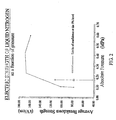
- Fig. 2 shows the dielectric strength of liquid nitrogen as a function of pressure.
- the other major factor is the bubbles that occur in the liquid nitrogen. Bubbles, especially large size bubbles, tend to reduce the dielectric strength of liquid nitrogen. Bubbles will be generated when objects submerged in liquid nitrogen are heated to above the boiling temperature of liquid nitrogen. Lowered boiling point in liquid nitrogen will thus make bubble generation more easily. Therefore method of lowering liquid nitrogen temperature by lowering its pressure will have negative impact on both factors that govern the dielectric strength of liquid nitrogen. Cooling systems based on such and similar approached are therefore ill suited for high-voltage HTS applications.
- a method according to claim 1 for designing a liquid-cryogen-based cryogenic cooling system for HTS devices that have the characteristics of lower operating temperature of liquid cryogen to improve the critical current density of HTS materials while at the same time substantially increasing the dielectric strength of the liquid cryogen, making such a cryogenic cooling system suitable for high-voltage applications.
- Such a method comprises the steps of maintaining a pressurized cryogen within the cryogen containment vessel that contains both liquid and gaseous regions of the cryogen. It further includes steps of maintaing the temperature of a portion or all of the liquid cryogen at and below its boiling temperature and within its sub-cooled temperature range using cryocooling means.
- a cyrogenic cooling system having an inner vessel, at least one HTS element, and an outer vessel.
- the space between the outer and inner vessel is maintained under a vacuum and multi-layer insulation (MLI) material is used to surround the inner vessel to provide it with thermal insulation to the radiation heat load.
- MMI multi-layer insulation
- the inner vessel is housed inside the outer vessel and stores liquid cryogen. Above the liquid cryogen region there is a gaseous region of the cryogen and is pressurized above one absolute atomospheric pressure. Liquid heating and gas venting means are in place to control and maintain the pressure within the inner vessel.
- a bucket or similar configuration made of dielectric materials is employed surrounding the HTS and throughout cryostat to ensure adequate high-voltage insulation.
- screens with small mesh sizes are deployed througout liquid cryogen regions to breakdown large-size bubbles generated during device operation.
- Another feature of this cryogenic cooling system is a thermal transfer plate that is disposed inside the inner vessel around the circumference to divide the liquid cryogen into two regions. The region below the plate is sub-cooled to a temperature that improves the performance of HTS. The region above the plate is a buffer region where a temperature transition occurs between the boundary of the liquid and gas regions and the boundary of the buffer region and the sub-cooled liquid region.
- the thermal transfer plate also couples the heat from both the temperature transition buffer region and the sub-cooled region to a cooling means such as a cryogenic refrigerator (cryocooler).
- a cryogenic refrigerator cryocooler
- the cryocooler is employed to maintain the temperature of the region below the plate to within the range of the sub-cooled liquid temperature range, from the boiling temperature at the pressure, to the triple point temperature of the liquid cryogen.
- the present invention generally relates to a cryogenic cooling systems for HTS device that have high-voltage applications even though it can also be applied to HTS devices that have other general purposes.
- the method of providing such a cryogenic cooling system includes maintaining a pressurized cryogen region that comprises a liquid as well as gaseous region, to above one absolute atmospheric pressure.
- the method further involves maintaining temperature of part or all of the liquid cryogen regions to below its boiling temperature (sub-cooled) using cooling means such as a cryogenic refrigerator (cryocooler).
- a method for designing a liquid-cryogen-based cryogenic cooling system for HTS devices that have the characteristics of lower operating temperature of liquid cryogen to improve the critical current density of HTS materials while at the same time substantially increasing the dielectric strength of the liquid cryogen, making such a cryogenic cooling system suitable for high-voltage applications.
- Such a method comprises the steps of maintaining a pressurized cryogen within the cryogen containment vessel that contains both liquid and gaseous regions of the cryogen. It further includes steps of maintaining the temperature of a portion or all of the liquid cryogen at and below its boiling temperature and within its sub-cooled temperature range using cryocooling means.
- a cyrogenic cooling system having an inner vessel, at least one HTS element, and an outer vessel.
- the space between the outer and inner vessel is maintained under a vacuum and multi-layer insulation (MLI), the material is used to surround the inner vessel to provide it with thermal insulation to the radiation heat load.
- MMI multi-layer insulation
- the inner vessel is housed inside the outer vessel and stores liquid cryogen. Above the liquid cryogen region there is a gaseous region of the cryogen and is pressurized above one absolute atmospheric pressure. Liquid heating and gas venting means are in place to control and maintain the pressure within the inner vessel. Heating boils liquid cryogen and evaporates to gaseous space thus increasing the pressure.
- Venting releases gaseous cryogen to the outside atmosphere thus reducing the pressure within the vessel.
- Such heating and venting process can be controlled by an automated monitoring and feedback system.
- bubbles especially large size bubbles, tend to degrade the dielectric strength of liquid cryogen. Bubbles can be generated when objects submerged in liquid cryogen get heated to above its boiling temperature. Pressurization raises the boiling temperature of the liquid cryogen. Raised boiling point will make bubble generation more difficult thus improving the dielectric properties of the liquid cryogen.
- a bucket or similar configuration made of dielectric materials can be employed surrounding the HTS and throughout cryostat to ensure adequate high-voltage insulation.
- thermo transfer plate that is disposed inside the inner vessel around the circumference to divide the liquid cryogen into two regions.
- the region below the plate is sub-cooled to a temperature that improves the performance of HTS.
- the region above the plate is a buffer region where a temperature transition occurs between the boundary of the liquid and gas regions and the boundary of the buffer region and the sub-cooled liquid region.
- the thermal transfer plate also couples the heat from both the temperature transition buffer region and the sub-cooled region to a cooling means such as a cryogenic refrigerator (cryocooler).
- the cryocooler is employed to maintain the temperature of the region below the plate to within the range of the sub-cooled liquid temperature range, from the boiling temperature at the pressure, to the triple point temperature of the liquid cryogen. If the liquid cryogen is sub-cooled to below its triple point temperature, solid cryogen will begin to form which may or may not be a desired result. In the case when sub-cooling is achieved through the use of a cryocooler, such a practice is not desired since at or below the triple point temperature, solid cryogen will form around the interface to the cryocooler and significantly degrade the cooling performance of the cryocooler.
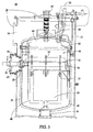
- a cryogenic cooling system 10 of the present invention comprises an outer containment vessel 12, an inner containment vessel 18 adapted to be contained inside the outer vessel 12, a venting port 30 pneumatically coupled to the inner vessel, a high-voltage bushing 14 electrically and mechanically coupled to the inner vessel 18, and a cryocooler 20 that is thermally and mechanically coupled to the inner vessel.
- the high-voltage bushing 14 can be used to supply electric current to HTS 24 and is connected to the outside high-voltage power sources such as an electric power grid.
- HTS 24 is coupled to a HTS support 32, which in turn is coupled to a thermal transfer medium 26.
- a copper ring 36 is mounted along the circumference of the inner vessel and is securely affixed to a thermal transfer medium 26.
- An inner vessel support 34 is coupled to the inner vessel 18.
- HTS 24 may also be the HTS assembly of a matrix fault current limiter (MFCL) as described by US patent application 2003/0021074A1 , assigned to the assignee of the present invention and herein incorporated by reference
- MFCL matrix fault current limiter
- MMI multi-layer insulation
- An inner vessel venting port 30 provides gas-venting means for inner vessel 18 to reduce the gas pressure in inner vessel 18. Additionally, an auxiliary gas evaporation heater 52 may be employed to heat and boil liquid cryogen to increase the pressure of the inner vessel 18.
- the size of the inner vessel 18 can be determined to provide adequate cooling capacity to meet cooling requirements for the HTS 24.
- the inner vessel 18 houses cryogen that has a liquid as well as a gaseous region.
- the cryogen is nitrogen and is pressurized at 0.3MPa in order to achieve the optimum dielectric strength of liquid nitrogen per Fig. 2 .
- Bubbles, especially large-size bubbles in the liquid nitrogen could degrade its dielectric strength.
- Bubble generates when heat generated in HTS 24 causes its temperature to be above the boiling temperature of the liquid nitrogen it submerges in.
- Increasing the pressure in a cryostat also increases the boiling temperature of the liquid nitrogen.
- the nitrogen pressure is maintained at 0.3MPa, the boiling temperature of liquid nitrogen is elevated to 88K compared to the 77K at 0.1MPa. This makes the bubble generation more difficult therefore improves the electrical insulation properties of the liquid cryogen.
- HTS 24 is surrounded by a dielectric medium 38 that acts an electric insulation barrier.
- Other measures of improving the high-voltage insulation of the cryogenic cooling system include, placing buckets, tubes, boxes or screens or similar objects made from dielectric materials in a meshed configuration to breakdown the size of bubbles if they were generated during the device operation.
- the cell dimensions of the mesh structure or apertures are selected to be sufficiently small so that any bubbles penetrating the screen will become small enough so that they will not cause substantial degradation of dielectric strength of liquid nitrogen and will not cause any voltage insulation breakdown within HTS 24 and its surrounding environment.
- the screen apertures have a diameter in a range up to 5 millimeters.
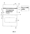
- the surface temperature at the liquid and gaseous nitrogen boundary 42 is the boiling (saturation) temperature of the boiling liquid nitrogen which is 88K.
- the liquid nitrogen region is further divided into two regions by a thermal transfer medium 26.
- the liquid region below the plate 26 is a sub-cooled zone 48 while above the plate 26 is a thermal buffer region 46.
- the temperature of the sub-cooled region 48 is maintained at about 65K by a cryocooler 20.
- HTS 24 is submerged in a sub-cooled liquid cryogen region. Because of the lowered operating temperature (65K), the performance of the HTS 24 namely its critical current density level is significantly improved.
- the cryocooler may be a closed-cycle cryocooler, which is selected from the group including a Gifford-McMahon refrigerator or a pulse-tube refrigerator or a combination of both refrigerator systems.
- the thermal transfer medium 26 is made of copper, which has very good thermal conduction properties and has apertures along its surface (not shown) to facilitate the heat transfer between the two liquid nitrogen regions as well as the heat transfer from these two regions to the cryocooler 20. Even though the thermal transfer plate 26 is not required to achieve the cryogenic cooling system under present invention, its presence will significantly improve the thermal transfer characteristics of such a system.
- the thermal transfer medium 26 may be a plate, ring, bar or similar configurations, such thermal transfer medium made of copper or similar metal for facilitating transfer of heat from the cryogen regions to the cryocooling means.
- the present invention has several features that more suitable for high-voltage applications while at the same time can improve the performance of the HTS materials. Pressurization of cryogen can put the cryogen at its most optimum dielectric strength while sub-cooling the liquid cryogen region where HTS resides increases the critical current density of the HTS materials.
- liquid cryogen in the thermal buffer region or thermal gradient level (TGL) 46 region of the cryogenic cooling system of present invention is in a mostly stagnant state.
- TGL thermal gradient level
- the exemplary embodiment assumes liquid nitrogen as a cooling medium and is pressurized at 0.3MPa absolute (under which the boiling temperature of liquid nitrogen is about 88K), and the sub-cooled liquid nitrogen region is at about 65K.
- Fig. 3 for an exemplary system composition.
- the heat transfer mechanism from the liquid surface 42 to the thermal transfer medium 26 is described as follows.
- any heat that flows into gas area 44 will raise the temperature of the gas if it is not immediately transferred out of the gaseous region.
- the gas is condensed at the surface of the cryogen.
- the heat of condensation is then transferred by thermal conduction through TGL 46 to the sub-cooled liquid nitrogen region 48 that is maintained by cryocooler 20.
- the thickness of TGL 46 and its surface area, defined by copper ring 36 determines the amount of transferable heat through the layer since the upper temperature (88 degrees Kelvin) and lower temperature (65 degrees Kelvin) are effectively set. If the heat input is greater than the set heat conduction value for a certain TGL 46 thickness, the excess heat evaporates the cryogen and reduces the TGL thickness, thus increasing the heat transfer rate until a new equilibrium is reached.
- FIG. 5 shows calculated data wherein the relationship of the time it takes to reach an equilibrium thickness of the TGL to various heat loads.
- Figure 5 illustrates a plot 60 of the time dependent "L” for three different heat loads with L opt indicated at the convergence of the two plots for evaporation and condensation.
- a plot of L opt verses "Q,” graph 62, is shown in Figure 6 , where L opt is the optimal thickness of the TGL and "Q" is the heat load. Note that in these calculations, no additional evaporation heater is included.
- the resulting process is a converging self-feedback system.
- the time dependence is very slow resulting in a slow response system.
- the parameter controls such as temperature, pressure and cryogen level are not very sensitive to variation over time.
- the optimum TGL thickness is only a few centimeters. The trend of decreased TGL thickness with increasing heat load leads to the conclusion that with increased heat loads, the TGL is getting more sensitive to variation in operating parameters and moves the system into a less stable operating regime.
- the previously described embodiments of the present invention have many features including a pressurized cryogen gaseous region and a sub-cooled liquid region, a heating and venting scheme to maintain the pressure, a bubble size control mechanism, and a cooling means that maintains the cryogen at a temperature at or below its boiling point within a sub-cooled temperature range.
- a pressurized cryogen gaseous region and a sub-cooled liquid region to maintain the pressure
- a bubble size control mechanism to maintain the pressure
- a cooling means that maintains the cryogen at a temperature at or below its boiling point within a sub-cooled temperature range.
Landscapes
- Engineering & Computer Science (AREA)
- Mechanical Engineering (AREA)
- General Engineering & Computer Science (AREA)
- Physics & Mathematics (AREA)
- Thermal Sciences (AREA)
- Chemical & Material Sciences (AREA)
- Combustion & Propulsion (AREA)
- Containers, Films, And Cooling For Superconductive Devices (AREA)
- Superconductors And Manufacturing Methods Therefor (AREA)
Claims (30)
- Verfahren zum Erzielen und Aufrechterhalten einer kryogenen Kühlung für ein kryogenes Kühlsystem (10) mit einem Kryogenaufnahme (18), der Kryogen in einem flüssigen Zustand (46, 48) und einem gasförmigen Zustand (44) vorhält, und mit mindestens einem Supraleiter (24), wobei das Verfahren die folgenden Schritte umfasst:Aufrechterhalten eines Bereichs druckbeaufschlagten Kryogens (44) im Kryogenaufnahme (18);Aufrechterhalten der Temperatur eines Teils des flüssigen Kryogens (48) auf und unter dessen Siedetemperatur unter Verwendung einer Unterkühlungseinrichtung (20); undAufrechterhalten einer optimalen Dicke einer Wärmegradientenschicht (TGL - thermal gradient layer) (46) im flüssigen Kryogen im Falle eines stagnierenden flüssigen Kryogens, wobei die optimale Dicke einer solchen TGL (46) durch die Gleichung k x S x (ΔT)/Q ausgedrückt wird, worin "S" die Oberflächenfläche der TGL (46) ist, und worin "ΔT" der Temperaturunterschied über den TGL-Bereich (46) ist, und worin "k" die Wärmeleitfähigkeit des Kryogens in der TGL (46) ist, und worin "Q" der Wärmeeintrag in die TGL (46) durch die Grenzfläche zwischen der TGL (46) und den gasförmigen Bereichen (44) ist.
- Verfahren zum kryogenen Kühlen nach Anspruch 1, darüber hinaus den Schritt des Aufrechterhaltens des Drucks des Kryogens auf über einem absoluten Atmosphärendruck umfassend, um die dielektrische Stärke des Kryogens zu verbessern.
- Verfahren zum kryogenen Kühlen nach Anspruch 1, darüber hinaus den Schritt des Erhitzens und Siedens des flüssigen Kryogens umfassend, um den Druck des Bereichs gasförmigen Kryogens (44) zu erhöhen.
- Verfahren zum kryogenen Kühlen nach Anspruch 3, wobei der Schritt des Erhitzens und Siedens des flüssigen Kryogens darüber hinaus den Schritt des Erhitzens des flüssigen Kryogens im Bereich des flüssigen Kryogens (46) umfasst.
- Verfahren zum kryogenen Kühlen nach Anspruch 1, darüber hinaus den Schritt des Belüften des gasförmigen Kryogens umfassend, um den Druck des Bereichs gasförmigen Kryogens (44) zu senken.
- Verfahren zum kryogenen Kühlen nach Anspruch 5, wobei der Schritt des Belüftens gasförmigen Kryogens darüber hinaus die Verwendung einer Belüftungsöffnung (30) am Kryogensicherheitsbehälter (18) umfasst.
- Verfahren zum kryogenen Kühlen nach Anspruch 1, wobei der Kryogenaufnahme (18) in einem äußeren Behälter (12) untergebracht ist, der dazu angepasst ist, ein Vakuum aufrechtzuerhalten.
- Verfahren zum kryogenen Kühlen nach Anspruch 7, wobei der äußere Behälter (12) ein gesättigtes flüssiges Kryogen enthält, das für das im inneren Behälter (18) enthaltene flüssige Kryogen eine Unterkühlungseinrichtung (20) bereitstellt.
- Verfahren zum kryogenen Kühlen nach Anspruch 1, wobei es sich bei der Unterkühlungseinrichtung (20) um einen Kryokühler mit geschlossenem Kreislauf handelt.
- Verfahren zum kryogenen Kühlen nach Anspruch 9, wobei es sich bei dem Kryokühler mit geschlossenem Kreislauf um eine Gifford-McMahon-Kältemaschine handelt.
- Verfahren zum kryogenen Kühlen nach Anspruch 9, wobei es sich bei dem Kryokühler mit geschlossenem Kreislauf um einen Pulsröhrenkühler handelt.
- Kryogenes Kühlsystem (10) nach Anspruch 1, wobei es sich bei der Unterkühlungseinrichtung (20) um einen äußeren Behälter (12) handelt, der ein gesättigtes flüssiges Kryogen enthält, welches das im inneren Behälter (18) enthaltene flüssige Kryogen unterkühlt.
- Verfahren zum kryogenen Kühlen nach Anspruch1, darüber hinaus den Schritt des Aufrechterhaltens des Drucks des Kryogens umfassend, um den Siedepunkt des Kryogens zu erhöhen und deshalb die Temperatur zu erhöhen, unter der das Kryogen Blasen erzeugt.
- Kryogenes Kühlsystem (10) mit einem inneren Behälter (18), mindestens einem Hochtemperatursupraleiter (24) und einem äußeren Behälter (12), wobei der innere Behälter (18) dazu angepasst ist, im Inneren des äußeren Behälters (12) enthalten zu sein, und dazu angepasst ist, druckbeaufschlagtes Kryogen in einem flüssigen Zustand (46, 48) und einem gasförmigen Zustand (44) vorzuhalten, wobei das Kühlsystem umfasst:eine Flüssigkeitserhitzungseinrichtung (52) zum Sieden flüssigen Kryogens, um den Druck im gasförmigen Bereich (44) zu erhöhen;eine Gasbelüftungseinrichtung (30) zum Ablassen von Gas, um den Druck im gasförmigen Bereich (44) zu senken; undeine kryogene Kühleinrichtung (20) zum Halten eines Teils des flüssigen Kryogens (48) innerhalb eines Unterkühlungstemperaturbereichs, der an und unter dessen Siedetemperatur liegt.
- Kryogenes Kühlsystem (10) nach Anspruch 14, wobei es sich bei dem äußeren Behälter (12) um einen Vakuumbehälter handelt.
- Kryogenes Kühlsystem (10) nach Anspruch 14, wobei der äußere Behälter (12) ein gesättigtes flüssiges Kryogen enthält, das für das im inneren Druckbehälter (18) enthaltene Bad flüssigen Kryogens eine Unterkühlungseinrichtung bereitstellt.
- Kryogenes Kühlsystem (10) nach Anspruch 14, wobei es sich bei der Kühlungseinrichtung um einen Kryokühler mit geschlossenem Kreislauf handelt.
- Kryogenes Kühlsystem (10) nach Anspruch 17, wobei der Kryokühler mit geschlossenem Kreislauf aus der Gruppe ausgewählt ist, die eine Gifford-McMahon-Kältemaschine und einen Pulsröhrenkühler umfasst.
- Kryogenes Kühlsystem (10) nach Anspruch 14, wobei der Kryokühler mit geschlossenem Kreislauf eine Kältemaschine mit geschlossenem Kreislauf und ein unterkühltes flüssiges Kryogen (48) umfasst, das in einem äußeren Behälter (12) untergebracht ist.
- Kryogenes Kühlsystem (10) nach Anspruch 14, darüber hinaus ein Wärmeübertragungsmedium (36) in einer Platten-, Ring- oder Stabkonfiguration umfassend, wobei das derartige Wärmeübertragungsmedium aus Kupfer und auch Kupferlegierung hergestellt ist, um eine Übertragung von Wärme aus den Kryogenbereichen zur Kryokühlungseinrichtung (20) zu begünstigen.
- Kryogenes Kühlsystem (10) nach Anspruch 14, darüber hinaus ein Dielektrikum umfassend, wobei das Dielektrikum den Hochtemperatursupraleiter (24) einkapselt.
- Kryogenes Kühlsystem (10) nach Anspruch 21, wobei es sich bei dem Dielektrikum um ein Drahtgeflecht (38) handelt, wobei das Geflecht (38) Öffnungen hat, die nicht größer als 5 Millimeter sind, um die Reduktion der Größen von Blasen in den Bereichen flüssigen Kryogens (46, 48) zu begünstigen.
- Kryogenes Kühlsystem (10) mit einem inneren Behälter (18), mindestens einem Hochtemperatursupraleiter (24) und einem äußeren Behälter (12), wobei der innere Behälter (18) dazu angepasst ist, im Inneren des äußeren Behälters (12) enthalten zu sein, und dazu angepasst ist, druckbeaufschlagtes Kryogen in einem flüssigen Zustand (46, 48) und einem gasförmigen Zustand (44) vorzuhalten.
- Kryogenes Kühlsystem (10) nach Anspruch 23, darüber hinaus eine Wärmeübertragungsplatte (26) umfassend, die im Inneren des inneren Behälters (18) zur Kopplung thermischer Wärme innerhalb der Bereiche flüssigen Kryogens (46, 48) angeordnet ist.
- Kryogenes Kühlsystem (10) nach Anspruch 23, darüber hinaus eine Kryokühlungseinrichtung (20) zum Halten eines Teils des flüssigen Kryogens (46, 48) unter dessen Siedepunkt umfassend.
- Kryogenes Kühlsystem (10) nach Anspruch 23, darüber hinaus eine Gasverdampfungsheizeinrichtung (52) umfassend, die im Inneren des inneren Behälters (18) innerhalb des Bereichs flüssigen Kryogens (46) angeordnet ist.
- Kryogenes Kühlsystem (10) nach Anspruch 23, wobei es sich bei dem dielektrischen Behälter um ein Drahtgeflecht (38) handelt, wobei das Drahtgeflecht (38) Öffnungen hat, die nicht größer als 5 Millimeter sind, um die Reduktion der Größen von Blasen in den Bereichen flüssigen Kryogens (46, 48) zu begünstigen.
- Kryogenes Kühlsystem (10) nach Anspruch 23, darüber hinaus eine den inneren Behälter (18) umgebende Mehrschichtisolierung (22) zum Reduzieren des Strahlungswärmeaustritts in den inneren Behälter (18) umfassend.
- Kryogenes Kühlsystem (10) nach Anspruch 23, darüber hinaus eine an die Wärmeübertragungsplatte (26) angeschlossene Bimetallgrenzfläche zum Begünstigen der Übertragung von Wärme an die Kryokühlungseinrichtung (20) umfassend.
- Kryogenes Kühlsystem (10) nach Anspruch 23, darüber hinaus einen Vakuumraum und entsprechende Einrichtungen zum Aufrechterhalten des Vakuumraums für die Grenzfläche zwischen dem inneren Behälter (18) und der Kryokühlungseinrichtung (20) umfassend, der unabhängig vom Vakuumraum des äußeren Behälters (12) und den entsprechenden Einrichtungen zum Aufrechterhalten des Vakuumraums ist.
Applications Claiming Priority (2)
| Application Number | Priority Date | Filing Date | Title |
|---|---|---|---|
| US10/465,089 US6854276B1 (en) | 2003-06-19 | 2003-06-19 | Method and apparatus of cryogenic cooling for high temperature superconductor devices |
| PCT/US2004/019964 WO2005001348A2 (en) | 2003-06-19 | 2004-06-15 | Method and apparatus of cryogenic cooling for high temperature superconductor devices |
Publications (3)
| Publication Number | Publication Date |
|---|---|
| EP1644674A2 EP1644674A2 (de) | 2006-04-12 |
| EP1644674A4 EP1644674A4 (de) | 2012-03-21 |
| EP1644674B1 true EP1644674B1 (de) | 2014-05-14 |
Family
ID=33551395
Family Applications (1)
| Application Number | Title | Priority Date | Filing Date |
|---|---|---|---|
| EP04776918.7A Expired - Lifetime EP1644674B1 (de) | 2003-06-19 | 2004-06-15 | Verfahren und vorrichtung zur kryogenen kühlung für hochtemperatursupraleitungsvorrichtungen |
Country Status (7)
| Country | Link |
|---|---|
| US (1) | US6854276B1 (de) |
| EP (1) | EP1644674B1 (de) |
| JP (1) | JP5228177B2 (de) |
| KR (1) | KR101046323B1 (de) |
| CN (1) | CN1806153B (de) |
| CA (1) | CA2528175C (de) |
| WO (1) | WO2005001348A2 (de) |
Families Citing this family (21)
| Publication number | Priority date | Publication date | Assignee | Title |
|---|---|---|---|---|
| US20060010881A1 (en) * | 2004-07-14 | 2006-01-19 | Keith Gustafson | Cryogenic dewar |
| US7263845B2 (en) * | 2004-09-29 | 2007-09-04 | The Boc Group, Inc. | Backup cryogenic refrigeration system |
| US7484372B2 (en) * | 2006-03-06 | 2009-02-03 | Linde, Inc. | Multi-bath apparatus and method for cooling superconductors |
| US20090156409A1 (en) * | 2007-12-17 | 2009-06-18 | Superpower, Inc. | Fault current limiter incorporating a superconducting article |
| US20090229291A1 (en) * | 2008-03-11 | 2009-09-17 | American Superconductor Corporation | Cooling System in a Rotating Reference Frame |
| US20090241558A1 (en) * | 2008-03-31 | 2009-10-01 | Jie Yuan | Component cooling system |
| JP5916517B2 (ja) * | 2012-05-29 | 2016-05-11 | 古河電気工業株式会社 | 冷却容器 |
| US8809679B1 (en) | 2012-09-06 | 2014-08-19 | The Florida State University Research Foundation, Inc. | Cryogenic heat sink for gas cooled superconducting power devices |
| FR2996625B1 (fr) * | 2012-10-09 | 2017-08-11 | Gaztransport Et Technigaz | Reservoir etanche et isolant pour contenir un fluide froid sous pression |
| WO2016005882A1 (en) | 2014-07-07 | 2016-01-14 | Victoria Link Ltd | Method and apparatus for cryogenic cooling of hts devices immersed in liquid cryogen |
| KR102005208B1 (ko) * | 2015-05-29 | 2019-07-29 | 고요 써모 시스템 가부시끼 가이샤 | 탱크 냉각 장치 |
| US20180315530A1 (en) * | 2015-10-15 | 2018-11-01 | Victoria Link Ltd. | Method and apparatus for cooling a superconducting device immersed in liquid nitrogen |
| KR20180090055A (ko) * | 2017-02-02 | 2018-08-10 | 엘지전자 주식회사 | 진공단열체 및 냉장고 |
| US10105588B1 (en) | 2017-09-26 | 2018-10-23 | Chasen Massey | Snowboard binding with adjustment memory |
| CN108169283B (zh) * | 2017-12-13 | 2019-11-15 | 北京交通大学 | 超导试样的低温高电压试验平台装置 |
| US11396980B2 (en) * | 2018-11-13 | 2022-07-26 | Quantum Design International, Inc. | Low vibration cryocooled cryostat |
| KR102635696B1 (ko) * | 2019-09-24 | 2024-02-13 | 한국전력공사 | 초전도체 냉각용기용 냉각장치 |
| WO2021060831A1 (ko) * | 2019-09-24 | 2021-04-01 | 엘에스일렉트릭(주) | 초전도체 냉각용기용 냉각장치 |
| CN113335767A (zh) * | 2020-02-18 | 2021-09-03 | 中国科学院物理研究所 | 一种低温容器 |
| KR102618452B1 (ko) * | 2021-03-19 | 2023-12-27 | 엘에스일렉트릭(주) | 초전도 한류기의 냉각장치 |
| CN113984826B (zh) * | 2021-10-22 | 2022-10-28 | 西安交通大学 | 一种低温裸壁贮箱内流体相态观测的可视化实验装置 |
Family Cites Families (19)
| Publication number | Priority date | Publication date | Assignee | Title |
|---|---|---|---|---|
| US3374641A (en) * | 1966-04-25 | 1968-03-26 | Mcmullen John J | Arrangement for protecting liquefied gas transporting vehicles |
| US3518591A (en) * | 1967-09-06 | 1970-06-30 | Avco Corp | Superconducting magnet and method of operation |
| US3588312A (en) * | 1969-08-26 | 1971-06-28 | Alsthom Cgee | Method and device for circulating a cryogenic liquid within a body immersed in the cryogenic liquid |
| JPS5880474A (ja) * | 1981-11-06 | 1983-05-14 | 株式会社日立製作所 | 極低温冷却装置 |
| JPS614206A (ja) * | 1984-06-18 | 1986-01-10 | Toshiba Corp | 極低温装置 |
| GB2247942B (en) * | 1990-09-05 | 1994-08-03 | Mitsubishi Electric Corp | Cryostat |
| US5220800A (en) * | 1990-12-10 | 1993-06-22 | Bruker Analytische Messtechnik Gmbh | Nmr magnet system with superconducting coil in a helium bath |
| GB9104513D0 (en) * | 1991-03-04 | 1991-04-17 | Boc Group Plc | Cryogenic apparatus |
| JPH04350906A (ja) * | 1991-05-28 | 1992-12-04 | Nippon Steel Corp | 酸化物超電導コイルの冷却方法および冷却装置 |
| US5293750A (en) * | 1991-11-27 | 1994-03-15 | Osaka Gas Company Limited | Control system for liquefied gas container |
| US5606870A (en) * | 1995-02-10 | 1997-03-04 | Redstone Engineering | Low-temperature refrigeration system with precise temperature control |
| US5661980A (en) * | 1995-06-06 | 1997-09-02 | Hughes Missile Systems Company | Thermally stabilized dewar assembly, and its preparation |
| US5956957A (en) * | 1998-04-13 | 1999-09-28 | Siemens Westinghouse Power Corporation | Cryostat apparatus |
| DE19932521A1 (de) * | 1999-07-12 | 2001-01-18 | Abb Research Ltd | Kühlmedium für Hochtemperatursupraleiter |
| EP1134753A1 (de) * | 2000-03-17 | 2001-09-19 | Non-Equilibring Materials and Processing (NEMP) | Verfahren zum Kühlen eines Supraleiters |
| EP1217708A1 (de) * | 2000-12-21 | 2002-06-26 | Abb Research Ltd. | Vorrichtung der Supraleitungstechnik |
| US6664875B2 (en) * | 2001-01-17 | 2003-12-16 | Igc-Superpower, Llc | Matrix-type superconducting fault current limiter |
| US6415613B1 (en) * | 2001-03-16 | 2002-07-09 | General Electric Company | Cryogenic cooling system with cooldown and normal modes of operation |
| EP1544315B1 (de) * | 2003-12-16 | 2012-08-22 | Constellium France | Knetprodukt in Form eines gewalzten Bleches und Strukturbauteil für Flugzeug aus Al-Zn-Cu-Mg-Legierung |
-
2003
- 2003-06-19 US US10/465,089 patent/US6854276B1/en not_active Expired - Fee Related
-
2004
- 2004-06-15 KR KR1020057024327A patent/KR101046323B1/ko not_active Expired - Fee Related
- 2004-06-15 CN CN2004800167697A patent/CN1806153B/zh not_active Expired - Fee Related
- 2004-06-15 JP JP2006517530A patent/JP5228177B2/ja not_active Expired - Fee Related
- 2004-06-15 EP EP04776918.7A patent/EP1644674B1/de not_active Expired - Lifetime
- 2004-06-15 WO PCT/US2004/019964 patent/WO2005001348A2/en not_active Ceased
- 2004-06-15 CA CA2528175A patent/CA2528175C/en not_active Expired - Fee Related
Also Published As
| Publication number | Publication date |
|---|---|
| EP1644674A4 (de) | 2012-03-21 |
| CA2528175A1 (en) | 2005-01-06 |
| KR20060022282A (ko) | 2006-03-09 |
| JP2007526625A (ja) | 2007-09-13 |
| CN1806153B (zh) | 2010-06-02 |
| CN1806153A (zh) | 2006-07-19 |
| US6854276B1 (en) | 2005-02-15 |
| WO2005001348A2 (en) | 2005-01-06 |
| WO2005001348A3 (en) | 2005-06-16 |
| EP1644674A2 (de) | 2006-04-12 |
| JP5228177B2 (ja) | 2013-07-03 |
| US20050028537A1 (en) | 2005-02-10 |
| CA2528175C (en) | 2012-03-06 |
| KR101046323B1 (ko) | 2011-07-05 |
Similar Documents
| Publication | Publication Date | Title |
|---|---|---|
| US6854276B1 (en) | Method and apparatus of cryogenic cooling for high temperature superconductor devices | |
| US4369636A (en) | Methods and apparatus for reducing heat introduced into superconducting systems by electrical leads | |
| RU2562618C2 (ru) | Устройство по меньшей мере с одним сверхпроводящим кабелем | |
| KR20080102157A (ko) | 초전도체 냉각용 멀티 배쓰 장치 및 초전도체 냉각 방법 | |
| Mardion et al. | Helium II in low-temperature and superconductive magnet engineering | |
| US20160141866A1 (en) | Fins And Foams Heat Exchangers With Phase Change For Cryogenic Thermal Energy Storage And Fault Current Limiters | |
| US8255023B2 (en) | Cryostat having a magnet coil system, which comprises an LTS section and an encapsulated HTS section | |
| JPH04350906A (ja) | 酸化物超電導コイルの冷却方法および冷却装置 | |
| US5991647A (en) | Thermally shielded superconductor current lead | |
| US10839998B2 (en) | Magnet assembly with cryostat and magnet coil system, with cold reservoirs on the current leads | |
| JP5191800B2 (ja) | 冷却容器および超電導装置 | |
| US20090224862A1 (en) | Magnetic apparatus and method | |
| JP5017640B2 (ja) | 極低温冷凍方法および極低温冷凍システム | |
| US12112887B2 (en) | Switch assemblies of superconducting magnet assemblies and reconfigurable superconducting magnet assemblies of a cryogenic system | |
| US5301507A (en) | Superconducting magnetic energy storage device | |
| US8315679B2 (en) | Superconducting device | |
| JP3310872B2 (ja) | 磁気冷凍機 | |
| US12283416B2 (en) | Switch assemblies of superconducting magnet assemblies and reconfigurable superconducting magnet assemblies of a cryogenic system | |
| US12125634B2 (en) | Apparatus and system to maximize heat capacity in cryogenic devices | |
| GB2424469A (en) | Apparatus for maintaining a system at a cryogenic temperature over an extended period of time without active refrigeration | |
| JPH07288206A (ja) | 超伝導電力貯蔵装置 | |
| Wang et al. | Development of a zero boil-off helium cryostat for superconducting magnets | |
| Daugherty et al. | Design and operation of a robust cryostat for commercial superconducting energy storage systems | |
| Van Sciver et al. | Heat Transfer from Aluminum to He II—Application to Superconductive Magnetic Energy Storage | |
| JP2015128098A (ja) | 超電導磁石装置及び超電導利用装置 |
Legal Events
| Date | Code | Title | Description |
|---|---|---|---|
| PUAI | Public reference made under article 153(3) epc to a published international application that has entered the european phase |
Free format text: ORIGINAL CODE: 0009012 |
|
| 17P | Request for examination filed |
Effective date: 20060118 |
|
| AK | Designated contracting states |
Kind code of ref document: A2 Designated state(s): AT BE BG CH CY CZ DE DK EE ES FI FR GB GR HU IE IT LI LU MC NL PL PT RO SE SI SK TR |
|
| DAX | Request for extension of the european patent (deleted) | ||
| RIN1 | Information on inventor provided before grant (corrected) |
Inventor name: MINE, SUSUMU Inventor name: XING, YUAN |
|
| RIC1 | Information provided on ipc code assigned before grant |
Ipc: F25B 19/00 20060101AFI20120120BHEP Ipc: F25D 23/12 20060101ALI20120120BHEP |
|
| A4 | Supplementary search report drawn up and despatched |
Effective date: 20120220 |
|
| RIC1 | Information provided on ipc code assigned before grant |
Ipc: F25D 23/12 20060101ALI20120210BHEP Ipc: F25B 19/00 20060101AFI20120210BHEP |
|
| 17Q | First examination report despatched |
Effective date: 20130405 |
|
| GRAP | Despatch of communication of intention to grant a patent |
Free format text: ORIGINAL CODE: EPIDOSNIGR1 |
|
| INTG | Intention to grant announced |
Effective date: 20131219 |
|
| GRAS | Grant fee paid |
Free format text: ORIGINAL CODE: EPIDOSNIGR3 |
|
| GRAA | (expected) grant |
Free format text: ORIGINAL CODE: 0009210 |
|
| AK | Designated contracting states |
Kind code of ref document: B1 Designated state(s): AT BE BG CH CY CZ DE DK EE ES FI FR GB GR HU IE IT LI LU MC NL PL PT RO SE SI SK TR |
|
| REG | Reference to a national code |
Ref country code: GB Ref legal event code: FG4D |
|
| REG | Reference to a national code |
Ref country code: AT Ref legal event code: REF Ref document number: 668591 Country of ref document: AT Kind code of ref document: T Effective date: 20140615 |
|
| REG | Reference to a national code |
Ref country code: DE Ref legal event code: R096 Ref document number: 602004045113 Country of ref document: DE Effective date: 20140618 Ref country code: IE Ref legal event code: FG4D |
|
| REG | Reference to a national code |
Ref country code: NL Ref legal event code: VDEP Effective date: 20140514 Ref country code: AT Ref legal event code: MK05 Ref document number: 668591 Country of ref document: AT Kind code of ref document: T Effective date: 20140514 |
|
| PG25 | Lapsed in a contracting state [announced via postgrant information from national office to epo] |
Ref country code: FI Free format text: LAPSE BECAUSE OF FAILURE TO SUBMIT A TRANSLATION OF THE DESCRIPTION OR TO PAY THE FEE WITHIN THE PRESCRIBED TIME-LIMIT Effective date: 20140514 Ref country code: CY Free format text: LAPSE BECAUSE OF FAILURE TO SUBMIT A TRANSLATION OF THE DESCRIPTION OR TO PAY THE FEE WITHIN THE PRESCRIBED TIME-LIMIT Effective date: 20140514 Ref country code: GR Free format text: LAPSE BECAUSE OF FAILURE TO SUBMIT A TRANSLATION OF THE DESCRIPTION OR TO PAY THE FEE WITHIN THE PRESCRIBED TIME-LIMIT Effective date: 20140815 |
|
| PG25 | Lapsed in a contracting state [announced via postgrant information from national office to epo] |
Ref country code: ES Free format text: LAPSE BECAUSE OF FAILURE TO SUBMIT A TRANSLATION OF THE DESCRIPTION OR TO PAY THE FEE WITHIN THE PRESCRIBED TIME-LIMIT Effective date: 20140514 Ref country code: SE Free format text: LAPSE BECAUSE OF FAILURE TO SUBMIT A TRANSLATION OF THE DESCRIPTION OR TO PAY THE FEE WITHIN THE PRESCRIBED TIME-LIMIT Effective date: 20140514 Ref country code: AT Free format text: LAPSE BECAUSE OF FAILURE TO SUBMIT A TRANSLATION OF THE DESCRIPTION OR TO PAY THE FEE WITHIN THE PRESCRIBED TIME-LIMIT Effective date: 20140514 Ref country code: PL Free format text: LAPSE BECAUSE OF FAILURE TO SUBMIT A TRANSLATION OF THE DESCRIPTION OR TO PAY THE FEE WITHIN THE PRESCRIBED TIME-LIMIT Effective date: 20140514 |
|
| PG25 | Lapsed in a contracting state [announced via postgrant information from national office to epo] |
Ref country code: PT Free format text: LAPSE BECAUSE OF FAILURE TO SUBMIT A TRANSLATION OF THE DESCRIPTION OR TO PAY THE FEE WITHIN THE PRESCRIBED TIME-LIMIT Effective date: 20140915 |
|
| PG25 | Lapsed in a contracting state [announced via postgrant information from national office to epo] |
Ref country code: CZ Free format text: LAPSE BECAUSE OF FAILURE TO SUBMIT A TRANSLATION OF THE DESCRIPTION OR TO PAY THE FEE WITHIN THE PRESCRIBED TIME-LIMIT Effective date: 20140514 Ref country code: RO Free format text: LAPSE BECAUSE OF FAILURE TO SUBMIT A TRANSLATION OF THE DESCRIPTION OR TO PAY THE FEE WITHIN THE PRESCRIBED TIME-LIMIT Effective date: 20140514 Ref country code: BE Free format text: LAPSE BECAUSE OF FAILURE TO SUBMIT A TRANSLATION OF THE DESCRIPTION OR TO PAY THE FEE WITHIN THE PRESCRIBED TIME-LIMIT Effective date: 20140514 Ref country code: SK Free format text: LAPSE BECAUSE OF FAILURE TO SUBMIT A TRANSLATION OF THE DESCRIPTION OR TO PAY THE FEE WITHIN THE PRESCRIBED TIME-LIMIT Effective date: 20140514 Ref country code: EE Free format text: LAPSE BECAUSE OF FAILURE TO SUBMIT A TRANSLATION OF THE DESCRIPTION OR TO PAY THE FEE WITHIN THE PRESCRIBED TIME-LIMIT Effective date: 20140514 Ref country code: DK Free format text: LAPSE BECAUSE OF FAILURE TO SUBMIT A TRANSLATION OF THE DESCRIPTION OR TO PAY THE FEE WITHIN THE PRESCRIBED TIME-LIMIT Effective date: 20140514 |
|
| REG | Reference to a national code |
Ref country code: CH Ref legal event code: PL |
|
| REG | Reference to a national code |
Ref country code: DE Ref legal event code: R097 Ref document number: 602004045113 Country of ref document: DE |
|
| PG25 | Lapsed in a contracting state [announced via postgrant information from national office to epo] |
Ref country code: NL Free format text: LAPSE BECAUSE OF FAILURE TO SUBMIT A TRANSLATION OF THE DESCRIPTION OR TO PAY THE FEE WITHIN THE PRESCRIBED TIME-LIMIT Effective date: 20140514 |
|
| PLBE | No opposition filed within time limit |
Free format text: ORIGINAL CODE: 0009261 |
|
| STAA | Information on the status of an ep patent application or granted ep patent |
Free format text: STATUS: NO OPPOSITION FILED WITHIN TIME LIMIT |
|
| REG | Reference to a national code |
Ref country code: IE Ref legal event code: MM4A |
|
| 26N | No opposition filed |
Effective date: 20150217 |
|
| PG25 | Lapsed in a contracting state [announced via postgrant information from national office to epo] |
Ref country code: LI Free format text: LAPSE BECAUSE OF NON-PAYMENT OF DUE FEES Effective date: 20140630 Ref country code: CH Free format text: LAPSE BECAUSE OF NON-PAYMENT OF DUE FEES Effective date: 20140630 Ref country code: IE Free format text: LAPSE BECAUSE OF NON-PAYMENT OF DUE FEES Effective date: 20140615 Ref country code: IT Free format text: LAPSE BECAUSE OF FAILURE TO SUBMIT A TRANSLATION OF THE DESCRIPTION OR TO PAY THE FEE WITHIN THE PRESCRIBED TIME-LIMIT Effective date: 20140514 |
|
| REG | Reference to a national code |
Ref country code: DE Ref legal event code: R097 Ref document number: 602004045113 Country of ref document: DE Effective date: 20150217 |
|
| REG | Reference to a national code |
Ref country code: FR Ref legal event code: PLFP Year of fee payment: 12 |
|
| PG25 | Lapsed in a contracting state [announced via postgrant information from national office to epo] |
Ref country code: SI Free format text: LAPSE BECAUSE OF FAILURE TO SUBMIT A TRANSLATION OF THE DESCRIPTION OR TO PAY THE FEE WITHIN THE PRESCRIBED TIME-LIMIT Effective date: 20140514 |
|
| PGFP | Annual fee paid to national office [announced via postgrant information from national office to epo] |
Ref country code: GB Payment date: 20150618 Year of fee payment: 12 |
|
| PGFP | Annual fee paid to national office [announced via postgrant information from national office to epo] |
Ref country code: FR Payment date: 20150619 Year of fee payment: 12 |
|
| PGFP | Annual fee paid to national office [announced via postgrant information from national office to epo] |
Ref country code: DE Payment date: 20150629 Year of fee payment: 12 |
|
| PG25 | Lapsed in a contracting state [announced via postgrant information from national office to epo] |
Ref country code: MC Free format text: LAPSE BECAUSE OF FAILURE TO SUBMIT A TRANSLATION OF THE DESCRIPTION OR TO PAY THE FEE WITHIN THE PRESCRIBED TIME-LIMIT Effective date: 20140514 |
|
| PG25 | Lapsed in a contracting state [announced via postgrant information from national office to epo] |
Ref country code: BG Free format text: LAPSE BECAUSE OF FAILURE TO SUBMIT A TRANSLATION OF THE DESCRIPTION OR TO PAY THE FEE WITHIN THE PRESCRIBED TIME-LIMIT Effective date: 20140514 |
|
| PG25 | Lapsed in a contracting state [announced via postgrant information from national office to epo] |
Ref country code: TR Free format text: LAPSE BECAUSE OF FAILURE TO SUBMIT A TRANSLATION OF THE DESCRIPTION OR TO PAY THE FEE WITHIN THE PRESCRIBED TIME-LIMIT Effective date: 20140514 Ref country code: HU Free format text: LAPSE BECAUSE OF FAILURE TO SUBMIT A TRANSLATION OF THE DESCRIPTION OR TO PAY THE FEE WITHIN THE PRESCRIBED TIME-LIMIT; INVALID AB INITIO Effective date: 20040615 Ref country code: LU Free format text: LAPSE BECAUSE OF NON-PAYMENT OF DUE FEES Effective date: 20140615 |
|
| REG | Reference to a national code |
Ref country code: DE Ref legal event code: R119 Ref document number: 602004045113 Country of ref document: DE |
|
| GBPC | Gb: european patent ceased through non-payment of renewal fee |
Effective date: 20160615 |
|
| REG | Reference to a national code |
Ref country code: FR Ref legal event code: ST Effective date: 20170228 |
|
| PG25 | Lapsed in a contracting state [announced via postgrant information from national office to epo] |
Ref country code: DE Free format text: LAPSE BECAUSE OF NON-PAYMENT OF DUE FEES Effective date: 20170103 Ref country code: FR Free format text: LAPSE BECAUSE OF NON-PAYMENT OF DUE FEES Effective date: 20160630 |
|
| PG25 | Lapsed in a contracting state [announced via postgrant information from national office to epo] |
Ref country code: GB Free format text: LAPSE BECAUSE OF NON-PAYMENT OF DUE FEES Effective date: 20160615 |