EP1644213B1 - Sliding roof system with stackable panels and vehicle equipped therewith - Google Patents
Sliding roof system with stackable panels and vehicle equipped therewith Download PDFInfo
- Publication number
- EP1644213B1 EP1644213B1 EP04767708A EP04767708A EP1644213B1 EP 1644213 B1 EP1644213 B1 EP 1644213B1 EP 04767708 A EP04767708 A EP 04767708A EP 04767708 A EP04767708 A EP 04767708A EP 1644213 B1 EP1644213 B1 EP 1644213B1
- Authority
- EP
- European Patent Office
- Prior art keywords
- panel
- roof
- lever
- roof panel
- driving
- Prior art date
- Legal status (The legal status is an assumption and is not a legal conclusion. Google has not performed a legal analysis and makes no representation as to the accuracy of the status listed.)
- Not-in-force
Links
Images


Classifications
-
- B—PERFORMING OPERATIONS; TRANSPORTING
- B60—VEHICLES IN GENERAL
- B60J—WINDOWS, WINDSCREENS, NON-FIXED ROOFS, DOORS, OR SIMILAR DEVICES FOR VEHICLES; REMOVABLE EXTERNAL PROTECTIVE COVERINGS SPECIALLY ADAPTED FOR VEHICLES
- B60J7/00—Non-fixed roofs; Roofs with movable panels, e.g. rotary sunroofs
- B60J7/02—Non-fixed roofs; Roofs with movable panels, e.g. rotary sunroofs of sliding type, e.g. comprising guide shoes
- B60J7/04—Non-fixed roofs; Roofs with movable panels, e.g. rotary sunroofs of sliding type, e.g. comprising guide shoes with rigid plate-like element or elements, e.g. open roofs with harmonica-type folding rigid panels
- B60J7/047—Non-fixed roofs; Roofs with movable panels, e.g. rotary sunroofs of sliding type, e.g. comprising guide shoes with rigid plate-like element or elements, e.g. open roofs with harmonica-type folding rigid panels movable to overlapping or nested relationship
-
- B—PERFORMING OPERATIONS; TRANSPORTING
- B60—VEHICLES IN GENERAL
- B60J—WINDOWS, WINDSCREENS, NON-FIXED ROOFS, DOORS, OR SIMILAR DEVICES FOR VEHICLES; REMOVABLE EXTERNAL PROTECTIVE COVERINGS SPECIALLY ADAPTED FOR VEHICLES
- B60J7/00—Non-fixed roofs; Roofs with movable panels, e.g. rotary sunroofs
- B60J7/0053—Collapsible lateral roof side beams
-
- B—PERFORMING OPERATIONS; TRANSPORTING
- B60—VEHICLES IN GENERAL
- B60J—WINDOWS, WINDSCREENS, NON-FIXED ROOFS, DOORS, OR SIMILAR DEVICES FOR VEHICLES; REMOVABLE EXTERNAL PROTECTIVE COVERINGS SPECIALLY ADAPTED FOR VEHICLES
- B60J7/00—Non-fixed roofs; Roofs with movable panels, e.g. rotary sunroofs
- B60J7/0076—Non-fixed roofs; Roofs with movable panels, e.g. rotary sunroofs separately collapsible C-pillars, e.g. by folding inwardly or sliding
Definitions
- roofs including if necessary that of the invention, are retractable behind the vehicle interior, allowing then to transform a sedan-type vehicle or coupe into a cabriolet type vehicle.
- sunroof systems comprising at least one front roof panel and one rear roof panel, these panels being movable in a longitudinal direction (corresponding to the longitudinal direction of advance of the vehicle) between a flush position in which the panels are arranged substantially at the same level relative to each other, the front roof panel being then located in front of the rear roof panel, in said longitudinal direction, and a position shifted in height in which the roof panels are arranged one above the other.
- an aim here is to propose a reliable, relatively simple mechanical sunroof system, at a cost price compatible with mass production in association with automobile manufacturers, and which avoids the problems already encountered coordination in the movements of the panels ensuring a performance and reliable kinematics.
- lever groups comprise, individually, a bent lever comprising a first branch articulated in rotation. on the corresponding roof panel and fixedly connected by a bend to a second branch, which engages one of said guides, for its guided training.
- the guides of the levers equipping the roof panel (s) in question (s) advantageously comprise slides in which these lever groups slide, the slides having locally deviations extending obliquely relative to the horizontal and with respect to said longitudinal direction, over a length sufficient to receive, individually, a portion of a said lever groups, so that once engaged in these deviations, the groups of levers concerned pivot, one of their upper or lower positions to the other.
- Such a feature is particularly applicable to cases where the roof front panel is slidably mounted relative to the rear panel to pass under it.
- the drive means comprise, towards their rear end, a pusher adapted to engage at least one lever of the group of front levers, while the latter is in the low position and the driving with him in the direction of rearward movement of said drive means.
- the drive means of the front roof panel include, towards their rear end, a second drive finger adapted to fully engage, in the corresponding deviations, the group of front levers equipping the rear roof panel, once these levers released from the corresponding short drive finger, following a forward sliding of the front roof panel, so that the rear roof panel then passes to its flush position.
- This second finger ensures, with a simple, reliable and efficient solution, a complete engaging the levers in the corresponding deviations, thereby effectively driving the roof rear panel to its low, flush position.
- the means for disposing the intermediate central roof element and the front central roof element in the overlap position will advantageously comprise relative sliding means of the intermediate central roof element and of the front central roof element.
- said sliding means may comprise at least one longitudinal lateral slide on which is mounted the intermediate central roof element, and arranged to cooperate with a slide on which is mounted the front central roof element.
- said slide may comprise rollers adapted to move in a first groove of said slide.
- the intermediate central roof element can be mounted on rollers able to move in a second groove of said slide.
- the means for retracting the assembly constituted by the intermediate central roof element and the front central roof element vertically at the front of the rear trunk comprise at least two levers hinged to one of their ends on the vehicle structure and forming a deformable quadrilateral.
- said levers can be articulated at their other end to said slide.
- the means for arranging the left rear side roof element (respectively straight) and the left front side roof element (respectively right) in the overlap position comprise a hinge about a transverse axis between the front edge of the left rear side roof element (respectively right) and the rear edge of the left front side roof element (respectively right).
- the lateral part of the roof thus folds around an intermediate axis.
- the means for horizontally retracting into the trunk the assembly consisting of the left rear side roof element (respectively straight) and the front left side roof element (respectively right) comprise an element articulated folding on the vehicle structure about a longitudinal axis between a covering position and a storage position, and the left rear side roof element (respectively straight) is articulated in the vicinity of its rear edge on said member of folding around a generally transverse axis when said folding member is in its overlapping position and generally vertical when said folding member is in its storage position.
- the means for arranging the left rear side roof element (respectively straight) and the front left side roof element (respectively right) in the overlap position may comprise at least one lever having one of its ends articulated on the 'folding organ at a certain distance from the axis of articulation of the left rear lateral roof element (respectively right) and its other end articulated on the front left side roof element (respectively right) at a certain distance from the axis of articulation of the left-side rear roof element (respectively straight).
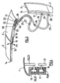
- the roof shown in Figure 1 comprises a rear central roof element 1, generally constituted by the rear window, an intermediate central roof element 2 and a front central roof element 3 joining the upper edge of the windshield.
- the roof according to the invention also comprises a left rear lateral roof element 4, a left front lateral roof element 5, a right rear roof element 6 and a right front lateral roof element 7.
- roof elements therefore connect the upper edge of the windshield to the upper edge of the tailgate tailgate 9 and laterally the upper edges of the side windows of the vehicle (not shown).
- this tailgate 9 is articulated along its edge lower than the chassis of the vehicle according to a transverse axis of rotation 10, and actuable by means of a jack 11 allowing its opening for the insertion of the rear central roof element 1.
- the front central roof element 3 is mounted laterally on sliders 13.
- the front central element 3 is mounted on the sliders 13 via a transverse axis of rotation 14 located at the edge. front of the element 3 and at the front end of the slides 13. This axis of rotation allows movement up and down along the arrow F1 of the rear edge of the element 3.
- Each slider 13 is mounted by means of rollers 15 and 16 on a slide 17.
- the slide 17 has two grooves 18 and 19, the groove 18 receiving the rollers 15 and 16.
- the groove 19 receives two rollers 20 and 21 integral with two fittings 22 and 23 supporting the intermediate central roof element 2.
- Motorization means of any known type allow the sliding of the sliders 13 in the slideways, as well as the sliding of the rollers of the fittings 22 and 23 in these same slideways.
- levers 24 and 25 are articulated about a transverse axis respectively 26 and 27 to the structure of the vehicle at one of their ends. At their other end, these levers are articulated, also about an axis transverse to the slide 17 about axes 28 and 29. These levers 24 and 25 are shown at the top of Figure 3 in the position they adopt when the roof covers the cockpit of the vehicle, and in the lower part of the figure when the roof is stored in the trunk.
- FIG. 1 shows the left side roof elements 4 and 5 and their folding mechanism.
- the right side elements are similar.
- the rear edge of the front side roof element 5 is hinged to the front edge of the rear side roof element 4 around a transverse axis 30.
- the rear edge of the rear side roof element 4 is hinged to a tilting member 31 about an axis 32.
- the axes 30 and 32 are transverse when the roof is, as shown in Figure 2, either in the overlap position or in the folded position, and are substantially vertical when the roof is in storage position as will be discussed below.
- a reinforcing member 33 has one of its ends articulated on the axis 32 and its other end articulated on the axis 30.
- a lever 34 is articulated on the folding member 31 on an axis 35 also transversal but located at a certain distance from the axis 32 and its other end articulated on the roof element 5 about a transverse axis 36 located at a distance from the axis 30.
- the folding member 31 is pivotally mounted relative to the vehicle structure about a longitudinal axis 37.
- Motorization means of known type, and therefore not shown, are provided to actuate the elements described above.
- the passage of the roof from its covering position to its storage position is carried out as follows. Its reverse passage from the storage position to the recovery position is performed in the opposite way.
- the tailgate is rotated about the axis 10 by the action of the cylinder 11 and the roof element 1 is slid into the tailgate 9.
- the levers 33 and 34 then cause the lifting and folding of the roof elements 4 and 5 in the position shown in Figure 2, and a folding around the axis 37 brings the latter elements in the substantially horizontal position of Figure 5 where they are at the back of the elements 2 and 3, superimposed two by two.
- the front roof element (or panel) 40 is mounted on a first slideway 42, which is engaged with a second slideway 44, itself engaged with a third slide 46 carried by the roof element 48 which, in the closed position of the roof above the passenger compartment as in FIG. 7, is located behind the panel 40, at its level, that is to say in a flush position vis-à- screw the surrounding structure of the vehicle (which could be constituted by the elements 4, 5, 6, 7 as in the example of Figure 1 or by the bodywork 50).
- the roof panels 40 and 48 define two substantially flat panels located in front of a rear roof element 52, which typically carries the rear window of the vehicle.
- the part 52 could however consist of a fixed part of the vehicle, that is to say, define a fixed eyewear on the bodywork.
- the roof elements 40, 48 and 52 can be assimilated to the roof elements 3, 2 and 1 respectively of FIG. 1, so that the roof front element 40 therefore comes, in its closed state as in Figure 7, the contact at the front of the transverse strip 54 which limits in the upper part the windshield 56 of the vehicle (see Figure 1).
- the slide system 42, 44, 46 extends substantially substantially parallel to the longitudinal direction of advance 58 of the vehicle.
- the panels 40, 48 must be stored in the trunk of the vehicle, it will be advantageous to provide the third slide 46 is fixedly connected to an arm 60, in the same way that the rear roof element 52 (if mobile) may itself be connected to another arm (not shown), these two hinge arms may correspond at the arms 24, 25 of the solution of FIG. 3 articulated around the transverse axes 26, 27.
- the version presented here is such that, to open the front roof panel 40, it must be slid from the front (AVT) towards the rear (ARR), this sliding causing the lifting of the rear panel 48 so as to release under it a space adapted to receive the substantially axial sliding (almost without level change) of the front panel 40.
- the panel 48 is connected to the slideway 46 (also called “first groove") by arms respectively 53a and 53b respectively rear protruding under it and on each of which articulates a lever (such as 62,64, see below ).
- the roof portion 48 will be raised to allow the passage under it of the front roof portion 40.
- the front roof element 40 is mounted on the front slideway 42, while the rear roof element is slidably mounted on the rear slideway 46, the intermediate slide 44 controlling the movements of the movable panel in height (here the back panel 48).
- the rear roof element 48 will shift upwards along the third slideway 46 to allow the passage under it of the front roof element 40.
- the rear roof element 48 is engaged in the third slide by groups of front and rear levers 62,64 advantageously each bent.
- Each elbow is articulated to the rear roof 48 by an axis of rotation perpendicular to the longitudinal direction 58.
- the end opposite to the axis of rotation of the bend considered is engaged in the third slide 46 by two sliders, such as 66.68.
- the third slide 48 has two deflections 70,72 directed upwards and forwards (towards their free end) and located respectively at the front end and at a short distance from the rear end of the slide.
- the rear panel is in the "flush" position, the bottom of FIGS. 7 and 9, the two slides 66, 68 of each bend are fully engaged in these deflections, by the branch 62b of the lever considered, which ends with the hinge at the roof ( 74) while the other portion 62a of the bend located between the rearmost sliders and the point of articulation of the bend relative to the rear roof element is substantially horizontal along the third slider.
- This position of the elbow makes it possible to have the rear roof in the lower position and at the same level as the front of the rear roof element 52.
- the intermediate slide 44 will come into abutment by a rear surface 76 on the slide 66 then engaged foremost forward and the highest in the forward deflection. 70, to allow upward tilting of the roof element 48 and its drive backwards.
- this second slideway 44 may have at its rear end a contact surface (pusher 76) whose end is curved upwardly and rearwardly. This curved surface will bear on the roller 66 the foremost and the highest and move along the deviation and down. The second rearmost slide 68 will also move along this deflection to engage the substantially horizontal portion of the third slideway. The portion of the elbow between the second slider and the hinge 74 of the roof and the elbow will then shift upward causing the rear roof upwardly and rearwardly.
- the slide 44 also has a hook area 78.
- This hook is located behind said contact surface when said second slide moves rearward; it is therefore placed on the front of the second slideway 44 (see FIG. 10).
- This hooking zone will allow to continue the upward movement of the roof element 48, as well as its "horizontal” drive backwards, over a short distance, adapted to allow the tilting of the front and rear levers 62, 64.
- This hook 78 also makes it possible to drive the same roof element 48 forwards until the beginning of the slide deflection, when the front panel 40 is closed.
- each drive hook 78 advantageously has a drive groove 80 adapted to receive the corresponding slider 66 and drive along the guide 46 concerned, the groove extending to the front by a drive wall 82 adapted to drive the slide backwards along the groove or slideway 46, this groove extending to the rear by a short drive finger 84 leaving an opening 86 for access to the slide, by the rear of the hook.
- the short drive finger will drive the slide 66 (and therefore the panel 48) forward as it engages the groove 46 substantially in said longitudinal direction 58, but disengaging the slide when the latter will engage in the deflection 70 when it meets it, this deviation being for that reason of course then located in the extension of the groove and making with it an angle ⁇ obtuse so that the slide can engage in the direction of its drive (fig .11).
- the front central roof element (or front panel) 100 could be mounted sliding on a first groove 210 of a slide system 700 extending generally substantially parallel to the longitudinal direction 58.
- a second intermediate central roof element (or rear panel) 300 is here slidably mounted on a second groove 230 of the slide 700.
- the roof elements 100,300 are superimposed on each other in such a way that the front roof element 100 passes over the roof element 300 (Fig. 13).
- a hook member 270 On the front edge 100a of the roof element 100 is a hook member 270.
- This roof element is driven backwards by known means which may consist of motorized flexible cables. It is engaged in the first groove 210 by two slides 290,310 spaced by an axial distance L.
- the first slide 290 located furthest forward of the front roof element is engaged in a deflection 210a (corresponding to an accentuation of the slope groove 210) facing the front of the vehicle and down. This said deflection is located at the front end of the groove 210.
- the second slider 310 located furthest from the roof element 100 is engaged in a second rear deflection 210b of the same orientation as the first and remote of the latter of the same length L above.
- the front edge of the roof element 300 has an arm 410 extending downwardly and having a finger or a roller 430 at its lower end.
- the front roof element reaches the horizontal above the roof element 300 (FIG 13)
- the hook 270 located on the front edge of the front central roof element bears on the said finger.
- the hook will then drive rearwardly the roof element 300 and upset it along the two said deviations 230a, 230b, to allow the intermediate central roof element to pass over another even more rear roof element (not shown), the curvature of the slide which extends upwards further ensuring the passage of the front roof element 100 above this roof element further back.
- Figures 12 and 13 also note the shape of the hook 270 which is very similar to that of the hook 78 of Figure 10, with its groove 271 adapted to receive the slide 430 and drive along the corresponding guide, the throat extending, at the front, by the wall 272 adapted to drive rearward (ARR) the slide, along the groove 230a then 230, this groove extending at the rear by the short finger 273 opening an opening access to the slide, from the rear of the hook, so that the finger drives the slide forward as it engages the groove substantially in said longitudinal direction 58, but disengages the slide when the latter engages in the deviation 230a that it meets in the continuity of its forward movement.
- the hook 270 which is very similar to that of the hook 78 of Figure 10, with its groove 271 adapted to receive the slide 430 and drive along the corresponding guide, the throat extending, at the front, by the wall 272 adapted to drive rearward (ARR) the slide, along the groove 230a then 230, this groove extending at the rear by the short finger 2
Abstract
Description
La présente invention concerne un toit escamotable de véhicule selon le préambule de la revendication 1, et plus particulièrement un tel toit comprenant plusieurs panneaux (ou éléments) de toit rigides, dont l'un au moins est déplaçable entre une position dans laquelle des panneaux de toit ferment l'habitacle du véhicule, sur le dessus, et une position dans laquelle ils dégagent une ouverture dans le pavillon. Un toit de ce type est connu du document
Certains toits, dont si nécessaire celui de l'invention, sont escamotables derrière l'habitacle du véhicule, permettant alors de transformer un véhicule du type berline ou coupé en un véhicule du type cabriolet.Some roofs, including if necessary that of the invention, are retractable behind the vehicle interior, allowing then to transform a sedan-type vehicle or coupe into a cabriolet type vehicle.
Une des difficultés rencontrées dans la conception de ce type de toit réside dans le stockage des éléments de toit dans le coffre arrière du véhicule.One of the difficulties encountered in the design of this type of roof lies in the storage of the roof elements in the trunk of the vehicle.
Une autre difficulté réside dans la conception et la réalisation de la cinématique de mouvement des éléments de toit lorsqu'ils sont sur le dessus du toit.Another difficulty lies in the design and realization of the motion kinematics of the roof elements when they are on top of the roof.
C'est pour cela qu'il va être ici question d'un système de toit ouvrant pour un véhicule automobile, ainsi que d'un véhicule ainsi équipé.This is why it will be here question of a sunroof system for a motor vehicle, as well as a vehicle and equipped.
On connaît déjà différents systèmes de toit ouvrant comprenant au moins un panneau de toit avant et un panneau de toit arrière, ces panneaux étant mobiles suivant une direction longitudinale (correspondant à la direction longitudinale d'avance du véhicule) entre une position affleurante dans laquelle les panneaux sont disposés sensiblement au même niveau l'un par rapport à l'autre, le panneau de toit avant étant alors situé devant le panneau de toit arrière, suivant ladite direction longitudinale, et une position décalée en hauteur dans laquelle les panneaux de toit sont disposés l'un au-dessus de l'autre.Various sunroof systems are already known comprising at least one front roof panel and one rear roof panel, these panels being movable in a longitudinal direction (corresponding to the longitudinal direction of advance of the vehicle) between a flush position in which the panels are arranged substantially at the same level relative to each other, the front roof panel being then located in front of the rear roof panel, in said longitudinal direction, and a position shifted in height in which the roof panels are arranged one above the other.
A partir d'un tel système connu, un but est ici de proposer un système de toit ouvrant fiable, relativement simple mécaniquement, d'un prix de revient compatible avec une production en série en liaison avec des constructeurs automobiles, et qui évite les problèmes déjà rencontrés de coordination dans les mouvements des panneaux assurant une cinématique performante et fiable.From such a known system, an aim here is to propose a reliable, relatively simple mechanical sunroof system, at a cost price compatible with mass production in association with automobile manufacturers, and which avoids the problems already encountered coordination in the movements of the panels ensuring a performance and reliable kinematics.
Pour cela, une caractéristique importante prévoit que :
- l'un parmi les panneaux de toit avant et arrière comprend un groupe de leviers avant et un groupe de leviers arrière montés articulés par rapport à ce panneau de toit, pour basculer entre :
- * une position basse dans laquelle le panneau concerné affleure sensiblement une partie environnante de la structure du véhicule,
- * et une position haute dans laquelle ledit panneau concerné est décalé en hauteur par rapport au niveau de sa position affleurante,
- l'un au moins parmi lesdites panneaux de toit comprenant les groupes de leviers et l'autre panneau comprend des moyens d'entraînement pour entraîner les groupes de leviers et l'un des panneaux:
- * soit de l'avant vers l'arrière, sur une distance assurant le passage du panneau de toit de sa position affleurante à sa position décalée en hauteur,
- * soit de l'arrière vers l'avant, sur ladite distance, mais en sens inverse, pour assurer un passage du panneau de toit concerné de sa position décalée vers sa position affleurante, et
- les groupes de leviers engagent, sous la commande des moyens d'entraînement, des guides s'étendant essentiellement sensiblement parallèlement à ladite direction longitudinale, ces guides étant adaptés pour :
- * lors du déplacement commandé de l'avant vers l'arrière des groupes de leviers, guider leur basculement de la position affleurante du panneau correspondant vers sa position décalée,
- * et, lors du déplacement commandé de l'arrière vers l'avant de ces mêmes groupes de leviers, guider leur basculement de la position décalée du panneau correspondant vers sa position, affleurante.
- one of the front and rear roof panels comprises a group of front levers and a group of rear levers mounted articulated with respect to this roof panel, to switch between:
- a low position in which the relevant panel is substantially flush with a surrounding part of the vehicle structure,
- * and a high position in which said concerned panel is offset in height relative to the level of its flush position,
- at least one of said roof panels comprising the groups of levers and the other panel comprises driving means for driving the groups of levers and one of the panels:
- * from front to rear, over a distance ensuring the passage of the roof panel from its flush position to its position offset in height,
- * from the back to the front, over said distance, but in opposite directions, to ensure a passage of the roof panel concerned from its offset position to its flush position, and
- the groups of levers engage, under the control of the drive means, guides extending substantially substantially parallel to said longitudinal direction, these guides being adapted to:
- * during the controlled movement of the lever groups from front to rear, guide their tilting from the flush position of the corresponding panel to its offset position,
- * and, during the controlled displacement of the rear to the front of the same groups of levers, guide their tilting of the offset position of the corresponding panel to its position, flush.
Pour favoriser encore l'obtention des buts fixés ci-avant, avec une mécanique toute à la fois relativement simple, performante et fiable, une autre caractéristique conseille que les groupes de levier comprennent, individuellement, un levier coudé comprenant une première branche articulée en rotation sur le panneau de toit correspondant et reliée fixement par un coude à une deuxième branche, laquelle engage l'un desdits guides, pour son entraînement guidé.To further favor the attainment of the goals set forth above, with a mechanism that is at the same time relatively simple, efficient and reliable, another characteristic advises that the lever groups comprise, individually, a bent lever comprising a first branch articulated in rotation. on the corresponding roof panel and fixedly connected by a bend to a second branch, which engages one of said guides, for its guided training.
Toujours dans le même but, et en tirant parti de l'utilisation déjà connue de moyens de coulissement de type "glissières", une autre caractéristique prévoit que les guides des leviers équipant le(s) panneau(x) de toit concerné(s) comprennent avantageusement des glissières dans lesquelles coulissent ces groupes de levier, les glissières présentant localement des déviations s'étendant obliquement par rapport à l'horizontale et par rapport à ladite direction longitudinale, sur une longueur suffisante pour recevoir, individuellement, une partie d'un desdits groupes de levier, de telle sorte qu'une fois engagés dans ces déviations, les groupes de leviers concernés passent, en pivotant, de l'une de leurs positions haute ou basse vers l'autre.Still for the same purpose, and taking advantage of the already known use of "sliding" type sliding means, another characteristic provides that the guides of the levers equipping the roof panel (s) in question (s) advantageously comprise slides in which these lever groups slide, the slides having locally deviations extending obliquely relative to the horizontal and with respect to said longitudinal direction, over a length sufficient to receive, individually, a portion of a said lever groups, so that once engaged in these deviations, the groups of levers concerned pivot, one of their upper or lower positions to the other.
Si, comme cela est supposé, un intérêt a été trouvé dans l'utilisation des deux caractéristiques qui précèdent, il est par ailleurs conseillé, pour simplifier l'entraînement en coulissement tant vers l'avant que vers l'arrière du (des) panneau (x) de toit concerné(s):
- que la deuxième branche de certains des panneaux est monté coulissant par rapport à l'autre suivant ladite direction longitudinale, le long de secondes rainures desdites glissières,
- que certains au moins des leviers équipant le panneau correspondant comprennent au moins un coulisseau monté glissant dans la première rainure correspondante,
- que lesdits moyens d'entraînement présentent une extrémité avant et une extrémité arrière, -et que ces moyens d'entraînement comprennent un crochet d'entraînement présentant une gorge d'entraînement adaptée pour recevoir ledit coulisseau et l' entraîner le long de la première rainure correspondante, la gorge se prolongeant, à l'avant, par une paroi d'entraînement adapté pour entraîner vers l'arrière le coulisseau correspondant, le long de ladite première rainure, cette gorge se prolongeant à l'arrière par un doigt d'entraînement court ménageant une ouverture d'accès pour le coulisseau, par l'arrière dudit crochet d'entraînement, de telle sorte que le doigt d'entraînement court entraîne le coulisseau vers l'avant tant qu'il engage la première rainure suivant sensiblement ladite direction longitudinale, mais se dégageant du coulisseau lorsque ce dernier s'engage dans la déviation de ladite première rainure qu'il rencontre, cette déviation étant alors située dans le prolongement de la première rainure et faisant avec elle un angle obtus pour que le coulisseau puisse s'y engager dans le sens de son entraînement.
- the second branch of some of the panels is slidably mounted relative to the other in said longitudinal direction, along second grooves of said rails,
- at least some of the levers equipping the corresponding panel comprise at least one slide mounted sliding in the corresponding first groove,
- said drive means have a front end and a rear end, and said drive means comprise a drive hook having a driving groove adapted to receive said slider and drive it along the first groove corresponding, the groove extending, at the front, by a drive wall adapted to drive rearwardly the corresponding slide along said first groove, this groove extending at the rear by a drive finger short manner providing an access opening for the slide, by the rear of said drive hook, so that the short drive finger drives the slide forward as it engages the first groove substantially in said direction longitudinal, but disengaging from the slide when the latter engages in the deflection of said first groove that it encounters, this deviation then being killed in the extension of the first groove and making with it an obtuse angle so that the slide can engage in the direction of his training.
Une telle caractéristique est en particulier applicable aux cas où le panneau avant de toit est monté coulissant par rapport au panneau arrière pour passer sous lui.Such a feature is particularly applicable to cases where the roof front panel is slidably mounted relative to the rear panel to pass under it.
Dans ce cas, on conseille subsidiairement que :
- les coulisseaux soient disposés sur la deuxième branche de certains au moins des leviers,
- que lesdits moyens d'entraînement soient allongés selon la direction longitudinale de déplacement des panneaux de toit l'un par rapport à l'autre,
- et que les déviations de chaque première rainure soient orientées vers le haut, les groupes de levier étant liés au panneau arrière sous lequel s'étend ladite première rainure.
- the sliders are arranged on the second branch of at least some of the levers,
- said driving means are elongated in the longitudinal direction of movement of the roof panels relative to one another,
- and that the deflections of each first groove are oriented upwards, the lever groups being connected to the rear panel under which said first groove extends.
En combinaison avec tout ou partie des caractéristiques qui précèdent concernant cette mécanique de panneaux de toit, on obtient alors un mécanisme fiable et efficace pour un tel mouvement faisant passer l'élément de toit avant sous l'élément de toit arrière.In combination with all or some of the foregoing features relating to this roof panel mechanism, a reliable and efficient mechanism for such a movement passing the front roof element under the rear roof element is thereby obtained.
Tout particulièrement dans ce cas, une autre caractéristique conseille même que les moyens d'entraînement comprennent, vers leur extrémité arrière, un poussoir adapté pour engager au moins un levier du groupe de leviers avant, alors que celui-ci est en position basse et l'entraîner avec lui dans le sens de déplacement vers l'arrière desdits moyens d'entraînement.Particularly in this case, another characteristic even advises that the drive means comprise, towards their rear end, a pusher adapted to engage at least one lever of the group of front levers, while the latter is in the low position and the driving with him in the direction of rearward movement of said drive means.
Toujours dans la même situation, on conseille encore que les moyens d'entraînement du panneau de toit avant comprennent, vers leur extrémité arrière, un deuxième doigt d'entraînement adapté pour engager entièrement, dans les déviations correspondantes, le groupe de leviers avant équipant le panneau de toit arrière, une fois ces leviers dégagés du doigt d'entraînement court correspondant, consécutivement à un coulissement vers l'avant du panneau de toit avant, de manière que le panneau de toit arrière passe alors dans sa position affleurante.Still in the same situation, it is further advised that the drive means of the front roof panel include, towards their rear end, a second drive finger adapted to fully engage, in the corresponding deviations, the group of front levers equipping the rear roof panel, once these levers released from the corresponding short drive finger, following a forward sliding of the front roof panel, so that the rear roof panel then passes to its flush position.
Ce deuxième doigt permet d'assurer, avec une solution simple, fiable et performante, un complet engagement des leviers dans les déviations correspondantes, conduisant ainsi de manière efficace le panneau arrière de toit dans sa position basse, affleurante.This second finger ensures, with a simple, reliable and efficient solution, a complete engaging the levers in the corresponding deviations, thereby effectively driving the roof rear panel to its low, flush position.
Pour par ailleurs satisfaire au problème évoqué en début de description du stockage des éléments de toit dans le coffre arrière du véhicule, il est en outre ici proposé que le toit escamotable comprenne:
- un élément de toit central arrière, un élément de toit central intermédiaire et un élément de toit central avant ;
- un élément de toit latéral arrière gauche, un élément de toit latéral avant gauche, un élément de toit latéral arrière droit, et un élément de toit latéral avant droit;
- des moyens pour faire coulisser l'élément de toit central arrière dans un hayon de coffre arrière ;
- des moyens pour disposer l'élément de toit central intermédiaire et l'élément de toit central avant en position de recouvrement et pour escamoter l'ensemble ainsi obtenu verticalement à l'avant du coffre arrière ;
- des moyens pour disposer l'élément de toit latéral arrière gauche et l'élément de toit latéral avant gauche en position de recouvrement et pour escamoter l'ensemble ainsi obtenu horizontalement dans le coffre arrière à l'arrière de l'ensemble constitué par l'élément de toit central intermédiaire et l'élément de toit central avant ; et
- des moyens pour disposer l'élément de toit latéral arrière droit et l'élément de toit latéral avant droit en position de recouvrement et pour escamoter l'ensemble ainsi obtenu horizontalement dans le coffre au-dessus ou au-dessous de l'ensemble constitué par l'élément de toit latéral arrière gauche et l'élément de toit latéral avant gauche.
- a rear central roof element, an intermediate central roof element and a front central roof element;
- a left rear side roof element, a front left side roof element, a right rear side roof element, and a right front side roof element;
- means for sliding the rear central roof element in a tailgate;
- means for arranging the intermediate central roof element and the front central roof element in the covering position and for retracting the assembly thus obtained vertically at the front of the rear trunk;
- means for arranging the left rear side roof element and the left front side roof element in the overlap position and for retracting the assembly thus obtained horizontally in the rear trunk at the rear of the assembly constituted by the intermediate central roof element and the front central roof element; and
- means for arranging the right rear side roof element and the right front side roof element in the overlapping position and for retracting the assembly thus obtained horizontally in the trunk above or below the assembly constituted by the left rear side roof element and the left front side roof element.
Comme on l'aura compris de ce qui précède, les moyens pour disposer l'élément de toit central intermédiaire et l'élément de toit central avant en position de recouvrement comprendront avantageusement des moyens de coulissement relatif de l'élément de toit central intermédiaire et de l'élément de toit central avant.As will be understood from the foregoing, the means for disposing the intermediate central roof element and the front central roof element in the overlap position will advantageously comprise relative sliding means of the intermediate central roof element and of the front central roof element.
Plus particulièrement, lesdits moyens de coulissement peuvent comprendre au moins une glissière latérale longitudinale sur laquelle est monté l'élément de toit central intermédiaire, et agencée pour coopérer avec un coulisseau sur lequel est monté l'élément de toit central avant.More particularly, said sliding means may comprise at least one longitudinal lateral slide on which is mounted the intermediate central roof element, and arranged to cooperate with a slide on which is mounted the front central roof element.
Il sera alors possible de faire coulisser l'élément de toit central avant pour l'amener au niveau de l'élément de toit central intermédiaire, et ainsi de dégager la partie avant du toit.It will then be possible to slide the front central roof element to bring it to the intermediate central roof element, and thus to clear the front part of the roof.
On observera que, par "longitudinal", on entend généralement parallèle à la direction avant/arrière du véhicule. De même, par "transversal", on entend généralement perpendiculaire au plan de symétrie du véhicule.It will be observed that "longitudinal" means generally parallel to the forward / backward direction of the vehicle. Similarly, "transversal" generally means perpendicular to the plane of symmetry of the vehicle.
Encore plus particulièrement, ledit coulisseau peut comporter des galets aptes à se déplacer dans une première rainure de ladite glissière.Even more particularly, said slide may comprise rollers adapted to move in a first groove of said slide.
Par ailleurs, l'élément de toit central intermédiaire peut être monté sur des galets aptes à se déplacer dans une deuxième rainure de ladite glissière.Furthermore, the intermediate central roof element can be mounted on rollers able to move in a second groove of said slide.
Egalement dans un mode de réalisation particulier, les moyens pour escamoter l'ensemble constitué par l'élément de toit central intermédiaire et l'élément de toit central avant verticalement à l'avant du coffre arrière comprennent au moins deux leviers articulés à une de leurs extrémités sur la structure du véhicule et formant un quadrilatère déformable.Also in a particular embodiment, the means for retracting the assembly constituted by the intermediate central roof element and the front central roof element vertically at the front of the rear trunk comprise at least two levers hinged to one of their ends on the vehicle structure and forming a deformable quadrilateral.
Dans le cas d'un montage à glissière, lesdits leviers peuvent être articulés à leur autre extrémité sur ladite glissière.In the case of a slide assembly, said levers can be articulated at their other end to said slide.
Dans un mode de réalisation particulier, les moyens pour disposer l'élément de toit latéral arrière gauche (respectivement droit) et l'élément de toit latéral avant gauche (respectivement droit) en position de recouvrement comprennent une articulation autour d'un axe transversal entre le bord avant de l'élément de toit latéral arrière gauche (respectivement droit) et le bord arrière de l'élément de toit latéral avant gauche (respectivement droit).In a particular embodiment, the means for arranging the left rear side roof element (respectively straight) and the left front side roof element (respectively right) in the overlap position comprise a hinge about a transverse axis between the front edge of the left rear side roof element (respectively right) and the rear edge of the left front side roof element (respectively right).
La partie latérale du toit se replie donc autour d'un axe intermédiaire.The lateral part of the roof thus folds around an intermediate axis.
Egalement dans un mode de réalisation particulier, les moyens pour escamoter horizontalement dans le coffre arrière l'ensemble constitué par l'élément de toit latéral arrière gauche (respectivement droit) et l'élément de toit latéral avant gauche (respectivement droit) comprennent un organe de rabattement articulé sur la structure du véhicule autour d'un axe longitudinal entre une position de recouvrement et une position de rangement, et l'élément de toit latéral arrière gauche (respectivement droit) est articulé au voisinage de son bord arrière sur ledit organe de rabattement autour d'un axe généralement transversal lorsque ledit organe de rabattement est dans sa position de recouvrement et généralement vertical lorsque ledit organe de rabattement est dans sa position de rangement.Also in a particular embodiment, the means for horizontally retracting into the trunk the assembly consisting of the left rear side roof element (respectively straight) and the front left side roof element (respectively right) comprise an element articulated folding on the vehicle structure about a longitudinal axis between a covering position and a storage position, and the left rear side roof element (respectively straight) is articulated in the vicinity of its rear edge on said member of folding around a generally transverse axis when said folding member is in its overlapping position and generally vertical when said folding member is in its storage position.
Plus particulièrement, les moyens pour disposer l'élément de toit latéral arrière gauche (respectivement droit) et l'élément de toit latéral avant gauche (respectivement droit) en position de recouvrement peuvent comprendre au moins un levier ayant une de ses extrémités articulée sur l'organe de rabattement à une certaine distance de l'axe d'articulation de l'élément de toit latéral arrière gauche (respectivement droit) et son autre extrémité articulée sur l'élément de toit latéral avant gauche (respectivement droit) à une certaine distance de l'axe d'articulation de l'élément de toit latéral arrière gauche (respectivement droit).More particularly, the means for arranging the left rear side roof element (respectively straight) and the front left side roof element (respectively right) in the overlap position may comprise at least one lever having one of its ends articulated on the 'folding organ at a certain distance from the axis of articulation of the left rear lateral roof element (respectively right) and its other end articulated on the front left side roof element (respectively right) at a certain distance from the axis of articulation of the left-side rear roof element (respectively straight).
Une description encore plus détaillée du présent sujet suit, de façon exemplaire en référence aux dessins schématiques annexés dans lesquels :
- la figure 1 est une vue en perspective d'un toit ouvrant utilisable ici ;
- la figure 2 est une vue de côté des moyens de rabattement des éléments latéraux du toit de la fig.1 en position de recouvrement et en position intermédiaire de rabattement ;
- la figure 3 est une vue en perspective des moyens de rangement des éléments centraux du toit dans leur position de recouvrement et dans leur position de rangement ;
- la figure 4 est une vue en coupe des glissières de la fig.3 ;
- la figure 5 est une vue de côté des éléments du toit en position de rangement ;
- la figure 6 est une vue de l'arrière de ces éléments en position de rangement,
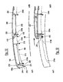
- la figure 7 montre un autre mécanisme de toit permettant le coulissement relatif d'un élément (ou panneau) de toit avant par rapport à un élément (ou panneau) de toit arrière, les deux panneaux étant en position fermée, sensiblement au même niveau l'un devant l'autre sur la figure 7, tandis que le panneau avant est passé sous le panneau arrière sur la figure 8,
- les figures 9, 10 et 11 montrent trois situations différentes de coulissement et de positions des panneaux avant et arrière concernés,
- et les figures 12 et 13 montrent une alternative de réalisation dans laquelle le panneau avant de toit passe par dessus le panneau arrière lorsqu'il recule, libérant ainsi une ouverture au-dessus de l'habitacle, dans le toit.
- Figure 1 is a perspective view of a sunroof usable here;
- Figure 2 is a side view of the folding means of the lateral elements of the roof of Fig.1 in the overlap position and intermediate position of folding;
- Figure 3 is a perspective view of the storage means of the central elements of the roof in their covering position and in their storage position;
- Figure 4 is a sectional view of the slides of Figure 3;
- Figure 5 is a side view of the roof elements in the storage position;
- FIG. 6 is a view from the rear of these elements in the storage position,
- FIG. 7 shows another roof mechanism allowing the relative sliding of a front roof element (or panel) with respect to a rear roof element (or panel), the two panels being in the closed position, substantially at the same level one in front of the other in Figure 7, while the front panel has passed under the rear panel in Figure 8,
- FIGS. 9, 10 and 11 show three different situations of sliding and positions of the front and rear panels concerned,
- and Figures 12 and 13 show an alternate embodiment in which the roof front panel passes over the rear panel as it recedes, thereby releasing an opening above the passenger compartment in the roof.
Le toit montré à la figure 1 comprend un élément de toit central arrière 1, généralement constitué par la vitre arrière, un élément de toit central intermédiaire 2 et un élément de toit central avant 3 rejoignant le bord supérieur du pare-brise. Le toit selon l'invention comporte également un élément de toit latéral arrière gauche 4, un élément de toit latéral avant gauche 5, un élément de toit arrière droit 6 et un élément de toit latéral avant droit 7.The roof shown in Figure 1 comprises a rear
Ces éléments de toit relient par conséquent d'avant en arrière le bord supérieur du pare-brise au bord supérieur du hayon 9 de coffre arrière et latéralement les bords supérieurs des vitres latérales du véhicule (non représentées).These roof elements therefore connect the upper edge of the windshield to the upper edge of the
Des moyens connus, et par conséquent non décrits ci-après, permettent le coulissement de l'élément de toit central arrière, et plus particulièrement de sa vitre, dans le hayon 9. Par ailleurs, ce hayon 9 est articulé le long de son bord inférieur au châssis du véhicule selon un axe de rotation transversal 10, et actionnable au moyen d'un vérin 11 permettant son ouverture pour l'insertion de l'élément de toit central arrière 1.Known means, and therefore not described below, allow the sliding of the rear central roof element, and more particularly of its window, in the
Les agencements décrits ci-après sont généralement du même type de chaque côté du véhicule.The arrangements described below are generally of the same type on each side of the vehicle.
Comme montré à la figure 3, l'élément de toit central avant 3 est monté latéralement sur des coulisseaux 13. L'élément central avant 3 est monté sur les coulisseaux 13 par l'intermédiaire d'un axe de rotation 14 transversal situé au bord avant de l'élément 3 et à l'extrémité avant des coulisseaux 13. Cet axe de rotation permet un mouvement vers le haut et vers le bas selon la flèche F1 du bord arrière de l'élément 3.As shown in FIG. 3, the front central roof element 3 is mounted laterally on
Chaque coulisseau 13 est monté par l'intermédiaire de galets 15 et 16 sur une glissière 17. La glissière 17 comporte deux rainures 18 et 19, la rainure 18 recevant les galets 15 et 16.Each
La rainure 19 reçoit deux galets 20 et 21 solidaires de deux ferrures 22 et 23 supportant l'élément de toit central intermédiaire 2.The
Des moyens de motorisation de tout type connu permettent le coulissement des coulisseaux 13 dans les glissières, ainsi que le coulissement des galets des ferrures 22 et 23 dans ces mêmes glissières.Motorization means of any known type allow the sliding of the
Deux leviers 24 et 25 sont articulés autour d'un axe transversal respectivement 26 et 27 à la structure du véhicule à une de leurs extrémités. A leur autre extrémité, ces leviers sont articulés, également autour d'un axe transversal à la glissière 17 autour d'axes 28 et 29. Ces leviers 24 et 25 sont représentés en haut de la figure 3 dans la position qu'ils adoptent lorsque le toit recouvre l'habitacle du véhicule, et en partie basse de la figure lorsque le toit est rangé dans le coffre arrière.Two
La figure 2 montre les éléments de toit latéraux gauches 4 et 5 ainsi que leur mécanisme de repliement. Les éléments latéraux droits sont similaires.Figure 2 shows the left
Le bord arrière de l'élément de toit latéral avant 5 est articulé sur le bord avant de l'élément de toit latéral arrière 4 autour d'un axe transversal 30. Le bord arrière de l'élément de toit latéral arrière 4 est articulé sur un organe de basculement 31 autour d'un axe 32. Les axes 30 et 32 sont transversaux lorsque le toit est, comme représenté à la figure 2, soit en position de recouvrement soit en position de repliement, et sont sensiblement verticaux lorsque le toit est en position de rangement comme cela sera exposé ci-après.The rear edge of the front
Un organe de renfort 33 a une de ses extrémités articulée sur l'axe 32 et son autre extrémité articulée sur l'axe 30. Un levier 34 est articulé sur l'organe de rabattement 31 sur un axe 35 également transversal mais situé à une certaine distance de l'axe 32 et son autre extrémité articulée sur l'élément de toit 5 autour d'un axe transversal 36 situé à une certaine distance de l'axe 30.A reinforcing
L'organe de rabattement 31 est monté pivotant par rapport à la structure du véhicule autour d'un axe 37 longitudinal.The folding member 31 is pivotally mounted relative to the vehicle structure about a longitudinal axis 37.
Des moyens de motorisation de type connu, et donc non représentés, sont prévus pour actionner les éléments décrits ci-dessus.Motorization means of known type, and therefore not shown, are provided to actuate the elements described above.
Le passage du toit de sa position de recouvrement à sa position de rangement s'effectue de la façon suivante. Son passage inverse de la position de rangement à la position de recouvrement s'effectue de la manière inverse.The passage of the roof from its covering position to its storage position is carried out as follows. Its reverse passage from the storage position to the recovery position is performed in the opposite way.
En premier lieu, le hayon est ouvert par rotation autour de l'axe 10 par l'action du vérin 11 et l'élément de toit 1 est coulissé dans le hayon 9.In the first place, the tailgate is rotated about the
L'élément 3 est ensuite basculé vers le bas autour de l'axe 14 puis est coulissé sous l'élément 2. Les leviers 25 et 26 sont ensuite basculés de manière à amener les éléments 2 et 3 dans la position représentée au bas de la figure 3 où ils se trouvent en position verticale à l'avant du coffre arrière du véhicule.The element 3 is then swung down around the
Les leviers 33 et 34 provoquent ensuite le relevage et le pliage des éléments de toit 4 et 5 dans la position représentée à la figure 2, puis un rabattement autour de l'axe 37 amène ces derniers éléments dans la position sensiblement horizontale de la figure 5 où ils se trouvent à l'arrière des éléments 2 et 3, superposés deux par deux.The
Dans le mode de réalisation des figures 7 à 12, l'élément (ou panneau) de toit avant 40 est monté sur une première glissière 42, laquelle est engagée avec une deuxième glissière 44, elle même engagée avec une troisième glissière 46 portée par l'élément de toit 48 lequel, en position fermée du toit au-dessus de l'habitacle comme sur la figure 7, est situé derrière le panneau 40, à son niveau, c'est-à-dire en position affleurante vis-à-vis de la structure environnante du véhicule (qui pourrait être constitué par les éléments 4, 5, 6, 7 comme dans l'exemple de la fig. 1 ou par la carrosserie 50).In the embodiment of Figures 7 to 12, the front roof element (or panel) 40 is mounted on a
Les panneaux de toit 40 et 48 définissent deux panneaux sensiblement plans situés devant un élément de toit arrière 52, lequel porte typiquement la lunette arrière du véhicule.The
Eventuellement, la pièce 52 pourrait toutefois consister en une partie fixe du véhicule, c'est-à-dire définir une lunette fixe sur la carrosserie.Optionally, the
Cela étant, hormis,dans cette situation, on peut sur la figure 7 assimiler les éléments de toit 40, 48 et 52 aux éléments de toit respectivement 3, 2 et 1 de la figure 1, de sorte que l'élément avant de toit 40 vient donc, dans son état fermé comme sur la figure 7, au contact à l'avant du bandeau transversal 54 qui limite en partie supérieure le pare-brise 56 du véhicule (voir figure 1).However, in this situation, in FIG. 7, the
A noter également que pour assurer le déplacement relatif des panneaux 40, 48, le système de glissières 42, 44, 46 s'étend essentiellement sensiblement parallèlement à la direction longitudinale d'avance 58 du véhicule.Note also that to ensure the relative movement of the
Si, une fois placés dans leur position superposée de la figure 8, les panneaux 40, 48 doivent être rangés dans le coffre arrière du véhicule, on prévoira avantageusement que la troisième glissière 46 soit liée fixement à un bras 60, de la même manière que l'élément arrière de toit 52 (s'il est mobile) pourra être lui-même relié à un autre bras (non représenté), ces deux bras d'articulation pouvant correspondre aux bras 24, 25 de la solution de la figure 3, articulés autour des axes transversaux 26, 27.If, once placed in their superimposed position in FIG. 8, the
Comme on peut le constater au vu des figures 7 à 11, la version présentée ici est telle que, pour ouvrir le panneau de toit avant 40, il faut le faire coulisser de l'avant (AVT) vers l'arrière (ARR), ce coulissement provoquant l'élévation du panneau arrière 48 de manière à libérer sous lui un espace adapté pour recevoir le glissement sensiblement axial (quasiment sans changement de niveau) du panneau avant 40.As can be seen from FIGS. 7 to 11, the version presented here is such that, to open the
Le panneau 48 est lié à la glissière 46 (également appelée « première rainure ») par des bras respectivement avant 53a et arrière 53b faisant saillie sous lui et sur chacun desquels s'articule un levier (tel que 62,64, voir ci-après).The
Ainsi, la partie de toit 48 va se surélever pour permettre le passage sous elle de la partie du toit avant 40. Une fois ces parties de toits avant et arrière 40, 48 superposées l'une sur l'autre en position sensiblement horizontale, elles pourront pivoter chacune selon le bras d'entraînement dans le coffre de rangement pour venir se positionner par exemple sensiblement à la verticale.Thus, the
Comme déjà indiqué, l'élément de toit avant 40 est monté sur la glissière avant 42, tandis que l'élément de toit arrière est monté coulissant sur la glissière arrière 46, la glissière intermédiaire 44 commandant les mouvements du panneau mobile en hauteur (ici le panneau arrière 48).As already indicated, the
Lors de la superposition des éléments de toit 40,48, l'élément de toit arrière 48 va se décaler vers le haut le long de la troisième glissière 46 pour permettre le passage sous lui de l'élément de toit avant 40.During the superposition of the
Comme montré aux figures 9 à 11, l'élément de toit arrière 48 est donc engagé dans la troisième glissière par des groupes de leviers avant et arrière 62,64 avantageusement chacun coudés. Chaque coude est articulé au toit arrière 48 par un axe de rotation perpendiculaire à la direction longitudinale 58. L'extrémité opposée à l'axe de rotation du coude considéré est engagé dans la troisième glissière 46 par deux coulisseaux, tels que 66,68.As shown in Figures 9 to 11, the
Lorsque les éléments de toit 40,48 sont dans leur position fermée de la figure 7, ces éléments sont au même niveau.When the
La troisième glissière 48 comporte deux déviations, 70,72 orientées vers le haut et vers l'avant (en direction de leur extrémité libre) et situées respectivement à l'extrémité avant et à faible distance de l'extrémité arrière de la glissière .Lorsque le panneau arrière est en position « affleurante », basse des figures 7 et 9, les deux coulisseaux 66,68 de chaque coude sont totalement engagés dans ces déviations, par la branche 62b du levier considéré qui se termine par l'articulation au toit (en 74), tandis que l'autre partie 62a du coude située entre les coulisseaux le plus en arrière et le point d'articulation du coude par rapport à l'élément de toit arrière est sensiblement horizontale le long de la troisième glissière. Cette position du coude permet d'avoir le toit arrière en position basse et au même niveau que l'avant de l'élément de toit arrière 52.The
Lors du coulissement arrière du panneau 40, la glissière intermédiaire 44 va venir en appui par une surface arrière 76 sur le coulisseau 66 alors engagé le plus en avant et le plus haut dans la déviation avant 70, pour permettre le basculement vers le haut de l'élément de toit 48 et son entraînement vers l'arrière.During the rear sliding of the
Ainsi, cette deuxième glissière 44 peut comporter à son extrémité arrière une surface de contact (poussoir 76) dont l'extrémité est courbe vers le haut et vers l'arrière. Cette surface courbe va venir en appui sur le galet 66 le plus en avant et le plus haut et le déplacer le long de la déviation et vers le bas. Le deuxième coulisseau 68 le plus en arrière va également se déplacer le long de cette déviation pour s'engager dans la partie sensiblement horizontale de la troisième glissière. La partie du coude située entre le deuxième coulisseau et l'articulation 74 du toit et du coude va alors se décaler vers le haut entraînant le toit arrière vers le haut et vers l'arrière.Thus, this
La glissière 44 comporte également une zone formant crochet 78. Ce crochet est situé en arrière de la dite surface de contact lorsque que la dite deuxièmes glissière se déplace vers l'arrière ; il est donc placé sur l'avant de la deuxième glissière 44 (voir fig.l0). Cette dite zone de crochetage va permettre de continuer le mouvement de montée de l'élément de toit 48, ainsi que son entraînement « horizontal » vers l'arrière, sur une courte distance, adaptée pour permettre le basculement des leviers avant et arrière 62, 64. Ce crochet 78 permet également d'entraîner ce même élément de toit 48 vers l'avant jusqu'au début de la déviation de glissière, lorsque l'on referme le panneau avant 40.The
Pour favoriser ce coulissement dans les deux sens, chaque crochet d'entraînement 78 présente avantageusement une gorge d'entraînement 80 adaptée pour recevoir le coulisseau 66 correspondant et l'entraîner le long du guide 46 concerné, la gorge se prolongeant, à l'avant, par une paroi d'entraînement 82 adaptée pour entraîner vers l'arrière le coulisseau, le long de la rainure ou glissière 46, cette gorge se prolongeant à l'arrière par un doigt d'entraînement court 84 ménageant une ouverture 86 d'accès pour le coulisseau, par l'arrière du crochet. Ainsi, le doigt d'entraînement court va entraîner le coulisseau 66 (et donc le panneau 48) vers l'avant tant qu'il engagera la rainure 46 suivant sensiblement ladite direction longitudinale 58, mais se dégageant du coulisseau lorsque ce dernier s'engagera dans la déviation 70 lorsqu'il la rencontrera, cette déviation étant pour cela bien entendu alors située dans le prolongement de la rainure et faisant avec elle un angle α obtus pour que le coulisseau puisse s'y engager dans le sens de son entraînement (fig.11).To promote this sliding in both directions, each
De plus une autre de surface de contact 88 s'étendant vers le bas et solidaire de la deuxième glissière 44 est située en avant de ladite première zone de contact 76. Cette deuxième zone de contact se trouve sur la partie arrière de la glissière 46 (également appelée première rainure). Dans un déplacement vers l'avant du panneau 40, lorsque le coulisseau 66 le plus en avant du levier 62 se trouve engagé dans la déviation 70 de la glissière 46 et que ce coulisseau se trouve par ailleurs dégagé du crochet 78, la deuxième surface de contact (ou doigt d'entraînement) 88 vient alors en appui sur le coulisseau 68 le plus en arrière pour engager entièrement les deux coulisseaux dans cette déviation et ainsi positionner la panneau de toit 48 dans sa position fermée et basse, au même niveau que l'avant de l'élément 52 et le panneau avant 40.In addition, another
Pour d'autres détails concernant la disposition relative des glissières (ou rainures) et leur possible commande motorisée, on se reportera à
Comme illustré aux figures 12 et 13, dans une alternative de réalisation, l'élément de toit central avant (ou panneau avant) 100 pourrait être monté coulissant sur une première rainure 210 d'un système de glissières 700 s'étendant globalement sensiblement parallèlement à la direction longitudinale 58. Un deuxième élément de toit central intermédiaire (ou panneau arrière) 300 est ici monté coulissant sur une deuxième rainure 230 de la glissière 700.As illustrated in FIGS. 12 and 13, in an alternative embodiment, the front central roof element (or front panel) 100 could be mounted sliding on a
Dans ce cas, les éléments de toit 100,300 viennent se superposés les uns sur les autres de telle manière que l'élément de toit avant 100 passe au-dessus de l'élément de toit 300 (fig. 13).In this case, the roof elements 100,300 are superimposed on each other in such a way that the
La glissière 7 peut être fixée à la structure 53 du véhicule, latéralement le long de barreaux fixes de toit s'étendant longitudinalement au moins le long des bords latéraux de l'ouverture ménagée dans le pavillon du véhicule pour loger le toit ouvrant.The slide 7 can be fixed to the
Sur le bord avant 100a de l'élément de toit 100 se situe un élément formant crochet 270.On the
Cet élément de toit est entraîné vers l'arrière par des moyens connus qui peuvent consister en des câbles flexibles motorisés. Il est engagé dans la première rainure 210 par deux coulisseaux 290,310 espacés d'une distance axiale L. Le premier coulisseau 290 situé le plus en avant de l'élément de toit avant est engagé dans une déviation 210a (correspondant à une accentuation de la pente de la rainure 210) orientée vers l'avant du véhicule et vers le bas. Cette dite déviation se situe à l'extrémité avant de la rainure 210. Le second coulisseau 310 situé le plus en arrière de l'élément de toit 100 est quant à lui engagé dans une seconde déviation arrière 210b de même orientation que la première et distante de cette dernière de la même longueur L précitée. Lorsque le toit avant 100 est entraîné vers l'arrière il est décalé vers le haut grâce à l'orientation de la première déviation 210a, ainsi qu'à l'orientation de la deuxième déviation 210b. La courbure de la rainure 210 permet alors le passage de l'élément de toit avant au-dessus de l'élément de toit 300.This roof element is driven backwards by known means which may consist of motorized flexible cables. It is engaged in the
Lorsque l'élément de toit 100 coulisse vers l'arrière, le coulisseau 290 se déplace dans la rainure 210 et, au niveau de la déviation 210b, ce coulisseau se déplace sur un levier basculant alors en position inclinée vers le bas, jusqu'à faire basculer ce levier vers le haut de manière que sa partie arrière obture l'extrémité supérieure de la déviation, après que le coulisseau 310 en soit déjà sorti. On comprend que ce système du guidage sélectif à levier basculant à l'endroit de l'autre déviations arrière 230b en liaison avec le coulisseau correspondant 350. En outre, lors du déploiement des panneaux de toit vers leur position fermée au-dessus de l'habitacle, le cheminement inverse des coulisseaux avant de chaque panneau opère le basculement retour des leviers concernés, avant engagement des coulisseaux arrière associés dans les déviations correspondantes.When the
L'élément de toit 300 est monté sur la deuxième rainure 230 par deux coulisseaux 330,350 espacés eux aussi d'une longueur L. Le premier coulisseau 330 situé le plus en avant de cet élément de toit est engagé dans la déviation 230a orientée vers l'avant du véhicule et vers le bas. Cette déviation se situe à l'extrémité avant de la deuxième rainure 230 de la glissière. Le second coulisseau 350 situé le plus en arrière de l'élément de toit 300 est quant à lui engagé dans la seconde déviation 230b de même orientation que la première et distante d'elle de la même longueur L. Lorsque le toit 300 est entraîné vers l'arrière par l'élément de toit avant, il est décalé vers le haut grâce à l'orientation des déviations 230a,230b.The
Le bord avant de l'élément de toit 300 comporte un bras 410 s'étendant vers le bas et comportant ,à son extrémité basse, un doigt ou un galet 430. Lorsque l'élément de toit avant arrive à l'horizontale au-dessus de l 'élément de toit 300 (fig. 13), le crochet 270 situé sur le bord avant la de l'élément de toit central avant vient en appui sur le dit doigt. Le crochet va alors entraîner vers l'arrière l'élément de toit 300 et le décaler vers le haut le long des deux dites déviations 230a,230b, pour permettre le passage de l'élément de toit central intermédiaire au-dessus d'un autre élément de toit encore plus arrière (non représenté), la courbure de la glissière qui s'étend vers le haut assurant par ailleurs le passage de l'élément de toit avant 100 au-dessus de cet élément de toit plus arrière.The front edge of the
Sur les figures 12 et 13 on notera également la forme du crochet 270 qui est très comparable à celle du crochet 78 de la figure 10, avec sa gorge 271 adaptée pour recevoir le coulisseau 430 et l'entraîner le long du guide correspondant, la gorge se prolongeant, à l'avant, par la paroi 272 adaptée pour entraîner vers l'arrière (ARR) le coulisseau, le long de la rainure 230a puis 230, cette gorge se prolongeant à l'arrière par le doigt court 273 ménageant une ouverture d'accès pour le coulisseau, par l'arrière du crochet, de telle sorte que ce doigt entraîne le coulisseau vers l'avant tant qu'il engage la rainure suivant sensiblement ladite direction longitudinale 58, mais se dégage du coulisseau lorsque ce dernier s'engage dans la déviation 230a qu'il rencontre dans la continuité de son mouvement vers l'avant.Figures 12 and 13 also note the shape of the
Claims (9)
- Retractable roof system for a motor vehicle equipped with a structure (50), the retractable roof system comprising at least a front roof panel (3, 40, 100) and a rear roof panel (2, 48, 300), said roof panels being movable in relation to each other along a longitudinal direction (58) between:· a flush position in which the panels are placed substantially at the same level as each other, the front roof panel thus being located in front of the rear roof panel, along said longitudinal direction; and· an off-set position in an upward direction in which the roof panels are placed at least partially one on top of the other;characterised in that :
one of the front and rear panels comprises a group of pivotally mounted front levers (62, 330) and a group of pivotally mounted rear levers (64, 350), so as to tip over between:- a low position in which said one panel is substantially flush with a surround part of the structure (50) of the vehicle;- and a high position in which said one panel is off-set in an upward direction in relation to the level of its flush position;· said groups of front levers (62, 330) and rear levers (64,350) are pivotally mounted in relation to said roof panel (48, 300) which comprises them ;at least one of said roof panels (40, 100, 48, 300), namely the roof panel (48,300) which comprises the lever groups (62, 64, 330, 350) and the other panel (40, 100), comprises driving means (76, 78, 88, 270) for driving the lever groups and said other panel:- either from the front towards the rear, along a distance ensuring said roof panel moves from its flush position to its off-set position in an upward direction;- or from the rear towards the front, along said distance, but in the opposite direction, to ensure the same roof panel moves from its off-set position to its flush position; and· under the control of the driving means (76, 78, 88, 270), the lever groups (62, 64, 320, 350) engage guides (42, 44, 46, 230) extending essentially substantially parallel to said longitudinal direction, these guides being adapted for:- during the controlled displacement of the lever groups from the front towards the rear, guiding their tipping over movement from the flush position of the corresponding panel to its off-set position; and- during the controlled displacement of said lever groups from the rear towards the front, guiding their tipping over movement from the off-set position of the corresponding panel towards its flush position. - Retractable roof system as set forth in claim 1, characterised in that the lever groups (62, 64) individually comprise a curved lever comprising a first arm (62a) rotatingly articulated on the corresponding roof panel (48) and firmly attached via an elbow to a second arm (62b), which engages one of said guides (42, 44, 46), in order to guidingly drive it.
- Retractable roof system as set forth in claim 1 or 2, characterised in that the guides comprise runners equipped with first grooves (46) in which the lever groups (62, 64) slide, the runners locally having deflected slips (70, 72) extending obliquely in relation to the horizontal and in relation to said longitudinal direction, along a length sufficient to receive, individually, a part of said lever groups, so that once engaged in these deflected slips, the lever groups in question move, by pivoting, from one of their high or low positions towards the other position.
- Retractable roof system as set forth in claim 3, characterised in that:- one of the panels (40) is slidingly mounted in relation to the other (48) along said longitudinal direction (58), along second grooves (42, 44) of said runners;- at least some of the levers fitted to the corresponding panel at least comprise a slider (66) slidingly mounted in the first corresponding groove; and- these driving means comprise a driving hook (78) bearing a driving recess (80) adapted for receiving said slider (66) and driving it along the corresponding first groove (46), the recess extending frontwards via a driving wall (82) adapted for driving the corresponding slider backwards, along said first groove (46), this recess extending backwards via a short driving pin (84) making an inlet (86) for the slider, via the rear of said driving hook, so that the short driving pin drives the slider (66) forward as long as it engages the first groove (46) substantially along said longitudinal direction, but extricating from the slider when the latter engages in the deflected slip (70, 72) of said first groove that it encounters, this deflected slip thus being located in the extension of the first groove and making an obtuse angle (α) with it so that the slider can engage in the direction of its drive.
- Retractable roof system as set forth in claim 4,
characterised in that:- the sliders (66, 68) are placed on the second arm (62b) of at least some of the levers (62, 64);- said driving means (76, 78, 88) extend along said longitudinal direction; and- the front panel (40) is slidingly mounted in relation to the rear panel (48) in order to move under it, the deflected slips (70, 72) of each first groove (46) being, for this purpose, oriented upwards and the lever groups being linked to the rear panel under which the first groove extends. - Retractable roof system as set forth in any one of the previous claims, characterised in that the driving means comprise, towards their rear end, a push button (76) adapted for engaging at least one lever from the lever groups (62, 64), when said lever is in the low position, and of driving it along with itself in the direction of backwards displacement of said driving means (76, 78, 88).
- Retractable roof system as set forth in claim 5 or in claim 6 depending on claim 4, characterised in that, the front roof panel (40) being slidingly mounted in relation to the rear panel (48) in order to move under it, the driving means of the front roof panel comprise, towards their rear end, a second driving pin (88) adapted for fully engaging, in the corresponding deflected slips, the second arm of the front lever group fitted to the rear roof panel, once these levers are free from the corresponding short driving pin, consecutively with a forward sliding of the front roof panel, so that the rear roof panel then moves into its flush position.
- Retractable roof system as set forth in claim 3, characterised in that, the front roof panel (40) being slidingly mounted in relation to the rear panel (48) in order to move under it, the driving means of the front roof panel comprise, towards their rear end, a second driving pin (88) adapted for fully engaging, in the corresponding deflected slips, the front lever group fitted to the rear roof panel, consecutively with a forward sliding of the front roof panel, so that the rear roof panel then moves into its flush position.
- Motor vehicle equipped with a retractable roof system as set forth in one of the previous claims.
Applications Claiming Priority (4)
| Application Number | Priority Date | Filing Date | Title |
|---|---|---|---|
| FR0308695A FR2857624A1 (en) | 2003-07-16 | 2003-07-16 | Vehicle opening roof system comprises front and rear roof panels able to move relative to each other between flush position and raised position located one above other |
| FR0308694A FR2857623A1 (en) | 2003-07-16 | 2003-07-16 | Retractable roof for motor vehicle includes solid panels supported on pivot arms enabling motorised retraction into boot space |
| FR0309792A FR2851745B1 (en) | 2003-02-28 | 2003-08-08 | OPENING ROOF SYSTEM WITH SUPERPOSABLE PANELS AND VEHICLE THUS EQUIPPED |
| PCT/FR2004/001884 WO2005007434A2 (en) | 2003-07-16 | 2004-07-16 | Sliding roof system with stackable panels and vehicle equipped therewith |
Publications (2)
| Publication Number | Publication Date |
|---|---|
| EP1644213A2 EP1644213A2 (en) | 2006-04-12 |
| EP1644213B1 true EP1644213B1 (en) | 2007-06-13 |
Family
ID=34084153
Family Applications (1)
| Application Number | Title | Priority Date | Filing Date |
|---|---|---|---|
| EP04767708A Not-in-force EP1644213B1 (en) | 2003-07-16 | 2004-07-16 | Sliding roof system with stackable panels and vehicle equipped therewith |
Country Status (6)
| Country | Link |
|---|---|
| US (1) | US7360828B2 (en) |
| EP (1) | EP1644213B1 (en) |
| JP (1) | JP2007516120A (en) |
| AT (1) | ATE364519T1 (en) |
| DE (1) | DE602004007000T2 (en) |
| WO (1) | WO2005007434A2 (en) |
Families Citing this family (4)
| Publication number | Priority date | Publication date | Assignee | Title |
|---|---|---|---|---|
| DE102004018606B4 (en) * | 2004-04-16 | 2011-06-09 | Wilhelm Karmann Gmbh | Roof structure for a to open rigid vehicle roof |
| US7658797B2 (en) * | 2005-03-22 | 2010-02-09 | Nova Chemicals Inc. | Lightweight concrete compositions |
| JP2007238074A (en) * | 2006-02-10 | 2007-09-20 | Aisin Seiki Co Ltd | Vehicular roof automatic opening/closing device |
| DE102009022195A1 (en) * | 2009-05-20 | 2010-11-25 | Magna Car Top Systems Gmbh | Hood frame for a folding roof of a passenger car |
Family Cites Families (7)
| Publication number | Priority date | Publication date | Assignee | Title |
|---|---|---|---|---|
| NL8701492A (en) * | 1987-06-25 | 1989-01-16 | Vermeulen Hollandia Octrooien | OPEN ROOF CONSTRUCTION FOR A VEHICLE. |
| FR2730958B1 (en) | 1995-02-24 | 1997-04-11 | Renault | OPENING ROOF COMPRISING A FRONT PANEL AND AN INDEPENDENTLY MANEUVERABLE REAR PANEL |
| DE29820613U1 (en) * | 1998-11-18 | 2000-03-30 | Meritor Automotive Gmbh | Sunroof for vehicles |
| DE29902662U1 (en) * | 1999-02-15 | 2000-07-06 | Meritor Automotive Gmbh | Adjustment device for a multi-spoiler roof for vehicles |
| FR2798327B1 (en) | 1999-09-10 | 2001-10-12 | France Design | DISCOVERABLE ROOF SYSTEM AND VEHICLE EQUIPPED WITH THIS SYSTEM |
| US6784587B2 (en) * | 2000-08-29 | 2004-08-31 | Mitsubishi Denki Kabushiki Kaisha | Stacked stator core and method of manufacturing thereof, and rotary motor and method of manufacturing thereof |
| DE10110012B4 (en) | 2001-03-01 | 2005-06-09 | Webasto Ag | Vehicle roof with two movable lids |
-
2004
- 2004-07-16 US US10/564,513 patent/US7360828B2/en not_active Expired - Fee Related
- 2004-07-16 JP JP2006519972A patent/JP2007516120A/en active Pending
- 2004-07-16 DE DE602004007000T patent/DE602004007000T2/en active Active
- 2004-07-16 AT AT04767708T patent/ATE364519T1/en not_active IP Right Cessation
- 2004-07-16 WO PCT/FR2004/001884 patent/WO2005007434A2/en active IP Right Grant
- 2004-07-16 EP EP04767708A patent/EP1644213B1/en not_active Not-in-force
Non-Patent Citations (1)
| Title |
|---|
| None * |
Also Published As
| Publication number | Publication date |
|---|---|
| DE602004007000D1 (en) | 2007-07-26 |
| US20060214464A1 (en) | 2006-09-28 |
| WO2005007434A3 (en) | 2005-11-03 |
| WO2005007434A2 (en) | 2005-01-27 |
| EP1644213A2 (en) | 2006-04-12 |
| DE602004007000T2 (en) | 2008-02-28 |
| ATE364519T1 (en) | 2007-07-15 |
| JP2007516120A (en) | 2007-06-21 |
| US7360828B2 (en) | 2008-04-22 |
Similar Documents
| Publication | Publication Date | Title |
|---|---|---|
| EP1040023B1 (en) | Collapsible roof for vehicle such as a truck, van or break | |
| EP1711361B1 (en) | Roof retractable in the trunk of a vehicle comprising lateral displaceable elements | |
| FR2896454A1 (en) | SUNSCREEN PANEL DEVICE | |
| EP0989008B1 (en) | Motor vehicle with retractable roof storable in a transverse rear door | |
| WO2004037588A2 (en) | Convertible roof for vehicle and associated vehicle | |
| FR2585298A1 (en) | SLIDING AND RELEVABLE ROOFING ROOF FOR MOTOR VEHICLES | |
| EP1272369B1 (en) | Sliding roof system for convertible vehicle | |
| EP1597101B1 (en) | Retractable roof for a vehicle | |
| FR2857625A1 (en) | Retractable opening roof vehicle comprises rigid roof parts connected to displacement elements during frontward displacement and rearward folded displacement for storage behind rear seats | |
| EP1644213B1 (en) | Sliding roof system with stackable panels and vehicle equipped therewith | |
| FR2971458A1 (en) | Sliding roof for installing on rear part of roof panel of motor vehicle, has movable rigid panel projected toward outer side of roof panel, where movable panel is shifted toward front edge relative to cutout in open position | |
| FR2527256A2 (en) | DISCOVERABLE SURFACE OPENING DEVICE, IN PARTICULAR SUNROOF FOR MOTOR VEHICLE | |
| EP1564053B1 (en) | Foldable hardtop for vehicle | |
| FR2896188A1 (en) | Retractable roof for roadster type vehicle, has guiding unit permitting to displace retractable panel in translation under rear crosspiece and to arrange panel in position where panel extends parallel to upper surface of boot cover | |
| EP2208628B1 (en) | Device forming a glazed part of a motor vehicle roof, fitted with a deflector | |
| EP1712390B1 (en) | Foldable roof for a vehicle and vehicle with such a roof | |
| FR2851745A1 (en) | Vehicle opening roof system comprises front and rear roof panels able to move relative to each other between flush position and raised position located one above other | |
| EP1644211B1 (en) | Vehicle with integrated sliding roof module | |
| FR2845037A1 (en) | SUNROOF FOR MOTOR VEHICLE | |
| FR2892066A1 (en) | Motor vehicle opening roof is stowed when open in rear compartment with supple cover that retracts automatically when roof is opened | |
| EP1478536B1 (en) | Control device for a convertible vehicle roof which provides optimum clearance above the passenger compartment | |
| EP1854651B1 (en) | Method of articulating a roof on a convertible vehicle and corresponding vehicle | |
| FR2897558A1 (en) | Retractable roof for roadster type vehicle, has guiding units displacing panel below rear crosspiece and having synchronization units for displacement of telescopic slides between them, where units are slides connected to panel and case | |
| EP1193093B1 (en) | Vehicle retractable roof comprising two rigid elements together connected by a system of leverage and links | |
| FR2890006A1 (en) | Convertible two door sedan type motor vehicle, has synchronization unit pivoting flap with respect to boot lid in two opposite directions when lid is displaced toward respective top deployment position and upper release position of boot |
Legal Events
| Date | Code | Title | Description |
|---|---|---|---|
| PUAI | Public reference made under article 153(3) epc to a published international application that has entered the european phase |
Free format text: ORIGINAL CODE: 0009012 |
|
| 17P | Request for examination filed |
Effective date: 20051121 |
|
| AK | Designated contracting states |
Kind code of ref document: A2 Designated state(s): AT BE BG CH CY CZ DE DK EE ES FI FR GB GR HU IE IT LI LU MC NL PL PT RO SE SI SK TR |
|
| AX | Request for extension of the european patent |
Extension state: AL HR LT LV MK |
|
| GRAP | Despatch of communication of intention to grant a patent |
Free format text: ORIGINAL CODE: EPIDOSNIGR1 |
|
| R17D | Deferred search report published (corrected) |
Effective date: 20060420 |
|
| DAX | Request for extension of the european patent (deleted) | ||
| 111L | Licence recorded |
Free format text: 0101 FRANCE DESIGN Effective date: 20060902 |
|
| RBV | Designated contracting states (corrected) |
Designated state(s): AT BE BG CH CY CZ DE DK EE ES FI GB GR HU IE IT LI LU MC NL PL PT RO SE SI SK TR |
|
| GRAS | Grant fee paid |
Free format text: ORIGINAL CODE: EPIDOSNIGR3 |
|
| 17Q | First examination report despatched |
Effective date: 20070202 |
|
| 17Q | First examination report despatched |
Effective date: 20070202 |
|
| GRAA | (expected) grant |
Free format text: ORIGINAL CODE: 0009210 |
|
| AK | Designated contracting states |
Kind code of ref document: B1 Designated state(s): AT BE BG CH CY CZ DE DK EE ES FI GB GR HU IE IT LI LU MC NL PL PT RO SE SI SK TR |
|
| REG | Reference to a national code |
Ref country code: GB Ref legal event code: FG4D Free format text: NOT ENGLISH |
|
| REG | Reference to a national code |
Ref country code: CH Ref legal event code: EP |
|
| REG | Reference to a national code |
Ref country code: IE Ref legal event code: FG4D Free format text: LANGUAGE OF EP DOCUMENT: FRENCH |
|
| REF | Corresponds to: |
Ref document number: 602004007000 Country of ref document: DE Date of ref document: 20070726 Kind code of ref document: P |
|
| PG25 | Lapsed in a contracting state [announced via postgrant information from national office to epo] |
Ref country code: SE Free format text: LAPSE BECAUSE OF FAILURE TO SUBMIT A TRANSLATION OF THE DESCRIPTION OR TO PAY THE FEE WITHIN THE PRESCRIBED TIME-LIMIT Effective date: 20070913 |
|
| PG25 | Lapsed in a contracting state [announced via postgrant information from national office to epo] |
Ref country code: PL Free format text: LAPSE BECAUSE OF FAILURE TO SUBMIT A TRANSLATION OF THE DESCRIPTION OR TO PAY THE FEE WITHIN THE PRESCRIBED TIME-LIMIT Effective date: 20070613 Ref country code: AT Free format text: LAPSE BECAUSE OF FAILURE TO SUBMIT A TRANSLATION OF THE DESCRIPTION OR TO PAY THE FEE WITHIN THE PRESCRIBED TIME-LIMIT Effective date: 20070613 |
|
| NLV1 | Nl: lapsed or annulled due to failure to fulfill the requirements of art. 29p and 29m of the patents act | ||
| GBV | Gb: ep patent (uk) treated as always having been void in accordance with gb section 77(7)/1977 [no translation filed] |
Effective date: 20070613 |
|
| REG | Reference to a national code |
Ref country code: IE Ref legal event code: FD4D |
|
| BERE | Be: lapsed |
Owner name: SOC. EUROPEENNE DE BREVETS AUTOMOBILES Effective date: 20070731 |
|
| PG25 | Lapsed in a contracting state [announced via postgrant information from national office to epo] |
Ref country code: NL Free format text: LAPSE BECAUSE OF FAILURE TO SUBMIT A TRANSLATION OF THE DESCRIPTION OR TO PAY THE FEE WITHIN THE PRESCRIBED TIME-LIMIT Effective date: 20070613 Ref country code: PT Free format text: LAPSE BECAUSE OF FAILURE TO SUBMIT A TRANSLATION OF THE DESCRIPTION OR TO PAY THE FEE WITHIN THE PRESCRIBED TIME-LIMIT Effective date: 20071113 Ref country code: SI Free format text: LAPSE BECAUSE OF FAILURE TO SUBMIT A TRANSLATION OF THE DESCRIPTION OR TO PAY THE FEE WITHIN THE PRESCRIBED TIME-LIMIT Effective date: 20070613 Ref country code: IE Free format text: LAPSE BECAUSE OF FAILURE TO SUBMIT A TRANSLATION OF THE DESCRIPTION OR TO PAY THE FEE WITHIN THE PRESCRIBED TIME-LIMIT Effective date: 20070613 Ref country code: CZ Free format text: LAPSE BECAUSE OF FAILURE TO SUBMIT A TRANSLATION OF THE DESCRIPTION OR TO PAY THE FEE WITHIN THE PRESCRIBED TIME-LIMIT Effective date: 20070613 Ref country code: BG Free format text: LAPSE BECAUSE OF FAILURE TO SUBMIT A TRANSLATION OF THE DESCRIPTION OR TO PAY THE FEE WITHIN THE PRESCRIBED TIME-LIMIT Effective date: 20070913 Ref country code: ES Free format text: LAPSE BECAUSE OF FAILURE TO SUBMIT A TRANSLATION OF THE DESCRIPTION OR TO PAY THE FEE WITHIN THE PRESCRIBED TIME-LIMIT Effective date: 20070924 |
|
| PG25 | Lapsed in a contracting state [announced via postgrant information from national office to epo] |
Ref country code: SK Free format text: LAPSE BECAUSE OF FAILURE TO SUBMIT A TRANSLATION OF THE DESCRIPTION OR TO PAY THE FEE WITHIN THE PRESCRIBED TIME-LIMIT Effective date: 20070613 |
|
| PLBE | No opposition filed within time limit |
Free format text: ORIGINAL CODE: 0009261 |
|
| STAA | Information on the status of an ep patent application or granted ep patent |
Free format text: STATUS: NO OPPOSITION FILED WITHIN TIME LIMIT |
|
| PG25 | Lapsed in a contracting state [announced via postgrant information from national office to epo] |
Ref country code: GR Free format text: LAPSE BECAUSE OF FAILURE TO SUBMIT A TRANSLATION OF THE DESCRIPTION OR TO PAY THE FEE WITHIN THE PRESCRIBED TIME-LIMIT Effective date: 20070914 Ref country code: DK Free format text: LAPSE BECAUSE OF FAILURE TO SUBMIT A TRANSLATION OF THE DESCRIPTION OR TO PAY THE FEE WITHIN THE PRESCRIBED TIME-LIMIT Effective date: 20070613 Ref country code: GB Free format text: LAPSE BECAUSE OF FAILURE TO SUBMIT A TRANSLATION OF THE DESCRIPTION OR TO PAY THE FEE WITHIN THE PRESCRIBED TIME-LIMIT Effective date: 20070613 Ref country code: IT Free format text: LAPSE BECAUSE OF FAILURE TO SUBMIT A TRANSLATION OF THE DESCRIPTION OR TO PAY THE FEE WITHIN THE PRESCRIBED TIME-LIMIT Effective date: 20070613 Ref country code: MC Free format text: LAPSE BECAUSE OF NON-PAYMENT OF DUE FEES Effective date: 20070731 |
|
| 26N | No opposition filed |
Effective date: 20080314 |
|
| PG25 | Lapsed in a contracting state [announced via postgrant information from national office to epo] |
Ref country code: RO Free format text: LAPSE BECAUSE OF FAILURE TO SUBMIT A TRANSLATION OF THE DESCRIPTION OR TO PAY THE FEE WITHIN THE PRESCRIBED TIME-LIMIT Effective date: 20070613 |
|
| PG25 | Lapsed in a contracting state [announced via postgrant information from national office to epo] |
Ref country code: BE Free format text: LAPSE BECAUSE OF NON-PAYMENT OF DUE FEES Effective date: 20070731 |
|
| PG25 | Lapsed in a contracting state [announced via postgrant information from national office to epo] |
Ref country code: EE Free format text: LAPSE BECAUSE OF FAILURE TO SUBMIT A TRANSLATION OF THE DESCRIPTION OR TO PAY THE FEE WITHIN THE PRESCRIBED TIME-LIMIT Effective date: 20070613 |
|
| PG25 | Lapsed in a contracting state [announced via postgrant information from national office to epo] |
Ref country code: FI Free format text: LAPSE BECAUSE OF FAILURE TO SUBMIT A TRANSLATION OF THE DESCRIPTION OR TO PAY THE FEE WITHIN THE PRESCRIBED TIME-LIMIT Effective date: 20070613 |
|
| REG | Reference to a national code |
Ref country code: CH Ref legal event code: PL |
|
| PG25 | Lapsed in a contracting state [announced via postgrant information from national office to epo] |
Ref country code: LI Free format text: LAPSE BECAUSE OF NON-PAYMENT OF DUE FEES Effective date: 20080731 Ref country code: CH Free format text: LAPSE BECAUSE OF NON-PAYMENT OF DUE FEES Effective date: 20080731 |
|
| PG25 | Lapsed in a contracting state [announced via postgrant information from national office to epo] |
Ref country code: CY Free format text: LAPSE BECAUSE OF FAILURE TO SUBMIT A TRANSLATION OF THE DESCRIPTION OR TO PAY THE FEE WITHIN THE PRESCRIBED TIME-LIMIT Effective date: 20070613 |
|
| PG25 | Lapsed in a contracting state [announced via postgrant information from national office to epo] |
Ref country code: LU Free format text: LAPSE BECAUSE OF NON-PAYMENT OF DUE FEES Effective date: 20070716 |
|
| PG25 | Lapsed in a contracting state [announced via postgrant information from national office to epo] |
Ref country code: TR Free format text: LAPSE BECAUSE OF FAILURE TO SUBMIT A TRANSLATION OF THE DESCRIPTION OR TO PAY THE FEE WITHIN THE PRESCRIBED TIME-LIMIT Effective date: 20070613 Ref country code: HU Free format text: LAPSE BECAUSE OF FAILURE TO SUBMIT A TRANSLATION OF THE DESCRIPTION OR TO PAY THE FEE WITHIN THE PRESCRIBED TIME-LIMIT Effective date: 20071214 |
|
| PGFP | Annual fee paid to national office [announced via postgrant information from national office to epo] |
Ref country code: DE Payment date: 20130711 Year of fee payment: 10 |
|
| REG | Reference to a national code |
Ref country code: DE Ref legal event code: R119 Ref document number: 602004007000 Country of ref document: DE |
|
| PG25 | Lapsed in a contracting state [announced via postgrant information from national office to epo] |
Ref country code: DE Free format text: LAPSE BECAUSE OF NON-PAYMENT OF DUE FEES Effective date: 20150203 |
|
| REG | Reference to a national code |
Ref country code: DE Ref legal event code: R119 Ref document number: 602004007000 Country of ref document: DE Effective date: 20150203 |