EP1644108B1 - Personal hydration reservoir, including a mixing device for the introduction of additives - Google Patents
Personal hydration reservoir, including a mixing device for the introduction of additives Download PDFInfo
- Publication number
- EP1644108B1 EP1644108B1 EP04755939A EP04755939A EP1644108B1 EP 1644108 B1 EP1644108 B1 EP 1644108B1 EP 04755939 A EP04755939 A EP 04755939A EP 04755939 A EP04755939 A EP 04755939A EP 1644108 B1 EP1644108 B1 EP 1644108B1
- Authority
- EP
- European Patent Office
- Prior art keywords
- additive
- passageway
- water
- container
- manifold
- Prior art date
- Legal status (The legal status is an assumption and is not a legal conclusion. Google has not performed a legal analysis and makes no representation as to the accuracy of the status listed.)
- Expired - Lifetime
Links
- 239000000654 additive Substances 0.000 title claims abstract description 98
- 230000036571 hydration Effects 0.000 title description 8
- 238000006703 hydration reaction Methods 0.000 title description 8
- 230000000996 additive effect Effects 0.000 claims abstract description 87
- XLYOFNOQVPJJNP-UHFFFAOYSA-N water Substances O XLYOFNOQVPJJNP-UHFFFAOYSA-N 0.000 claims abstract description 78
- 239000007788 liquid Substances 0.000 claims description 12
- 235000013361 beverage Nutrition 0.000 claims description 6
- 235000015872 dietary supplement Nutrition 0.000 claims description 4
- 239000000499 gel Substances 0.000 claims description 4
- 229940126701 oral medication Drugs 0.000 claims description 4
- 239000007787 solid Substances 0.000 claims description 4
- 235000008504 concentrate Nutrition 0.000 claims description 3
- 235000021073 macronutrients Nutrition 0.000 claims description 3
- 239000011785 micronutrient Substances 0.000 claims description 3
- 235000013369 micronutrients Nutrition 0.000 claims description 3
- 238000011109 contamination Methods 0.000 description 7
- 239000003792 electrolyte Substances 0.000 description 7
- 235000014633 carbohydrates Nutrition 0.000 description 6
- 150000001720 carbohydrates Chemical class 0.000 description 6
- 239000000203 mixture Substances 0.000 description 6
- 239000012530 fluid Substances 0.000 description 3
- 235000013343 vitamin Nutrition 0.000 description 3
- 239000011782 vitamin Substances 0.000 description 3
- 229940088594 vitamin Drugs 0.000 description 3
- 229930003231 vitamin Natural products 0.000 description 3
- ZAMOUSCENKQFHK-UHFFFAOYSA-N Chlorine atom Chemical compound [Cl] ZAMOUSCENKQFHK-UHFFFAOYSA-N 0.000 description 2
- 230000001580 bacterial effect Effects 0.000 description 2
- 239000000460 chlorine Substances 0.000 description 2
- 229910052801 chlorine Inorganic materials 0.000 description 2
- 230000000694 effects Effects 0.000 description 2
- 230000037074 physically active Effects 0.000 description 2
- 238000010992 reflux Methods 0.000 description 2
- 239000000126 substance Substances 0.000 description 2
- 206010012735 Diarrhoea Diseases 0.000 description 1
- DGAQECJNVWCQMB-PUAWFVPOSA-M Ilexoside XXIX Chemical compound C[C@@H]1CC[C@@]2(CC[C@@]3(C(=CC[C@H]4[C@]3(CC[C@@H]5[C@@]4(CC[C@@H](C5(C)C)OS(=O)(=O)[O-])C)C)[C@@H]2[C@]1(C)O)C)C(=O)O[C@H]6[C@@H]([C@H]([C@@H]([C@H](O6)CO)O)O)O.[Na+] DGAQECJNVWCQMB-PUAWFVPOSA-M 0.000 description 1
- 238000004140 cleaning Methods 0.000 description 1
- 230000001419 dependent effect Effects 0.000 description 1
- 239000003651 drinking water Substances 0.000 description 1
- 235000020188 drinking water Nutrition 0.000 description 1
- 229940079593 drug Drugs 0.000 description 1
- 239000003814 drug Substances 0.000 description 1
- 230000037406 food intake Effects 0.000 description 1
- 235000012631 food intake Nutrition 0.000 description 1
- 230000036449 good health Effects 0.000 description 1
- 239000008187 granular material Substances 0.000 description 1
- 239000004615 ingredient Substances 0.000 description 1
- 230000002401 inhibitory effect Effects 0.000 description 1
- 229910052500 inorganic mineral Inorganic materials 0.000 description 1
- 239000000463 material Substances 0.000 description 1
- 238000002483 medication Methods 0.000 description 1
- 239000011707 mineral Substances 0.000 description 1
- 235000015097 nutrients Nutrition 0.000 description 1
- 235000016709 nutrition Nutrition 0.000 description 1
- 235000017802 other dietary supplement Nutrition 0.000 description 1
- 102000004169 proteins and genes Human genes 0.000 description 1
- 108090000623 proteins and genes Proteins 0.000 description 1
- 150000003839 salts Chemical class 0.000 description 1
- 239000011734 sodium Substances 0.000 description 1
- 229910052708 sodium Inorganic materials 0.000 description 1
- 239000004753 textile Substances 0.000 description 1
Images


Classifications
-
- A—HUMAN NECESSITIES
- A45—HAND OR TRAVELLING ARTICLES
- A45F—TRAVELLING OR CAMP EQUIPMENT: SACKS OR PACKS CARRIED ON THE BODY
- A45F3/00—Travelling or camp articles; Sacks or packs carried on the body
- A45F3/16—Water-bottles; Mess-tins; Cups
- A45F3/20—Water-bottles; Mess-tins; Cups of flexible material; Collapsible or stackable cups
-
- B—PERFORMING OPERATIONS; TRANSPORTING
- B01—PHYSICAL OR CHEMICAL PROCESSES OR APPARATUS IN GENERAL
- B01F—MIXING, e.g. DISSOLVING, EMULSIFYING OR DISPERSING
- B01F23/00—Mixing according to the phases to be mixed, e.g. dispersing or emulsifying
- B01F23/40—Mixing liquids with liquids; Emulsifying
- B01F23/45—Mixing liquids with liquids; Emulsifying using flow mixing
-
- B—PERFORMING OPERATIONS; TRANSPORTING
- B01—PHYSICAL OR CHEMICAL PROCESSES OR APPARATUS IN GENERAL
- B01F—MIXING, e.g. DISSOLVING, EMULSIFYING OR DISPERSING
- B01F25/00—Flow mixers; Mixers for falling materials, e.g. solid particles
- B01F25/105—Mixing heads, i.e. compact mixing units or modules, using mixing valves for feeding and mixing at least two components
-
- B—PERFORMING OPERATIONS; TRANSPORTING
- B01—PHYSICAL OR CHEMICAL PROCESSES OR APPARATUS IN GENERAL
- B01F—MIXING, e.g. DISSOLVING, EMULSIFYING OR DISPERSING
- B01F35/00—Accessories for mixers; Auxiliary operations or auxiliary devices; Parts or details of general application
- B01F35/80—Forming a predetermined ratio of the substances to be mixed
- B01F35/83—Forming a predetermined ratio of the substances to be mixed by controlling the ratio of two or more flows, e.g. using flow sensing or flow controlling devices
- B01F35/833—Flow control by valves, e.g. opening intermittently
-
- B—PERFORMING OPERATIONS; TRANSPORTING
- B67—OPENING, CLOSING OR CLEANING BOTTLES, JARS OR SIMILAR CONTAINERS; LIQUID HANDLING
- B67D—DISPENSING, DELIVERING OR TRANSFERRING LIQUIDS, NOT OTHERWISE PROVIDED FOR
- B67D1/00—Apparatus or devices for dispensing beverages on draught
- B67D1/0042—Details of specific parts of the dispensers
- B67D1/0043—Mixing devices for liquids
- B67D1/0044—Mixing devices for liquids for mixing inside the dispensing nozzle
- B67D1/0045—Venturi arrangements; Aspirators; Eductors
-
- B—PERFORMING OPERATIONS; TRANSPORTING
- B01—PHYSICAL OR CHEMICAL PROCESSES OR APPARATUS IN GENERAL
- B01F—MIXING, e.g. DISSOLVING, EMULSIFYING OR DISPERSING
- B01F33/00—Other mixers; Mixing plants; Combinations of mixers
- B01F33/50—Movable or transportable mixing devices or plants
- B01F33/501—Movable mixing devices, i.e. readily shifted or displaced from one place to another, e.g. portable during use
- B01F33/5011—Movable mixing devices, i.e. readily shifted or displaced from one place to another, e.g. portable during use portable during use, e.g. hand-held
Definitions
- the invention relates in general to personal hydration devices and in particular to a personal hydration device that provides for the addition of substances into the personal water supply of an individual.
- Water is essential for good health. Individuals undergoing physical exertion, in particular soldiers, athletes and the physically active members of the public, have increased water consumption needs and thus often require a personal hydration device to maintain the necessary level of hydration. In addition, it can be advantageous to introduce other substances into the drinking water for purposes such as taste enhancement, electrolyte or essential salt replacement, nutritional support, etc.
- chlorinated or iodinated water commonly does not taste good thereby inhibiting water consumption.
- the taste of water can be improved by adding flavorings, but flavorings almost instantly destroy residual chlorine and compromise resistance to contamination.
- the food intake of soldiers and other physically active people in the field is often inadequate.
- soldiers in the field typically consume an inadequate amount of carbohydrate.
- simply adding carbohydrate to water increases the risk of mold and bacterial growth inside a personal bladder-type water reservoir. The bacterial contamination of water can cause diarrhea.
- Some known devices for personal hydration with additives require a separate drink container, for example, a canteen cup, to mix the drink ingredients.
- the additive is added directly to the water reservoir, thereby contaminating the water reservoir and/or compromising water resistance to contamination.
- DE-A-3101490 describes an apparatus for mixing a first liquid with a second liquid or a gas, for example for producing beverages.
- US-A-5593091 describes a system for mixing two or more interacting heated solutions for cleaning textiles.
- the personal water and additive apparatus according to claim 1 comprises:
- a separate drink container is not required for mixing the additive with the water.
- the user is not required to physically add water to the additive or vice versa before consumption.
- the present invention does not contaminate the water reservoir or compromise water resistance to contamination.
- Typical personal bladder-type hydration systems such as US-A-2003/0075573 comprise a water reservoir with a tube leading to a bite valve.
- the present invention improves on prior systems by allowing additives to be mixed with water just prior to being drawn through the bite valve into the user's mouth. Also, a check valve prevents contamination of the water in the reservoir.
- the invention provides additives to water in a manner that does not contaminate the water reservoir or compromise water resistance to contamination.
- the invention enables the user to consume the nutrients or additives necessary for the chosen activity.
- the additives may include flavoring, macronutrients (i.e., carbohydrate, protein, fat), micronutrients (e.g., electrolytes, minerals, vitamins), aspirates, oral medications or other dietary supplements.
- the primary fluid may be something other than water, for example, a beverage.
- An important purpose of the invention is to introduce an additive into a personal water supply in such a way as to prevent contamination of the water reservoir by the additive.
- the invention enables the user to consume the additives necessary for their chosen activity while maintaining a reservoir supply of uncontaminated water.
- the composition of the additives is highly versatile and may include those specific to exercise such as electrolytes, flavoring, carbohydrates, vitamins, etc. Additionally, the device may be used to administer oral medications or dietary supplements.
- the additives may be in solid form, for example, granules or tablets, or in liquid or gel form.
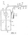
- Fig. 1 is a schematic view of one embodiment of a personal water and additive apparatus 10 according to the invention.
- Fig. 2 is partial perspective view of the embodiment of Fig. 1. In Fig. 2, the water container 12 is not shown.
- Fig. 3 is a sectional view of the manifold 20 of the embodiment of Fig. 1.
- apparatus 10 includes a first container 12 connected to a manifold 20 by a first tube 14.
- Container 12 is capable of holding liquid and includes a fill opening 36 and an outlet 34.
- container 12 is of the collapsible bladder type.
- Container 12 is filled with water 30.
- Second container 16 is connected to manifold 20 by a second tube 18.
- Container 16 is capable of holding liquid and preferably is a collapsible bladder type container.
- Container 16 is filled with additive 32 that will be mixed with water 30 from container 12.
- Second container 16 has a volume smaller than the first container 12, preferably less than half the volume of the first container 12.
- manifold 20 includes a water passageway 22 and an additive passageway 24.
- the water passageway 22 and additive passageway 24 intersect to form a single mixing passageway 46.
- the water passageway 22 has a larger diameter than the additive passageway 24.
- the relative sizes of the diameters of the water passageway 22 and additive passageway 24 are not critical because flow regulator 38, 40 controls the flow rate in passageways 22, 24 respectively and thereby create the desired proportions of water 30 and additive 32.
- the first tube 14 connects the first container 12 to the water passageway 22 of the manifold and the second tube 18 connects the second container 16 to the additive passageway 24.
- the combination of the first tube 14 and water passageway 22 define a water channel and the combination of the second tube 18 and the additive passageway 24 define an additive channel.
- An outlet tube 42 has one end connected to the mixing passageway 46 of the manifold. The other end of outlet tube 42 may optionally be connected to a bite valve 44.
- a check valve 26 is disposed in the water channel, preferably adjacent the manifold 20. Check valve 26 prevents reflux of water and/or water and additive mixture into the first tube 14 and the water 30 in container 12. Similarly, a check valve 28 is disposed in the additive channel, preferably adjacent the manifold 20, to prevent reflux into the additive container 16.
- adjustable flow regulator 3 8, 40 controls flow in the water passageway 22 and the additive passageway 24.
- adjustable flow regulator 38, 40 comprises a pair of independently operated threaded valves that can be rotated to fully open (full flow) or completely block (no flow) the water and additive passageways 22, 24.
- the adjustable flow regulator 38, 40 is infinitely adjustable between full flow and no flow.
- Another embodiment of a flow regulator (not shown) comprises a single spool valve or similar type valve to control flow through the two passageways 22, 24. In this embodiment, pushing in the valve would open the water passageway only, a further push would open both the water and additive passageways.
- Additive 32 in container 16 may be a liquid, solid or gel.
- An exemplary list of additives includes a beverage, a beverage concentrate, electrolytes, flavorings, carbohydrates, vitamins, aspirates, medications and dietary supplements.
- the additive container 16 is attached to the first tube 14 by a hook connector 48 extending from the base of container 16.
- Additive container 16 may be located further from manifold 20 by extending the tube 18.
- additive container 16 will not be reused. That is, a plurality of additive containers 16 containing different additives are available and can be connected to and disconnected from the apparatus 10, depending on the additive that is needed. When the additive 32 is depleted, or it is desired to use another additive, the additive container 16 is detached and another additive container is attached.
- the tube 18 is removably connected to the additive container 16. Such removable connections are known in the art and include, for example, barb connections, screw on connections (e.g., Leur lock, threaded) or connectors that use push-on type connections.
- the tube 18 is permanently connected to additive container 16 and removably connected to manifold 20. With the exception of water 30 and additive 32, all the components of apparatus 10 may be made of known plastic materials.
- an individual sucks on the optional bite valve 44 to draw water 30 and additive 32 into mixing passageway 46 and outlet tube 42.
- flow through either the water passageway 22 or additive passageway 24 is controlled by adjustable flow regulator 38, 40.
- adjustable flow regulator 38, 40 When both passageways 22, 24 are open, the act of sucking on the bite valve 44 simultaneously draws fluid from both containers 12, 16.
- additive 32 is a flavoring
- a flavored drink is automatically produced when the additive 32 and water 30 mix in the mixing passageway 46 of the manifold 20.
- the resulting drink mix travels through the outlet tube 42 and the bite valve 44.
- the concentration of additive 32 in the drink mix may be altered by adjusting flow regulator 38, 40.
- connectors used to fix tubes 14, 18 to manifold 20 are shown in the Figs. as barb connectors, however, other connectors may be used, such as connectors that screw on (e.g., Luer lock, threaded) or connectors that use push-on type connections.
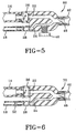
- Figs. 4-6 are sectional views of second, third and fourth embodiments of a manifold.
- Fig. 4 shows a manifold 50 that is different from manifold 20 in two ways. First, flow regulator 40 has been deleted and second, a restrictive orifice 52 has been added in the additive channel, preferably adjacent the manifold 50. Orifice 52 functions as a nonadjustable flow regulator for the additive channel. Different sized orifices 52 may be used, depending on the viscosity and the amount of additive desired to be mixed with water 30.
- Fig. 5 shows a manifold 60 that is identical to manifold 20 except that flow regulator 38 has been deleted.
- the proportion of additive 32 to water 30 is controlled by flow regulator 40 in the additive passageway 24.
- Fig. 6 shows a manifold 70 that is similar to manifold 50 of Fig. 4 except that flow regulator 38 has been deleted.
- Flow regulation in manifold 70 is accomplished by a restrictive orifice 52 in the additive channel, the orifice 52 preferably being located adjacent the manifold 70.
- the ratio of additive 32 to water 30 is dictated by the volumetric flow rate through each passageway 22, 24.
- the flow rates are dependent upon the fluid viscosity of the water 30 and additive 32 and the fluidic resistance of passageways 22, 24; tubes 14, 18; check valves 26, 28; and restrictive orifice 52.
- manifold 70 has the advantage of maintaining a fixed concentration of additive to water for a given assembly.
- the user may desire to change from a low viscosity additive (such as an electrolyte) to a higher viscosity additive (such as a carbohydrate) and mix the new additive with water at a different ratio.
- a different size restrictive orifice may be used in combination with the new additive to create the fluidic resistance necessary to obtain the desired concentration of the new additive to water.
Landscapes
- Chemical & Material Sciences (AREA)
- Chemical Kinetics & Catalysis (AREA)
- Devices For Dispensing Beverages (AREA)
Abstract
Description
- The invention relates in general to personal hydration devices and in particular to a personal hydration device that provides for the addition of substances into the personal water supply of an individual.
- Water is essential for good health. Individuals undergoing physical exertion, in particular soldiers, athletes and the physically active members of the public, have increased water consumption needs and thus often require a personal hydration device to maintain the necessary level of hydration. In addition, it can be advantageous to introduce other substances into the drinking water for purposes such as taste enhancement, electrolyte or essential salt replacement, nutritional support, etc.
- There may be several obstacles to sustaining hydration, electrolyte balance and energy status. For example, chlorinated or iodinated water commonly does not taste good thereby inhibiting water consumption. Attempting to improve electrolyte balance by simply adding sodium to chlorinated water, without flavoring, brings out the unpleasant taste of chlorine. The taste of water can be improved by adding flavorings, but flavorings almost instantly destroy residual chlorine and compromise resistance to contamination. The food intake of soldiers and other physically active people in the field is often inadequate. For example, soldiers in the field typically consume an inadequate amount of carbohydrate. However, simply adding carbohydrate to water increases the risk of mold and bacterial growth inside a personal bladder-type water reservoir. The bacterial contamination of water can cause diarrhea.
- Some known devices for personal hydration with additives require a separate drink container, for example, a canteen cup, to mix the drink ingredients. In other devices, the additive is added directly to the water reservoir, thereby contaminating the water reservoir and/or compromising water resistance to contamination.
-
DE-A-3101490 describes an apparatus for mixing a first liquid with a second liquid or a gas, for example for producing beverages. -
US-A-5593091 describes a system for mixing two or more interacting heated solutions for cleaning textiles. - The personal water and additive apparatus according to claim 1 comprises:
- a first container capable of holding liquid;
- a manifold having a water passageway and an additive passageway, the water passageway and additive passageway intersecting to form a single mixing passageway;
- a first tube connecting the first container to the water passageway of the manifold, the combination of the first tube and the water passageway defining a water channel;
- a second container capable of holding liquid;
- a second tube connecting the second container to the additive passageway of the manifold, the combination of the second tube and the additive passageway defining an additive channel; and
- an outlet tube having one end connected to the mixing passageway of the manifold; and is
- a check valve disposed in the water channel, and
- a flow regulator that controls flow in at least one of the water passageway and the additive passageway.
- In the present invention, a separate drink container is not required for mixing the additive with the water. In addition, the user is not required to physically add water to the additive or vice versa before consumption. Furthermore, the present invention does not contaminate the water reservoir or compromise water resistance to contamination.
- Typical personal bladder-type hydration systems such as
US-A-2003/0075573 comprise a water reservoir with a tube leading to a bite valve. The present invention improves on prior systems by allowing additives to be mixed with water just prior to being drawn through the bite valve into the user's mouth. Also, a check valve prevents contamination of the water in the reservoir. Thus, the invention provides additives to water in a manner that does not contaminate the water reservoir or compromise water resistance to contamination. - The invention enables the user to consume the nutrients or additives necessary for the chosen activity. The additives may include flavoring, macronutrients (i.e., carbohydrate, protein, fat), micronutrients (e.g., electrolytes, minerals, vitamins), aspirates, oral medications or other dietary supplements. In addition, the primary fluid may be something other than water, for example, a beverage.
- Further objects, features and advantages of the invention will become apparent from the following detailed description taken in conjunction with the following drawings.
- Throughout the Figures, reference numerals that are the same refer to the same features.
- Fig. 1 is a schematic view of one embodiment of the invention.
- Fig. 2 is a partial perspective view of the embodiment of Fig. 1.
- Fig. 3 is a sectional view of the manifold of the embodiment of Fig. 1.
- Fig. 4 is a sectional view of a second embodiment of a manifold.
- Fig. 5 is a sectional view of a third embodiment of a manifold.
- Fig. 6 is a sectional view of a fourth embodiment of a manifold.
- An important purpose of the invention is to introduce an additive into a personal water supply in such a way as to prevent contamination of the water reservoir by the additive. The invention enables the user to consume the additives necessary for their chosen activity while maintaining a reservoir supply of uncontaminated water. The composition of the additives is highly versatile and may include those specific to exercise such as electrolytes, flavoring, carbohydrates, vitamins, etc. Additionally, the device may be used to administer oral medications or dietary supplements. The additives may be in solid form, for example, granules or tablets, or in liquid or gel form.
- Fig. 1 is a schematic view of one embodiment of a personal water and
additive apparatus 10 according to the invention. Fig. 2 is partial perspective view of the embodiment of Fig. 1. In Fig. 2, thewater container 12 is not shown. Fig. 3 is a sectional view of themanifold 20 of the embodiment of Fig. 1. - Referring now to Figs. 1-3,
apparatus 10 includes afirst container 12 connected to amanifold 20 by afirst tube 14.Container 12 is capable of holding liquid and includes a fill opening 36 and anoutlet 34. Preferably,container 12 is of the collapsible bladder type.Container 12 is filled withwater 30.Second container 16 is connected tomanifold 20 by asecond tube 18.Container 16 is capable of holding liquid and preferably is a collapsible bladder type container.Container 16 is filled withadditive 32 that will be mixed withwater 30 fromcontainer 12.Second container 16 has a volume smaller than thefirst container 12, preferably less than half the volume of thefirst container 12. - As shown in detail in Fig. 3,
manifold 20 includes awater passageway 22 and anadditive passageway 24. Thewater passageway 22 andadditive passageway 24 intersect to form asingle mixing passageway 46. In some embodiments, thewater passageway 22 has a larger diameter than theadditive passageway 24. In the embodiment of Fig. 3, however, the relative sizes of the diameters of thewater passageway 22 andadditive passageway 24 are not critical becauseflow regulator passageways water 30 andadditive 32. Thefirst tube 14 connects thefirst container 12 to thewater passageway 22 of the manifold and thesecond tube 18 connects thesecond container 16 to theadditive passageway 24. The combination of thefirst tube 14 andwater passageway 22 define a water channel and the combination of thesecond tube 18 and theadditive passageway 24 define an additive channel. Anoutlet tube 42 has one end connected to the mixingpassageway 46 of the manifold. The other end ofoutlet tube 42 may optionally be connected to abite valve 44. - A
check valve 26 is disposed in the water channel, preferably adjacent themanifold 20. Checkvalve 26 prevents reflux of water and/or water and additive mixture into thefirst tube 14 and thewater 30 incontainer 12. Similarly, acheck valve 28 is disposed in the additive channel, preferably adjacent the manifold 20, to prevent reflux into theadditive container 16. - An adjustable flow regulator 3 8, 40 controls flow in the
water passageway 22 and theadditive passageway 24. In the embodiment of Fig. 3,adjustable flow regulator additive passageways adjustable flow regulator passageways Additive 32 incontainer 16 may be a liquid, solid or gel. An exemplary list of additives includes a beverage, a beverage concentrate, electrolytes, flavorings, carbohydrates, vitamins, aspirates, medications and dietary supplements. In the embodiment shown in Fig. 2, theadditive container 16 is attached to thefirst tube 14 by ahook connector 48 extending from the base ofcontainer 16.Additive container 16 may be located further frommanifold 20 by extending thetube 18. - It is contemplated that
additive container 16 will not be reused. That is, a plurality ofadditive containers 16 containing different additives are available and can be connected to and disconnected from theapparatus 10, depending on the additive that is needed. When the additive 32 is depleted, or it is desired to use another additive, theadditive container 16 is detached and another additive container is attached. In one embodiment, thetube 18 is removably connected to theadditive container 16. Such removable connections are known in the art and include, for example, barb connections, screw on connections (e.g., Leur lock, threaded) or connectors that use push-on type connections. In another embodiment, thetube 18 is permanently connected toadditive container 16 and removably connected tomanifold 20. With the exception ofwater 30 andadditive 32, all the components ofapparatus 10 may be made of known plastic materials. - To use
apparatus 10, an individual sucks on theoptional bite valve 44 to drawwater 30 and additive 32 into mixingpassageway 46 andoutlet tube 42. In the embodiment of Figs. 1-3, flow through either thewater passageway 22 oradditive passageway 24 is controlled byadjustable flow regulator passageways bite valve 44 simultaneously draws fluid from bothcontainers additive 32 is a flavoring, then a flavored drink is automatically produced when the additive 32 andwater 30 mix in the mixingpassageway 46 of the manifold 20. The resulting drink mix travels through theoutlet tube 42 and thebite valve 44. The concentration ofadditive 32 in the drink mix may be altered by adjustingflow regulator - The connectors used to fix
tubes manifold 20 are shown in the Figs. as barb connectors, however, other connectors may be used, such as connectors that screw on (e.g., Luer lock, threaded) or connectors that use push-on type connections. - Figs. 4-6 are sectional views of second, third and fourth embodiments of a manifold. Fig. 4 shows a manifold 50 that is different from manifold 20 in two ways. First, flow
regulator 40 has been deleted and second, arestrictive orifice 52 has been added in the additive channel, preferably adjacent themanifold 50.Orifice 52 functions as a nonadjustable flow regulator for the additive channel. Differentsized orifices 52 may be used, depending on the viscosity and the amount of additive desired to be mixed withwater 30. - Fig. 5 shows a manifold 60 that is identical to manifold 20 except that
flow regulator 38 has been deleted. The proportion ofadditive 32 towater 30 is controlled byflow regulator 40 in theadditive passageway 24. Fig. 6 shows a manifold 70 that is similar tomanifold 50 of Fig. 4 except thatflow regulator 38 has been deleted. Flow regulation inmanifold 70 is accomplished by arestrictive orifice 52 in the additive channel, theorifice 52 preferably being located adjacent themanifold 70. - In the embodiment of Fig. 6, the ratio of
additive 32 towater 30 is dictated by the volumetric flow rate through eachpassageway water 30 andadditive 32 and the fluidic resistance ofpassageways tubes check valves restrictive orifice 52. Because the flow rates inmanifold 70 are fixed for a givenadditive 32,manifold 70 has the advantage of maintaining a fixed concentration of additive to water for a given assembly. On the other hand, it is contemplated that the user may desire to change from a low viscosity additive (such as an electrolyte) to a higher viscosity additive (such as a carbohydrate) and mix the new additive with water at a different ratio. In such a case, a different size restrictive orifice may be used in combination with the new additive to create the fluidic resistance necessary to obtain the desired concentration of the new additive to water.
Claims (22)
- A personal water and additive apparatus (10), comprising:a first container (12) capable of holding liquid (30);a manifold (20) having a water passageway (22) and an additive passageway (24), the water passageway and additive passageway intersecting to form a single mixing passageway (46);a first tube (14) connecting the first container to the water passageway of the manifold, the combination of the first tube and the water passageway defining a water channel;a second container (16) capable of holding liquid (32);a second tube (18) connecting the second container to the additive passageway of the manifold, the combination of the second tube and the additive passageway defining an additive channel; andan outlet tube (42) having one end connected to the mixing passageway of the manifold;characterized in that the apparatus further comprises:a check valve (26) disposed in the water channel, anda flow regulator (38, 40, 52) that controls flow in at least one of the water passageway and the additive passageway.
- The apparatus of claim 1 wherein the flow regulator is an adjustable flow regulator (38, 40).
- The apparatus of claim 2 wherein the adjustable flow regulator (38) controls flow in only the water passageway.
- The apparatus of claim 2 wherein the adjustable flow regulator (40) controls flow in only the additive passageway.
- The apparatus of claim 2 wherein the adjustable flow regulator (38, 40) controls flow in both the water passageway and the additive passageway.
- The apparatus of claim 2 wherein the adjustable flow regulator (38, 40) is adjustable to allow full flow or to allow no flow.
- The apparatus of claim 6 wherein the adjustable flow regulator (38, 40) is infinitely adjustable between full flow and no flow.
- The apparatus of claim 1 wherein the first container comprises a collapsible bladder (12).
- The apparatus of claim 1 wherein the second container comprises a collapsible bladder (16).
- The apparatus of claim 1 further comprising one of water and a beverage in the first container.
- The apparatus of claim 1 wherein the water passageway (22) has a larger diameter than the additive passageway (24).
- The apparatus of claim 1 further comprising an additive (32) disposed in the second container, the additive comprising at least one of a liquid, solid and gel.
- The apparatus of claim 12 wherein the additive comprises at least one of a beverage, a beverage concentrate, flavoring, macronutrients, micronutrients, oral medications, aspirates, and dietary supplements.
- The apparatus of claim 1 wherein the flow regulator (38, 40, 52) comprises a restrictive orifice disposed in the additive channel.
- The apparatus of claim 1 further comprising a second check valve (28) disposed in the additive channel.
- The apparatus of claim 1 further comprising a bite valve (44) attached to another end of the outlet tube (42).
- The apparatus of claim 1 wherein the second container (16) has a volume smaller than the first container (12).
- The apparatus of claim 17 wherein the first container (12) comprises a collapsible bladder.
- The apparatus of claim 17 wherein the second container (16) comprises a collapsible bladder.
- The apparatus of claim 17 further comprising an additive (32) disposed in the second container, the additive comprising at least one of a liquid, solid and gel.
- The apparatus of claim 20 wherein the additive (32) comprises at least one of a beverage, a beverage concentrate, flavoring, macronutrients, micronutrients, oral medications, aspirates, and dietary supplements.
- The apparatus of claim 17 further comprising a second check valve (28) disposed in the additive channel.
Applications Claiming Priority (2)
| Application Number | Priority Date | Filing Date | Title |
|---|---|---|---|
| US48346503P | 2003-06-30 | 2003-06-30 | |
| PCT/US2004/020110 WO2005005030A1 (en) | 2003-06-30 | 2004-06-23 | Drinking container, including a mixing device for the introduction of additives |
Publications (2)
| Publication Number | Publication Date |
|---|---|
| EP1644108A1 EP1644108A1 (en) | 2006-04-12 |
| EP1644108B1 true EP1644108B1 (en) | 2007-12-19 |
Family
ID=34061959
Family Applications (1)
| Application Number | Title | Priority Date | Filing Date |
|---|---|---|---|
| EP04755939A Expired - Lifetime EP1644108B1 (en) | 2003-06-30 | 2004-06-23 | Personal hydration reservoir, including a mixing device for the introduction of additives |
Country Status (7)
| Country | Link |
|---|---|
| US (2) | US7533786B2 (en) |
| EP (1) | EP1644108B1 (en) |
| AT (1) | ATE381383T1 (en) |
| CA (1) | CA2529291C (en) |
| DE (1) | DE602004010811D1 (en) |
| ES (1) | ES2298786T3 (en) |
| WO (1) | WO2005005030A1 (en) |
Families Citing this family (47)
| Publication number | Priority date | Publication date | Assignee | Title |
|---|---|---|---|---|
| CA2606995A1 (en) * | 2005-04-29 | 2006-11-09 | Ipifini, Inc. | Programmable liquid containers |
| US7487888B1 (en) * | 2005-07-15 | 2009-02-10 | Pierre Jr Lloyd A | Fluid dispensing apparatus |
| US20070090135A1 (en) * | 2005-10-25 | 2007-04-26 | Benham Christopher J | Single and dual disposable hydration system |
| US7891524B1 (en) * | 2006-05-26 | 2011-02-22 | Precise Mix, LLC | Fuel and oil mixing device |
| TWM304496U (en) * | 2006-06-02 | 2007-01-11 | Lo-Pin Wang | Structure of water supplying head for water bag |
| US20080142548A1 (en) * | 2006-12-13 | 2008-06-19 | Frozen Beverage Services Of California, Inc. | Method and Apparatus for Combination and Delivery of Beverages for Consumption |
| DE102007022205A1 (en) * | 2007-05-11 | 2008-11-13 | Kaltenbach & Voigt Gmbh | Hand-held device for dispensing a pasty filling material |
| WO2009023849A1 (en) * | 2007-08-16 | 2009-02-19 | The Coleman Company, Inc. | Multiple chamber hydration pack |
| FR2921807B1 (en) * | 2007-10-05 | 2011-04-22 | Fabien Andrieux | PROCESS FOR THE PREPARATION OF A WATER-BASED BEVERAGE AND A LIQUID ADDITIVE AND KIT FOR PREPARING SUCH BEVERAGE |
| US20100107564A1 (en) * | 2008-09-09 | 2010-05-06 | Macler Jr Henry J | Patched Drinking Water Bag |
| US8167174B2 (en) * | 2008-09-17 | 2012-05-01 | Harvey Elliott Berger | Inline fluid dispenser |
| US8544688B2 (en) * | 2009-02-20 | 2013-10-01 | Simple Matter, Inc. | Personal hydration system with control valve assembly |
| US8622249B1 (en) * | 2009-02-20 | 2014-01-07 | Simple Matter, Inc. | Personal hydration system with control valve assembly |
| EP2403775A4 (en) * | 2009-03-03 | 2012-08-01 | Gidi Shani | Volume adjusted preservation containment system |
| US8201711B2 (en) * | 2010-01-06 | 2012-06-19 | Chien-Ping Lien | Mixing device for individual hydration unit |
| WO2011115618A1 (en) * | 2010-03-16 | 2011-09-22 | Harvey Elliott Berger | Inline fluid dispenser |
| US8408425B2 (en) * | 2010-09-07 | 2013-04-02 | Chien-Ping Lien | Hydration device |
| BR112013028171A2 (en) * | 2011-05-02 | 2020-05-12 | Mouse Trap Design, Llc | DEVICE FOR MIXING A FLUID PLURALITY TO FORMULATE A MIXTURE AND TO DISPENSE THE MIXTURE |
| US9017749B2 (en) | 2011-12-21 | 2015-04-28 | Babatope Sewande Ayeni | Flavored straw with a flavor delivery system |
| US9149109B2 (en) * | 2012-01-09 | 2015-10-06 | Rocket44 LLC | Two reservoir fluid delivery system |
| US20130277449A1 (en) * | 2012-04-18 | 2013-10-24 | Tal Alon | Enhanced drinking straws |
| US10053356B2 (en) | 2012-04-24 | 2018-08-21 | Rx Hydration, Inc. | Systems, kits and methods for hands free, on demand, oral delivery of materials |
| US9499390B1 (en) * | 2012-07-17 | 2016-11-22 | Global Agricultural Technology And Engineering, Llc | Liquid delivery system |
| US9795242B2 (en) | 2013-02-14 | 2017-10-24 | Cirkul, Inc. | Additive delivery systems and containers |
| US9114368B2 (en) | 2013-03-08 | 2015-08-25 | Cornelius, Inc. | Batch carbonator and method of forming a carbonated beverage |
| US20150053718A1 (en) * | 2013-08-26 | 2015-02-26 | Hydrapak, Inc. | Reservoir system and method of making |
| US9210990B2 (en) * | 2013-09-16 | 2015-12-15 | Matt Hoskins | Multi-chamber fluid containers |
| US20150122837A1 (en) | 2013-11-07 | 2015-05-07 | Mouse Trap Design, Llc | Mixing and dispensing device |
| US9615649B2 (en) * | 2014-06-30 | 2017-04-11 | Raymond Bradley Melling | Hydration dispensing device |
| US10888826B2 (en) | 2014-11-21 | 2021-01-12 | Cirkul, Inc. | Adjustable additive cartridge systems and methods |
| CN107205565B (en) | 2014-11-21 | 2020-07-03 | 塞考尔有限公司 | Adjustable additive cartridge system |
| GB2539028A (en) * | 2015-06-04 | 2016-12-07 | Steven Davidson Andrew | Device for water supplementation |
| US10785996B2 (en) | 2015-08-25 | 2020-09-29 | Cornelius, Inc. | Apparatuses, systems, and methods for inline injection of gases into liquids |
| US10477883B2 (en) | 2015-08-25 | 2019-11-19 | Cornelius, Inc. | Gas injection assemblies for batch beverages having spargers |
| USD784085S1 (en) * | 2016-02-03 | 2017-04-18 | Dianna Langston | Water bottle with extended straw |
| EP3422911A4 (en) * | 2016-03-04 | 2019-08-07 | Cirkul, Inc. | SYSTEMS AND METHODS FOR ADMINABLE ADDITIVE DELIVERY |
| US10502351B2 (en) | 2016-07-18 | 2019-12-10 | Rainmaker Solutions, Inc. | Wireless actuation system for hydration system |
| CN106165964B (en) * | 2016-08-23 | 2018-03-30 | 西藏珠峰冰川水资源开发有限公司 | A kind of drinking device |
| US10492552B2 (en) | 2016-11-17 | 2019-12-03 | Rainmaker Solutions, Inc. | Hydration and audio system |
| US12017191B2 (en) | 2017-03-06 | 2024-06-25 | Cirkul, Inc. | Adjustable additive delivery systems and dispensing closure valves for the same |
| US20190031484A1 (en) * | 2017-07-31 | 2019-01-31 | Timothy J. Allgood | Beer tap improvement system for colored beer and other additives |
| WO2019147715A1 (en) | 2018-01-23 | 2019-08-01 | Infuze, Llc | Water bottle device assembly |
| US11040314B2 (en) | 2019-01-08 | 2021-06-22 | Marmon Foodservice Technologies, Inc. | Apparatuses, systems, and methods for injecting gasses into beverages |
| EP3825252A1 (en) * | 2019-11-20 | 2021-05-26 | Hilti Aktiengesellschaft | Cartridge and top part for a cartridge |
| US11185148B2 (en) * | 2020-03-06 | 2021-11-30 | Custom Club, Inc. | Oral device container and oral device container and bottle assembly |
| US11905097B2 (en) | 2020-07-10 | 2024-02-20 | o6 Innovations Inc. | Multi-compartment beverage container for dispensing a mixed beverage |
| US20220288541A1 (en) * | 2021-03-12 | 2022-09-15 | Drop Water Corporation | Multi additive channel head |
Family Cites Families (29)
| Publication number | Priority date | Publication date | Assignee | Title |
|---|---|---|---|---|
| US1707058A (en) * | 1929-03-26 | Hermann kauwebtz | ||
| US3348737A (en) * | 1966-05-18 | 1967-10-24 | Universal Match Corp | Dispensers |
| US3411534A (en) * | 1966-12-28 | 1968-11-19 | Tracor | Four-way valve |
| US3463361A (en) | 1968-01-26 | 1969-08-26 | Wham O Mfg Co | Flavoring device |
| US3785616A (en) | 1971-07-15 | 1974-01-15 | Moore Prod Co | Metering valve |
| US3976068A (en) | 1975-01-03 | 1976-08-24 | Origo, Inc. | Drug dispenser for use with intravenous feeding pump |
| US4042684A (en) | 1976-03-23 | 1977-08-16 | Annika Britt Kahm | Dietetic beverage |
| US4279362A (en) | 1979-01-26 | 1981-07-21 | Pursell Grant W | Dispensing of hygienic fluids |
| AU534984B2 (en) * | 1979-09-19 | 1984-02-23 | Baxter International Inc. | Nutrient solution mixing |
| DE3101490A1 (en) * | 1981-01-19 | 1982-08-26 | Füllpack Dipl.Brauerei-Ing. Dieter Wieland, 4000 Düsseldorf | Apparatus for mixing a first liquid with a second liquid or a gas, in particular for the production of beverages |
| GB2116058B (en) * | 1982-02-02 | 1986-06-18 | Booth Dispensers | Mixing drinks |
| US4692144A (en) | 1984-08-20 | 1987-09-08 | Alza Corporation | System for providing intravenously administrable drug formulation |
| AP39A (en) | 1986-01-08 | 1989-04-20 | Stephen Roskilly | Improvements ralating to baby feeding bottles. |
| US4681244A (en) * | 1986-04-30 | 1987-07-21 | Geddie John D | Portable bar |
| US4815635A (en) | 1987-11-16 | 1989-03-28 | Porter Willie E | Cyclist water supply apparatus |
| US5032411A (en) | 1990-02-27 | 1991-07-16 | University Of Texas System Board Of Regents | Beverage compositions for human consumption |
| GB2249775A (en) * | 1990-11-13 | 1992-05-20 | Gordon Ronald Tripp | Flexible liquid container |
| US5188090A (en) * | 1991-04-08 | 1993-02-23 | Hydro Dynamics, Inc. | Apparatus for heating fluids |
| US5249702A (en) | 1992-01-24 | 1993-10-05 | Topp Kathy R | Beverage container and support bracket therefore |
| US5188019A (en) * | 1992-03-30 | 1993-02-23 | Vahabpour Abdolvahab K | Automatic tea maker |
| US5593091A (en) * | 1994-11-07 | 1997-01-14 | Harris Research, Inc. | Dual solution application system |
| DE29606710U1 (en) * | 1996-04-12 | 1996-06-27 | Hilger u. Kern GmbH, 68167 Mannheim | Device for dosing and mixing at least two liquid to pasty media |
| US6032873A (en) * | 1998-10-26 | 2000-03-07 | Weinstein; Robert E. | Liquid drinking assemblage |
| US6216961B1 (en) | 1999-05-12 | 2001-04-17 | Misty Mate Inc | Fan propelled mister |
| WO2002016227A1 (en) * | 2000-08-25 | 2002-02-28 | Wella Aktiengesellschaft | Device with a mixing chamber |
| US6503222B2 (en) | 2000-09-28 | 2003-01-07 | Pfizer Inc | Oral dosage dispenser |
| US6749090B2 (en) * | 2001-10-22 | 2004-06-15 | Trek Bicycle Corporation | Dual bladder sports hydration system |
| AU2003253978A1 (en) | 2002-07-19 | 2004-02-09 | William L. Courtney | Mixed-fluid delivery system for body armor pfd, boater or cyclist |
| US6837026B2 (en) | 2002-09-20 | 2005-01-04 | David Setton | Pre-filled personal hydration reservoir |
-
2004
- 2004-06-23 WO PCT/US2004/020110 patent/WO2005005030A1/en not_active Ceased
- 2004-06-23 DE DE602004010811T patent/DE602004010811D1/en not_active Expired - Lifetime
- 2004-06-23 US US10/875,020 patent/US7533786B2/en not_active Expired - Fee Related
- 2004-06-23 EP EP04755939A patent/EP1644108B1/en not_active Expired - Lifetime
- 2004-06-23 ES ES04755939T patent/ES2298786T3/en not_active Expired - Lifetime
- 2004-06-23 AT AT04755939T patent/ATE381383T1/en not_active IP Right Cessation
- 2004-06-23 CA CA002529291A patent/CA2529291C/en not_active Expired - Fee Related
-
2009
- 2009-02-20 US US12/389,701 patent/US7658303B2/en not_active Expired - Fee Related
Also Published As
| Publication number | Publication date |
|---|---|
| CA2529291A1 (en) | 2005-01-20 |
| US7658303B2 (en) | 2010-02-09 |
| EP1644108A1 (en) | 2006-04-12 |
| DE602004010811D1 (en) | 2008-01-31 |
| US7533786B2 (en) | 2009-05-19 |
| US20090152298A1 (en) | 2009-06-18 |
| ATE381383T1 (en) | 2008-01-15 |
| WO2005005030A1 (en) | 2005-01-20 |
| US20040262331A1 (en) | 2004-12-30 |
| CA2529291C (en) | 2009-05-19 |
| ES2298786T3 (en) | 2008-05-16 |
Similar Documents
| Publication | Publication Date | Title |
|---|---|---|
| CA2529291C (en) | Drinking container, including a mixing device for the introduction of additives | |
| US20230406686A1 (en) | On demand functional beverage dispenser | |
| US12168207B2 (en) | Water bottle device assembly | |
| US8158084B2 (en) | Control scheme for enhanced filtered water systems | |
| US9656849B2 (en) | Modular valve array having a single dispense point | |
| JP2021534967A (en) | Beverage dispenser head for mixing concentrates, diluents and additives | |
| JP2019513534A (en) | System and method for making a nitrogen-infused beverage | |
| WO2011133779A2 (en) | Liquid decanting method and apparatus | |
| US10052593B2 (en) | Liquid aerating device | |
| US5957339A (en) | Water filtration system | |
| CN112041258A (en) | Preparation of independent beverage streams | |
| JP2008513105A (en) | Bypass line connector for mixing systems | |
| US20240116014A1 (en) | Liquid dispensing apparatus for controllable mixing of liquids | |
| CN112055540A (en) | Gas Liquid Absorption Device (GLAD) with Replaceable Gas Orifice Fittings and Sensors | |
| KR100638799B1 (en) | Oxygen dissolving device and supersaturated oxygen water production device using same | |
| DE3470465D1 (en) | Apparatus for mixing milk with flavouring and fluoride | |
| CN201547325U (en) | a mixing valve | |
| US20260042654A1 (en) | Systems and methods for carbonating and dispensing a beverage | |
| TWM598098U (en) | Flavoring straw | |
| US20030001022A1 (en) | Liquid control cup | |
| CN220776963U (en) | Animal feeding device | |
| CN115349764A (en) | a method of bartending | |
| CN210055687U (en) | Beverage mixer | |
| CN201362388Y (en) | Bottle with inner part divided into a plurality of spaces | |
| JPS6193098A (en) | Supply circuit for calcareous water to drink dispenser |
Legal Events
| Date | Code | Title | Description |
|---|---|---|---|
| PUAI | Public reference made under article 153(3) epc to a published international application that has entered the european phase |
Free format text: ORIGINAL CODE: 0009012 |
|
| 17P | Request for examination filed |
Effective date: 20060105 |
|
| AK | Designated contracting states |
Kind code of ref document: A1 Designated state(s): AT BE BG CH CY CZ DE DK EE ES FI FR GB GR HU IE IT LI LU MC NL PL PT RO SE SI SK TR |
|
| AX | Request for extension of the european patent |
Extension state: AL HR LT LV MK |
|
| GRAP | Despatch of communication of intention to grant a patent |
Free format text: ORIGINAL CODE: EPIDOSNIGR1 |
|
| RTI1 | Title (correction) |
Free format text: PERSONAL HYDRATION RESERVOIR, INCLUDING A MIXING DEVICE FOR THE INTRODUCTION OF ADDITIVES |
|
| GRAS | Grant fee paid |
Free format text: ORIGINAL CODE: EPIDOSNIGR3 |
|
| GRAA | (expected) grant |
Free format text: ORIGINAL CODE: 0009210 |
|
| AK | Designated contracting states |
Kind code of ref document: B1 Designated state(s): AT BE BG CH CY CZ DE DK EE ES FI FR GB GR HU IE IT LI LU MC NL PL PT RO SE SI SK TR |
|
| AX | Request for extension of the european patent |
Extension state: AL HR LT LV MK |
|
| REG | Reference to a national code |
Ref country code: GB Ref legal event code: FG4D |
|
| REG | Reference to a national code |
Ref country code: IE Ref legal event code: FG4D |
|
| REG | Reference to a national code |
Ref country code: CH Ref legal event code: EP |
|
| REF | Corresponds to: |
Ref document number: 602004010811 Country of ref document: DE Date of ref document: 20080131 Kind code of ref document: P |
|
| PG25 | Lapsed in a contracting state [announced via postgrant information from national office to epo] |
Ref country code: CH Free format text: LAPSE BECAUSE OF FAILURE TO SUBMIT A TRANSLATION OF THE DESCRIPTION OR TO PAY THE FEE WITHIN THE PRESCRIBED TIME-LIMIT Effective date: 20071219 Ref country code: SE Free format text: LAPSE BECAUSE OF FAILURE TO SUBMIT A TRANSLATION OF THE DESCRIPTION OR TO PAY THE FEE WITHIN THE PRESCRIBED TIME-LIMIT Effective date: 20080319 Ref country code: LI Free format text: LAPSE BECAUSE OF FAILURE TO SUBMIT A TRANSLATION OF THE DESCRIPTION OR TO PAY THE FEE WITHIN THE PRESCRIBED TIME-LIMIT Effective date: 20071219 |
|
| REG | Reference to a national code |
Ref country code: ES Ref legal event code: FG2A Ref document number: 2298786 Country of ref document: ES Kind code of ref document: T3 |
|
| LTIE | Lt: invalidation of european patent or patent extension |
Effective date: 20071219 |
|
| PG25 | Lapsed in a contracting state [announced via postgrant information from national office to epo] |
Ref country code: NL Free format text: LAPSE BECAUSE OF FAILURE TO SUBMIT A TRANSLATION OF THE DESCRIPTION OR TO PAY THE FEE WITHIN THE PRESCRIBED TIME-LIMIT Effective date: 20071219 Ref country code: PL Free format text: LAPSE BECAUSE OF FAILURE TO SUBMIT A TRANSLATION OF THE DESCRIPTION OR TO PAY THE FEE WITHIN THE PRESCRIBED TIME-LIMIT Effective date: 20071219 Ref country code: SI Free format text: LAPSE BECAUSE OF FAILURE TO SUBMIT A TRANSLATION OF THE DESCRIPTION OR TO PAY THE FEE WITHIN THE PRESCRIBED TIME-LIMIT Effective date: 20071219 Ref country code: FI Free format text: LAPSE BECAUSE OF FAILURE TO SUBMIT A TRANSLATION OF THE DESCRIPTION OR TO PAY THE FEE WITHIN THE PRESCRIBED TIME-LIMIT Effective date: 20071219 |
|
| NLV1 | Nl: lapsed or annulled due to failure to fulfill the requirements of art. 29p and 29m of the patents act | ||
| REG | Reference to a national code |
Ref country code: CH Ref legal event code: PL |
|
| PG25 | Lapsed in a contracting state [announced via postgrant information from national office to epo] |
Ref country code: AT Free format text: LAPSE BECAUSE OF FAILURE TO SUBMIT A TRANSLATION OF THE DESCRIPTION OR TO PAY THE FEE WITHIN THE PRESCRIBED TIME-LIMIT Effective date: 20071219 |
|
| PG25 | Lapsed in a contracting state [announced via postgrant information from national office to epo] |
Ref country code: CZ Free format text: LAPSE BECAUSE OF FAILURE TO SUBMIT A TRANSLATION OF THE DESCRIPTION OR TO PAY THE FEE WITHIN THE PRESCRIBED TIME-LIMIT Effective date: 20071219 |
|
| ET | Fr: translation filed | ||
| PG25 | Lapsed in a contracting state [announced via postgrant information from national office to epo] |
Ref country code: SK Free format text: LAPSE BECAUSE OF FAILURE TO SUBMIT A TRANSLATION OF THE DESCRIPTION OR TO PAY THE FEE WITHIN THE PRESCRIBED TIME-LIMIT Effective date: 20071219 Ref country code: RO Free format text: LAPSE BECAUSE OF FAILURE TO SUBMIT A TRANSLATION OF THE DESCRIPTION OR TO PAY THE FEE WITHIN THE PRESCRIBED TIME-LIMIT Effective date: 20071219 Ref country code: BE Free format text: LAPSE BECAUSE OF FAILURE TO SUBMIT A TRANSLATION OF THE DESCRIPTION OR TO PAY THE FEE WITHIN THE PRESCRIBED TIME-LIMIT Effective date: 20071219 |
|
| PG25 | Lapsed in a contracting state [announced via postgrant information from national office to epo] |
Ref country code: PT Free format text: LAPSE BECAUSE OF FAILURE TO SUBMIT A TRANSLATION OF THE DESCRIPTION OR TO PAY THE FEE WITHIN THE PRESCRIBED TIME-LIMIT Effective date: 20080519 |
|
| PLBE | No opposition filed within time limit |
Free format text: ORIGINAL CODE: 0009261 |
|
| STAA | Information on the status of an ep patent application or granted ep patent |
Free format text: STATUS: NO OPPOSITION FILED WITHIN TIME LIMIT |
|
| PG25 | Lapsed in a contracting state [announced via postgrant information from national office to epo] |
Ref country code: DK Free format text: LAPSE BECAUSE OF FAILURE TO SUBMIT A TRANSLATION OF THE DESCRIPTION OR TO PAY THE FEE WITHIN THE PRESCRIBED TIME-LIMIT Effective date: 20071219 Ref country code: DE Free format text: LAPSE BECAUSE OF FAILURE TO SUBMIT A TRANSLATION OF THE DESCRIPTION OR TO PAY THE FEE WITHIN THE PRESCRIBED TIME-LIMIT Effective date: 20080320 |
|
| 26N | No opposition filed |
Effective date: 20080922 |
|
| PG25 | Lapsed in a contracting state [announced via postgrant information from national office to epo] |
Ref country code: MC Free format text: LAPSE BECAUSE OF NON-PAYMENT OF DUE FEES Effective date: 20080630 Ref country code: GR Free format text: LAPSE BECAUSE OF FAILURE TO SUBMIT A TRANSLATION OF THE DESCRIPTION OR TO PAY THE FEE WITHIN THE PRESCRIBED TIME-LIMIT Effective date: 20080320 |
|
| PG25 | Lapsed in a contracting state [announced via postgrant information from national office to epo] |
Ref country code: BG Free format text: LAPSE BECAUSE OF FAILURE TO SUBMIT A TRANSLATION OF THE DESCRIPTION OR TO PAY THE FEE WITHIN THE PRESCRIBED TIME-LIMIT Effective date: 20080319 Ref country code: EE Free format text: LAPSE BECAUSE OF FAILURE TO SUBMIT A TRANSLATION OF THE DESCRIPTION OR TO PAY THE FEE WITHIN THE PRESCRIBED TIME-LIMIT Effective date: 20071219 |
|
| PG25 | Lapsed in a contracting state [announced via postgrant information from national office to epo] |
Ref country code: CY Free format text: LAPSE BECAUSE OF FAILURE TO SUBMIT A TRANSLATION OF THE DESCRIPTION OR TO PAY THE FEE WITHIN THE PRESCRIBED TIME-LIMIT Effective date: 20071219 |
|
| PG25 | Lapsed in a contracting state [announced via postgrant information from national office to epo] |
Ref country code: LU Free format text: LAPSE BECAUSE OF NON-PAYMENT OF DUE FEES Effective date: 20080623 Ref country code: HU Free format text: LAPSE BECAUSE OF FAILURE TO SUBMIT A TRANSLATION OF THE DESCRIPTION OR TO PAY THE FEE WITHIN THE PRESCRIBED TIME-LIMIT Effective date: 20080620 |
|
| PG25 | Lapsed in a contracting state [announced via postgrant information from national office to epo] |
Ref country code: TR Free format text: LAPSE BECAUSE OF FAILURE TO SUBMIT A TRANSLATION OF THE DESCRIPTION OR TO PAY THE FEE WITHIN THE PRESCRIBED TIME-LIMIT Effective date: 20071219 |
|
| REG | Reference to a national code |
Ref country code: FR Ref legal event code: PLFP Year of fee payment: 13 |
|
| REG | Reference to a national code |
Ref country code: FR Ref legal event code: PLFP Year of fee payment: 14 |
|
| PGFP | Annual fee paid to national office [announced via postgrant information from national office to epo] |
Ref country code: IE Payment date: 20170622 Year of fee payment: 14 Ref country code: FR Payment date: 20170511 Year of fee payment: 14 Ref country code: GB Payment date: 20170621 Year of fee payment: 14 |
|
| PGFP | Annual fee paid to national office [announced via postgrant information from national office to epo] |
Ref country code: IT Payment date: 20170619 Year of fee payment: 14 |
|
| PGFP | Annual fee paid to national office [announced via postgrant information from national office to epo] |
Ref country code: ES Payment date: 20170704 Year of fee payment: 14 |
|
| GBPC | Gb: european patent ceased through non-payment of renewal fee |
Effective date: 20180623 |
|
| REG | Reference to a national code |
Ref country code: IE Ref legal event code: MM4A |
|
| PG25 | Lapsed in a contracting state [announced via postgrant information from national office to epo] |
Ref country code: IE Free format text: LAPSE BECAUSE OF NON-PAYMENT OF DUE FEES Effective date: 20180623 Ref country code: GB Free format text: LAPSE BECAUSE OF NON-PAYMENT OF DUE FEES Effective date: 20180623 Ref country code: FR Free format text: LAPSE BECAUSE OF NON-PAYMENT OF DUE FEES Effective date: 20180630 Ref country code: IT Free format text: LAPSE BECAUSE OF NON-PAYMENT OF DUE FEES Effective date: 20180623 |
|
| REG | Reference to a national code |
Ref country code: ES Ref legal event code: FD2A Effective date: 20190916 |
|
| PG25 | Lapsed in a contracting state [announced via postgrant information from national office to epo] |
Ref country code: ES Free format text: LAPSE BECAUSE OF NON-PAYMENT OF DUE FEES Effective date: 20180624 |