EP1643732A2 - Mobile communication terminal - Google Patents
Mobile communication terminal Download PDFInfo
- Publication number
- EP1643732A2 EP1643732A2 EP05021638A EP05021638A EP1643732A2 EP 1643732 A2 EP1643732 A2 EP 1643732A2 EP 05021638 A EP05021638 A EP 05021638A EP 05021638 A EP05021638 A EP 05021638A EP 1643732 A2 EP1643732 A2 EP 1643732A2
- Authority
- EP
- European Patent Office
- Prior art keywords
- mobile communication
- communication terminal
- hinge
- housing
- key
- Prior art date
- Legal status (The legal status is an assumption and is not a legal conclusion. Google has not performed a legal analysis and makes no representation as to the accuracy of the status listed.)
- Granted
Links
Images


Classifications
-
- H—ELECTRICITY
- H04—ELECTRIC COMMUNICATION TECHNIQUE
- H04M—TELEPHONIC COMMUNICATION
- H04M1/00—Substation equipment, e.g. for use by subscribers
- H04M1/02—Constructional features of telephone sets
- H04M1/0202—Portable telephone sets, e.g. cordless phones, mobile phones or bar type handsets
- H04M1/0206—Portable telephones comprising a plurality of mechanically joined movable body parts, e.g. hinged housings
- H04M1/0208—Portable telephones comprising a plurality of mechanically joined movable body parts, e.g. hinged housings characterized by the relative motions of the body parts
- H04M1/0214—Foldable telephones, i.e. with body parts pivoting to an open position around an axis parallel to the plane they define in closed position
- H04M1/0216—Foldable in one direction, i.e. using a one degree of freedom hinge
- H04M1/0218—The hinge comprising input and/or output user interface means
-
- H—ELECTRICITY
- H04—ELECTRIC COMMUNICATION TECHNIQUE
- H04B—TRANSMISSION
- H04B1/00—Details of transmission systems, not covered by a single one of groups H04B3/00 - H04B13/00; Details of transmission systems not characterised by the medium used for transmission
- H04B1/38—Transceivers, i.e. devices in which transmitter and receiver form a structural unit and in which at least one part is used for functions of transmitting and receiving
-
- H—ELECTRICITY
- H04—ELECTRIC COMMUNICATION TECHNIQUE
- H04M—TELEPHONIC COMMUNICATION
- H04M1/00—Substation equipment, e.g. for use by subscribers
- H04M1/02—Constructional features of telephone sets
- H04M1/03—Constructional features of telephone transmitters or receivers, e.g. telephone hand-sets
-
- H—ELECTRICITY
- H04—ELECTRIC COMMUNICATION TECHNIQUE
- H04M—TELEPHONIC COMMUNICATION
- H04M1/00—Substation equipment, e.g. for use by subscribers
- H04M1/02—Constructional features of telephone sets
- H04M1/23—Construction or mounting of dials or of equivalent devices; Means for facilitating the use thereof
- H04M1/233—Construction or mounting of dials or of equivalent devices; Means for facilitating the use thereof including a pointing device, e.g. roller key, track ball, rocker switch or joystick
-
- H—ELECTRICITY
- H04—ELECTRIC COMMUNICATION TECHNIQUE
- H04M—TELEPHONIC COMMUNICATION
- H04M1/00—Substation equipment, e.g. for use by subscribers
- H04M1/02—Constructional features of telephone sets
- H04M1/23—Construction or mounting of dials or of equivalent devices; Means for facilitating the use thereof
- H04M1/236—Construction or mounting of dials or of equivalent devices; Means for facilitating the use thereof including keys on side or rear faces
-
- H—ELECTRICITY
- H04—ELECTRIC COMMUNICATION TECHNIQUE
- H04M—TELEPHONIC COMMUNICATION
- H04M1/00—Substation equipment, e.g. for use by subscribers
- H04M1/72—Mobile telephones; Cordless telephones, i.e. devices for establishing wireless links to base stations without route selection
- H04M1/724—User interfaces specially adapted for cordless or mobile telephones
- H04M1/72403—User interfaces specially adapted for cordless or mobile telephones with means for local support of applications that increase the functionality
- H04M1/72442—User interfaces specially adapted for cordless or mobile telephones with means for local support of applications that increase the functionality for playing music files
-
- H—ELECTRICITY
- H04—ELECTRIC COMMUNICATION TECHNIQUE
- H04M—TELEPHONIC COMMUNICATION
- H04M2250/00—Details of telephonic subscriber devices
- H04M2250/16—Details of telephonic subscriber devices including more than one display unit
-
- H—ELECTRICITY
- H04—ELECTRIC COMMUNICATION TECHNIQUE
- H04M—TELEPHONIC COMMUNICATION
- H04M2250/00—Details of telephonic subscriber devices
- H04M2250/18—Details of telephonic subscriber devices including more than one keyboard unit
Definitions
- the present invention relates to a mobile communication terminal, and more particularly, to a mobile communication terminal provided with dedicated control keys that are positioned so as to be conveniently accessed and easy to use for controlling the operation of a functional component integrated in the mobile terminal, such as an audio player.
- mobile communication devices such as mobile phones, personal digital assistants (PDAs) and the like were dedicated to one or two functions, such as wireless voice communications.
- PDAs personal digital assistants
- wireless mobile telephones now typically include features such as digital displays for displaying character and image information, gaming functions and the like in addition to simple voice capabilities. Integration of functional components continues.
- mobile communication terminals such as the type shown in FIG. 1, are now commonly offered with features such as an audio player function for playing back audio files, and a digital camera function for capturing digital photos and videos.
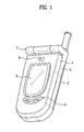
- Figure 1 illustrates a typical mobile communication terminal in the form of a mobile telephone having an integrated digital camera and audio player.
- a camera lens 4 is generally positioned at the top end of an upper housing 1.
- the lens 4 might be positioned on a hinge 7 joining the upper housing to a lower housing 2, or on a rear side of the lower housing 2.
- control keys 6, such as those shown in FIG. 1, are provided for controlling the audio player and are positioned on an outer surface of the upper housing 1.
- an auxiliary display 5 is typically positioned along a portion of the upper housing 1 so that a user can check a current time, caller information and the like without opening the upper housing 1.
- the need to provide all of these functional components - the lens 4, the control keys 6 and the auxiliary display 5 - within the relatively small space provided by the front surface of the upper housing 1 is difficult.
- this arrangement inevitably limits the size of the auxiliary display 5 that can be provided, or may limit the size and type of control keys 6 that might otherwise be provided, thereby limiting the usability of the mobile communication terminal.
- the lens 4 might be positioned on the hinge 7, or on the lower housing 2.
- the control keys 6 might be positioned on the main keypad (such as might be found on a typical mobile telephone, not shown in the drawing) that is provided on the lower housing 2 and accessible only when the mobile device is placed in an open position.
- these approaches are not entirely satisfactory because they all result in a device that is less convenient to use.
- the control keys 6 when the control keys 6 are positioned in the keypad disposed on the lower housing 2, it requires the user to first open the mobile communication terminal to use the audio player. This typically requires the use of two hands, and can be inconvenient.
- control keys 6 are situated at the positions shown in FIG. 1, it is difficult for a user holding the mobile communication terminal by one hand to press or otherwise manipulate the appropriate control key 6. In this case, a user usually presses the control keys 6 using the thumb of the hand that holds the mobile communication terminal. This type of operation is normally difficult and inconvenient. Hence, a user needs to use both hands to press the control keys 6 correctly - again, an operation that can be very inconvenient.
- a mobile communication device such as a cellular telephone, PDA or the like having integrated functions such as an audio player, with accessible and easy to use control keys.
- the present invention is directed to a mobile communication terminal that substantially obviates one or more problems due to limitations and disadvantages of the related art.
- An object of the present invention is to provide a mobile communication terminal having one or more control keys for controlling a functional component integrated with the mobile communication terminal, such as an integrated audio player.
- the control keys are situated on the mobile terminal so as to be convenient and easy to manipulate by a user of the device.
- Another object of the present invention is to provide a mobile communication terminal with the easy to use control key function, and yet do so in a manner that permits the implementation of a larger auxiliary display positioned on an exterior of the mobile communication terminal.
- the larger auxiliary display allows for more convenient operation and monitoring of the mobile terminal by a user.
- a mobile communication terminal such as a wireless telephone
- the device is disposed within a foldable, clamshell-like housing that includes an upper housing portion and a lower housing portion, which are rotatably connected via a hinge mechanism.
- the mobile communication terminal also includes additional functional components integrated within the device, such as an audio player, a digital camera and the like.
- a control key assembly that provides at least one control key for operating the integrated functional component.
- the control key assembly is conveniently positioned on at least one lateral side of the housing of the mobile device and situated so as to allow easy access by a user to operate the audio player.
- the mobile communication terminal further includes an auxiliary display positioned on an outer surface of the upper housing portion, such that the display is visible to a user when the mobile device is folded about the hinge in a closed position.
- the display can be used for showing any information pertinent to the mobile communication device. In the case of a mobile telephone, the information might include incoming call information, current date and time, and the like.
- the auxiliary display could also be used to display information pertinent to the integrated functional component, such as status or volume information for an audio player.
- the mobile terminal device has a clamshell-like design, where upper and lower housing portions are joined by a hinge assembly.
- the hinge assembly includes a central portion having end portions.
- the control key assembly is formed on one or both of the end portions.
- the control keys are mechanically and electrically interfaced with circuitry internal to the housing so as to permit control of a function of the mobile terminal device, such as an integrated audio player. For example, manipulation of the control keys might control the "play" or "stop” function of the audio player.
- Providing the keys in the hinge assembly provides an efficient use of physical space, and also ensures easy, one handed operation by the user. Importantly, the user can manipulate the operation of the audio player (or other integrated function) without having to "open" the mobile terminal.
- a speaker is also provided within each of the end portions of the hinge assembly.
- an audio player may utilize the speakers for the playback of audio.
- the control keys are implemented so as to be functionally integrated with the speaker structure. This approach provides the additional audio function, and yet does so in a manner that utilizes minimal physical space. Again, this approach maximizes the space available to, for example, the auxiliary display, which can now be a larger size.
- FIG. 1 is a perspective diagram of a mobile communication terminal according to a related art
- FIG. 2 is a block diagram of a mobile communication terminal according to the present invention.
- FIG. 3A and FIG. 3B are perspective diagrams of a mobile communication terminal according to a first embodiment of the present invention.
- FIG. 4A is a diagram of a control key assembly of an audio assembly and speaker joined to a hinge in the mobile communication terminal in FIG. 3A and FIG. 3B;
- FIG. 4B is a cross-sectional diagram of a modification of the control key assembly in FIG. 4A;
- FIG. 5A and FIG. 5B are perspective diagrams of another example of a hold key of the mobile communication terminal in FIG. 3A and FIG. 3B;
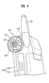
- FIG. 6 is a perspective diagram of a mobile communication terminal according to a second embodiment of the present invention.
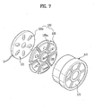
- FIG. 7 is an exploded perspective diagram of a control key assembly of an audio player in the mobile communication terminal in FIG. 6;
- FIG. 8 is an exploded perspective diagram of a modification of a control key assembly of an audio player in the mobile communication terminal in FIG. 6;
- FIG. 9 is an exploded perspective diagram of another modification of a control key assembly of an audio player in the mobile communication terminal in FIG. 6.
- FIG. 2 is a block diagram of a mobile communication terminal according to an example of a preferred embodiment of the present invention.
- the mobile communication terminal is shown herein as comprising a mobile telephone.
- PDAs personal digital assistants
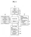
- a mobile communication terminal according to an example embodiment includes a control unit 10, an input/output unit 20, a mobile communication processing unit 30 for enabling wireless communications with an external device, a digital camera functional component 50 capable of capturing digital images, and an audio player 40 for playing audio files.
- the above mentioned parts are built in or on a housing 200 (illustrated in FIG. 3A).
- the input/output unit 20 includes a keypad 21 that can be activated by a user to operate the mobile terminal, a microphone 23 capable of receiving a voice input, a speaker 25 for outputting audio, and a display 27 for displaying textual or graphical information.
- the mobile communication signal processing unit 30 can include, for example, a transmission/reception circuit 31 and an antenna 33 for outputting a wireless signal processed by the transmission/reception circuit 31 or receiving an external wireless signal.
- the transmission/reception circuit 31 includes a transmission signal processing unit and a reception signal processing unit (not shown in the drawing).
- the transmission signal processing unit is generally configured to cause the wireless transmission of a signal such as information inputted via the input/output unit 20 (e.g., the voice of a user) or information stored in a memory 11 of the control unit 10.
- the reception signal processing unit is configured for receiving and processing external wireless signals received by the mobile communication terminal.
- the mobile communication signal processing unit 30 allows the mobile communication terminal to wirelessly communicate with an external device, e.g., a base station.
- the audio player component 40 is configured to output an audio file that is stored within a memory location, such as the memory 11 of the control unit 10.
- the audio player 40 might be configured to output an audio file stored in the MP3 file format.
- the audio player includes a file reproduction processing unit 41 configured for processing the audio file, a speaker 43 capable of outputting the audio signal, and a control key assembly 100 that provides a user with the ability to control the functionality of audio player 40, such as volume, playback, audio file selection, and the like.
- the speaker 25 of the input/output unit 20 could be used as the audio player speaker 43.
- the speaker 43 of the audio player 40 is preferably separate from the speaker 25 of the input-output unit 20 to provide a better quality of sound.
- the speaker 43 can be provided as an integrated and discrete speaker, or an audio output component for supplying the audio signal to headphones or other external speaker system, or both.
- the keypad 21 of the input/output unit 20 could be used to provide the functionality of the audio player control key assembly 100.
- the control key assembly 100 is separate from the main keypad 21 to provide the user with the ability to conveniently operate and control the audio player 40 functions.
- a camera 50 can also be provided as an integrated functional component of the mobile communication terminal.
- the camera 50 includes a lens 51, a photo-sensor 53 for converting light through the lens to an analog signal, and a DSP (digital signal processor) 55 for converting the analog signal to a digital signal.
- DSP digital signal processor
- control unit 10 input/output unit 20
- mobile communication signal processing unit 30 mobile communication signal processing unit 30
- camera 50 camera 50
- the mobile communication terminal according to the present invention differs from a conventional mobile communication terminal in that the control key assembly 100 for controlling the audio player 40 is positioned so as to be more accessible and easy to use for the user. Examples of this improved configuration are described below.
- a control key assembly 100 for handling an audio player 40 is positioned on lateral sides of a housing 200.
- a user can conveniently access and activate the individual keys on the control key assembly 100 using the thumb and the forefinger or the middle finger, while holding the housing 200 of the mobile communication terminal in one hand.
- the control key assembly 100 is positioned on an upper part of the lateral side of the housing in the manner shown.
- the exact positioning of the key assembly 100 might be varied so as to provide accessibility with different finger combinations and/or positions, depending on the particular needs addressed.
- the mobile terminal includes a hinge mechanism 250, an upper housing 220 and a lower housing 210.
- the upper and lower housings 220 and 210 are rotatably joined together via the hinge mechanism 250.
- a keypad 21 and a microphone 23 are positioned on an inner surface of the lower housing 210. This inner surface abuts the upper housing 220 when the housing 200 is folded in a closed position (shown in Figures 3A and 3B).
- a battery (not shown in the drawing) is removably connected to an outer surface of the lower housing 210, i.e., a surface opposite to the keypad-provided surface.
- Figure 4A further illustrates how a display 27 and a speaker 25 are positioned on an inner surface of the upper housing 220, i.e., the surface that abuts the keypad 21 when the housing 200 is folded in a closed position.
- an auxiliary display 27a can be positioned on an outer surface of the upper housing 220, i.e., a surface facing outward when the housing 200 is folded in a closed position.
- the auxiliary display 27a can, for example, be configured to display to a user information such as the current time, caller identification information, received message information, and the like, and does so without requiring the user to open the housing.
- the hinge 250 includes a central portion 251 and a pair of end portions 252.
- the central portion 251 is configured so as to extend from a top end of the upper housing 220.
- the end portions 252 each extend from opposing sides of an upper end of the lower housing 210 so as to be separated by a predetermined distance.
- the central portion 251, as shown in FIG. 4A is situated between the end portions 252 so as to join the upper and lower housings 220 and 210 together.
- this configuration is but one example of the manner in which the hinge 250 can be structured so as to rotatably connect the lower housing to the upper housing.
- the central portion 251 might instead extend from the lower housing 210, and the end portions 252 extend from the upper housing.
- the hinge 250 is preferably arranged substantially parallel to the upper and lower housings 220 and 210.
- the control key assembly 100 is preferably positioned on opposing end faces on each of the end portions 252, as is shown in Figures 3A and 3B together. To accomplish this, a space for installing the control key assembly 100, as shown in FIG. 4A, is provided along an internal section of each of the end portions 252, as is described in further detail below.
- the control key assembly 100 is installed within an internal space provided at each of the end portions 252 of the hinge 250.
- the control key assembly 100 includes a cap 110 and at least one control key 120 that can be activated by a user.
- a cap 110 as shown in FIG. 4A, is provided at each end portion 252 of the hinge 250.
- a control key 120 as shown in FIG. 3A and FIG. 3B, partially passes through the cap 110 to be exposed and thereby be accessible for actuation by a user. Hence, in the illustrated embodiment a user presses the exposed key 120 at the corresponding length-directional end of the hinge 250 to control or operate the audio player 40.
- the key 120 includes a resilient or soft- keypad 121 disposed within the cap 110, and a button 125 provided between the keypad 121 and the cap 110.
- the keypad 121 can be formed of a flexible printed circuit board of the sort used in a convention keypad on a typical mobile communication terminal, thereby reducing the amount of space needed.
- the keypad 121 is electrically connected to a main circuit board 201 disposed within the lower housing 210.
- the button 125 is formed of a substantially rigid or hard material, such as plastic, metal and the like.
- One side of the button 125 partially passes through the cap 110 so as to be externally exposed on one end, and the other end in contact with the keypad 121.
- a stepped portion 125a is provided to mechanically cooperate with the cap 110 so as to prevent the button 125 from escaping from the cap 110.
- the configuration of the key 120 is not limited to the above-explained structure.
- the key 120 may include only a keypad 121 formed from a soft or resilient material.
- one side of the keypad 121 as shown in FIG. 4B, partially passes through the cap 110 to be externally exposed.
- the cap 110 is preferably configured to have a structure in which the key 120 can be secured.
- the cap 110 includes a hollow frame 111 and a socket 140 provided within the frame 111.
- an open end portion of the frame 111 faces an inside of the hinge 250 so that the frame 111 is coupled with the end portion 252 of the hinge 250.
- the key 120 is loaded in the socket 140.
- the key 120 as shown in FIG. 4A, partially passes through the cap 110 to be externally exposed.
- the above-configured socket 140 as shown in FIG. 4A, is fixed to an inside of the frame 111 by a plurality of supports 113 protruding from an inner circumference of the frame 111.
- the socket 140 is arranged substantially at a center of the frame 111 to have the same central axis of the frame 111, for example.
- the socket 140 secures the key 120 and preferably has a configuration facilitating the key 120 to be loaded therein.
- the socket 140 may include several pieces.
- the socket 140 includes a cylinder 141 supported by the frame 111 and a cover 145 detachably assembled to one open end of the cylinder 141.
- the cylinder 141 has a pair of open ends, and the key 120 is loaded in the cylinder 141.
- An extension 143 is positioned on a first end portion of the cylinder 141 that opens to the outside of the frame 111 to prevent the key 120 loaded in the cylinder from escaping from the cylinder 141. Since the extension 143 protrudes toward a central axis of the cylinder 141 from the first end portion, the key 120 loaded in the cylinder 141 is unable to escape externally via the first end portion.
- the cover 145 is assembled to and encloses a second end portion of the cylinder 141, which opens to the inside of the frame 111. Hence, the cover 145 is fitted to the second end portion of the cylinder 141 after the key 120 has been loaded in the cylinder 141 and is thereby able to secure the key 120 in the socket 140.
- the mobile communication terminal further includes a speaker 43.
- the speaker 43 which can be used to output audio from the audio player 40, is positioned at the end portion 252 of the hinge 250 in a manner so as to be integrated with the control key assembly 100.
- the speaker 43 can be loaded in the end portion 252 of the hinge 250, and more particularly, in the frame 111 of the cap 110 for example.
- at least one hole 131 is formed in the hinge 250, preferably in the region of the cap 110, as is denoted in FIG. 4A.
- the hole 131 is preferably formed at the length-directional end portion of the hinge 250.
- the hole 131 can be formed along a circumference of the hinge 250.
- a plurality of holes 131 are formed in the in the vicinity of the key 120.
- the hole 131 can be provided in a different shape.
- a grill 130 having a plurality of holes 131 can be positioned at an area of the end portion of the cap 110 other than that which is occupied by the key 120.
- the grill 130 as shown in FIGs. 3A to 4A, can be positioned on the end portion of the cap 110 to surround an exposed portion of the key 120.
- the key 120 is arranged substantially at a center of the cap 110 and the grill 130 is arranged to surround the key 120.
- the grill 130 can be arranged in a reverse manner.
- the grill 130 as shown in FIG. 9, is arranged substantially at the center of the end portion of the cap 110 and a plurality of keys 120 are arranged in the vicinity of the grill 130 to surround the grill 130.
- control key assembly 100 can be positioned on each of a pair of length-directional end portions 252 of the hinge 250.
- the control key assembly 100 includes function keys enabling convenient operations of the audio player 40, e.g., a stop/play key 120a and a hold key 120b, and is preferably provided together with the speaker 43 loaded in the hinge 250.
- the stop/play key 120a is positioned on one of the two length-directional end portions 252 of the hinge 250 and the hold key 120b is positioned on the other. If the above-provided stop/play key 120a is pressed when the audio player 40 is not operating, the audio player 40 plays back a previously selected or stored music file. If the stop/play key 120a is pressed when the audio player 40 is operating, the played sound is stopped. If the hold key 120b is pressed, the operational state of the audio player 40 is not changed even though other control keys of the audio player 40 might be pressed. If the hold key 120b is pressed again after having been turned on, the hold mode is released, such that the operational state of the audio player 40 can be changed by other keys.
- the use of the hold key 120b effectively prevents the operation of the audio player 40 of the mobile communication terminal from being interrupted or changed by an unexpected external force as the mobile communication terminal is carried by a user.
- the hold key 120b becomes operative if it is pressed.
- the operational state of the audio player 40 could change if the hold key 120b and other control keys are sequentially pressed.
- the present invention provides a configuration that can prevent operational state from changing in this scenario.
- the hold key 120b becomes operative by being rotated instead of being pressed. Specifically, the hold key 120b becomes operative by being rotated about an axis substantially parallel to the length-directional end portion of the hinge 250. This can be easily implemented by means of a switch (not shown in the drawing) in the socket 140 that is driven in rotating the hold key 120b.
- a groove 151 or a protrusion 152 can be positioned on a surface of the hold key 120b to facilitate the rotation thereof.
- the groove 151 as shown in FIG. 5A, is preferably formed along an upper surface of the hold key 120b in a radial direction.
- the protrusion 152 as shown in FIG. 5B, is preferably formed on the upper surface of the hold key 120b in a radial direction.
- control key assembly 100 positioned on each of the two length-directional end portions 252 of the hinge 100 is explained in the above description.
- the control key assembly 100 can be positioned on only one of the two length-directional end portions 252 of the hinge 100. In this case, it is advantageous to provide a different part, such as a camera 50 or the like, on the other length-directional end portion 252 of the hinge 100.
- control key assembly 100 is positioned on only one of the two length-directional end portions 252 of the hinge 100, the control key assembly 100 preferably includes several control keys 120.
- FIGs. 6 to 9 show a control key assembly according to a second embodiment of the present invention, in which several keys 120 are positioned on one control key assembly 100.
- a mobile communication terminal according to a second embodiment of the present invention is explained in detail with reference to FIGs. 6 to 9 as follows.
- the keys 120 are positioned on a control key assembly 100 according to a second embodiment of the present invention.
- the keys 120 of the control key assembly 100 occupy the majority of a lateral side of the end portion 252 of the hinge 250.
- the keys 120 may include, for example, a stop key 120d, a play key 120c, a forward key 120e, a backward key 120f, an up key 120g, a down key 120h and a hold key 120b.
- the number and types of the keys can be modified to provide the desired functions.
- a plurality of button holes 115 are formed at one end of the cap 110 to enable a plurality of the keys to be loaded therein. Specifically, a button hole 115 corresponding to each of the keys 120 is formed in the end of the cap 110. And, a plurality of buttons 125 fitted in the button holes 115, respectively, and a keypad 121 are provided within the cap 110.
- a stepped portion 125a is positioned on each of the buttons 125 to prevent the corresponding button 125 from escaping via the corresponding button hole 115.
- a plurality of switches 121a are positioned on areas of the keypad 121, as shown in FIG. 7, corresponding to the buttons 125, respectively.
- the switch 121a of the keypad 121 brought into contact with the pressed button 125 is pressed to operate the audio player 40.
- each of the keys 120 of the control key assembly 100 has one corresponding button 125 and one corresponding switch 121a.
- the control key assembly 100 according to the second embodiment of the present invention is not limited to the foregoing example, but can instead be implemented in another example.
- one button 125 as shown in FIG. 8, which can be obliquely pressed against a central axis, can selectively press various switches 121a positioned on the keypad 121.
- one large button hole 115 is positioned on an end portion of the cap 110 coupled with the end portion 252 of the hinge 250.
- the keypad 121 is located within the cap 110 and includes a plurality of the switches 121a for operating the audio player 40, which are arranged along an inner circumference of the cap 110.
- one button 125 is provided between the button hole 115 and the keypad 121 to be obliquely pressed against the keypad 121.
- the button 125 is fitted in the button hole 115, and a support shaft 125b, as indicated by a dotted line in FIG. 8, protrudes from a center of the button 125.
- the button 125 is obliquely pressed against its center when a user presses a portion of the button 125 that is radially displaced from its center. Pressing the button 125 in this manner causes one of the switches 121a along the circumference of the keypad 121 to be pressed.
- the control key assembly 100 can be assembled to the end portion 252 of the hinge 250 together with the speaker 43.
- the grill 130 for transferring sound of the speaker 43 externally is arranged substantially at a center of the end portion of the hinge 250, and the keys 120 of the control key assembly 100 are arranged to surround the grill 130.
- a user presses the stop/play key 120a in FIG. 3A or the play key 120c in FIG. 6 while the housing 200 is folded. This results in the control unit 10 entering the mode for controlling the audio player 40, and an audio file list and a menu for controlling the audio player 40 are displayed on the auxiliary display 27a on the upper housing 220.
- the user can search and select the audio file list and the menu using the up and down keys 211 and 213 and the stop/play key 120a in FIG. 3A.
- the up and down keys 211 and 213, as shown in FIG. 3B, are similar to those that are positioned on the lateral side of the housing 200 of a conventional mobile communication terminal to raise or lower the volume.
- the up and down keys 211 and 213 can be used in searching the file and menu in a control mode of the audio player 40.
- the user can press the hold key 120b in FIG. 3B or FIG. 6.
- the hold key 120b is pressed, the operational state of the audio player 40 will not change even if any other keys are pressed.
- the user wants to intentionally stop the playback or change the operational state of the audio player 40, by pressing the hold key 120 once again to deactivate the hold function. The user can then stop the playback of the audio player 40 or change the operational state of the audio player 40 by pressing another key.
- the playback of the sound is stopped if the user presses the stop/play key 120a in FIG. 3A or the stop key 120d in FIG. 6 while the sound is played back. If necessary, this involves searching the menu and selecting an audio player end item from the menu. Of course, if the stop key 120d is pressed once again after the playback of the sound has stopped, the audio player 40 is turned off.
- a user can use the audio player very conveniently without unfolding the mobile communication terminal.
- positioning the keys for operating the audio player on the lateral sides of the housing e.g., both of the lateral end portions of the hinge joining the upper and lower housings together, assists the user in pressing the keys using the thumb, forefinger, middle finger and third finger.
- a wider auxiliary display on the upper surface of the housing, e.g., the outer surface of the upper housing, than would otherwise be possible if the keys for operating the audio player were positioned on the outer surface of the upper housing.
- the present invention efficiently utilizes the space to enable a compact size of the housing.
- the hold key is positioned on the control key assembly for operating the audio player and operates by being rotated.
- this embodiment of the present invention effectively prevents the operational state of the audio player from being easily changed by other keys that might be pressed by an unexpected external force when the terminal is being carried.
- control key assembly is positioned on one of the end portions of the hinge, a camera lens can be positioned on the other end portion to efficiently use space. Moreover, positioning a plurality of keys on the control key assembly permits a user to conveniently use various functions of the audio player.
- control keys have been described in connection with the control and operation of an integrated audio player, that they should not be viewed as being limited to that specific use.
- control key configuration would find applicability in connection with the operation and control of any functional component of the mobile communication device, including other audio and/or video functions.
Abstract
Description
- This application claims the benefit of the Korean Application No. 10-2004-0078703 filed on October 4, 2004, which is hereby incorporated herein by reference.
- The present invention relates to a mobile communication terminal, and more particularly, to a mobile communication terminal provided with dedicated control keys that are positioned so as to be conveniently accessed and easy to use for controlling the operation of a functional component integrated in the mobile terminal, such as an audio player.
- Originally, mobile communication devices such as mobile phones, personal digital assistants (PDAs) and the like were dedicated to one or two functions, such as wireless voice communications. However, as technology has advanced, so have the relative capabilities of these devices. For example, such mobile communications devices incorporate increasingly sophisticated technologies and, as a result, provide additional functions. For example, wireless mobile telephones now typically include features such as digital displays for displaying character and image information, gaming functions and the like in addition to simple voice capabilities. Integration of functional components continues. For example, mobile communication terminals, such as the type shown in FIG. 1, are now commonly offered with features such as an audio player function for playing back audio files, and a digital camera function for capturing digital photos and videos.
- While users continue to demand this type of increased functionality, there is an ongoing effort to insure that the devices are provided within smaller and smaller form factors. The ability to provide additional functionality along with a small form factor has, however, created problems with respect to usability of these devices. In particular, small sizes and increased functions can result in a device that is more difficult to use and control on the part of a user. For example, in a device having an integrated camera and audio player function, the need to position a camera lens as well as control keys for operating and controlling the audio player can be problematic - especially in a device having a small form factor. The device shown in Figure 1 is illustrative of this particular problem.
- Figure 1 illustrates a typical mobile communication terminal in the form of a mobile telephone having an integrated digital camera and audio player. In this type of environment, a
camera lens 4, is generally positioned at the top end of anupper housing 1. Alternatively, thelens 4 might be positioned on ahinge 7 joining the upper housing to alower housing 2, or on a rear side of thelower housing 2. Typically,control keys 6, such as those shown in FIG. 1, are provided for controlling the audio player and are positioned on an outer surface of theupper housing 1. - In addition to the control keys and the lens, , an
auxiliary display 5, as shown in FIG. 1, is typically positioned along a portion of theupper housing 1 so that a user can check a current time, caller information and the like without opening theupper housing 1. As will be appreciated, the need to provide all of these functional components - thelens 4, thecontrol keys 6 and the auxiliary display 5 - within the relatively small space provided by the front surface of theupper housing 1 is difficult. For example, this arrangement inevitably limits the size of theauxiliary display 5 that can be provided, or may limit the size and type ofcontrol keys 6 that might otherwise be provided, thereby limiting the usability of the mobile communication terminal. - Previous solutions to this problem have not been completely satisfactory. For example, in designing the terminal to increase the size of the
auxiliary display 5, thelens 4 might be positioned on thehinge 7, or on thelower housing 2. Or, thecontrol keys 6 might be positioned on the main keypad (such as might be found on a typical mobile telephone, not shown in the drawing) that is provided on thelower housing 2 and accessible only when the mobile device is placed in an open position. However, these approaches are not entirely satisfactory because they all result in a device that is less convenient to use. For example, when thecontrol keys 6 are positioned in the keypad disposed on thelower housing 2, it requires the user to first open the mobile communication terminal to use the audio player. This typically requires the use of two hands, and can be inconvenient. - Moreover, if the
control keys 6 are situated at the positions shown in FIG. 1, it is difficult for a user holding the mobile communication terminal by one hand to press or otherwise manipulate theappropriate control key 6. In this case, a user usually presses thecontrol keys 6 using the thumb of the hand that holds the mobile communication terminal. This type of operation is normally difficult and inconvenient. Hence, a user needs to use both hands to press thecontrol keys 6 correctly - again, an operation that can be very inconvenient. - Thus, in view of the above problems it would be desirable to provide a mobile communication device, such as a cellular telephone, PDA or the like having integrated functions such as an audio player, with accessible and easy to use control keys.
- The present invention is directed to a mobile communication terminal that substantially obviates one or more problems due to limitations and disadvantages of the related art.
- An object of the present invention is to provide a mobile communication terminal having one or more control keys for controlling a functional component integrated with the mobile communication terminal, such as an integrated audio player. Preferably, the control keys are situated on the mobile terminal so as to be convenient and easy to manipulate by a user of the device.
- Another object of the present invention is to provide a mobile communication terminal with the easy to use control key function, and yet do so in a manner that permits the implementation of a larger auxiliary display positioned on an exterior of the mobile communication terminal. The larger auxiliary display allows for more convenient operation and monitoring of the mobile terminal by a user.
- Additional advantages, objects, and features of the invention will be set forth in part in the description which follows and in part will become apparent to those having ordinary skill in the art upon examination of the following or may be learned from practice of the invention. The objectives and other advantages of the invention may be realized and attained by the structure particularly pointed out in the written description and claims hereof as well as the appended drawings.
- To achieve these objects and other advantages and in accordance with the purpose of the invention, as embodied and broadly described herein, a mobile communication terminal, such as a wireless telephone, is provided. In example embodiments, the device is disposed within a foldable, clamshell-like housing that includes an upper housing portion and a lower housing portion, which are rotatably connected via a hinge mechanism. In preferred embodiments, the mobile communication terminal also includes additional functional components integrated within the device, such as an audio player, a digital camera and the like. Also included is a control key assembly that provides at least one control key for operating the integrated functional component. For example, in a preferred embodiment, the control key assembly is conveniently positioned on at least one lateral side of the housing of the mobile device and situated so as to allow easy access by a user to operate the audio player.
- In a preferred embodiment, the mobile communication terminal further includes an auxiliary display positioned on an outer surface of the upper housing portion, such that the display is visible to a user when the mobile device is folded about the hinge in a closed position. The display can be used for showing any information pertinent to the mobile communication device. In the case of a mobile telephone, the information might include incoming call information, current date and time, and the like. The auxiliary display could also be used to display information pertinent to the integrated functional component, such as status or volume information for an audio player.
- As noted above, in preferred embodiments, the mobile terminal device has a clamshell-like design, where upper and lower housing portions are joined by a hinge assembly. In illustrated embodiments, the hinge assembly includes a central portion having end portions. To maximize space as well as enhancing accessibility, the control key assembly is formed on one or both of the end portions. The control keys are mechanically and electrically interfaced with circuitry internal to the housing so as to permit control of a function of the mobile terminal device, such as an integrated audio player. For example, manipulation of the control keys might control the "play" or "stop" function of the audio player. Providing the keys in the hinge assembly provides an efficient use of physical space, and also ensures easy, one handed operation by the user. Importantly, the user can manipulate the operation of the audio player (or other integrated function) without having to "open" the mobile terminal.
- In yet a further embodiment, a speaker is also provided within each of the end portions of the hinge assembly. In this way, an audio player may utilize the speakers for the playback of audio. In this embodiment, the control keys are implemented so as to be functionally integrated with the speaker structure. This approach provides the additional audio function, and yet does so in a manner that utilizes minimal physical space. Again, this approach maximizes the space available to, for example, the auxiliary display, which can now be a larger size.
- It is to be understood that both the foregoing general description and the following detailed description of the present invention are exemplary and explanatory and are intended to provide further explanation of the invention as claimed.
- The accompanying drawings, which are included to provide a further understanding of the invention and are incorporated in and constitute a part of this application, illustrate embodiment(s) of the invention and together with the description serve to explain the principle of the invention. In the drawings:
- FIG. 1 is a perspective diagram of a mobile communication terminal according to a related art;
- FIG. 2 is a block diagram of a mobile communication terminal according to the present invention;
- FIG. 3A and FIG. 3B are perspective diagrams of a mobile communication terminal according to a first embodiment of the present invention;
- FIG. 4A is a diagram of a control key assembly of an audio assembly and speaker joined to a hinge in the mobile communication terminal in FIG. 3A and FIG. 3B;
- FIG. 4B is a cross-sectional diagram of a modification of the control key assembly in FIG. 4A;
- FIG. 5A and FIG. 5B are perspective diagrams of another example of a hold key of the mobile communication terminal in FIG. 3A and FIG. 3B;
- FIG. 6 is a perspective diagram of a mobile communication terminal according to a second embodiment of the present invention;
- FIG. 7 is an exploded perspective diagram of a control key assembly of an audio player in the mobile communication terminal in FIG. 6;
- FIG. 8 is an exploded perspective diagram of a modification of a control key assembly of an audio player in the mobile communication terminal in FIG. 6; and
- FIG. 9 is an exploded perspective diagram of another modification of a control key assembly of an audio player in the mobile communication terminal in FIG. 6.
- Reference will now be made in detail to the preferred embodiments of the present invention, examples of which are illustrated in the accompanying drawings. Wherever possible, the same reference numbers will be used throughout the drawings to refer to the same or like parts.
- FIG. 2 is a block diagram of a mobile communication terminal according to an example of a preferred embodiment of the present invention. For purposes of illustration, the mobile communication terminal is shown herein as comprising a mobile telephone. However, it will be appreciated that the invention is not limited to such an environment, and can be implemented in any one of a number of different environments; including but not limited to personal digital assistants (PDAs) and similar handheld computing or communication devices. Referring to FIG. 2, a mobile communication terminal according to an example embodiment includes a
control unit 10, an input/output unit 20, a mobilecommunication processing unit 30 for enabling wireless communications with an external device, a digital camerafunctional component 50 capable of capturing digital images, and anaudio player 40 for playing audio files. The above mentioned parts are built in or on a housing 200 (illustrated in FIG. 3A). - In this example embodiment, the input/
output unit 20 includes akeypad 21 that can be activated by a user to operate the mobile terminal, amicrophone 23 capable of receiving a voice input, aspeaker 25 for outputting audio, and adisplay 27 for displaying textual or graphical information. - The mobile communication
signal processing unit 30 can include, for example, a transmission/reception circuit 31 and anantenna 33 for outputting a wireless signal processed by the transmission/reception circuit 31 or receiving an external wireless signal. In addition, the transmission/reception circuit 31 includes a transmission signal processing unit and a reception signal processing unit (not shown in the drawing). The transmission signal processing unit is generally configured to cause the wireless transmission of a signal such as information inputted via the input/output unit 20 (e.g., the voice of a user) or information stored in amemory 11 of thecontrol unit 10. The reception signal processing unit is configured for receiving and processing external wireless signals received by the mobile communication terminal. In general, the mobile communicationsignal processing unit 30 allows the mobile communication terminal to wirelessly communicate with an external device, e.g., a base station. - As is further depicted in Figure 2, the
audio player component 40 is configured to output an audio file that is stored within a memory location, such as thememory 11 of thecontrol unit 10. For example, theaudio player 40 might be configured to output an audio file stored in the MP3 file format.. For this, the audio player includes a filereproduction processing unit 41 configured for processing the audio file, aspeaker 43 capable of outputting the audio signal, and a controlkey assembly 100 that provides a user with the ability to control the functionality ofaudio player 40, such as volume, playback, audio file selection, and the like. - It will be appreciated that the
speaker 25 of the input/output unit 20 could be used as theaudio player speaker 43. However, thespeaker 43 of theaudio player 40 is preferably separate from thespeaker 25 of the input-output unit 20 to provide a better quality of sound. Thespeaker 43 can be provided as an integrated and discrete speaker, or an audio output component for supplying the audio signal to headphones or other external speaker system, or both. Likewise, thekeypad 21 of the input/output unit 20 could be used to provide the functionality of the audio player controlkey assembly 100. Preferably, the controlkey assembly 100 is separate from themain keypad 21 to provide the user with the ability to conveniently operate and control theaudio player 40 functions. - As is further shown in FIG. 2, a
camera 50 can also be provided as an integrated functional component of the mobile communication terminal. In the example embodiment, thecamera 50 includes alens 51, a photo-sensor 53 for converting light through the lens to an analog signal, and a DSP (digital signal processor) 55 for converting the analog signal to a digital signal. - Configurations of the above-described
control unit 10, input/output unit 20, mobile communicationsignal processing unit 30,audio player 40 andcamera 50 are similar to those of a conventional mobile communication terminal. Such devices are well known in the art and thus not described further However, the mobile communication terminal according to the present invention differs from a conventional mobile communication terminal in that the controlkey assembly 100 for controlling theaudio player 40 is positioned so as to be more accessible and easy to use for the user. Examples of this improved configuration are described below. - Referring first to FIG. 3A and FIG. 3B together, a control
key assembly 100 for handling anaudio player 40 is positioned on lateral sides of ahousing 200. When positioned in this manner, a user can conveniently access and activate the individual keys on the controlkey assembly 100 using the thumb and the forefinger or the middle finger, while holding thehousing 200 of the mobile communication terminal in one hand. In one preferred embodiment, the controlkey assembly 100 is positioned on an upper part of the lateral side of the housing in the manner shown. However, it will be appreciated that the exact positioning of thekey assembly 100 might be varied so as to provide accessibility with different finger combinations and/or positions, depending on the particular needs addressed. - While not so limited, this particular configuration finds particular applicability in any kind of mobile communication terminal having a bar, flip or slide type housing.
- In the example embodiment shown in FIGs. 3A to 4A, the mobile terminal includes a
hinge mechanism 250, anupper housing 220 and alower housing 210. The upper andlower housings hinge mechanism 250. - As is shown in FIG. 4A, a
keypad 21 and amicrophone 23 are positioned on an inner surface of thelower housing 210. This inner surface abuts theupper housing 220 when thehousing 200 is folded in a closed position (shown in Figures 3A and 3B). In the example embodiment, a battery (not shown in the drawing) is removably connected to an outer surface of thelower housing 210, i.e., a surface opposite to the keypad-provided surface. - Figure 4A further illustrates how a
display 27 and aspeaker 25 are positioned on an inner surface of theupper housing 220, i.e., the surface that abuts thekeypad 21 when thehousing 200 is folded in a closed position. As is also shown in Figures 3A and 3B, anauxiliary display 27a can be positioned on an outer surface of theupper housing 220, i.e., a surface facing outward when thehousing 200 is folded in a closed position. Theauxiliary display 27a can, for example, be configured to display to a user information such as the current time, caller identification information, received message information, and the like, and does so without requiring the user to open the housing. - In the embodiment shown in Figures 3A through 4A, the
hinge 250 includes acentral portion 251 and a pair ofend portions 252. Thecentral portion 251 is configured so as to extend from a top end of theupper housing 220. Theend portions 252 each extend from opposing sides of an upper end of thelower housing 210 so as to be separated by a predetermined distance. Thecentral portion 251, as shown in FIG. 4A, is situated between theend portions 252 so as to join the upper andlower housings hinge 250 can be structured so as to rotatably connect the lower housing to the upper housing. For example, in an alternative configuration, thecentral portion 251 might instead extend from thelower housing 210, and theend portions 252 extend from the upper housing. - The
hinge 250 is preferably arranged substantially parallel to the upper andlower housings key assembly 100 is preferably positioned on opposing end faces on each of theend portions 252, as is shown in Figures 3A and 3B together. To accomplish this, a space for installing the controlkey assembly 100, as shown in FIG. 4A, is provided along an internal section of each of theend portions 252, as is described in further detail below. - The control
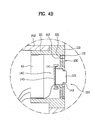
key assembly 100, as shown in FIG. 4A, is installed within an internal space provided at each of theend portions 252 of thehinge 250. The controlkey assembly 100 includes acap 110 and at least onecontrol key 120 that can be activated by a user. Acap 110, as shown in FIG. 4A, is provided at eachend portion 252 of thehinge 250. Acontrol key 120, as shown in FIG. 3A and FIG. 3B, partially passes through thecap 110 to be exposed and thereby be accessible for actuation by a user. Hence, in the illustrated embodiment a user presses the exposed key 120 at the corresponding length-directional end of thehinge 250 to control or operate theaudio player 40. - In the example embodiment, the key 120 includes a resilient or soft-
keypad 121 disposed within thecap 110, and abutton 125 provided between thekeypad 121 and thecap 110. Thekeypad 121 can be formed of a flexible printed circuit board of the sort used in a convention keypad on a typical mobile communication terminal, thereby reducing the amount of space needed. Thekeypad 121 is electrically connected to amain circuit board 201 disposed within thelower housing 210. - In a preferred embodiment the
button 125 is formed of a substantially rigid or hard material, such as plastic, metal and the like. One side of thebutton 125, as shown in FIG. 4A, partially passes through thecap 110 so as to be externally exposed on one end, and the other end in contact with thekeypad 121. Hence, when a user presses thebutton 125, thebutton 125 engages and activates thekeypad 121. Moreover, a steppedportion 125a, as shown in FIG. 4A, is provided to mechanically cooperate with thecap 110 so as to prevent thebutton 125 from escaping from thecap 110. - The configuration of the key 120 is not limited to the above-explained structure. For instance, the key 120, as shown in FIG. 4B, may include only a
keypad 121 formed from a soft or resilient material. In this case, one side of thekeypad 121, as shown in FIG. 4B, partially passes through thecap 110 to be externally exposed. - In addition, the
cap 110 is preferably configured to have a structure in which the key 120 can be secured. In the illustrated embodiment, thecap 110 includes ahollow frame 111 and asocket 140 provided within theframe 111. In this case, an open end portion of theframe 111 faces an inside of thehinge 250 so that theframe 111 is coupled with theend portion 252 of thehinge 250. And, the key 120 is loaded in thesocket 140. The key 120, as shown in FIG. 4A, partially passes through thecap 110 to be externally exposed. The above-configuredsocket 140, as shown in FIG. 4A, is fixed to an inside of theframe 111 by a plurality ofsupports 113 protruding from an inner circumference of theframe 111. Thesocket 140 is arranged substantially at a center of theframe 111 to have the same central axis of theframe 111, for example. - The
socket 140 secures the key 120 and preferably has a configuration facilitating the key 120 to be loaded therein. For this, thesocket 140, as shown in FIG. 4A, may include several pieces. For instance, thesocket 140 includes acylinder 141 supported by theframe 111 and acover 145 detachably assembled to one open end of thecylinder 141. - In this case, the
cylinder 141 has a pair of open ends, and the key 120 is loaded in thecylinder 141. Anextension 143, as shown in FIG. 4A, is positioned on a first end portion of thecylinder 141 that opens to the outside of theframe 111 to prevent the key 120 loaded in the cylinder from escaping from thecylinder 141. Since theextension 143 protrudes toward a central axis of thecylinder 141 from the first end portion, the key 120 loaded in thecylinder 141 is unable to escape externally via the first end portion. Thecover 145 is assembled to and encloses a second end portion of thecylinder 141, which opens to the inside of theframe 111. Hence, thecover 145 is fitted to the second end portion of thecylinder 141 after the key 120 has been loaded in thecylinder 141 and is thereby able to secure the key 120 in thesocket 140. - As is illustrated in FIG. 4A, in a preferred embodiment the mobile communication terminal further includes a
speaker 43. The speaker 43which can be used to output audio from theaudio player 40, is positioned at theend portion 252 of thehinge 250 in a manner so as to be integrated with the controlkey assembly 100. - The
speaker 43, as indicated by a solid line in FIG. 4A, can be loaded in theend portion 252 of thehinge 250, and more particularly, in theframe 111 of thecap 110 for example. In this case, at least onehole 131 is formed in thehinge 250, preferably in the region of thecap 110, as is denoted in FIG. 4A. In this case, thehole 131 is preferably formed at the length-directional end portion of thehinge 250. Alternatively, thehole 131 can be formed along a circumference of thehinge 250. In preferred embodiments, a plurality ofholes 131 are formed in the in the vicinity of the key 120. - Alternatively, the
hole 131 can be provided in a different shape. For instance, agrill 130 having a plurality ofholes 131 can be positioned at an area of the end portion of thecap 110 other than that which is occupied by the key 120. Specifically, thegrill 130, as shown in FIGs. 3A to 4A, can be positioned on the end portion of thecap 110 to surround an exposed portion of the key 120. In other words, the key 120 is arranged substantially at a center of thecap 110 and thegrill 130 is arranged to surround the key 120. Alternatively, thegrill 130 can be arranged in a reverse manner. For instance, thegrill 130, as shown in FIG. 9, is arranged substantially at the center of the end portion of thecap 110 and a plurality ofkeys 120 are arranged in the vicinity of thegrill 130 to surround thegrill 130. - The above-configured control
key assembly 100, as shown in FIG. 3A and FIG. 3B, can be positioned on each of a pair of length-directional end portions 252 of thehinge 250. In this case, the controlkey assembly 100 includes function keys enabling convenient operations of theaudio player 40, e.g., a stop/play key 120a and ahold key 120b, and is preferably provided together with thespeaker 43 loaded in thehinge 250. - By way of example, the stop/
play key 120a, as shown in Fig. 3A, is positioned on one of the two length-directional end portions 252 of thehinge 250 and thehold key 120b is positioned on the other. If the above-provided stop/play key 120a is pressed when theaudio player 40 is not operating, theaudio player 40 plays back a previously selected or stored music file. If the stop/play key 120a is pressed when theaudio player 40 is operating, the played sound is stopped. If thehold key 120b is pressed, the operational state of theaudio player 40 is not changed even though other control keys of theaudio player 40 might be pressed. If thehold key 120b is pressed again after having been turned on, the hold mode is released, such that the operational state of theaudio player 40 can be changed by other keys. - The use of the hold key 120b effectively prevents the operation of the
audio player 40 of the mobile communication terminal from being interrupted or changed by an unexpected external force as the mobile communication terminal is carried by a user. However, thehold key 120b becomes operative if it is pressed. Hence, in these circumstances, the operational state of theaudio player 40 could change if thehold key 120b and other control keys are sequentially pressed. The present invention provides a configuration that can prevent operational state from changing in this scenario. - To prevent this situation from occurring, the
hold key 120b, as shown in FIG. 5A and FIG. 5B, becomes operative by being rotated instead of being pressed. Specifically, thehold key 120b becomes operative by being rotated about an axis substantially parallel to the length-directional end portion of thehinge 250. This can be easily implemented by means of a switch (not shown in the drawing) in thesocket 140 that is driven in rotating thehold key 120b. - Optionally, a
groove 151 or aprotrusion 152 can be positioned on a surface of thehold key 120b to facilitate the rotation thereof. Thegroove 151, as shown in FIG. 5A, is preferably formed along an upper surface of thehold key 120b in a radial direction. Theprotrusion 152, as shown in FIG. 5B, is preferably formed on the upper surface of thehold key 120b in a radial direction. - The example of the control
key assembly 100 positioned on each of the two length-directional end portions 252 of thehinge 100 is explained in the above description. Alternatively, the controlkey assembly 100 can be positioned on only one of the two length-directional end portions 252 of thehinge 100. In this case, it is advantageous to provide a different part, such as acamera 50 or the like, on the other length-directional end portion 252 of thehinge 100. - If the control
key assembly 100 is positioned on only one of the two length-directional end portions 252 of thehinge 100, the controlkey assembly 100 preferably includesseveral control keys 120. FIGs. 6 to 9 show a control key assembly according to a second embodiment of the present invention, in whichseveral keys 120 are positioned on one controlkey assembly 100. A mobile communication terminal according to a second embodiment of the present invention is explained in detail with reference to FIGs. 6 to 9 as follows. - Referring to FIG. 6,
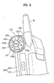
several keys 120 are positioned on a controlkey assembly 100 according to a second embodiment of the present invention. Thekeys 120 of the controlkey assembly 100 occupy the majority of a lateral side of theend portion 252 of thehinge 250. Thekeys 120 may include, for example, a stop key 120d, a play key 120c, a forward key 120e, a backward key 120f, an up key 120g, a down key 120h and ahold key 120b. The number and types of the keys can be modified to provide the desired functions. - A plurality of button holes 115, as shown in FIG. 7, are formed at one end of the
cap 110 to enable a plurality of the keys to be loaded therein. Specifically, abutton hole 115 corresponding to each of thekeys 120 is formed in the end of thecap 110. And, a plurality ofbuttons 125 fitted in the button holes 115, respectively, and akeypad 121 are provided within thecap 110. - A stepped
portion 125a is positioned on each of thebuttons 125 to prevent thecorresponding button 125 from escaping via thecorresponding button hole 115. And, a plurality ofswitches 121a, each of which is pressed by thecorresponding button 125 to operate theaudio player 40, are positioned on areas of thekeypad 121, as shown in FIG. 7, corresponding to thebuttons 125, respectively. In the above-configured controlkey assembly 100, if one of thebuttons 125 is pressed, theswitch 121a of thekeypad 121 brought into contact with the pressedbutton 125 is pressed to operate theaudio player 40. - The above description explains the example in which each of the
keys 120 of the controlkey assembly 100 has onecorresponding button 125 and one correspondingswitch 121a. However, the controlkey assembly 100 according to the second embodiment of the present invention is not limited to the foregoing example, but can instead be implemented in another example. For instance, onebutton 125, as shown in FIG. 8, which can be obliquely pressed against a central axis, can selectively pressvarious switches 121a positioned on thekeypad 121. - To achieve this result, one
large button hole 115 is positioned on an end portion of thecap 110 coupled with theend portion 252 of thehinge 250. Thekeypad 121 is located within thecap 110 and includes a plurality of theswitches 121a for operating theaudio player 40, which are arranged along an inner circumference of thecap 110. Moreover, onebutton 125 is provided between thebutton hole 115 and thekeypad 121 to be obliquely pressed against thekeypad 121. Thebutton 125 is fitted in thebutton hole 115, and asupport shaft 125b, as indicated by a dotted line in FIG. 8, protrudes from a center of thebutton 125. Hence, thebutton 125 is obliquely pressed against its center when a user presses a portion of thebutton 125 that is radially displaced from its center. Pressing thebutton 125 in this manner causes one of theswitches 121a along the circumference of thekeypad 121 to be pressed. - With the plurality of the
keys 120 positioned on the controlkey assembly 100 in this manner, a user can use various functions of theaudio player 40 more conveniently. - The control
key assembly 100 according to the second embodiment of the present invention, as shown in FIG. 9, can be assembled to theend portion 252 of thehinge 250 together with thespeaker 43. Preferably, thegrill 130 for transferring sound of thespeaker 43 externally is arranged substantially at a center of the end portion of thehinge 250, and thekeys 120 of the controlkey assembly 100 are arranged to surround thegrill 130. - An example of operating the
audio player 40 of the above-configured mobile communication terminal according to the present invention is explained as follows. - First, in case of attempting to listen to music using the
audio player 40, a user presses the stop/play key 120a in FIG. 3A or the play key 120c in FIG. 6 while thehousing 200 is folded. This results in thecontrol unit 10 entering the mode for controlling theaudio player 40, and an audio file list and a menu for controlling theaudio player 40 are displayed on theauxiliary display 27a on theupper housing 220. - In this state, when using the mobile communication terminal of the embodiment shown in FIG. 3A and FIG. 3B, the user can search and select the audio file list and the menu using the up and down
keys play key 120a in FIG. 3A. - For reference, the up and down
keys housing 200 of a conventional mobile communication terminal to raise or lower the volume. Hence, when the controlkey assembly 100 has only a small number ofkeys 120, such as those shown in FIG. 3A and FIG. 3B, , the up and downkeys audio player 40. - In contrast, in the embodiment shown in FIG. 6, since all necessary keys (e.g., the forward key 120e, the backward key 120f, the up key 120g, the down key 120h, and the like) are provided in the control
key assembly 100, a user can simply press thekeys 120 of the controlkey assembly 100 to facilitate the file and menu search. - If the user presses the stop/
play key 120a in FIG. 3A or the play key 120c in FIG. 6 after finding the audio file to be played back, sound is played by the filereproduction processing unit 41 and thespeaker 43. - If the user desires to ensure that the playback of the
audio player 40 will not be interrupted or that the operational state of theaudio player 40 will not change while the sound is reproduced, the user can press thehold key 120b in FIG. 3B or FIG. 6. When thehold key 120b is pressed, the operational state of theaudio player 40 will not change even if any other keys are pressed. On the other hand, if the user wants to intentionally stop the playback or change the operational state of theaudio player 40, by pressing thehold key 120 once again to deactivate the hold function. The user can then stop the playback of theaudio player 40 or change the operational state of theaudio player 40 by pressing another key. - If the user wants to turn off the
audio player 40, the playback of the sound is stopped if the user presses the stop/play key 120a in FIG. 3A or the stop key 120d in FIG. 6 while the sound is played back. If necessary, this involves searching the menu and selecting an audio player end item from the menu. Of course, if thestop key 120d is pressed once again after the playback of the sound has stopped, theaudio player 40 is turned off. - Using the above-described mobile communication terminal according to the present invention, a user can use the audio player very conveniently without unfolding the mobile communication terminal.
- According to the present invention, positioning the keys for operating the audio player on the lateral sides of the housing, e.g., both of the lateral end portions of the hinge joining the upper and lower housings together, assists the user in pressing the keys using the thumb, forefinger, middle finger and third finger. It is also possible to design a wider auxiliary display on the upper surface of the housing, e.g., the outer surface of the upper housing, than would otherwise be possible if the keys for operating the audio player were positioned on the outer surface of the upper housing.
- Moreover, since the speakers providing sound are built in both of the lateral end portions of the hinge together with the keys for operating the audio player, the present invention efficiently utilizes the space to enable a compact size of the housing.
- In the mobile communication terminal according to an embodiment of the present invention, the hold key is positioned on the control key assembly for operating the audio player and operates by being rotated. Hence, this embodiment of the present invention effectively prevents the operational state of the audio player from being easily changed by other keys that might be pressed by an unexpected external force when the terminal is being carried.
- If the control key assembly is positioned on one of the end portions of the hinge, a camera lens can be positioned on the other end portion to efficiently use space. Moreover, positioning a plurality of keys on the control key assembly permits a user to conveniently use various functions of the audio player.
- The foregoing discussion has been directed to example embodiments of a mobile communications device having an improved configuration of control keys integrated within the hinge assembly of the mobile device. It will be appreciated that while the control keys have been described in connection with the control and operation of an integrated audio player, that they should not be viewed as being limited to that specific use. In fact, the control key configuration would find applicability in connection with the operation and control of any functional component of the mobile communication device, including other audio and/or video functions.
- It will be apparent to those skilled in the art that various modifications and variations can be made in the present invention. Thus, it is intended that the present invention covers the modifications and variations of this invention provided they come within the scope of the appended claims and their equivalents.
Claims (49)
- A mobile communication terminal comprising:a housing that accommodates parts which enable wireless communications with an external device and has an audio/video player therein; anda control key assembly positioned on at least one lateral side of the housing to enable a user to operate the audio player.
- The mobile communication terminal of claim 1, further comprising an auxiliary display positioned on an outer surface of the housing.
- The mobile communication terminal of claim 1, wherein the housing comprises an upper housing and a lower housing rotatably joined to each other by a hinge.
- The mobile communication terminal of claim 3, wherein the hinge comprises:a central portion protruding from either of the upper housing and lower housing; anda pair of end portions protruding from the other one of the upper housing andthe lower housing, wherein:the pair of end portions are coaxially coupled with the central portion ; andthe central portion is situated between the pair of the end portions.
- The mobile communication terminal of claim 3, wherein the hinge is substantially parallel to the upper and lower housings.
- The mobile communication terminal of claim 3, wherein the control key assembly is positioned on an end portion of the hinge.
- The mobile communication terminal of claim 3, further comprising a speaker at least partially disposed in an end portion of the hinge.
- The mobile communication terminal of claim 7, wherein the control key assembly is at least partially disposed in an end portion of the hinge together with the speaker.
- The mobile communication terminal of claim 8, wherein:the control key assembly is positioned substantially at a center of a length-directional end portion of the hinge.
- The mobile communication terminal of claim 8, wherein the speaker is positioned in the end portion of the hinge to allow sound to propagate from the speaker through the end portion of the hinge and around the control key assembly.
- A mobile communication terminal comprising:a housing that accommodates parts which enable wireless communications with an external device and has an audio player therein, the housing comprising an upper housing and a lower housing rotatably joined to each other by a hinge; anda control key assembly integrated in at least one end portion of the hinge to operate the audio player.
- The mobile communication terminal of claim 11, further comprising an auxiliary display positioned on the upper housing to be situated at an outer surface of the upper housing when the upper and lower housings are folded in a closed position.
- The mobile communication terminal of claim11, wherein the hinge is substantially parallel to the upper and lower housings.
- The mobile communication terminal of claim 11, wherein the hinge comprises:a central portion protruding from either of the upper housing and the lower housing; anda pair of end portions protruding from the other one of the upper housing and the lower housing, whereinthe pair of end portions are coaxially coupled with the central portion; andthe central portion is situated between the pair of the end portions.
- The mobile communication terminal of claim 11, wherein the control key assembly comprises:a cap coupled with the length-directional end portion of the hinge; andat least one key that at least partially passes through the cap to be externally exposed.
- The mobile communication terminal of claim 15, wherein the at least one key comprises a keypad that is formed from a substantially resilient material and partially passes through the cap.
- The mobile communication terminal of claim 16, wherein the keypad includes a flexible printed circuit board.
- The mobile communication terminal of claim 15, wherein the at least one key comprises:a keypad that is formed from a substantially resilient material and is positioned in the cap; anda button that is formed from a substantially rigid material and has:a first side that is exposed and can be pressed by a user; anda second side that presses the keypad when the button is pressed by the user.
- The mobile communication terminal of claim 18, wherein:the button comprises a stepped portion between the first surface and the second surface ; andthe stepped portion mechanically cooperates with the cap to support the button and to prevent the button from escaping outside the cap.
- The mobile communication terminal of claim 15, the cap comprising:a hollow frame coupled with the length-directional end portion of the hinge; anda socket positioned on an inside of the frame, wherein the at least one key is loaded in the socket.
- The mobile communication terminal of claim 20, wherein the socket is coaxially aligned with the hollow frame.
- The mobile communication terminal of claim 20, the socket comprising:a cylinder fixed to an inside of the frame to have the at least one key inserted therein, the cylinder having a first end portion that opens to the outside of the frame and a second end portion that opens to the inside of the frame;an extension extending from the first end portion toward a center of the cylinder to prevent the at least one inserted key from escaping from the cylinder; anda cover coupled with the second end portion to enclose the second end portion.
- The mobile communication terminal of claim 11, further comprising:at least one hole formed in the hinge; anda speaker positioned in the length-directional end portion of the hinge to transfer sound via the at least one hole externally.
- The mobile communication terminal of claim 23, wherein the at least one hole is formed in the length-directional end portion of the hinge.
- The mobile communication terminal of claim 15, further comprising:at least one hole formed in the cap; anda speaker positioned in the cap or the hinge to transfer sound via the at least one hole externally.
- The mobile communication terminal of claim 25, wherein the at least one hole is formed in an end portion of the cap in the vicinity of the at least one key.
- The mobile communication terminal of claim 25, further comprising a grill having a plurality of holes, wherein the grill is positioned at an area of the end portion of the cap other than that which is occupied by the at least one key.
- The mobile communication terminal of claim 27, wherein the grill surrounds an externally exposed portion of the at least one key.
- The mobile communication terminal of claim 27, wherein the grill positioned substantially at a center of the end portion of the cap and wherein the at least one key surrounds the grill.
- The mobile communication terminal of claim 11, wherein:the hinge has a pair of length-directional end portions; andthe control key assembly is positioned on each of the pair of length-directional end portions of the hinge.
- The mobile communication terminal of claim 30, the control key assembly comprising:a stop and play key positioned on one of the pair of the length-directional end portions of the hinge to stop and play sound reproduced by the audio player; anda hold key positioned on the other of the pair of the length-directional end portions of the hinge to prevent an operational state of the audio player from changing when another key of the control key assembly is pressed.
- The mobile communication terminal of claim 11, wherein:the hinge has a pair of length-directional end portions; andthe control key assembly is positioned on only one of the pair of length-directional end portions of the hinge.
- The mobile communication terminal of claim 11, the control key assembly comprising:a cap coupled with the length-directional end portion of the hinge, wherein a plurality of button holes are positioned on one end of the cap;a plurality of buttons fitted in a plurality of the button holes, respectively; anda keypad positioned in the cap, the keypad having a plurality of switches pressed by a plurality of the buttons, respectively to operate the audio player.
- The mobile communication terminal of claim 11, the control key assembly comprising:a cap that is coupled with the length-directional end portion of the hinge and has a button hole formed in one end thereof;a keypad located in the cap, the keypad including a plurality of switches for operating the audio player, the plurality of switches being arranged along a circumference of the keypad; anda button positioned in the button hole, wherein the button can be obliquely pressed against the keypad to press one of the plurality of the switches of the keypad.
- The mobile communication terminal of claim 15, wherein the at least one key is configured to be rotated about an axis substantially parallel to the length-directional end portion of the hinge.
- The mobile communication terminal of claim 35, wherein a groove is formed along an upper surface of the at least one key in a radial direction.
- The mobile communication terminal of claim 35, wherein the at least one key includes a protrusion formed on an upper surface of the at least one key.
- The mobile communication terminal of claim 37, wherein the protrusion is configured to be formed along the upper surface of the at least one key in a radial direction.
- A wireless communication device comprising:a housing comprising an upper housing section and a lower housing section operably interconnected via a hinge assembly such that the upper housing section is moveable with respect to the lower housing section, the housing including a wireless communication functional component;at least one additional functional component disposed in the housing, the additional functional component providing a function other than wireless communication; anda control key assembly substantially integrated in the hinge assembly, the control key assembly including a least one user operable key that functions to control at least one functional operation of the additional functional component.
- A wireless communication device as defined in claim 39, wherein the at least one additional functional component is an audio player capable of outputting an audio signal.
- A wireless communication device as defined in claim 40, further comprising at least one speaker, configured for outputting the audio signal generated by the audio player, the at least one speaker being substantially integrated in the hinge assembly.
- A wireless communication device as defined in claim 39, wherein the hinge assembly permits the lower housing section to rotate with respect to the upper housing section.
- A wireless communication device comprising:a housing comprising an upper housing section and a lower housing section operably interconnected via a hinge assembly such that the upper housing section is moveable with respect to the lower housing section, the housing including a wireless communication functional component;an audio player functional component disposed in the housing, the audio player functional component being capable of outputting an audio signal that is stored at a memory location disposed in the housing; andat least one speaker capable of outputting the audio signal, the speaker being substantially disposed in the hinge assembly.
- The wireless communication device defined in claim 43 further comprising a control key assembly substantially integrated in the hinge assembly, the control key assembly including a least one user operable key that functions to control at least one operating parameter of the audio player.
- A mobile communication terminal comprising:a housing that accommodates parts which enable wireless communications with an external device; anda speaker including a control key assembly to enable a user to operate the terminal in a portion of the housing.
- The terminal of claim 45, wherein the speaker is located in at least one lateral side of the housing.
- The terminal of claim 45, wherein the control key assembly is an audio player controlling key.
- The terminal of claim 45, wherein the control key assembly is a video player controlling key.
- The terminal of claim 45, wherein the control key assembly is a navigation key.
Applications Claiming Priority (1)
| Application Number | Priority Date | Filing Date | Title |
|---|---|---|---|
| KR1020040078703A KR100662358B1 (en) | 2004-10-04 | 2004-10-04 | Mobile communication device with key assembly for operating audio player of the same |
Publications (3)
| Publication Number | Publication Date |
|---|---|
| EP1643732A2 true EP1643732A2 (en) | 2006-04-05 |
| EP1643732A3 EP1643732A3 (en) | 2008-03-19 |
| EP1643732B1 EP1643732B1 (en) | 2010-08-25 |
Family
ID=36181446
Family Applications (1)
| Application Number | Title | Priority Date | Filing Date |
|---|---|---|---|
| EP05021638A Not-in-force EP1643732B1 (en) | 2004-10-04 | 2005-10-04 | Mobile communication terminal |
Country Status (7)
| Country | Link |
|---|---|
| US (1) | US7689244B2 (en) |
| EP (1) | EP1643732B1 (en) |
| JP (2) | JP4102825B2 (en) |
| KR (1) | KR100662358B1 (en) |
| CN (1) | CN1783901B (en) |
| AT (1) | ATE479272T1 (en) |
| DE (1) | DE602005023104D1 (en) |
Cited By (4)
| Publication number | Priority date | Publication date | Assignee | Title |
|---|---|---|---|---|
| EP1780994A2 (en) | 2005-10-28 | 2007-05-02 | LG Electronics Inc. | Mobile terminal with a plurality of input units |
| EP1901531A1 (en) * | 2006-09-12 | 2008-03-19 | Samsung Electronics Co., Ltd. | Mobile communication terminal for multimedia services |
| EP2448225A1 (en) * | 2010-10-29 | 2012-05-02 | Research In Motion Limited | Navigation tool holder |
| US8744535B2 (en) | 2010-10-29 | 2014-06-03 | Blackberry Limited | Navigation tool holder |
Families Citing this family (14)
| Publication number | Priority date | Publication date | Assignee | Title |
|---|---|---|---|---|
| JP4048435B2 (en) * | 2003-10-23 | 2008-02-20 | ソニー株式会社 | Electronics |
| JP2006157464A (en) * | 2004-11-29 | 2006-06-15 | Kyocera Corp | Audio device |
| US8920343B2 (en) | 2006-03-23 | 2014-12-30 | Michael Edward Sabatino | Apparatus for acquiring and processing of physiological auditory signals |
| US8000489B2 (en) * | 2006-10-30 | 2011-08-16 | Sony Ericsson Mobile Communications Ab | Speaker module for electronic device |
| US7605686B2 (en) * | 2006-11-16 | 2009-10-20 | Motorola, Inc. | Alerting system for a communication device |
| US20080311958A1 (en) * | 2007-06-15 | 2008-12-18 | Motorola, Inc. | Twist electronic device and methods therefor |
| TW200911084A (en) * | 2007-08-30 | 2009-03-01 | Benq Corp | Electronic device with a panel capable of being hidden selectively |
| US7797818B2 (en) * | 2007-09-13 | 2010-09-21 | Sony Ericsson Mobile Communications Ab | Flexible modular systems for constructing a wireless communication terminal |
| CN201167362Y (en) * | 2008-02-04 | 2008-12-17 | 深圳市好易通科技有限公司 | Interphone using combined key-press and turn knob |
| US8155714B2 (en) * | 2008-06-28 | 2012-04-10 | Microsoft Corporation | Portable media player having a flip form factor |
| KR101841570B1 (en) * | 2010-11-18 | 2018-03-26 | 삼성전자 주식회사 | Dual display folder type terminal |
| US9065901B2 (en) * | 2012-07-03 | 2015-06-23 | Harris Corporation | Electronic communication devices with integrated microphones |
| JP5747934B2 (en) * | 2013-04-04 | 2015-07-15 | カシオ計算機株式会社 | Housing structure and electronic device |
| DE102017004725A1 (en) * | 2017-05-17 | 2018-11-22 | Audi Ag | Arrangement of an operating device on an interior trim part of a motor vehicle and motor vehicle |
Citations (2)
| Publication number | Priority date | Publication date | Assignee | Title |
|---|---|---|---|---|
| EP1408673A2 (en) | 2002-10-11 | 2004-04-14 | Sharp Kabushiki Kaisha | Foldable cellular telephone incorporating two separate displays and a camera |
| WO2004075428A2 (en) | 2003-02-19 | 2004-09-02 | Flextronics Sales & Marketing (A-P) Ltd. | Personal entertainment device (ped) with double-opening flap |
Family Cites Families (26)
| Publication number | Priority date | Publication date | Assignee | Title |
|---|---|---|---|---|
| JP3268467B2 (en) * | 1992-09-08 | 2002-03-25 | 株式会社日立製作所 | Telephone |
| US7769364B2 (en) * | 2001-06-01 | 2010-08-03 | Logan James D | On demand voice mail recording system |
| US6388218B1 (en) | 1998-12-22 | 2002-05-14 | Shin-Etsu Polymer Co. Ltd. | Push button switch cover and method for manufacturing same |
| JP2001165144A (en) * | 1999-12-07 | 2001-06-19 | Fujitsu Ltd | Folding cellphone |
| JP2002016675A (en) | 2000-06-28 | 2002-01-18 | Tokin Corp | Multifunction mobile phone |
| JP2002027066A (en) * | 2000-07-06 | 2002-01-25 | Nec Saitama Ltd | Folding portable radio equipment |
| JP2002057756A (en) | 2000-08-11 | 2002-02-22 | Sony Corp | Portable telephone set |
| EP1351217A4 (en) | 2001-01-12 | 2005-08-03 | Matsushita Electric Ind Co Ltd | Music distribution-compatible portable terminal and portable terminal |
| JP3723470B2 (en) | 2001-05-24 | 2005-12-07 | 三洋電機株式会社 | Communication device |
| JP4578727B2 (en) * | 2001-06-19 | 2010-11-10 | パナソニック株式会社 | Information terminal device provided with camera with rotation function |
| TW515560U (en) * | 2001-12-06 | 2002-12-21 | Asustek Comp Inc | Pushbutton structure of integrated speaker |
| JP3980880B2 (en) | 2001-12-26 | 2007-09-26 | フォスター電機株式会社 | Mobile phone |
| US6788793B2 (en) | 2002-06-04 | 2004-09-07 | Motorola, Inc. | Speaker system for an electronic device |
| US6941618B2 (en) | 2002-09-13 | 2005-09-13 | Samsung Electronics Co., Ltd. | Hinge device for portable wireless terminal |
| JP2004128909A (en) | 2002-10-03 | 2004-04-22 | Hitachi Ltd | Mobile terminal |
| JP2004128910A (en) | 2002-10-03 | 2004-04-22 | Hitachi Ltd | Mobile terminal |
| JP3914855B2 (en) | 2002-10-15 | 2007-05-16 | パナソニック モバイルコミュニケーションズ株式会社 | Mobile device |
| US7228158B2 (en) | 2002-11-12 | 2007-06-05 | Samsung Electronics Co., Ltd. | Portable terminal capable of providing stereo sound |
| KR20040042477A (en) | 2002-11-14 | 2004-05-20 | 주식회사 팬택앤큐리텔 | Cellular Phone With Stereo Sound Function |
| JP3841291B2 (en) * | 2002-11-19 | 2006-11-01 | ソニー・エリクソン・モバイルコミュニケーションズ株式会社 | Portable wireless device |
| US7248903B2 (en) * | 2002-12-25 | 2007-07-24 | Kyocera Corporation | Mobile instrument with flexible printed wiring board |
| JP2004274594A (en) | 2003-03-11 | 2004-09-30 | Matsushita Electric Ind Co Ltd | Personal digital assistant |
| US7210629B2 (en) * | 2003-06-05 | 2007-05-01 | Samsung Electronics Co., Ltd. | Portable communication device |
| US7542781B2 (en) * | 2003-06-30 | 2009-06-02 | Casio Computer Co., Ltd. | Handheld electronic apparatus |
| US7349689B2 (en) * | 2003-07-01 | 2008-03-25 | Microsoft Corporation | Communications device processor peripheral |
| KR100678042B1 (en) * | 2004-06-11 | 2007-02-02 | 삼성전자주식회사 | Portable digital communication device |
-
2004
- 2004-10-04 KR KR1020040078703A patent/KR100662358B1/en not_active IP Right Cessation
-
2005
- 2005-10-03 JP JP2005290526A patent/JP4102825B2/en not_active Expired - Fee Related
- 2005-10-04 US US11/242,997 patent/US7689244B2/en not_active Expired - Fee Related
- 2005-10-04 DE DE602005023104T patent/DE602005023104D1/en active Active
- 2005-10-04 AT AT05021638T patent/ATE479272T1/en not_active IP Right Cessation
- 2005-10-04 EP EP05021638A patent/EP1643732B1/en not_active Not-in-force
- 2005-10-08 CN CN2005101315207A patent/CN1783901B/en not_active Expired - Fee Related
-
2008
- 2008-02-13 JP JP2008032457A patent/JP4399504B2/en not_active Expired - Fee Related
Patent Citations (2)
| Publication number | Priority date | Publication date | Assignee | Title |
|---|---|---|---|---|
| EP1408673A2 (en) | 2002-10-11 | 2004-04-14 | Sharp Kabushiki Kaisha | Foldable cellular telephone incorporating two separate displays and a camera |
| WO2004075428A2 (en) | 2003-02-19 | 2004-09-02 | Flextronics Sales & Marketing (A-P) Ltd. | Personal entertainment device (ped) with double-opening flap |
Cited By (5)
| Publication number | Priority date | Publication date | Assignee | Title |
|---|---|---|---|---|
| EP1780994A2 (en) | 2005-10-28 | 2007-05-02 | LG Electronics Inc. | Mobile terminal with a plurality of input units |
| EP1780994A3 (en) * | 2005-10-28 | 2008-10-15 | LG Electronics Inc. | Mobile terminal with a plurality of input units |
| EP1901531A1 (en) * | 2006-09-12 | 2008-03-19 | Samsung Electronics Co., Ltd. | Mobile communication terminal for multimedia services |
| EP2448225A1 (en) * | 2010-10-29 | 2012-05-02 | Research In Motion Limited | Navigation tool holder |
| US8744535B2 (en) | 2010-10-29 | 2014-06-03 | Blackberry Limited | Navigation tool holder |
Also Published As
| Publication number | Publication date |
|---|---|
| EP1643732A3 (en) | 2008-03-19 |
| CN1783901A (en) | 2006-06-07 |
| KR100662358B1 (en) | 2007-01-02 |
| JP2008136244A (en) | 2008-06-12 |
| JP4102825B2 (en) | 2008-06-18 |
| CN1783901B (en) | 2011-05-18 |
| US20060084465A1 (en) | 2006-04-20 |
| JP4399504B2 (en) | 2010-01-20 |
| KR20060029850A (en) | 2006-04-07 |
| DE602005023104D1 (en) | 2010-10-07 |
| JP2006109481A (en) | 2006-04-20 |
| US7689244B2 (en) | 2010-03-30 |
| EP1643732B1 (en) | 2010-08-25 |
| ATE479272T1 (en) | 2010-09-15 |
Similar Documents
| Publication | Publication Date | Title |
|---|---|---|
| EP1643732B1 (en) | Mobile communication terminal | |
| US7599720B2 (en) | Portable device | |
| US7877119B2 (en) | Mobile communications device with rotatable screen and qwerty keypad | |
| US7606605B2 (en) | Two-way folder-type terminal | |
| US20040185921A1 (en) | Integrated cellular phone, digital camera, and PDA, with swivel mechanism providing access to the interface elements of each function | |
| US20020198006A1 (en) | Portable information terminal | |
| JPH1056500A (en) | Radio interface device and housing assembly therefor | |
| JP2003319044A (en) | Cellular phone | |
| KR20070057049A (en) | Mobile information terminal apparatus and method of controlling the same | |
| KR20050117204A (en) | Portable terminal with movable keypad | |
| JP2007516628A (en) | Communication device having folding and rotatable storage member | |
| JP2002344592A (en) | Portable terminal apparatus | |
| US20030155216A1 (en) | Keypad assembly for portable radio terminal | |
| JP4223352B2 (en) | Mobile communication terminal | |
| JP4081738B2 (en) | Mobile phone | |
| JP2001309002A (en) | Portable mobile communication terminal | |
| JP3680777B2 (en) | Mobile phone | |
| KR101075770B1 (en) | Remote controller for portable terminal and method for controlling operation of the terminal using the remote controller | |
| JP2004357117A (en) | Personal digital assistant | |
| EP1766752A1 (en) | Integrated cellular phone, digital camera, and pda, with swivel mechanism providing access to the interface elements of each function | |
| KR20080075334A (en) | Portable terminal | |
| JP2000270064A (en) | Portable information terminal provided with telephone function | |
| JP2003087372A (en) | Mobile phone | |
| KR20060084859A (en) | A communication apparatus having foldable and turnable housing members | |
| JP2006287779A (en) | Mobile terminal |
Legal Events
| Date | Code | Title | Description |
|---|---|---|---|
| PUAI | Public reference made under article 153(3) epc to a published international application that has entered the european phase |
Free format text: ORIGINAL CODE: 0009012 |
|
| AK | Designated contracting states |
Kind code of ref document: A2 Designated state(s): AT BE BG CH CY CZ DE DK EE ES FI FR GB GR HU IE IS IT LI LT LU LV MC NL PL PT RO SE SI SK TR |
|
| AX | Request for extension of the european patent |
Extension state: AL BA HR MK YU |
|
| PUAL | Search report despatched |
Free format text: ORIGINAL CODE: 0009013 |
|
| AK | Designated contracting states |
Kind code of ref document: A3 Designated state(s): AT BE BG CH CY CZ DE DK EE ES FI FR GB GR HU IE IS IT LI LT LU LV MC NL PL PT RO SE SI SK TR |
|
| AX | Request for extension of the european patent |
Extension state: AL BA HR MK YU |
|
| RIC1 | Information provided on ipc code assigned before grant |
Ipc: H04M 1/02 20060101AFI20051130BHEP Ipc: H04M 1/23 20060101ALI20080208BHEP Ipc: H04M 1/03 20060101ALI20080208BHEP |
|
| 17P | Request for examination filed |
Effective date: 20080918 |
|
| 17Q | First examination report despatched |
Effective date: 20081023 |
|
| AKX | Designation fees paid |
Designated state(s): AT BE BG CH CY CZ DE DK EE ES FI FR GB GR HU IE IS IT LI LT LU LV MC NL PL PT RO SE SI SK TR |
|
| GRAP | Despatch of communication of intention to grant a patent |
Free format text: ORIGINAL CODE: EPIDOSNIGR1 |
|
| GRAS | Grant fee paid |
Free format text: ORIGINAL CODE: EPIDOSNIGR3 |
|
| GRAA | (expected) grant |
Free format text: ORIGINAL CODE: 0009210 |
|
| AK | Designated contracting states |
Kind code of ref document: B1 Designated state(s): AT BE BG CH CY CZ DE DK EE ES FI FR GB GR HU IE IS IT LI LT LU LV MC NL PL PT RO SE SI SK TR |
|
| REG | Reference to a national code |
Ref country code: GB Ref legal event code: FG4D |
|
| REG | Reference to a national code |
Ref country code: CH Ref legal event code: EP |
|
| REG | Reference to a national code |
Ref country code: IE Ref legal event code: FG4D |
|
| REF | Corresponds to: |
Ref document number: 602005023104 Country of ref document: DE Date of ref document: 20101007 Kind code of ref document: P |
|
| REG | Reference to a national code |
Ref country code: NL Ref legal event code: T3 |
|
| LTIE | Lt: invalidation of european patent or patent extension |
Effective date: 20100825 |
|
| PG25 | Lapsed in a contracting state [announced via postgrant information from national office to epo] |
Ref country code: AT Free format text: LAPSE BECAUSE OF FAILURE TO SUBMIT A TRANSLATION OF THE DESCRIPTION OR TO PAY THE FEE WITHIN THE PRESCRIBED TIME-LIMIT Effective date: 20100825 Ref country code: LT Free format text: LAPSE BECAUSE OF FAILURE TO SUBMIT A TRANSLATION OF THE DESCRIPTION OR TO PAY THE FEE WITHIN THE PRESCRIBED TIME-LIMIT Effective date: 20100825 |
|
| PG25 | Lapsed in a contracting state [announced via postgrant information from national office to epo] |
Ref country code: CY Free format text: LAPSE BECAUSE OF FAILURE TO SUBMIT A TRANSLATION OF THE DESCRIPTION OR TO PAY THE FEE WITHIN THE PRESCRIBED TIME-LIMIT Effective date: 20100825 Ref country code: SI Free format text: LAPSE BECAUSE OF FAILURE TO SUBMIT A TRANSLATION OF THE DESCRIPTION OR TO PAY THE FEE WITHIN THE PRESCRIBED TIME-LIMIT Effective date: 20100825 Ref country code: PT Free format text: LAPSE BECAUSE OF FAILURE TO SUBMIT A TRANSLATION OF THE DESCRIPTION OR TO PAY THE FEE WITHIN THE PRESCRIBED TIME-LIMIT Effective date: 20101227 Ref country code: PL Free format text: LAPSE BECAUSE OF FAILURE TO SUBMIT A TRANSLATION OF THE DESCRIPTION OR TO PAY THE FEE WITHIN THE PRESCRIBED TIME-LIMIT Effective date: 20100825 Ref country code: IS Free format text: LAPSE BECAUSE OF FAILURE TO SUBMIT A TRANSLATION OF THE DESCRIPTION OR TO PAY THE FEE WITHIN THE PRESCRIBED TIME-LIMIT Effective date: 20101225 Ref country code: BG Free format text: LAPSE BECAUSE OF FAILURE TO SUBMIT A TRANSLATION OF THE DESCRIPTION OR TO PAY THE FEE WITHIN THE PRESCRIBED TIME-LIMIT Effective date: 20101125 |
|
| PG25 | Lapsed in a contracting state [announced via postgrant information from national office to epo] |
Ref country code: GR Free format text: LAPSE BECAUSE OF FAILURE TO SUBMIT A TRANSLATION OF THE DESCRIPTION OR TO PAY THE FEE WITHIN THE PRESCRIBED TIME-LIMIT Effective date: 20101126 Ref country code: LV Free format text: LAPSE BECAUSE OF FAILURE TO SUBMIT A TRANSLATION OF THE DESCRIPTION OR TO PAY THE FEE WITHIN THE PRESCRIBED TIME-LIMIT Effective date: 20100825 Ref country code: SE Free format text: LAPSE BECAUSE OF FAILURE TO SUBMIT A TRANSLATION OF THE DESCRIPTION OR TO PAY THE FEE WITHIN THE PRESCRIBED TIME-LIMIT Effective date: 20100825 Ref country code: BE Free format text: LAPSE BECAUSE OF FAILURE TO SUBMIT A TRANSLATION OF THE DESCRIPTION OR TO PAY THE FEE WITHIN THE PRESCRIBED TIME-LIMIT Effective date: 20100825 |
|
| PG25 | Lapsed in a contracting state [announced via postgrant information from national office to epo] |
Ref country code: DK Free format text: LAPSE BECAUSE OF FAILURE TO SUBMIT A TRANSLATION OF THE DESCRIPTION OR TO PAY THE FEE WITHIN THE PRESCRIBED TIME-LIMIT Effective date: 20100825 |
|
| PG25 | Lapsed in a contracting state [announced via postgrant information from national office to epo] |
Ref country code: SK Free format text: LAPSE BECAUSE OF FAILURE TO SUBMIT A TRANSLATION OF THE DESCRIPTION OR TO PAY THE FEE WITHIN THE PRESCRIBED TIME-LIMIT Effective date: 20100825 Ref country code: EE Free format text: LAPSE BECAUSE OF FAILURE TO SUBMIT A TRANSLATION OF THE DESCRIPTION OR TO PAY THE FEE WITHIN THE PRESCRIBED TIME-LIMIT Effective date: 20100825 Ref country code: RO Free format text: LAPSE BECAUSE OF FAILURE TO SUBMIT A TRANSLATION OF THE DESCRIPTION OR TO PAY THE FEE WITHIN THE PRESCRIBED TIME-LIMIT Effective date: 20100825 Ref country code: MC Free format text: LAPSE BECAUSE OF NON-PAYMENT OF DUE FEES Effective date: 20101031 Ref country code: CZ Free format text: LAPSE BECAUSE OF FAILURE TO SUBMIT A TRANSLATION OF THE DESCRIPTION OR TO PAY THE FEE WITHIN THE PRESCRIBED TIME-LIMIT Effective date: 20100825 |
|
| REG | Reference to a national code |
Ref country code: CH Ref legal event code: PL |
|
| PG25 | Lapsed in a contracting state [announced via postgrant information from national office to epo] |
Ref country code: ES Free format text: LAPSE BECAUSE OF FAILURE TO SUBMIT A TRANSLATION OF THE DESCRIPTION OR TO PAY THE FEE WITHIN THE PRESCRIBED TIME-LIMIT Effective date: 20101206 |
|
| PLBE | No opposition filed within time limit |
Free format text: ORIGINAL CODE: 0009261 |
|
| STAA | Information on the status of an ep patent application or granted ep patent |
Free format text: STATUS: NO OPPOSITION FILED WITHIN TIME LIMIT |
|
| PG25 | Lapsed in a contracting state [announced via postgrant information from national office to epo] |
Ref country code: CH Free format text: LAPSE BECAUSE OF NON-PAYMENT OF DUE FEES Effective date: 20101031 Ref country code: LI Free format text: LAPSE BECAUSE OF NON-PAYMENT OF DUE FEES Effective date: 20101031 |
|
| 26N | No opposition filed |
Effective date: 20110526 |
|
| REG | Reference to a national code |
Ref country code: DE Ref legal event code: R097 Ref document number: 602005023104 Country of ref document: DE Effective date: 20110526 |
|
| PG25 | Lapsed in a contracting state [announced via postgrant information from national office to epo] |
Ref country code: IE Free format text: LAPSE BECAUSE OF NON-PAYMENT OF DUE FEES Effective date: 20101004 |
|
| PG25 | Lapsed in a contracting state [announced via postgrant information from national office to epo] |
Ref country code: HU Free format text: LAPSE BECAUSE OF FAILURE TO SUBMIT A TRANSLATION OF THE DESCRIPTION OR TO PAY THE FEE WITHIN THE PRESCRIBED TIME-LIMIT Effective date: 20110226 Ref country code: LU Free format text: LAPSE BECAUSE OF NON-PAYMENT OF DUE FEES Effective date: 20101004 |
|
| PG25 | Lapsed in a contracting state [announced via postgrant information from national office to epo] |
Ref country code: TR Free format text: LAPSE BECAUSE OF FAILURE TO SUBMIT A TRANSLATION OF THE DESCRIPTION OR TO PAY THE FEE WITHIN THE PRESCRIBED TIME-LIMIT Effective date: 20100825 |
|
| REG | Reference to a national code |
Ref country code: FR Ref legal event code: PLFP Year of fee payment: 12 |
|
| PGFP | Annual fee paid to national office [announced via postgrant information from national office to epo] |
Ref country code: NL Payment date: 20160906 Year of fee payment: 12 Ref country code: FI Payment date: 20160907 Year of fee payment: 12 |
|
| PGFP | Annual fee paid to national office [announced via postgrant information from national office to epo] |
Ref country code: IT Payment date: 20161012 Year of fee payment: 12 |
|
| REG | Reference to a national code |
Ref country code: FR Ref legal event code: PLFP Year of fee payment: 13 |
|
| PGFP | Annual fee paid to national office [announced via postgrant information from national office to epo] |
Ref country code: FR Payment date: 20170907 Year of fee payment: 13 Ref country code: GB Payment date: 20170906 Year of fee payment: 13 |
|
| PGFP | Annual fee paid to national office [announced via postgrant information from national office to epo] |
Ref country code: DE Payment date: 20170905 Year of fee payment: 13 |
|
| REG | Reference to a national code |
Ref country code: NL Ref legal event code: MM Effective date: 20171101 |
|
| PG25 | Lapsed in a contracting state [announced via postgrant information from national office to epo] |
Ref country code: FI Free format text: LAPSE BECAUSE OF NON-PAYMENT OF DUE FEES Effective date: 20171004 Ref country code: NL Free format text: LAPSE BECAUSE OF NON-PAYMENT OF DUE FEES Effective date: 20171101 |
|
| PG25 | Lapsed in a contracting state [announced via postgrant information from national office to epo] |
Ref country code: IT Free format text: LAPSE BECAUSE OF NON-PAYMENT OF DUE FEES Effective date: 20171004 |
|
| REG | Reference to a national code |
Ref country code: DE Ref legal event code: R119 Ref document number: 602005023104 Country of ref document: DE |
|
| GBPC | Gb: european patent ceased through non-payment of renewal fee |
Effective date: 20181004 |
|
| PG25 | Lapsed in a contracting state [announced via postgrant information from national office to epo] |
Ref country code: DE Free format text: LAPSE BECAUSE OF NON-PAYMENT OF DUE FEES Effective date: 20190501 |
|
| PG25 | Lapsed in a contracting state [announced via postgrant information from national office to epo] |
Ref country code: FR Free format text: LAPSE BECAUSE OF NON-PAYMENT OF DUE FEES Effective date: 20181031 |
|
| PG25 | Lapsed in a contracting state [announced via postgrant information from national office to epo] |
Ref country code: GB Free format text: LAPSE BECAUSE OF NON-PAYMENT OF DUE FEES Effective date: 20181004 |