EP1643577B1 - Fuel cell assembly, separator-diffusion layer assembly for fuel cell assembly and manufacturing method therefor - Google Patents
Fuel cell assembly, separator-diffusion layer assembly for fuel cell assembly and manufacturing method therefor Download PDFInfo
- Publication number
- EP1643577B1 EP1643577B1 EP05013990A EP05013990A EP1643577B1 EP 1643577 B1 EP1643577 B1 EP 1643577B1 EP 05013990 A EP05013990 A EP 05013990A EP 05013990 A EP05013990 A EP 05013990A EP 1643577 B1 EP1643577 B1 EP 1643577B1
- Authority
- EP
- European Patent Office
- Prior art keywords
- openings
- diffusion layer
- separator
- electroconductive film
- fuel cell
- Prior art date
- Legal status (The legal status is an assumption and is not a legal conclusion. Google has not performed a legal analysis and makes no representation as to the accuracy of the status listed.)
- Expired - Fee Related
Links
Images


Classifications
-
- H—ELECTRICITY
- H01—ELECTRIC ELEMENTS
- H01M—PROCESSES OR MEANS, e.g. BATTERIES, FOR THE DIRECT CONVERSION OF CHEMICAL ENERGY INTO ELECTRICAL ENERGY
- H01M8/00—Fuel cells; Manufacture thereof
- H01M8/02—Details
- H01M8/0202—Collectors; Separators, e.g. bipolar separators; Interconnectors
- H01M8/023—Porous and characterised by the material
- H01M8/0241—Composites
- H01M8/0245—Composites in the form of layered or coated products
-
- H—ELECTRICITY
- H01—ELECTRIC ELEMENTS
- H01M—PROCESSES OR MEANS, e.g. BATTERIES, FOR THE DIRECT CONVERSION OF CHEMICAL ENERGY INTO ELECTRICAL ENERGY
- H01M8/00—Fuel cells; Manufacture thereof
- H01M8/10—Fuel cells with solid electrolytes
- H01M8/1007—Fuel cells with solid electrolytes with both reactants being gaseous or vaporised
-
- Y—GENERAL TAGGING OF NEW TECHNOLOGICAL DEVELOPMENTS; GENERAL TAGGING OF CROSS-SECTIONAL TECHNOLOGIES SPANNING OVER SEVERAL SECTIONS OF THE IPC; TECHNICAL SUBJECTS COVERED BY FORMER USPC CROSS-REFERENCE ART COLLECTIONS [XRACs] AND DIGESTS
- Y02—TECHNOLOGIES OR APPLICATIONS FOR MITIGATION OR ADAPTATION AGAINST CLIMATE CHANGE
- Y02E—REDUCTION OF GREENHOUSE GAS [GHG] EMISSIONS, RELATED TO ENERGY GENERATION, TRANSMISSION OR DISTRIBUTION
- Y02E60/00—Enabling technologies; Technologies with a potential or indirect contribution to GHG emissions mitigation
- Y02E60/30—Hydrogen technology
- Y02E60/50—Fuel cells
-
- Y—GENERAL TAGGING OF NEW TECHNOLOGICAL DEVELOPMENTS; GENERAL TAGGING OF CROSS-SECTIONAL TECHNOLOGIES SPANNING OVER SEVERAL SECTIONS OF THE IPC; TECHNICAL SUBJECTS COVERED BY FORMER USPC CROSS-REFERENCE ART COLLECTIONS [XRACs] AND DIGESTS
- Y02—TECHNOLOGIES OR APPLICATIONS FOR MITIGATION OR ADAPTATION AGAINST CLIMATE CHANGE
- Y02P—CLIMATE CHANGE MITIGATION TECHNOLOGIES IN THE PRODUCTION OR PROCESSING OF GOODS
- Y02P70/00—Climate change mitigation technologies in the production process for final industrial or consumer products
- Y02P70/50—Manufacturing or production processes characterised by the final manufactured product
Description
- The present invention relates to a fuel cell assembly. Particularly, the present invention relates to a compact fuel cell assembly that can be used in place of a battery or the like, a separator-diffusion layer assembly for such a fuel cell assembly and a manufacturing method therefor.
- A fuel cell comprises an electrolyte layer and a pair of catalyst carrying electrodes (referred to as catalyst electrode layers) placed on either side of the electrolyte layer, and generates electricity through an electrochemical reaction between fuel fluid such as hydrogen or alcohol and oxidizing fluid such as oxygen or air, which are supplied to the corresponding catalyst electrode layers, with the aid of the catalyst.
-
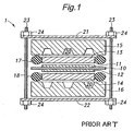
Figure 1 shows a conventional embodiment of a fuel cell assembly. As shown, thisfuel cell assembly 1 comprises anelectrolyte layer 10, a pair ofcatalyst electrode layers electrolyte layer 10, a pair ofdiffusion layers catalyst electrode layers diffusion layers separators diffusion layers diffusion layers electrolyte layer 10 as well as to contact thecatalyst electrode layers electrode layers separators separators seal members electrolyte layer 10 and theseparators diffusion layers - The
fuel cell assembly 1 is formed by stacking these component parts and applying a tightening force on them in the stacking direction so that the adjacent component parts are closely pressed to each other. For this purpose, a pair ofbacking plates separators rods 23 extend through thebacking plates nuts 24 are engaged with threaded ends of therods 23 so that the rotation of thenuts 24 can produce the pressure in the stacking direction. A required tightening pressure can be varied for different combinations of component parts to be pressed together. However, it should be noted that because thediffusion layers diffusion layers separators diffusion layers separators separators diffusion layers separators diffusion layers separators - However, in order for the
diffusion layers separators separators diffusion layers backing plates 21,rods 23 and nuts 24). These factors can undesirably increase the weight, volume and manufacturing cost of thefuel cell assembly 1. - The electrolyte of the
electrolyte layer 10 may consist of a solid polymer electrolyte (SPE). However, the SPE can function as an ion conducting membrane only when impregnated with water, and the SPE when impregnated with water significantly increases its volume. The volume of the SPE can also change depending on the temperature. Such volume increase of the SPE can generate stress inside thefuel cell assembly 1. Therefore, when the externally applied tightening force is large, the pressure applied to the component parts may become excessively high, which can cause a problem such as breaking theseal members - Generally, in the
fuel cell assembly 1, it is preferable that thediffusion layers catalyst electrode layers diffusion layers catalyst electrode layers separators 15, 16). Further, so long as a favorable diffusion capacity is achieved,thinner diffusion layers fuel cell assembly 1. However, in theconventional diffusion layers - In view of such problems of the prior art, an object of at least the preferred embodiments of the present invention is to provide a fuel cell assembly that can eliminate the need for applying a large tightening pressure to the separators and the diffusion layers in the assembled state.
- A second object of at least the preferred embodiments of the present invention is to provide a fuel cell assembly comprising a diffusion layer having a reduced surface roughness to thereby decrease the contact resistance between the diffusion layer and its adjoining component part.
- A third object of at least the preferred embodiments of the present invention is to provide a fuel cell assembly comprising a diffusion layer having an increased conductivity.
- A fourth object of at least the preferred embodiments of the present invention is to provide a fuel cell assembly comprising a diffusion layer having a substantially smaller thickness than the conventional diffusion layer while maintaining a favorable diffusing function.
- A fifth object of at least the preferred embodiments of the present invention is to provide a separator-diffusion layer assembly suitable for use in such a fuel cell assembly and to provide a method for manufacturing such a separator-diffusion layer assembly.
- According to the present invention there is provided, a method for manufacturing a separator-diffusion layer assembly of a fuel cell assembly, comprising the steps of: forming a diffusion layer on a surface of a substrate consisting of an inorganic material, wherein said diffusion layer is for diffusing a fluid evenly over an electrolyte layer and for contacting a catalyst electrode layer to transmit an electrode potential of said catalyst electrode layer to outside, wherein the diffusion layer has an electroconductive film formed integrally with the substrate and is provided with a plurality of fluid paths extending through the diffusion layer in a direction of its thickness; and bringing an etchant into contact with the surface of the substrate through the fluid paths of the diffusion layer to form a recess in the surface of the substrate for allowing a fuel fluid or an oxidizing fluid to flow therethrough and thereby make a separator.
- Thus, by allowing the etchant to reach the surface of the substrate through the fluid paths formed in the diffusion layer, it is possible to process the substrate and form the recess defining a passage for the fuel fluid or oxidizing fluid without complicated machining. Preferably, the step of forming a diffusion layer comprises a step of forming the electroconductive film on the surface of the substrate by a process comprising physical vapor deposition (PVD), chemical vapor deposition (CVD), spin coating, sputtering or screen printing.
- By using such a film forming process used in a semiconductor or micromachine manufacture in forming the electroconductive film of the diffusion layer, it is possible to form a very thin electroconductive film, which contributes to minimizing the dimension (thickness) of the resulting fuel cell assembly. The reduced thickness of the fuel cell assembly is preferred particularly when a plurality of such fuel cell assemblies are stacked together to form a series connection because the thickness of the resulting fuel cell stack can be also minimized. Further, the diffusion layers can have a high electric conductivity when the electroconductive film thereof is made of a highly electroconductive material such as a metal or an alloy.
- Also preferably, the step of forming a diffusion layer may comprise the step of forming a plurality of openings in the electroconductive film, wherein the fluid paths of the diffusion layer comprise the plurality of openings formed in the electroconductive film, and the plurality of openings of the electroconductive film are arranged to form one or more lines of openings in such a manner that adjacent openings in each line of openings partially overlap each other in a direction of extension of the line of openings. Alternatively or in addition, the step of forming a diffusion layer may comprise the steps of: forming a structure reinforcement member between the substrate and the electroconductive film; and forming a plurality of openings in the structure reinforcement member, wherein the fluid paths of the diffusion layer comprise the plurality of openings formed in the structure reinforcement member, and the plurality of openings of the structure reinforcement member are arranged to form one or more lines of openings in such a manner that adjacent openings in each line of openings partially overlap each other in a direction of extension of the line of openings. In this way, it is possible to form a recess(s) extending along the line(s) of openings of the electroconductive film or of the structure reinforcement member can be readily formed in the substrate by etching.
- The method of the invention may be utilised in the manufacture of a fuel cell assembly, comprising: an electrolyte layer; a pair of catalyst electrode layers interposing the electrolyte layer therebetween; a pair of separators each having a first surface facing the electrolyte layer and a second surface opposite to the first surface, the first surface of each separator being provided with a recess through which a fuel fluid or an oxidizing fluid flows to contact an associated one of the catalyst electrode layers; and a pair of diffusion layers each being disposed between the first surface of an associated one of the separators and an associated one of the catalyst electrode layers, wherein each of the diffusion layers comprises an electroconductive film formed integrally with the associated separator so as to form a separator-diffusion layer assembly in cooperation with the associated separator, and wherein each diffusion layer is formed with a plurality of fluid paths extending therethrough in a direction of its thickness so as to be in flow communication with the recess of the associated separator and thereby diffuse the fluid flowing in the recess over a surface of the associated catalyst electrode layer.
- Thus, by integrally forming the diffusion layer on the separator to constitute a separator-diffusion layer assembly, it is possible to eliminate the need for applying a large pressure on the diffusion layer and the separator to achieve close contact therebetween, and therefore, the tightening pressure externally applied to the fuel cell assembly can be considerably reduced. This can reduce the mechanical strength required to the component parts of the fuel cell assembly to thereby decrease the manufacturing cost thereof. Further, the influence of the stress that may be caused by expansion of the electrolyte layer in operation can be moderated, which eliminates the need for controlling the tightening pressure and thus can simplify the operation. The integrated diffusion layer and the separator also result in a smaller number of component parts and assembly steps.
- Each separator preferably comprises a silicon substrate or a glass substrate. The silicon substrate or glass substrate for use in semiconductor manufacture or the like has a very low surface roughness, and the diffusion layer formed thereon can readily assume a very low surface roughness in its surface facing the catalyst electrode layer. This not only can reduce the contact resistance between the diffusion layer and the catalyst electrode layer, but also can maintain the contact resistance substantially constant irrespective of the tightening pressure.
- The plurality of fluid paths of each diffusion layer may comprise a plurality of openings formed in the electroconductive film of the diffusion layer over the recess of the associated separator. Alternatively, each diffusion layer may comprise a plurality of electroconductive films wherein each of the plurality of electroconductive films is formed with a plurality of openings in such a manner that the openings of each electroconductive film are in flow communication with the openings of its adjacent electroconductive film(s) to form the plurality of fluid paths of the diffusion layer. When the recess of each separator extends in a prescribed direction, it will be preferable if the plurality of openings of the electroconductive film associated with each separator are arranged in a direction of extension of the recess to form a line of openings in such a manner that adjacent openings in the line of openings partially overlap each other in a direction of extension of the line of openings. In this way, the recess extending along the direction of arrangement of the openings can be obtained without a complicated process by just etching a substrate made of an inorganic material such as silicon using the openings as etching windows.
- In order to enhance the mechanical strength of the diffusion layers, each diffusion layer may preferably comprise a structure reinforcement member disposed between the electroconductive film and the associated separator. In the case that each separator comprises a silicon substrate, the structure reinforcement member can consist of a silicon nitride layer or a silicon oxide layer. The plurality of fluid paths of each diffusion layer may comprise a plurality of openings formed in the structure reinforcement member of the diffusion layer. In other words, the openings in the structure reinforcement members can contribute to evenly diffusing the fuel fluid and oxidizing fluid over the surfaces of the catalyst electrode layers. When the recess of each separator extends in a prescribed direction, it will be preferable if the plurality of openings of the structure reinforcement member associated with each separator are arranged in a direction of extension of the recess to form a line of openings in such a manner that adjacent openings in the line of openings partially overlap each other in a direction of extension of the line of openings. In this way, the recess extending along the direction of arrangement of the openings can be obtained without a complicated process by just etching a substrate made of an inorganic material such as silicon using the openings as etching windows.
- The method of the invention may also be utilised to produce a separator-diffusion layer assembly for a fuel cell assembly, comprising: a separator having a first surface formed with a recess through which a fuel fluid or an oxidizing fluid flows and a second surface opposite to the first surface, and a diffusion layer provided on the first surface of the separator, wherein the diffusion layer comprises an electroconductive film formed integrally with the separator and is formed with a plurality of fluid paths extending through the diffusion layer in a direction of its thickness so as to be in flow communication with the recess of the separator and thereby diffuse the fluid in the recess on a side of a surface of the diffusion layer facing away from the first surface of the separator.
- Other and further objects, features and advantages of the invention will appear more fully from the following description.
- Preferred embodiments of the present invention will now be described by way of example only and with reference to the appended drawings, in which:
-
Figure 1 is a schematic cross-sectional view for showing a conventional embodiment of a fuel cell assembly -
Figure 2 is a schematic cross-sectional view for showing a preferred embodiment of a fuel cell assembly according to the present invention; -
Figure 3 is a partial plan view of the separator-diffusion layer assembly of the fuel cell assembly shown inFigure 2 ; -
Figure 4 is a schematic cross-sectional view of the separator-diffusion layer assembly for showing an example of connection between the diffusion layer and the external electrode in the fuel cell assembly ofFigure 2 ; -
Figure 5 is a schematic cross-sectional view for showing another embodiment of the separator-diffusion layer assembly according to the present invention; -
Figures 6a-6d are schematic partial cross-sectional views for showing a preferred method for manufacturing the separator-diffusion layer assembly of the fuel cell assembly shown inFigures 2-4 ; -
Figures 7a-7c are schematic partial cross-sectional views for showing a preferred method for manufacturing the separator-diffusion layer assembly of the fuel cell assembly shown inFigures 2-4 ; -
Figures 8a-8e are schematic partial cross-sectional views for showing a preferred method for manufacturing the separator-diffusion layer assembly of the fuel cell assembly shown inFigure 5 ; -
Figures 9a-9c are partial plan views for showing three electroconductive films in yet another embodiment of the separator-diffusion layer assembly according to the present invention; -
Figure 10a is a partial plan view showing the overlapping three electroconductive films shown inFigures 9a-9c , andFigure 10b is a cross-sectional view taken along the line Xb-Xb inFigure 10a ; -
Figures 11a-11e are schematic partial cross-sectional views for showing a preferred method for manufacturing the separator-diffusion layer assembly of the fuel cell assembly shown inFigures 9a-10b ; and -
Figures 12a-12d are schematic partial cross-sectional views for showing a preferred method for manufacturing the separator-diffusion layer assembly of the fuel cell assembly shown inFigures 9a-10b . -
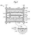
Figure 2 is a schematic cross-sectional view showing a preferred embodiment of a fuel cell assembly according to the present invention. Similar to theconventional fuel assembly 1, thisfuel cell assembly 100 comprises a centrally disposed electrolyte layer 110, a pair of catalyst electrode layers 111, 112 disposed on either side of the electrolyte layer 110, a pair ofseparators seal members separators backing plates rods 123 andnuts 124 for providing a tightening pressure when assembling together the component parts. Though not shown in the drawing, thefluid passages 120 are each provided with a fluid port(s) in its bottom for allowing entrance and discharge of the fluid into and out of thefluid passage 120. - This
fuel cell assembly 100 differs from the conventionalfuel cell assembly 1 ofFigure 1 in a sense that a pair ofdiffusion layers separators diffusion layer assemblies small openings 125 extending in a direction of thickness thereof so as to be in flow communication with thefluid passages 120 of the associatedseparators fluid passages 120 over the surface of the associated catalyst electrode layers 111,112. - As shown in a partial enlarged cross-sectional view in
Figure 2 , eachdiffusion layer structure reinforcement member 132 formed on the associatedseparator electroconductive film 133 formed on thestructure reinforcement member 132. When theseparators structure reinforcement member 132 can consist of a silicon nitride film or silicon oxide film deposited on the surface of theseparators electroconductive film 133 can be formed by a film forming process used in a semiconductor manufacturing or micromachine manufacturing processes such as physical vapor deposition (PVD), chemical vapor deposition (CVD), spin coating, etc. Thesmall openings 125 can be formed by patterning thestructure reinforcement member 132 andelectroconductive film 133 by etching, for example. -
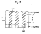
Figure 3 is a partial plan view showing a surface (first surface) of the separator-diffusion layer assembly 130 (131) that is formed with the diffusion layer 113 (114). In this drawing, the diffusion layer 113 (114) is shown with a part thereof broken away to show thefluid passages 120 in the separators 115 (116). As shown, theopenings 125 formed in the diffusion layer 113 (114) are arranged along the extension of thefluid passages 120 of the separator 115 (116). Eachopening 125 has an elongated shape and is inclined with respect to the direction of extension of thefluid passages 120 so that theopenings 125 adjoining in the direction of extension of thefluid passages 120 partially overlap each other. It should be noted thatFigure 2 shows a cross-section along the lines II-II inFigure 3 , and thus shows two partially overlappingopenings 125 over eachfluid passage 120. However, the number and position of theopenings 125 shown in the drawing may change depending on the position at which the cross-section is taken. Thus, by forming the plurality ofopenings 125 in the diffusion layer 113 (114) so that they are located over thefluid passages 120 to whereby supply the fuel fluid or oxidizing fluid in thefluid passages 120 to the catalyst electrode layer 111 (112) via theopenings 125, it is possible to diffuse the fluids evenly over the catalyst electrode layer 111 (112). Moreover, as describe later, theopenings 125 provided in the diffusion layer 113 (114) can be preferably used as etching windows when forming thefluid passages 120 in the separator 115 (116) by etching. - Similarly to the conventional embodiment, the
fuel cell assembly 100 shown inFigure 2 is formed by rotating the nuts 124 to thereby cause the adjoining component parts to closely contact with each other. However, because the diffusion layers 113, 114 and theseparators diffusion layer assemblies separators fuel cell assembly 100 can be substantially reduced. This can reduce the mechanical strength required to the component parts of thefuel cell assembly 100 to thereby decrease the manufacturing cost thereof. Further, the influence of the stress that may be caused by expansion of theelectrolyte layer 10 in operation can be moderated, which eliminates the need for controlling the tightening pressure and thus can simplify the operation. The integrated diffusion layers 113,114 and the separators 115,116 also result in a smaller number of component parts and assembly steps. - The
electroconductive film 133 and thestructure reinforcement member 132 can be formed by a film forming process used in semiconductor or micromachine manufacture, and therefore can be given a very small thickness, which in turn contributes to minimizing the size (thickness) of thefuel cell assembly 100. The reduced thickness of thefuel cell assembly 100 is preferred particularly when a plurality of suchfuel cell assemblies 100 are stacked together to form a series connection because the thickness of the resulting fuel cell stack can be also minimized. Theelectroconductive film 133 of the diffusion layers 113, 114 can have a high electric conductivity when it is made of a highly electroconductive material such as a metal or an alloy. - Further, when the
separators - As is well known in this art, the electric polarity of the
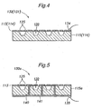
fuel cell assembly 100 is determined by the fluids supplied to thefluid passages 120. Specifically, the catalyst electrode layer 111, 112 (and the diffusion layer 113,114 contacting it) contacting the fuel fluid such as hydrogen (H2) constitutes an anode while catalyst electrode layer 111, 112 (and thediffusion layer Figure 4 ,external electrodes 134 may be attached to the diffusion layers 113, 114 directly. -
Figure 5 is a schematic cross-sectional view showing another embodiment of the separator-diffusion layer assembly according to the present invention. In this drawing, component parts similar to those inFigure 4 are denoted with the same numerals. In this separator-diffusion layer assembly 130a, aseparator 115a compriseselectroconductive paths 140 passing therethrough, and anelectroconductive film 141 is formed on a surface (outer or second surface) of theseparator 115a opposite to the surface (first surface) on that thediffusion layer 113 is formed. The diffusion layer 113 (more specifically, its electroconductive film 133) and theelectroconductive film 141 are connected to each other via the feedthroughconductive paths 140 whereby the electric potential of thediffusion layer 113 is transmitted to theelectroconductive film 141 on the outer surface of theseparator 115a. This can allow theexternal electrode 134 to be attached to theelectroconductive film 141 on the outer surface of theseparator 115a. When the fuel cell assembly utilizes the separator-diffusion layer assembly 130a ofFigure 5 , series-connection of a plurality of such fuel cell assemblies can be readily achieved by just making the separator outer surfaces of adjoining fuel cell assemblies contact each other. The mechanically and electricallyunified diffusion layer 113 andseparator 115a can remove concern about the contact resistance therebetween and can make the resistance constant irrespective of the degree of the tightening pressure. Further, the feedthroughconductive paths 140 each provides a shortest path connecting thediffusion layer 113 to theelectroconductive film 141 on the outer surface of theseparator 115a, to thereby contribute to minimizing the internal resistance of the fuel cell assembly. - Referring to
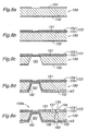
Figures 6a-7c , a preferred process for manufacturing the separator-diffusion layer assembly 130 (131) having the integrally formed separator 115 (116) and diffusion layer 113 (114) as shown inFigures 2-4 is described hereinafter. - First, as shown in
Figure 6a , asubstrate 150 consisting of single crystal silicon and having a thickness of about 400 µ m, for instance, is washed by using sulfuric acid or the like, and then, as shown inFigure 6b ,silicon nitride films substrate 150 by sputtering. - Then, as shown in
Figure 6c , anelectroconductive film 153 of about 2 µm thickness is formed on top of thesubstrate 150 by physical vapor deposition (PVD), for example. Theelectroconductive film 153 can preferably have a two-layered structure comprising a titanium (Ti)layer 155 having a thickness of about 0.1 µm and a gold (Au)layer 154 of about 2 µm formed thereon. Titanium improves the contact between the silicon nitride and gold, and may be substituted by aluminum (Al), nickel (Ni) or chromium (Cr). Gold may be substituted by other electroconductive material such as nickel (Ni), copper (Cu), platinum (Pt), iron (Fe), tungsten (W), molybdenum (Mo), doped silicon or polysilicon. Also, film forming processes other than the physical vapor deposition, such as chemical vapor deposition (CVD), spin coating, sputtering or screen printing may be used. - In the next step, as shown in
Figure 6d , etching is performed on theelectroconductive film 153 to form a plurality ofopenings 156. Similarly to theopenings 125 shown inFigure 3 , in order to form a plurality of parallel-extending fluid passages 159 (Figure 7c ) in thesubstrate 150, theopenings 156 are arranged along a direction of extension of each fluid passage 159 (a direction vertical to the sheet ofFigure 6d ) to form lines ofopenings 156. Theopenings 156 each have an elongated shape and are inclined with respect to the direction of arrangement of thereof so that in each line ofopenings 156, adjoiningopenings 156 overlap each other in the direction of arrangement. In the cross-sectional view ofFigure 6d , twoopenings 156 overlapping each other in the direction of arrangement are shown in a similar fashion as inFigure 2 . - Subsequently, as shown in
Figure 7a , reactive ion etching (RIE) using CF4 is conducted with a mask (not shown) to form a plurality ofsmall openings 157 in thesilicon nitride film 151 on the top surface of thesubstrate 150 at positions aligned with theopenings 156 of theelectroconductive film 153. Theopenings 157 can serve as etching windows for forming the fluid passages 159 (Figure 7c ). Similarly to theopenings 156 of theelectroconductive film 153, theopenings 157 each have an elongated shape and are inclined with respect to the direction of arrangement thereof so that in each line ofopenings 157, the ends of the adjoiningopenings 157 overlap each other in the direction of arrangement. - Further, as shown in
Figure 7b , similar etching is performed with a mask (not shown) to remove portions of thesilicon nitride film 152 on the underside of thesubstrate 150 where fluid ports 160 (Figure 7c ) for allowing entrance and discharge to and from thefluid passages 159 provided in thesubstrate 150 are to be formed. - Finally as shown in
Figure 7c , thesubstrate 150 is wet etched using an alkali solution such as KOH solution to whereby form thefluid passages 159 andfluid ports 160. Since this process is anisotropic etching, the side wall of eachfluid passage 159 andfluid port 160 inclines at an angle reflecting the crystal orientation of the silicon. It should be noted that because theopenings 157 of thesilicon nitride film 151 on the top surface of thesubstrate 150 are arranged in a direction of extension of thefluid passages 159 and theopenings 157 adjoining in the direction of arrangement partly overlap each other, acontinuous fluid passage 159 can be preferably formed under each line ofopenings 157. Thus, the separator-diffusion layer assembly 130 (131) as shown inFigures 2-4 is obtained. As will be understood, theopenings Figure 7c correspond to theopenings 125 inFigures 2-4 . Also, the uppersilicon nitride film 151 functions as thestructure reinforcement member 132 shown in the enlarged view inFigure 2 . - Next, with reference to
Figures 8a-8e , a preferred process for manufacturing the separator-diffusion layer assembly 130a having the feedthroughconductive paths 140 is described hereinafter. In these drawings, portions similar to those inFigures 6a-7c are denoted with the same numeral and detailed explanation thereof is omitted. - After forming the
silicon nitride films silicon substrate 150 in the step ofFigure 6b , etching is conducted with a mask (not shown) to remove portions of thesilicon nitride film 151 on top of thesubstrate 150 where feedthrough conductive paths 162 (Figure 8d ) are to be formed, as shown inFigure 8a . - Then, in the step shown in
Figure 8b , theelectroconductive film 153 is formed on top of thesubstrate 150 by vapor deposition, spin coating or the like. As in the above embodiment, theelectroconductive film 153 preferably has a two-layered structure comprising thegold layer 154 and thetitanium layer 155. - Next, after etching is performed with a mask (not shown) to remove portions of the
silicon nitride film 152 on the underside of thesubstrate 150 where the feedthrough conductive paths 162 (Figure 8d ) are to be formed, wet etching is performed with an alkali solution such as KOH solution to form throughholes 161 reaching theelectroconductive film 153 covering the top surface of thesilicon substrate 150. Since this process is also anisotropic etching, the side wall of each through-hole 161 inclines at an angle reflecting the crystal orientation of the silicon such that the cross-section of each through-hole 161 diverges from the top to under surface of the substrate 150 (or from the first to second surface of theseparator 115a). - Subsequently, as shown in
Figure 8d , metallic material is deposited from underside the substrate by vapor deposition or the like to formelectroconductive films substrate 150 and a gold layer adjoining the titanium layer, on the side wall of the through-holes 161 and on the under surface of thesubstrate 150, respectively. The metallic material is also deposited on the underside of theelectroconductive film 153 covering the upper opening of the through-holes 161, and thus theelectroconductive film 153 and theelectroconductive film 162 on the side wall of the through-holes 161 are connected to each other. It should be noted that since the side wall of each through-hole 161 is inclined as described above, the deposition of the metallic material thereon is facilitated so that the sufficiently thick anduniform electroconductive film 162 on the side wall can be preferably achieved. It should be also noted that in the step shown inFigure 8c , dry etching or other process may be used instead of wet etching to form the through-holes 161 having a vertical side wall. In such a case, however, forming theelectroconductive film 162 uniformly on the side wall could become more difficult than in the case where the through-holes 161 are formed by wet etching. - Thus, the
electroconductive film 162 on the side wall of each through-hole 161 connects theelectroconductive film 153 on top of thesubstrate 150 and theelectroconductive film 163 on the underside of the same. In other words, theelectroconductive film 162 on the side wall of each through-hole 161 functions as the feedthroughconductive path 140 shown inFigure 5 . Thereafter, the steps shown inFigures 6d-7c are carried out similarly, whereby thefluid passages 159,fluid ports 160, etc. are formed as shown inFigure 8e , providing the separator-diffusion layer assembly 130a having the feedthrough conductive path 140 (electroconductive film 162) as shown inFigure 5 . - In the above embodiments, the diffusion layer 113 (114) has only a single electroconductive film 133 (153) formed with the openings 125 (156). However, it is possible to stack a plurality of patterned electroconductive films to provide a diffusion layer with complicated fluid paths that can achieve more even diffusion of the fluids. For example, it is possible to form second and third electro
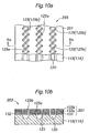
conductive films electroconductive film 133 of the separator-diffusion layer assembly 130 (131) shown inFigure 2 to provide a separator-diffusion layer assembly 203 comprising adiffusion layer 201 having threeelectroconductive films -
Figures 9a-9c show an example of patterning of theelectroconductive films Figure 9a is substantially the same asFigure 3 and shows the shape and arrangement of theopenings 125 of theelectroconductive film 133 together with thefluid passages 120 of the separator 115 (116). As shown inFigure 9b , in this embodiment, thesecond electroconductive film 133a comprisesopenings 125a of which inclination angle with respect to the direction of extension of thefluid passage 120 is different from that of theopenings 125 of thefirst electroconductive film 133, while as shown inFigure 9c , thethird electroconductive film 133b is formed withopenings 125b in the same shape and arrangement as theopenings 125 of thefirst electroconductive film 133. -
Figure 10a is a plan view showing theelectroconductive films Figure 10b shows a cross-sectional view taken along the line Xb-Xb inFigure 10a . As seen in these drawings, theopenings 125 of thefirst electroconductive film 133 are in flow communication with theopenings 125b of thethird electroconductive film 133b via theopenings 125a of thesecond electroconductive film 133a to whereby form fluid paths extending through the thickness of thediffusion layer 201. Eachopening 125a of thesecond electroconductive film 133a is in flow communication with a plurality ofopenings 125 of thefirst electroconductive film 133 and with a plurality ofopenings 125b of thethird electroconductive film 133b so that the fluid paths assume a complicated labyrinth structure, and thus the fuel fluid or oxidizing fluid in therecess 120 of the separator 115 (116) is favorably diffused over the catalyst electrode layer 111 (112) through the fluid paths. - In the following, with reference to the schematic drawings of
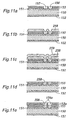
Figures 11a-11e andFigures 12a-12d , a preferred method of manufacturing the above shown separator-diffusion layer assembly 203 having a multiple electroconductive films is described. In these drawings, portions corresponding to those inFigures 6a-7c are denoted with same numerals. - First, according to the steps described above with reference to
Figures 6a-7a , thesilicon nitride films silicon substrate 150, the electroconductive film (first electroconductive film) 153 containing thegold layer 154 andtitanium layer 155 is formed on top thereof, and thefirst electroconductive film 153 and thesilicon nitride film 151 are patterned by etching or the like to form a plurality ofopenings Figure 11a . - In a step shown in
Figure 11b , asacrifice layer 258 consisting of silicon oxide (SiO2), for example, is formed to fill in theopenings 157 of the uppersilicon nitride film 151 and theopenings 156 of thefirst electroconductive film 153 with thesacrifice layer 258. - Further, after forming a resist 259 on the
sacrifice layer 258 as shown inFigure 11c , the resist 259 and thesacrifice layer 258 are etched by dry etching until the top surface of thefirst electroconductive film 153 is exposed, to thereby flatten the top surface. - Then, by using the steps as described above, a
second electroconductive film 153a is formed on the flattened top surface, and patterned to form a plurality ofopenings 156a, as shown inFigure 11e . Further, by the steps similar to those shown inFigures 11b-11d , theopenings 156a of thesecond electroconductive film 153a is filled with asacrifice layer 258a, a resist (not shown) is formed thereon, and etching is conducted to flatten the top surface (Figure 12a ). - Further, after a
third electroconductive film 153b is formed and patterned to formopenings 156b by again using the above-described steps, etching is performed to remove thesacrifice layer 258 filling in theopenings 157 of thesilicon nitride film 151 and theopenings 156 of thefirst electroconductive film 153 as well as thesacrifice layer 258a filling in theopenings 156a of thesecond electroconductive film 153a, as shown inFigure 12b . This brings theopenings electroconductive films openings 157 of thesilicon nitride film 151 into flow communication so that the flow paths extending through thediffusion layer 201 is formed. - Finally, as shown in
Figure 12d , thesilicon substrate 150 is wet etched by using a KOH solution to form thefluid passages 159 andfluid ports 160, to thereby obtain the unitary separator-diffusion layer assembly 203. In this step, the etchant can reach the surface of thesilicon substrate 150 through theopenings electroconductive films openings 157 of thesilicon nitride film 151 that form the fluid paths extending through thediffusion layer 201. Thus, the etching of thesubstrate 150 can be favorably carried out even with the unitarily formeddiffusion layer 201. - Although the present invention has been described in terms of preferred embodiments thereof, it is obvious to a person skilled in the art that various alterations and modifications are possible without departing from the scope of the present invention which is set forth in the appended claims. For instance, though in the above embodiments the deposited electroconductive film is patterned by etching, an electroconductive film having a predetermined pattern can be also obtained by photolithography, lift-off, etc. Also, in the above embodiments, the electroconductive film and the structure reinforcement member of the diffusion layer formed integrally with the separator are provided with a plurality of openings arranged along each fluid passage (recess) of the separator such that the opening each have an elongated shape and are inclined with respect to the direction of arrangement thereof. However, the shape of the opening can vary in a variety of ways, and may have a V-shape or W-shape, for example. In such cases also, it is preferred that the openings adjoining in the direction of arrangement partially overlap each other because fluid passages extending along the direction of arrangement of the openings can be readily obtained by etching the separator using such openings as etching windows.
- As described above, according to the present invention, the diffusion layer of the fuel cell assembly comprises an electroconductive film integrally formed with the separator so that the separator and the diffusion layer constitute a unitary separator-diffusion layer assembly. This can eliminate the need for applying a large external pressure for making the separator and the diffusion layer closely contact with each other. This also reduces the pressure applied on other component parts in the fuel cell assembly, decreasing the required mechanical strength and the manufacturing cost. The integrated diffusion layer and the separator also reduce the number of component parts and manufacturing steps. Further, by forming the electroconductive film using a film forming process used in a semiconductor or micromachine manufacture, it is possible to achieve a very thin diffusion layer comprising the electroconductive film, which contributes to minimizing the dimension (thickness) of the resulting fuel cell assembly.
Claims (4)
- A method for manufacturing a separator-diffusion layer assembly of a fuel cell assembly, comprising the steps of:forming a diffusion layer (113,114,201) on a surface of a substrate (150) consisting of an inorganic material, wherein said diffusion layer is for diffusing a fluid evenly over an electrolyte layer (110) and for contacting a catalyst electrode layer (111,112) to transmit an electrode potential of said catalyst electrode layer to outside, wherein said diffusion layer has an electroconductive film (133,133a,133b) formed integrally with said substrate and is provided with a plurality of fluid paths (125,125a,125b) extending through said diffusion layer in a direction of its thickness; andbringing an etchant into contact with said surface of said substrate through said fluid paths of said diffusion layer to form a recess (120) in said surface of said substrate for allowing a fuel fluid or an oxidizing fluid to flow therethrough and thereby make a separator (115,116,115a).
- A method according to claim 1, wherein said step of forming a diffusion layer (113,114,201) comprises a step of forming said electroconductive film (133,133a,133b) on said surface of said substrate (150) by a process comprising physical vapor deposition (PVD), chemical vapor deposition (CVD), spin coating, sputtering or screen printing.
- A method according to claim 1 or 2, wherein said step of forming a diffusion layer (113,114,201) comprises the step of forming a plurality of openings (125) in said electroconductive film (133,133a,133b), wherein said fluid paths of said diffusion layer comprise said plurality of openings formed in said electroconductive film, and said plurality of openings of said electroconductive film are arranged to form one or more lines of openings in such a manner that adjacent openings in each line of openings partially overlap each other in a direction of extension of said line of openings.
- A method according to claim 1, 2 or 3, wherein said step of forming a diffusion layer (113,114,201) comprises the steps of:forming a structure reinforcement member (132) between said substrate (150) and said electroconductive film (133,133a,133b); andforming a plurality of openings in said structure reinforcement member,wherein said fluid paths of said diffusion layer comprise said plurality of openings formed in said structure reinforcement member, and said plurality of openings of said structure reinforcement member are arranged to form one or more lines of openings in such a manner that adjacent openings in each line of openings partially overlap each other in a direction of extension of said line of openings.
Applications Claiming Priority (2)
| Application Number | Priority Date | Filing Date | Title |
|---|---|---|---|
| US37952402P | 2002-05-09 | 2002-05-09 | |
| EP03728026A EP1525638A2 (en) | 2002-05-09 | 2003-05-02 | Fuel cell assembly, separator-diffusion layer assembly for fuel cell assembly and manufacturing method therefor |
Related Parent Applications (1)
| Application Number | Title | Priority Date | Filing Date |
|---|---|---|---|
| EP03728026A Division EP1525638A2 (en) | 2002-05-09 | 2003-05-02 | Fuel cell assembly, separator-diffusion layer assembly for fuel cell assembly and manufacturing method therefor |
Publications (2)
| Publication Number | Publication Date |
|---|---|
| EP1643577A1 EP1643577A1 (en) | 2006-04-05 |
| EP1643577B1 true EP1643577B1 (en) | 2008-10-22 |
Family
ID=35986127
Family Applications (1)
| Application Number | Title | Priority Date | Filing Date |
|---|---|---|---|
| EP05013990A Expired - Fee Related EP1643577B1 (en) | 2002-05-09 | 2003-05-02 | Fuel cell assembly, separator-diffusion layer assembly for fuel cell assembly and manufacturing method therefor |
Country Status (1)
| Country | Link |
|---|---|
| EP (1) | EP1643577B1 (en) |
Families Citing this family (1)
| Publication number | Priority date | Publication date | Assignee | Title |
|---|---|---|---|---|
| CN102742057B (en) * | 2008-03-11 | 2016-06-01 | 松下知识产权经营株式会社 | Membrane-electrode assembly |
Family Cites Families (3)
| Publication number | Priority date | Publication date | Assignee | Title |
|---|---|---|---|---|
| JP3904696B2 (en) * | 1997-11-11 | 2007-04-11 | 日新製鋼株式会社 | Low temperature fuel cell separator and method for producing the same |
| AU3263001A (en) * | 1999-11-17 | 2001-05-30 | Neah Power Systems, Inc. | Fuel cells having silicon substrates and/or sol-gel derived support structures |
| US6924058B2 (en) * | 1999-11-17 | 2005-08-02 | Leroy J. Ohlsen | Hydrodynamic transport and flow channel passageways associated with fuel cell electrode structures and fuel cell electrode stack assemblies |
-
2003
- 2003-05-02 EP EP05013990A patent/EP1643577B1/en not_active Expired - Fee Related
Also Published As
| Publication number | Publication date |
|---|---|
| EP1643577A1 (en) | 2006-04-05 |
Similar Documents
| Publication | Publication Date | Title |
|---|---|---|
| CA2484294C (en) | Fuel cell assembly, separator-diffusion layer assembly for fuel cell assembly and manufacturing method therefor | |
| EP1316118A2 (en) | Fuel cell assembly and method for making the same | |
| US7153602B2 (en) | Fuel cell assembly | |
| US20040115507A1 (en) | Monolithic fuel cell and method of manufacture | |
| US8003275B2 (en) | Monopolar membrane-electrode assembly | |
| Min et al. | Fabrication of novel MEMS-based polymer electrolyte fuel cell architectures with catalytic electrodes supported on porous SiO2 | |
| JP2005517273A (en) | High power density fuel cell layer device using microstructured components | |
| JP2002141084A (en) | Fuel cell | |
| EP1643577B1 (en) | Fuel cell assembly, separator-diffusion layer assembly for fuel cell assembly and manufacturing method therefor | |
| US7235323B2 (en) | Fuel cell assembly and method for making the same | |
| JP2003282089A (en) | Micro fuel cell | |
| JP7324304B2 (en) | FUEL BATTERY CELL, FUEL BATTERY CELL MANUFACTURING METHOD | |
| JP4214674B2 (en) | Fuel cell separator | |
| WO2021050997A2 (en) | Electrode tabs and methods of forming | |
| JP2004207155A (en) | Fuel cell and manufacturing method thereof | |
| JP2002329506A (en) | Cell plate for fuel cell, its manufacturing method and fuel cell stack | |
| JP2024018349A (en) | Channel members, electrochemical cells and electrochemical cell devices | |
| JP5826841B2 (en) | Fuel cell comprising a plurality of basic cells connected in series and method for manufacturing the same | |
| JP2001035504A (en) | Solid high polymer type fuel cell and manufacture of separator for the same |
Legal Events
| Date | Code | Title | Description |
|---|---|---|---|
| PUAI | Public reference made under article 153(3) epc to a published international application that has entered the european phase |
Free format text: ORIGINAL CODE: 0009012 |
|
| AC | Divisional application: reference to earlier application |
Ref document number: 1525638 Country of ref document: EP Kind code of ref document: P |
|
| AK | Designated contracting states |
Kind code of ref document: A1 Designated state(s): DE FR GB IT |
|
| RTI1 | Title (correction) |
Free format text: FUEL CELL ASSEMBLY, SEPARATOR-DIFFUSION LAYER ASSEMBLY FOR FUEL CELL ASSEMBLY AND MANUFACTURING METHOD THEREFOR |
|
| 17P | Request for examination filed |
Effective date: 20060531 |
|
| 17Q | First examination report despatched |
Effective date: 20060724 |
|
| AKX | Designation fees paid |
Designated state(s): DE FR GB IT |
|
| GRAP | Despatch of communication of intention to grant a patent |
Free format text: ORIGINAL CODE: EPIDOSNIGR1 |
|
| GRAS | Grant fee paid |
Free format text: ORIGINAL CODE: EPIDOSNIGR3 |
|
| GRAA | (expected) grant |
Free format text: ORIGINAL CODE: 0009210 |
|
| AC | Divisional application: reference to earlier application |
Ref document number: 1525638 Country of ref document: EP Kind code of ref document: P |
|
| AK | Designated contracting states |
Kind code of ref document: B1 Designated state(s): DE FR GB IT |
|
| REG | Reference to a national code |
Ref country code: GB Ref legal event code: FG4D |
|
| REF | Corresponds to: |
Ref document number: 60324336 Country of ref document: DE Date of ref document: 20081204 Kind code of ref document: P |
|
| PLBE | No opposition filed within time limit |
Free format text: ORIGINAL CODE: 0009261 |
|
| STAA | Information on the status of an ep patent application or granted ep patent |
Free format text: STATUS: NO OPPOSITION FILED WITHIN TIME LIMIT |
|
| PG25 | Lapsed in a contracting state [announced via postgrant information from national office to epo] |
Ref country code: IT Free format text: LAPSE BECAUSE OF FAILURE TO SUBMIT A TRANSLATION OF THE DESCRIPTION OR TO PAY THE FEE WITHIN THE PRESCRIBED TIME-LIMIT Effective date: 20081022 |
|
| PGFP | Annual fee paid to national office [announced via postgrant information from national office to epo] |
Ref country code: DE Payment date: 20090520 Year of fee payment: 7 Ref country code: FR Payment date: 20090523 Year of fee payment: 7 |
|
| 26N | No opposition filed |
Effective date: 20090723 |
|
| PGFP | Annual fee paid to national office [announced via postgrant information from national office to epo] |
Ref country code: GB Payment date: 20090422 Year of fee payment: 7 |
|
| GBPC | Gb: european patent ceased through non-payment of renewal fee |
Effective date: 20100502 |
|
| REG | Reference to a national code |
Ref country code: FR Ref legal event code: ST Effective date: 20110131 |
|
| PG25 | Lapsed in a contracting state [announced via postgrant information from national office to epo] |
Ref country code: DE Free format text: LAPSE BECAUSE OF NON-PAYMENT OF DUE FEES Effective date: 20101201 |
|
| PG25 | Lapsed in a contracting state [announced via postgrant information from national office to epo] |
Ref country code: FR Free format text: LAPSE BECAUSE OF NON-PAYMENT OF DUE FEES Effective date: 20100531 |
|
| PG25 | Lapsed in a contracting state [announced via postgrant information from national office to epo] |
Ref country code: GB Free format text: LAPSE BECAUSE OF NON-PAYMENT OF DUE FEES Effective date: 20100502 |