EP1643319A1 - Control of fixing unit with two heater connected in series - Google Patents
Control of fixing unit with two heater connected in series Download PDFInfo
- Publication number
- EP1643319A1 EP1643319A1 EP05021427A EP05021427A EP1643319A1 EP 1643319 A1 EP1643319 A1 EP 1643319A1 EP 05021427 A EP05021427 A EP 05021427A EP 05021427 A EP05021427 A EP 05021427A EP 1643319 A1 EP1643319 A1 EP 1643319A1
- Authority
- EP
- European Patent Office
- Prior art keywords
- heater
- state
- electric current
- temperature
- fixing unit
- Prior art date
- Legal status (The legal status is an assumption and is not a legal conclusion. Google has not performed a legal analysis and makes no representation as to the accuracy of the status listed.)
- Granted
Links
- 238000010438 heat treatment Methods 0.000 claims abstract description 32
- 230000004044 response Effects 0.000 claims description 12
- 230000008859 change Effects 0.000 claims description 5
- 238000012546 transfer Methods 0.000 description 33
- 238000004140 cleaning Methods 0.000 description 8
- 238000000034 method Methods 0.000 description 8
- 238000010276 construction Methods 0.000 description 6
- 230000008569 process Effects 0.000 description 6
- 230000009467 reduction Effects 0.000 description 5
- 239000003086 colorant Substances 0.000 description 3
- 230000001186 cumulative effect Effects 0.000 description 3
- 230000000694 effects Effects 0.000 description 3
- 230000005611 electricity Effects 0.000 description 3
- 230000007704 transition Effects 0.000 description 3
- 230000000052 comparative effect Effects 0.000 description 2
- 238000010586 diagram Methods 0.000 description 2
- 238000009826 distribution Methods 0.000 description 2
- 238000004904 shortening Methods 0.000 description 2
- 238000009833 condensation Methods 0.000 description 1
- 230000005494 condensation Effects 0.000 description 1
- 238000001514 detection method Methods 0.000 description 1
- 238000011156 evaluation Methods 0.000 description 1
- 239000004744 fabric Substances 0.000 description 1
- 230000001678 irradiating effect Effects 0.000 description 1
- 239000000463 material Substances 0.000 description 1
- 238000005259 measurement Methods 0.000 description 1
- 238000012986 modification Methods 0.000 description 1
- 230000004048 modification Effects 0.000 description 1
- 238000013021 overheating Methods 0.000 description 1
- 238000002360 preparation method Methods 0.000 description 1
- 238000003825 pressing Methods 0.000 description 1
- 238000012545 processing Methods 0.000 description 1
- 239000007787 solid Substances 0.000 description 1
- 230000037303 wrinkles Effects 0.000 description 1
Images




Classifications
-
- G—PHYSICS
- G03—PHOTOGRAPHY; CINEMATOGRAPHY; ANALOGOUS TECHNIQUES USING WAVES OTHER THAN OPTICAL WAVES; ELECTROGRAPHY; HOLOGRAPHY
- G03G—ELECTROGRAPHY; ELECTROPHOTOGRAPHY; MAGNETOGRAPHY
- G03G15/00—Apparatus for electrographic processes using a charge pattern
- G03G15/20—Apparatus for electrographic processes using a charge pattern for fixing, e.g. by using heat
- G03G15/2003—Apparatus for electrographic processes using a charge pattern for fixing, e.g. by using heat using heat
- G03G15/2014—Apparatus for electrographic processes using a charge pattern for fixing, e.g. by using heat using heat using contact heat
- G03G15/2039—Apparatus for electrographic processes using a charge pattern for fixing, e.g. by using heat using heat using contact heat with means for controlling the fixing temperature
- G03G15/205—Apparatus for electrographic processes using a charge pattern for fixing, e.g. by using heat using heat using contact heat with means for controlling the fixing temperature specially for the mode of operation, e.g. standby, warming-up, error
-
- G—PHYSICS
- G03—PHOTOGRAPHY; CINEMATOGRAPHY; ANALOGOUS TECHNIQUES USING WAVES OTHER THAN OPTICAL WAVES; ELECTROGRAPHY; HOLOGRAPHY
- G03G—ELECTROGRAPHY; ELECTROPHOTOGRAPHY; MAGNETOGRAPHY
- G03G2215/00—Apparatus for electrophotographic processes
- G03G2215/20—Details of the fixing device or porcess
Definitions
- the present invention is directed to a fixing unit and an image forming apparatus equipped with the fixing unit.
- an image forming apparatus such as a printer, a copying machine, a fax machine or the like which uses electronic photography is provided with a fixing apparatus.
- the fixing apparatus is provided for heating a recording medium such as paper or the like which carries a toner image formed from toner in an unfixed state as well as for applying pressure thereto to fix the toner image onto the recording medium (see JP-A No. 2004-262976).
- Such a fixing unit includes a pair of cylindrical rollers (rotating bodies) which are rotated with being presse d to each other, and a heat source which heats at least one of these rollers.
- a pair of cylindrical rollers rotating bodies
- a heat source which heats at least one of these rollers.
- the heater tends to consume a greater amount of electricity for the sake of, e.g., shortening a warm-up time.
- the heater with increased electricity consumption has a small resistance, which involves a problem in that a surge current may flow therethrough to thereby generate what is called a "flicker" phenomenon at the time when the connection to an electric power source is switched from an off-state to an on-state.
- this problem becomes conspicuous at the time when the heater remains at a lower temperature, because the resistance of the heater is also kept small at this time.
- a heater (second heater) is used as the resistor in the Japanese publication cited above. This makes it possible to avoid any occurrence of flicker and, in addition, to efficiently employ the heat energy generated by the heater in heating the afore-mentioned rotating bodies or other components.
- the present invention is directed to a fixing unit for use in passing a recording medium carrying a unfixed image through between a pair of rotating bodies which are rotated with being pressed to each other to heat and press the recording medium thereby filing the unfixed image to the recording medium, comprising: a first heater for generating heat energy with electric current supplied from a power source to heat up one of the rotating bodies; a second heater for generating heat energy with the electric current supplied from the power source to heat up the one of the rotating bodies or other components; and a switching means for changing over a first state that the first heater and the second heater are serially connected to and supplied with the electric current from the power source and a second state that the first heater is connected to and supplied with the electric current from the power source while the second heater is substantially disconnected from the power source, wherein the relation: Q 11 /Q 21 >1/8 is satisfied, where Q 11 denotes a heating value of the first heater in the first state per unit of time and Q 21 denotes a heating value of the first heater
- the fixing unit can avoid any occurrence of flicker and exhibit an excellent fixing ability.
- the switching means is adapted to change over the first state and the second state based on a history of electric current supply to the first heater.
- the switching means is adapted to take the first state in the case where no electric current was supplied to the first heater within a predetermined time period in advance of restarting the electric current supply, but take the second state in the case where the electric current was supplied to the first heater within the predetermined time period.
- the second heater is adapted to heat up the other of the rotating bodies.
- the fixing unit further comprises a first temperature detector means for detecting a temperature of one of the rotating bodies, a second temperature detector means for detecting a temperature of the other components and a control means for controlling an amount of the electric current supplied from the power source to the first heater and the second heater per unit of time in response to the temperature detected by the first temperature detector means and the second temperature detector means, wherein the second heater is adapted to heat up the other of the rotating bodies and wherein the control means is adapted, in the first state, to control the amount of the electric current supplied from the power source to the first heater and the second heater per unit of time in response to the temperature detected by the second temperature detector means and, in the second state, to control the amount of the electric current supplied from the power source to the first heater per unit of time in response to the temperature detected by the first temperature detector means.
- Q 21 >Q T1 >Q 11 , Q 12 >Q T2 and Q 21 x(1-Q T2 / Q 12 )+Q 11 xQ T2 / Q 12 >Q T1 are satisfied, where Q 12 denotes a heating value of the second heater in the first state per unit of time, Q T1 denotes a heating value required to maintain the one of the rotating bodies heated by the first heater at a first target temperature per unit of time, and Q T2 denotes a heating value required to maintain the other of the rotating bodies or the other components heated by the second heater at a second target temperature lower than the first target temperature per unit of time.
- the switching means is adapted to primarily take the second state when the one of the rotating bodies is heated up to the first target temperature, but mainly take the first state when the other components are heated up to the second target temperature lower than the first target temperature.
- the switching means comprises a first switch element for connecting the first heater and the second heater to the power source in series and a second switch element for short-circuiting the second heater and at the same time connecting the first heater to the power source, wherein the first state is taken by turning on the first switch element and the second state is taken by turning on the second switch element.
- an image forming apparatus which incorporates the fixing unit described above.
- FIG. 1 is a schematic cross-sectional view of the overall construction which shows one embodiment of an image forming apparatus in accordance with the present invention.
- FIG. 2 is a schematic cross-sectional view which illustrates a preferred embodiment of a fixing unit employed in the image forming apparatus shown in FIG. 1.
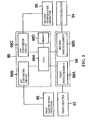
- FIG. 3 is a block diagram which shows a heater control system of the fixing unit illustrated in FIG. 2.
- FIG. 4 is a schematic view which illustrates a heater drive circuit of the fixing unit illustrated in FIG. 2. ,
- FIG. 5 is a flowchart for explaining a heater drive control operation in the fixing unit illustrated in FIG. 2.
- FIG. 6 is a flowchart for explaining a heat drive control operation in the fixing unit illustrated in FIG. 2.
- FIG. 7 is a view which shows the temperature transition of a fixing roller and a pressure roller in the fixing unit illustrated in FIG. 2.
- FIGS. 1 through 7 preferred embodiments of a fixing unit and an image forming apparatus equipped with the fixing unit in accordance with the present invention will be described with reference to FIGS. 1 through 7.
- FIG. 1 is a schematic cross-sectional view of the overall construction which shows one embodiment of an image forming apparatus in accordance with the present invention
- FIG. 2 is a schematic cross-sectional view which illustrates a preferred embodiment of a fixing unit employed in the image forming apparatus shown in FIG. 1
- FIG. 3 is a block diagram which shows a heater control system of the fixing unit illustrated in FIG. 2
- FIG. 4 is a schematic view which illustrates a heater drive circuit of the fixing unit illustrated in FIG. 2
- FIG. 5 is a flowchart for explaining a heater drive control operation in the fixing unit illustrated in FIG. 2
- FIG. 6 is a flowchart for explaining a heat drive control operation in the fixing unit illustrated in FIG. 2
- FIG. 7 is a view which shows the temperature transition of a fixing roller and a pressure roller in the fixing unit illustrated in FIG. 2.
- the image forming apparatus 10 of this embodiment is provided with a photosensitive body 20 that carries latent images and rotates in the direction of arrow.
- the image forming apparatus 10 further includes a charging unit 30, an exposure unit 40, a developing unit 50, a primary transfer unit 60 and a cleaning unit 75 in the named sequence, and they are arranged in that order along the rotational direction of the photosensitive body 20.
- the image forming apparatus 10 is provided, at the lower part in FIG. 1, with a paper supply tray 82 that serves to feed a recording medium P such as a paper.
- a secondary transfer unit 80 and a fixing unit 90 are sequentially disposed with respect to the paper supply tray 82 at the downstream of the conveying direction of the recording medium P.
- the photosensitive body 20 has a cylindrical conductive base material (not shown in the drawings) and a photosensitive layer (not shown) formed on the circumference thereof.
- the photosensitive body 20 is rotatable about its axis in the direction indicated with the arrow in FIG. 1.
- the charging unit 30 is a device for uniformly charging the surface of the photosensitive body 20 by means of corona charging and the like.
- the exposure unit 40 is a device which forms an electrostatic latent image by receiving image information from a host computer such as a personal computer not shown in the drawings, and in response to the image information received, irradiating a laser beam onto the uniformly charged photosensitive body 20.
- the developing unit 50 includes four developing devices, i.e., a black developing device 51, a magenta developing device 52, a cyan developing device 53 and a yellow developing device 54.
- These developing devices 51, 52, 53, 54 are devices which make the latent image visible as a toner image and selectively used in correspondence to the latent image formed on the photosensitive body 20.
- the black developing device 51 uses black(K) toner
- the magenta developing device 52 uses magenta(M) toner
- the cyan developing device 53 uses cyan(C) toner
- the yellow developing device 54 yellow(Y) toner.
- the YMCK developing unit 50 is rotatable in such a manner that it can cause the four developing devices 51, 52, 53, 54 to selectively face the photosensitive body 20. More specifically, the four developing devices 51, 52, 53, 54 of the YMCK developing unit 50 are respectively supported on four holder portions 55a, 55b, 55c, 55d of a holder member that can be rotated about a shaft 50a. By rotating the holder member 55, the four developing devices 51, 52, 53, 54 are selectively made to face the photosensitive body 20 while maintaining the relative positional relationship therebetween.
- the primary transfer unit 60 is a device for transferring a monochrome toner image created on the photosensitive body 20 to an intermediate transfer member 70.
- the intermediate transfer member 70 is an endless belt that can be driven rotationally at roughly the same circumferential speed as the photosensitive body 20 in the direction of the arrow shown in FIG. 1.
- a toner image having at least one color selected from black, magenta, cyan and yellow is carried on the intermediate transfer member 70.
- transferring is carried out by sequentially layering toner images having the four colors including black, magenta, cyan and yellow to form a full color toner image.
- the secondary transfer unit 80 is a device that serves to transfer monochrome or full color images or the like formed on the intermediate transfer member 70 to a recording medium P such as a paper, film and cloth or the like.
- the fixing unit 90 is an apparatus for fixing the toner image to the recording medium P as a permanent image by applying heat and pressure to the recording medium P on which the toner image has been transferred.
- the fixing unit 90 will be described in detail later.
- the cleaning unit 75 is a device that comprises a rubber cleaning blade 76 which makes contact with the surface of the photosensitive body 20 between the primary transfer unit 60 and the charging unit 30.
- the cleaning unit 75 is provided for scrapping off any toner that remains on the photosensitive body 20 by the cleaning blade 76 after the toner image has been transferred to the intermediate transfer member 70 by means of the primary transfer unit 60.
- the photosensitive body 20 in response to the command from a host computer not shown in the drawings, the photosensitive body 20, developing rollers (not shown) provided on the developing unit 50, and the intermediate transfer member 70 are started to rotate.
- the photosensitive body 20 is sequentially charged by means of the charging unit 30 while rotating.
- the charged area of the photosensitive body 20 reaches the exposure position according to the rotation of the photosensitive body 20, and at that position a latent image according to first color (e.g. yellow) image information is formed in such area by the exposure unit 40.
- first color e.g. yellow
- the latent image formed on the photosensitive body 20 reaches the developing position according to the rotation of the photosensitive body 20, and developing with yellow toner is carried out by the yellow developing device 54. In this way, a yellow toner image is formed on the photosensitive body 20.
- the yellow developing device 54 of the YMCK developing unit 50 faces the photosensitive body 20 at such developing position.
- the yellow toner image formed on the photosensitive body 20 reaches the primary transfer position according to the rotation of the photosensitive body 20, and is transferred to the intermediate transfer member 70 by the primary transfer unit 60.
- a primary transfer voltage primary transfer bias
- the secondary transfer unit 80 is separated from the intermediate transfer member 70.
- the recording medium P is conveyed from the paper supply tray 82 to the secondary transfer unit 80 by means of a paper supply roller 84 and register rollers 86.
- the full color toner image formed on the intermediate transfer member 70 reaches the secondary transfer position according to the rotation of the intermediate transfer member 70, and is transferred to the recording medium P by means of the secondary transfer unit 80.
- the secondary transfer unit 80 applies pressure and a secondary transfer voltage (secondary transfer bias) to the intermediate transfer member 70.
- the full color toner image thus transferred to the recording medium P is fused to the recording medium P by applying heat and pressure by the fixing unit 90.
- any toner adhering to the surface of the photosensitive body 20 is scraped off by the cleaning blade 76 of the cleaning unit 75 in preparation for the subsequent charge process for forming the next latent image.
- the toner scraped off in this manner is collected in a residue toner collecting portion inside the cleaning unit 75.
- the fixing unit 90 is provided with a pair of rotating bodies which are rotated with being pressed to each other, i.e., a fixing roller 91 and a pressure roller 92, a first heater 93 for heating the fixing roller 91, a second heater 94 for heating the pressure roller 92, a first temperature detector 95 (temperature detector means) for detecting a temperature of the fixing roller 91, and a second temperature detector 96 (another temperature detector means) for detecting a temperature of the pressure roller 92.
- a pair of rotating bodies which are rotated with being pressed to each other, i.e., a fixing roller 91 and a pressure roller 92, a first heater 93 for heating the fixing roller 91, a second heater 94 for heating the pressure roller 92, a first temperature detector 95 (temperature detector means) for detecting a temperature of the fixing roller 91, and a second temperature detector 96 (another temperature detector means) for detecting a temperature of the pressure roller 92.
- the fixing roller 91 has a hollow cylindrical configuration and can rotate about an axis thereof. Further, within the internal space of the fixing roller 91, there is disposed the first heater 93 that serves to heat up the fixing roller 91.
- the pressure roller 92 is in a shape of hollow or solid cylinder and can rotate about an axis thereof with being pressed against the fixing roller 91. Within the internal space of the pressure roller 92, there is provided the second heater 94 that serves to heat up the pressure roller 92.
- the recording medium carrying a unfixed image is conveyed from the bottom in FIG. 2 toward a nip N formed between the fixing roller 91 and the pressure roller 92 pressed against the fixing roller 91, at which nip the recording medium is heated and pressed such that the unfixed image can be fixed to the recording medium.
- the recording medium conveyed toward the nip N carries the unfixed image on the side facing the fixing roller 91.
- the first temperature detector 95 for detecting the temperature of the fixing roller 91 may be a thermistor, for example, and is disposed in contact with or adjacent to the circumferential surface of the fixing roller 91. In response to the temperature detected by the first temperature detector 95, operation of the afore-mentioned first heater 93 is controlled by a control means 99 described below in such a manner that the outer surface of the fixing roller 91 can reach a first target temperature.
- the second temperature detector 96 for detecting the temperature of the pressure roller 92 may be a thermistor, for example, and is disposed in contact with or adjacent to the circumferential surface of the pressure roller 92. In response to the temperature detected by the second temperature detector 96, operation of the afore-mentioned second heater 94 is controlled by the control means 99 described below in such a manner that the outer surface of the pressure roller 92 can reach a second target temperature.
- the recording medium can be heated at its opposite sides by the fixing roller and the pressure roller in the course of subjecting the recording medium carrying a unfixed image to the fixing treatment, thereby making it possible to effectively use the heat energy generated by the second heater 94, greatly improve the fixing ability of the fixing unit and prevent the recording medium from taking a curled shape at the end of the fixing process.
- the fixing unit 90 is provided with a switching means 98 for changing over or switching the electric current supply status to the first heater 93 and the second heater 94 and a control means 99 for controlling the change-over operation of the switching means 98 based on the detection result of the first temperature detector 95 and the second temperature detector 96.
- the switching means 98 has a first switch element 98A that can switch the electric current supply status of the first heater 93 between a conduction state and a cut-off state and a second switch element 98B that can switch the electric current supply status of the second heater 94 between a conduction state and a cut-off state.
- the first switch element 98A is adapted, at the conduction state, to short-circuit the second heater 94 to thereby substantially cut off the electric current supply to the second heater 94, while connecting the first heater 93 to an alternating current power source 97 so that the electric current can be supplied to the first heater 93 from the power source 97.
- the second switch element 98B is adapted, at the conduction state, to serially connect the first heater 93 and the second heater 94 to the alternating current power source 97 so that the electric current can be supplied to the first heater 93 and the second heater 94 from the power source 97.
- control means 99 for controlling the change-over operation (switching operation) of the switching means 98 is adapted to convert analog output signals of the first temperature detector 95 to digital ones in an A/D converter circuit 99B and also convert analog output signals of the second temperature detector 96 to digital ones in an A/D converter circuit 99C, after which a Central Processing Unit (CPU) 99A controls the operation of the first switch element 98A and the second switch element 98B in response to the converted digital signals.
- CPU Central Processing Unit
- the control means 99 of this embodiment controls the amount of electric current supply to the first heater 93 and the second heater 94 by way of repeatedly changing over the first switch element 98A and the second switch element 98B from an on-state to an off-state and vice versa for a predetermined time period during which several to several tens of voltage waves appear from the alternating current power source 97.
- the control means 99 controls the amount of electric current supply to the first heater 93 by changing the ratio of cumulative on-state time of the first switch element 98A during the predetermined time period, which ratio is referred to as "main duty” hereinbelow.
- the control means 99 controls the amount of electric current supply to the first heater 93 and the second heater 94 by changing the ratio of cumulative on-state time of the second switch element 98B during the predetermined time period, which ratio is referred to as "serial duty" hereinbelow.
- control means 99 is provided with a memory 99D for storing the change-over pattern information of the switching means 98 for a given period of time. Based on the change-over pattern information stored in the memory 99D, the control means 99 is adapted to determine whether the electric current was supplied to the first heater 93 within a predetermined time period in advance of restarting the electric current supply. Further, the control means 99 controls the switching means 98 to take the first state if it is determined that no electric current was supplied but to take the first state or the second state if it is determined that electric current supply has been carried out.
- the first heater 93 and the second heater 94 are designed to satisfy the relation: Q 11 /Q 21 >1/8, where Q 11 denotes a heating value [W] of the first heater 93 in the first state per unit of time and Q 21 denotes a heating value [W] of the first heater 93 in the second state per unit of time.
- Q 11 denotes a heating value [W] of the first heater 93 in the first state per unit of time
- Q 21 denotes a heating value [W] of the first heater 93 in the second state per unit of time.
- the first heater 93 and the second heater 94 satisfy the relation: Q 11 ⁇ Q 12 , where Q 12 denotes a heating value [W] of the second heater in the first state per unit of time. This makes it possible, in the first state, to speedily raise the temperature of the pressure roller 92 heated by the second heater.
- the first heater 93 and the second heater 94 satisfy the following relations: Q 21 > Q T 1 > Q 11 , Q 12 > Q T 2 and Q 21 ⁇ ( 1 ⁇ Q T 2 / Q 12 ) + Q 11 ⁇ Q T 2 / Q 12 > Q T 1 , where Q 12 denotes a heating value [W] of the second heater in the first state per unit of time, Q T1 denotes a heating value [W] required to maintain the fixing roller 91 heated by the first heater at a first target temperature per unit of time, and Q T2 denotes a heating value [W] required to maintain the pressure roller 92 heated by the second heater at a second target temperature lower than the first target temperature per unit of time.
- Q 12 denotes a heating value [W] of the second heater in the first state per unit of time
- Q T1 denotes a heating value [W] required to maintain the fixing roller 91 heated by the first heater at a first target temperature per unit of time
- Q T2 denotes a heating value [W
- Step S1 the image forming apparatus 10 is turned on, measurements of the temperatures of the fixing roller 91 and the pressure roller 92 are started (Step S1).
- Step S2 determination is made as to whether the temperature of the fixing roller 91 is equal to or greater than the first target temperature, namely whether the temperature of the fixing roller 91 is on or above a temperature that allows printing operation.
- the first switch element 98A of the switching means 98 is caused to become the on-state, i.e., the second state, to thereby select a warm-up mode wherein the task of raising the temperature of the fixing roller 91 is carried out firstly (Step S3). Then, the first heater 93 is driven with the electric current supply amount corresponding to the temperature of the fixing roller 91 (Step S4). The afore-mentioned steps (S2 through S4) are repeated until the temperature of the fixing roller 91 reaches the first target temperature, during which time the image forming apparatus 10 lies in a non-printable condition.
- Step S5 when the temperature of the fixing roller 91 has reached the first target temperature, the image forming apparatus 10 is converted to a printable condition, thus selecting a printing mode (Step S5), and determination is made as to whether the temperature of the pressure roller 92 is equal to or greater than the second target temperature (Step S6).
- the second switch element 98B of the switching means 98 is caused to become the on-state, i.e., the second state, while keeping the first switch element 98A of the switching means 98 in the on-state, to thereby select a pressure warm-up mode wherein the task of raising the temperature of the pressure roller 92 is performed firstly (Step S7). Then, the second heater 94 is driven with the electric current supply amount corresponding to the temperature of the pressure roller 92 (Step S8). The afore-mentioned steps (S6 through S8) are repeated until the temperature of the pressure roller 92 reaches the second target temperature.
- a standby mode is selected to maintain the fixing roller 91 and the pressure roller 92 at a printable temperature by alternately repeating the second state wherein the first switch element 98A of the switching means 98 is in the on-state, and the first state wherein the second switch element 98B of the switching means 98 is in the on-state with the first switch element 98A remaining in the on-state (Step S9).
- the first heater 93 and the second heater 94 are driven with the electric current supply amount corresponding to the temperature of the fixing roller 91 and the pressure roller 92 (Step S10). Step 10 mentioned just above is repeated until and unless the image forming apparatus 10 is turned off (Step S11).
- the fixing roller 91 and the pressure roller 92 show a temperature transition as graphically illustrated in FIG. 7.
- the second state chiefly occupies the section "a", while the first state and the second state are alternately changed over in the section "b".
- the electric current supply amount (main duty) to be supplied to the first heater 93 in the second state is calculated based on the temperature of the fixing roller 91 (Step S21). More specifically, in response to the difference between the temperature of the fixing roller 91 and the first target temperature, the ratio of cumulative on-state time (main duty) of the first switch element 98A is decided for a predetermined time period during which several to several tens of voltage waves appear from the alternating current power source 97.
- Step S22 determination is made as to whether or not there is a need to supply electric current to the first heater 93 in the second state, specifically as to whether or not the decided main duty is amount to 0%.
- the flow proceeds to S26 described below because it is not necessary to change over the switching means 98 from the first state to the second state.
- the decided main duty is not 0%, i.e., in the case where a need exists to supply electric current to the first heater 93 in the second state
- the main duty at the preceding time at the predetermined time period ahead of the current one
- Step S24 determination is made as to whether the first heater 93 has been already supplied with the electric current in the first state.
- Step S24 it is judged whether the serial duty at the preceding time (at the predetermined time period ahead of the current one) is equal to 0%.
- the control means 99 causes the switching means 98 to be changed over between the first state and the second state, based on the history of electric current supply to the first heater 93. This makes it possible to change over the switching means 98 with a relatively simple construction.
- the amount of electric current supply (that is, serial duty) to the first heater 93 and the second heater 94 in the first state is calculated based on the temperature of the pressure roller 92 (Step S26).
- Step S28 the solution of 100%-main duty is regarded as the serial duty.
- the serial duty calculated at S26 is regarded as the serial duty.
- the heater control at S8 in FIG. 5 can be performed in accordance with the flowchart shown in FIG. 6. Specifically, in view of the fact that the temperature of the fixing roller 91 reaches the first target temperature at S8, the main duty is calculated at S21 and then the flow proceeds to S26 from S22-S24 without going through S25 to calculate the serial duty.
- the heater control at S10 in FIG. 5 can be performed in accordance with the flowchart shown in FIG. 6. Specifically, in light of the fact that the temperature of the pressure roller 92 reaches the second target temperature at S10, the main duty is calculated at S21 and then the flow proceeds to S26 from S22-S24 without going through S25 to calculate the serial duty.
- Components that can be heated by the second heater 94 is not limited to the pressure roller 92 and may include other kinds of components as far as they are suitable for effectively using the heat energy generated by the second heater 94.
- a guide member for guiding the recording medium toward the nip N ahead of fixing process may be heated by the second heater 94, in which case the recording medium carrying a unfixed image is preheated before passing through the nip N. This allows an excellent fixing ability to be performed and helps avoid any creation of wrinkles on the recording medium at the end of the fixing process.
- those components disposed around the moving region of the recording medium at the downstream of the nip N may also be heated by the second heater 94. In this case, it becomes possible to prevent the moisture produced by dew condensation in the fixing unit 90 from adhering to the image-fixed recording medium, thus greatly improving the quality of the fixed image obtained.
- the fixing roller 91 may be heated by the second heater 94.
- both the first heater 93 and the second heater 94 are used to heat the fixing roller 91. This makes sure that the temperature of the fixing roller 91 can be raised in a faster manner, thereby shortening the warm-up time, i.e., the time required from turning-on of the image forming apparatus and start of the fixing operation.
- the fixing roller 91 is heated by both the first heater 93 and the second heater 94 in this fashion, it becomes possible to make the temperature distributions of the first heater 93 and the second heater 94 in an axial direction of the fixing roller 91 differ from each other. By virtue of this, the temperature of the fixing roller 91 can be raised in a faster manner to thereby shorten the warm-up time, and the axial temperature distribution of the fixing roller 91 can be changed to a desired one with ease.
- a fixing unit as illustrated in FIGS. 2 and 4 was produced wherein a first heater has a heating value of 200W in a first state per unit of time and a heating value of 800W in a second state per unit of time.
- Fixing units were produced in the same manner as in Example 1, except that the heating values of a first heater in a first state and a second state per unit of time are established as in Table 1.
- Fixing units were produced in the same manner as in Example 1, except that the heating values of a first heater in a first state and a second state per unit of time are established as in Table 1.
- Example 1 Heating Value of First Heater [W] Q 11 / Q 21 [%] Reduction Ratio of Inrush Current (Serial Connection /No Serial Connection) [%] Effect of Flicker Reduction Q 21 in 2nd State (Activated in Single) Q 11 in 1st State (Activated in Series)
- Example 1 800 200 25 60 0
- Example 3 800 100 12,5 75 0
- Example 4 1000 200 20 65 0
- 500 100 20 65 0
- Example 6 500 80 16 70 0 Com.
- Ex. 2 1000 100 10 85 X Com.
Landscapes
- Physics & Mathematics (AREA)
- General Physics & Mathematics (AREA)
- Fixing For Electrophotography (AREA)
Abstract
Description
- The entire disclosure of Japanese Patent Application No. 2004-288393 filed on September 30, 2004 is expressly incorporated by reference herein.
- The present invention is directed to a fixing unit and an image forming apparatus equipped with the fixing unit.
- In general, an image forming apparatus such as a printer, a copying machine, a fax machine or the like which uses electronic photography is provided with a fixing apparatus. The fixing apparatus is provided for heating a recording medium such as paper or the like which carries a toner image formed from toner in an unfixed state as well as for applying pressure thereto to fix the toner image onto the recording medium (see JP-A No. 2004-262976).
- Such a fixing unit includes a pair of cylindrical rollers (rotating bodies) which are rotated with being presse d to each other, and a heat source which heats at least one of these rollers. By passing the recording medium through the nip formed by the pair of rollers which are pressed to ea ch other, and applying heat and pressure to the recording medium, the toner image formed on the recording medium is fixed onto the recording medium.
- Recently, according to the increased printing speed, the heater tends to consume a greater amount of electricity for the sake of, e.g., shortening a warm-up time. The heater with increased electricity consumption has a small resistance, which involves a problem in that a surge current may flow therethrough to thereby generate what is called a "flicker" phenomenon at the time when the connection to an electric power source is switched from an off-state to an on-state. Particularly, this problem becomes conspicuous at the time when the heater remains at a lower temperature, because the resistance of the heater is also kept small at this time.
- In order to solve this problem, there is known a method of increasing the resistance value of a heater-containing circuit by connecting a heater and a resistor to a power source in series when the connection of the heater (first heater) with high electricity consumption to the power source is switched from an off-state to an on-state.
- A heater (second heater) is used as the resistor in the Japanese publication cited above. This makes it possible to avoid any occurrence of flicker and, in addition, to efficiently employ the heat energy generated by the heater in heating the afore-mentioned rotating bodies or other components.
- However, even with the combination of resistance values of the first heater and the second heater described above, there has still existed such an instance that the heating value of the first heater becomes too small when the first heater and the second heater are energized in series, thus making it impossible to avoid the occurrence of flicker.
- It is an object of the present invention to provide a fixing unit and an image forming apparatus equipped with the fixing unit that can avoid any occurrence of flicker and exhibit an excellent fixing ability.
- In order to achieve the object mentioned just above, the present invention is directed to a fixing unit for use in passing a recording medium carrying a unfixed image through between a pair of rotating bodies which are rotated with being pressed to each other to heat and press the recording medium thereby filing the unfixed image to the recording medium, comprising: a first heater for generating heat energy with electric current supplied from a power source to heat up one of the rotating bodies; a second heater for generating heat energy with the electric current supplied from the power source to heat up the one of the rotating bodies or other components; and a switching means for changing over a first state that the first heater and the second heater are serially connected to and supplied with the electric current from the power source and a second state that the first heater is connected to and supplied with the electric current from the power source while the second heater is substantially disconnected from the power source, wherein the relation: Q11/Q21>1/8 is satisfied, where Q11 denotes a heating value of the first heater in the first state per unit of time and Q21 denotes a heating value of the first heater in the second state per unit of time.
- This makes it possible to optimize the resistance values of the first heater and the second heater, thus assuring that, in the first state, the first heater and the second heater can generate heat energy in a preferred manner while reducing the resistance value of a circuit connected to the power source. As a result, the fixing unit can avoid any occurrence of flicker and exhibit an excellent fixing ability.
- According to the fixing unit of the present invention, it is preferred that the switching means is adapted to change over the first state and the second state based on a history of electric current supply to the first heater.
- This prevents the switching means from inadvertently taking the first state, as a result of which one of the rotating bodies can be efficiently heated by the first heater.
- According to the fixing unit of the present invention, it is preferred that the switching means is adapted to take the first state in the case where no electric current was supplied to the first heater within a predetermined time period in advance of restarting the electric current supply, but take the second state in the case where the electric current was supplied to the first heater within the predetermined time period.
- This allows the switching means to perform a change-over operation with a relatively simple construction.
- According to the fixing unit of the present invention, it is preferred that the second heater is adapted to heat up the other of the rotating bodies.
- This makes sure that the recording medium can be heated at its opposite sides in the course of subjecting the recording medium with a unfixed image to a fixing treatment, thereby making it possible to effectively use the heat energy generated by the second heater, greatly improve the fixing ability of the fixing unit and prohibit the recording medium from taking a curled shape at the end of fixing process.
- According to the fixing unit of the present invention, it is preferred that the fixing unit further comprises a first temperature detector means for detecting a temperature of one of the rotating bodies, a second temperature detector means for detecting a temperature of the other components and a control means for controlling an amount of the electric current supplied from the power source to the first heater and the second heater per unit of time in response to the temperature detected by the first temperature detector means and the second temperature detector means, wherein the second heater is adapted to heat up the other of the rotating bodies and wherein the control means is adapted, in the first state, to control the amount of the electric current supplied from the power source to the first heater and the second heater per unit of time in response to the temperature detected by the second temperature detector means and, in the second state, to control the amount of the electric current supplied from the power source to the first heater per unit of time in response to the temperature detected by the first temperature detector means.
- This makes it possible to raise the temperature of one of the rotating bodies or other components heated by the second heater to a desired temperature through a simple control process and in a quite precise manner.
- According to the fixing unit of the present invention, it is preferred that the relation: Q11< Q12 is satisfied, where Q12 denotes a heating value of the second heater in the first state per unit of time.
- This makes it possible, in the first state, to speedily raise the temperature of the one of the rotating bodies or the other components heated by the second heater.
- According to the fixing unit of the present invention, it is preferred that the relations: Q21>QT1>Q11, Q12>QT2 and Q21x(1-QT2 / Q12)+Q11xQT2 / Q12>QT1 are satisfied, where Q12 denotes a heating value of the second heater in the first state per unit of time, QT1 denotes a heating value required to maintain the one of the rotating bodies heated by the first heater at a first target temperature per unit of time, and QT2 denotes a heating value required to maintain the other of the rotating bodies or the other components heated by the second heater at a second target temperature lower than the first target temperature per unit of time.
- This makes it possible to raise the temperature of the one of the rotating bodies heated by the first heater and the temperature of the other of the rotating bodies or the other components heated by the second heater to a desired temperature through a simple control and in a quite precise manner.
- According to the fixing unit of the present invention, it is preferred that the switching means is adapted to primarily take the second state when the one of the rotating bodies is heated up to the first target temperature, but mainly take the first state when the other components are heated up to the second target temperature lower than the first target temperature.
- This helps shorten the warm-up time.
- According to the fixing unit of the present invention, it is preferred that the switching means comprises a first switch element for connecting the first heater and the second heater to the power source in series and a second switch element for short-circuiting the second heater and at the same time connecting the first heater to the power source, wherein the first state is taken by turning on the first switch element and the second state is taken by turning on the second switch element.
- This makes it possible to positively avoid any occurrence of flicker and conduct the change-over operation between the first state and the second state with a relatively simple construction.
- According to the present invention, there is provided an image forming apparatus which incorporates the fixing unit described above.
- This ensures that the image forming apparatus can avoid any occurrence of flicker and exhibit an excellent fixing ability.
- The above and other objects and features of the invention will become more apparent from the following detailed description when the same is read in conjunction with the accompanying drawings that are presented for the purpose of illustration only.
- FIG. 1 is a schematic cross-sectional view of the overall construction which shows one embodiment of an image forming apparatus in accordance with the present invention.
- FIG. 2 is a schematic cross-sectional view which illustrates a preferred embodiment of a fixing unit employed in the image forming apparatus shown in FIG. 1.
- FIG. 3 is a block diagram which shows a heater control system of the fixing unit illustrated in FIG. 2.
- FIG. 4 is a schematic view which illustrates a heater drive circuit of the fixing unit illustrated in FIG. 2. ,
- FIG. 5 is a flowchart for explaining a heater drive control operation in the fixing unit illustrated in FIG. 2.
- FIG. 6 is a flowchart for explaining a heat drive control operation in the fixing unit illustrated in FIG. 2.
- FIG. 7 is a view which shows the temperature transition of a fixing roller and a pressure roller in the fixing unit illustrated in FIG. 2.
- Hereinbelow, preferred embodiments of a fixing unit and an image forming apparatus equipped with the fixing unit in accordance with the present invention will be described with reference to FIGS. 1 through 7.
- FIG. 1 is a schematic cross-sectional view of the overall construction which shows one embodiment of an image forming apparatus in accordance with the present invention; FIG. 2 is a schematic cross-sectional view which illustrates a preferred embodiment of a fixing unit employed in the image forming apparatus shown in FIG. 1; FIG. 3 is a block diagram which shows a heater control system of the fixing unit illustrated in FIG. 2; FIG. 4 is a schematic view which illustrates a heater drive circuit of the fixing unit illustrated in FIG. 2; FIG. 5 is a flowchart for explaining a heater drive control operation in the fixing unit illustrated in FIG. 2; FIG. 6 is a flowchart for explaining a heat drive control operation in the fixing unit illustrated in FIG. 2; and FIG. 7 is a view which shows the temperature transition of a fixing roller and a pressure roller in the fixing unit illustrated in FIG. 2.
- In advance of describing a fixing unit of the present invention, brief explanation is offered regarding an image forming apparatus that incorporates the fixing unit.
- As shown in FIG. 1, the
image forming apparatus 10 of this embodiment is provided with aphotosensitive body 20 that carries latent images and rotates in the direction of arrow. Theimage forming apparatus 10 further includes acharging unit 30, anexposure unit 40, a developingunit 50, aprimary transfer unit 60 and acleaning unit 75 in the named sequence, and they are arranged in that order along the rotational direction of thephotosensitive body 20. In addition, theimage forming apparatus 10 is provided, at the lower part in FIG. 1, with apaper supply tray 82 that serves to feed a recording medium P such as a paper. A secondary transfer unit 80 and afixing unit 90 are sequentially disposed with respect to thepaper supply tray 82 at the downstream of the conveying direction of the recording medium P. - The
photosensitive body 20 has a cylindrical conductive base material (not shown in the drawings) and a photosensitive layer (not shown) formed on the circumference thereof. Thephotosensitive body 20 is rotatable about its axis in the direction indicated with the arrow in FIG. 1. - The
charging unit 30 is a device for uniformly charging the surface of thephotosensitive body 20 by means of corona charging and the like. - The
exposure unit 40 is a device which forms an electrostatic latent image by receiving image information from a host computer such as a personal computer not shown in the drawings, and in response to the image information received, irradiating a laser beam onto the uniformly chargedphotosensitive body 20. - The developing
unit 50 includes four developing devices, i.e., a black developingdevice 51, a magenta developingdevice 52, acyan developing device 53 and a yellow developingdevice 54. These developingdevices photosensitive body 20. The black developingdevice 51 uses black(K) toner, the magenta developingdevice 52 uses magenta(M) toner, thecyan developing device 53 uses cyan(C) toner, and the yellow developingdevice 54 yellow(Y) toner. - In the present embodiment, the
YMCK developing unit 50 is rotatable in such a manner that it can cause the four developingdevices photosensitive body 20. More specifically, the four developingdevices YMCK developing unit 50 are respectively supported on fourholder portions shaft 50a. By rotating theholder member 55, the four developingdevices photosensitive body 20 while maintaining the relative positional relationship therebetween. - The
primary transfer unit 60 is a device for transferring a monochrome toner image created on thephotosensitive body 20 to anintermediate transfer member 70. - The
intermediate transfer member 70 is an endless belt that can be driven rotationally at roughly the same circumferential speed as thephotosensitive body 20 in the direction of the arrow shown in FIG. 1. A toner image having at least one color selected from black, magenta, cyan and yellow is carried on theintermediate transfer member 70. For example, when forming a full color image, transferring is carried out by sequentially layering toner images having the four colors including black, magenta, cyan and yellow to form a full color toner image. - The secondary transfer unit 80 is a device that serves to transfer monochrome or full color images or the like formed on the
intermediate transfer member 70 to a recording medium P such as a paper, film and cloth or the like. - The fixing
unit 90 is an apparatus for fixing the toner image to the recording medium P as a permanent image by applying heat and pressure to the recording medium P on which the toner image has been transferred. In this regard, the fixingunit 90 will be described in detail later. - The
cleaning unit 75 is a device that comprises arubber cleaning blade 76 which makes contact with the surface of thephotosensitive body 20 between theprimary transfer unit 60 and the chargingunit 30. Thecleaning unit 75 is provided for scrapping off any toner that remains on thephotosensitive body 20 by thecleaning blade 76 after the toner image has been transferred to theintermediate transfer member 70 by means of theprimary transfer unit 60. - Next, the operation of the
image forming apparatus 10 having the afore-mentioned structure will be described. - First, in response to the command from a host computer not shown in the drawings, the
photosensitive body 20, developing rollers (not shown) provided on the developingunit 50, and theintermediate transfer member 70 are started to rotate. Thephotosensitive body 20 is sequentially charged by means of the chargingunit 30 while rotating. - The charged area of the
photosensitive body 20 reaches the exposure position according to the rotation of thephotosensitive body 20, and at that position a latent image according to first color (e.g. yellow) image information is formed in such area by theexposure unit 40. - The latent image formed on the
photosensitive body 20 reaches the developing position according to the rotation of thephotosensitive body 20, and developing with yellow toner is carried out by the yellow developingdevice 54. In this way, a yellow toner image is formed on thephotosensitive body 20. At this time, the yellow developingdevice 54 of theYMCK developing unit 50 faces thephotosensitive body 20 at such developing position. - The yellow toner image formed on the
photosensitive body 20 reaches the primary transfer position according to the rotation of thephotosensitive body 20, and is transferred to theintermediate transfer member 70 by theprimary transfer unit 60. At this time, a primary transfer voltage (primary transfer bias) having the opposite polarity as the charge polarity of the toner is applied in theprimary transfer unit 60. Furthermore, during this time, the secondary transfer unit 80 is separated from theintermediate transfer member 70. - The same treatment as set forth just above is repeatedly carried out for the second, third and fourth colors so that the toner images for each of the colors corresponding to the respective image signal can be transferred to the
intermediate transfer member 70 one above another. In this way, a full color image is formed on theintermediate transfer member 70. - In the meantime, the recording medium P is conveyed from the
paper supply tray 82 to the secondary transfer unit 80 by means of apaper supply roller 84 and register rollers 86. - The full color toner image formed on the
intermediate transfer member 70 reaches the secondary transfer position according to the rotation of theintermediate transfer member 70, and is transferred to the recording medium P by means of the secondary transfer unit 80. At this time, the secondary transfer unit 80 applies pressure and a secondary transfer voltage (secondary transfer bias) to theintermediate transfer member 70. - The full color toner image thus transferred to the recording medium P is fused to the recording medium P by applying heat and pressure by the fixing
unit 90. - On the other hand, after the
photosensitive body 20 has passed the primary transfer position, any toner adhering to the surface of thephotosensitive body 20 is scraped off by thecleaning blade 76 of thecleaning unit 75 in preparation for the subsequent charge process for forming the next latent image. The toner scraped off in this manner is collected in a residue toner collecting portion inside thecleaning unit 75. - FIXING UNIT
- Now, the-fixing
unit 90 will be described in detail with reference to FIGS. 2 to 7. - As illustrated in FIG. 2, the fixing
unit 90 is provided with a pair of rotating bodies which are rotated with being pressed to each other, i.e., a fixingroller 91 and apressure roller 92, afirst heater 93 for heating the fixingroller 91, asecond heater 94 for heating thepressure roller 92, a first temperature detector 95 (temperature detector means) for detecting a temperature of the fixingroller 91, and a second temperature detector 96 (another temperature detector means) for detecting a temperature of thepressure roller 92. - The fixing
roller 91 has a hollow cylindrical configuration and can rotate about an axis thereof. Further, within the internal space of the fixingroller 91, there is disposed thefirst heater 93 that serves to heat up the fixingroller 91. - The
pressure roller 92 is in a shape of hollow or solid cylinder and can rotate about an axis thereof with being pressed against the fixingroller 91. Within the internal space of thepressure roller 92, there is provided thesecond heater 94 that serves to heat up thepressure roller 92. - With this fixing
unit 90, the recording medium carrying a unfixed image is conveyed from the bottom in FIG. 2 toward a nip N formed between the fixingroller 91 and thepressure roller 92 pressed against the fixingroller 91, at which nip the recording medium is heated and pressed such that the unfixed image can be fixed to the recording medium. In the present embodiment, the recording medium conveyed toward the nip N carries the unfixed image on the side facing the fixingroller 91. - The
first temperature detector 95 for detecting the temperature of the fixingroller 91 may be a thermistor, for example, and is disposed in contact with or adjacent to the circumferential surface of the fixingroller 91. In response to the temperature detected by thefirst temperature detector 95, operation of the afore-mentionedfirst heater 93 is controlled by a control means 99 described below in such a manner that the outer surface of the fixingroller 91 can reach a first target temperature. - In addition, the
second temperature detector 96 for detecting the temperature of thepressure roller 92 may be a thermistor, for example, and is disposed in contact with or adjacent to the circumferential surface of thepressure roller 92. In response to the temperature detected by thesecond temperature detector 96, operation of the afore-mentionedsecond heater 94 is controlled by the control means 99 described below in such a manner that the outer surface of thepressure roller 92 can reach a second target temperature. - According to the present embodiment, the recording medium can be heated at its opposite sides by the fixing roller and the pressure roller in the course of subjecting the recording medium carrying a unfixed image to the fixing treatment, thereby making it possible to effectively use the heat energy generated by the
second heater 94, greatly improve the fixing ability of the fixing unit and prevent the recording medium from taking a curled shape at the end of the fixing process. - Hereinbelow, operations of the
first heater 93 and thesecond heater 94 of the fixingunit 90 will be described in detail. - Referring to FIG. 3, the fixing
unit 90 is provided with a switching means 98 for changing over or switching the electric current supply status to thefirst heater 93 and thesecond heater 94 and a control means 99 for controlling the change-over operation of the switching means 98 based on the detection result of thefirst temperature detector 95 and thesecond temperature detector 96. - The switching means 98 has a
first switch element 98A that can switch the electric current supply status of thefirst heater 93 between a conduction state and a cut-off state and asecond switch element 98B that can switch the electric current supply status of thesecond heater 94 between a conduction state and a cut-off state. - As shown in FIG. 4, the
first switch element 98A is adapted, at the conduction state, to short-circuit thesecond heater 94 to thereby substantially cut off the electric current supply to thesecond heater 94, while connecting thefirst heater 93 to an alternatingcurrent power source 97 so that the electric current can be supplied to thefirst heater 93 from thepower source 97. - Referring again to FIG. 4, the
second switch element 98B is adapted, at the conduction state, to serially connect thefirst heater 93 and thesecond heater 94 to the alternatingcurrent power source 97 so that the electric current can be supplied to thefirst heater 93 and thesecond heater 94 from thepower source 97. - Turning back to FIG. 3, the control means 99 for controlling the change-over operation (switching operation) of the switching means 98 is adapted to convert analog output signals of the
first temperature detector 95 to digital ones in an A/D converter circuit 99B and also convert analog output signals of thesecond temperature detector 96 to digital ones in an A/D converter circuit 99C, after which a Central Processing Unit (CPU) 99A controls the operation of thefirst switch element 98A and thesecond switch element 98B in response to the converted digital signals. - The control means 99 of this embodiment controls the amount of electric current supply to the
first heater 93 and thesecond heater 94 by way of repeatedly changing over thefirst switch element 98A and thesecond switch element 98B from an on-state to an off-state and vice versa for a predetermined time period during which several to several tens of voltage waves appear from the alternatingcurrent power source 97. - More specifically, in a second state, the control means 99 controls the amount of electric current supply to the
first heater 93 by changing the ratio of cumulative on-state time of thefirst switch element 98A during the predetermined time period, which ratio is referred to as "main duty" hereinbelow. In a first state, the control means 99 controls the amount of electric current supply to thefirst heater 93 and thesecond heater 94 by changing the ratio of cumulative on-state time of thesecond switch element 98B during the predetermined time period, which ratio is referred to as "serial duty" hereinbelow. - Furthermore, the control means 99 is provided with a
memory 99D for storing the change-over pattern information of the switching means 98 for a given period of time. Based on the change-over pattern information stored in thememory 99D, the control means 99 is adapted to determine whether the electric current was supplied to thefirst heater 93 within a predetermined time period in advance of restarting the electric current supply. Further, the control means 99 controls the switching means 98 to take the first state if it is determined that no electric current was supplied but to take the first state or the second state if it is determined that electric current supply has been carried out. - The
first heater 93 and thesecond heater 94 are designed to satisfy the relation: Q11/Q21>1/8, where Q11 denotes a heating value [W] of thefirst heater 93 in the first state per unit of time and Q21 denotes a heating value [W] of thefirst heater 93 in the second state per unit of time. This makes it possible to optimize the resistance values of thefirst heater 93 and thesecond heater 94, thus assuring that, in the first state, thefirst heater 93 and thesecond heater 94 can generate heat energy in a preferred manner while reducing the resistance value of a circuit connected to the power source. As a result, the fixing unit can avoid any occurrence of flicker and exhibit an excellent fixing ability. - Moreover, the
first heater 93 and thesecond heater 94 satisfy the relation: Q11 < Q12, where Q12 denotes a heating value [W] of the second heater in the first state per unit of time. This makes it possible, in the first state, to speedily raise the temperature of thepressure roller 92 heated by the second heater. - In addition, the
first heater 93 and thesecond heater 94 satisfy the following relations:


where Q12 denotes a heating value [W] of the second heater in the first state per unit of time, QT1 denotes a heating value [W] required to maintain the fixingroller 91 heated by the first heater at a first target temperature per unit of time, and QT2 denotes a heating value [W] required to maintain thepressure roller 92 heated by the second heater at a second target temperature lower than the first target temperature per unit of time. This makes it possible to raise the temperature of the fixingroller 91 heated by the first heater and the temperature of thepressure roller 92 heated by the second heater to a desired temperature through a simple control and in a quite precise manner. - Here, a method of controlling the operation of the
first heater 93 and thesecond heater 94 will now be described specifically with reference to FIG. 5. - At first, when the
image forming apparatus 10 is turned on, measurements of the temperatures of the fixingroller 91 and thepressure roller 92 are started (Step S1). - At the next step, determination is made as to whether the temperature of the fixing
roller 91 is equal to or greater than the first target temperature, namely whether the temperature of the fixingroller 91 is on or above a temperature that allows printing operation (Step S2). - In the case where the temperature of the fixing
roller 91 fails to reach the first target temperature, thefirst switch element 98A of the switching means 98 is caused to become the on-state, i.e., the second state, to thereby select a warm-up mode wherein the task of raising the temperature of the fixingroller 91 is carried out firstly (Step S3). Then, thefirst heater 93 is driven with the electric current supply amount corresponding to the temperature of the fixing roller 91 (Step S4). The afore-mentioned steps (S2 through S4) are repeated until the temperature of the fixingroller 91 reaches the first target temperature, during which time theimage forming apparatus 10 lies in a non-printable condition. - On the other hand, when the temperature of the fixing
roller 91 has reached the first target temperature, theimage forming apparatus 10 is converted to a printable condition, thus selecting a printing mode (Step S5), and determination is made as to whether the temperature of thepressure roller 92 is equal to or greater than the second target temperature (Step S6). - In the case where the temperature of the
pressure roller 92 fails to reach the second target temperature, thesecond switch element 98B of the switching means 98 is caused to become the on-state, i.e., the second state, while keeping thefirst switch element 98A of the switching means 98 in the on-state, to thereby select a pressure warm-up mode wherein the task of raising the temperature of thepressure roller 92 is performed firstly (Step S7). Then, thesecond heater 94 is driven with the electric current supply amount corresponding to the temperature of the pressure roller 92 (Step S8). The afore-mentioned steps (S6 through S8) are repeated until the temperature of thepressure roller 92 reaches the second target temperature. - On the other hand, in the case where the temperature of the
pressure roller 92 has reached the second target temperature, a standby mode is selected to maintain the fixingroller 91 and thepressure roller 92 at a printable temperature by alternately repeating the second state wherein thefirst switch element 98A of the switching means 98 is in the on-state, and the first state wherein thesecond switch element 98B of the switching means 98 is in the on-state with thefirst switch element 98A remaining in the on-state ( Step S9). Thefirst heater 93 and thesecond heater 94 are driven with the electric current supply amount corresponding to the temperature of the fixingroller 91 and the pressure roller 92 (Step S10).Step 10 mentioned just above is repeated until and unless theimage forming apparatus 10 is turned off (Step S11). - As the
first heater 93 and thesecond heater 94 are driven in this fashion, the fixingroller 91 and thepressure roller 92 show a temperature transition as graphically illustrated in FIG. 7. In FIG.7, the second state chiefly occupies the section "a", while the first state and the second state are alternately changed over in the section "b". - Operation of the
first heater 93 and thesecond heater 94 will be specifically described in the following with respect to the heater control at step S4 described above. - Referring to FIG. 6, in order to raise the temperature of the fixing
roller 91 as quickly as possible with no overheating, the electric current supply amount (main duty) to be supplied to thefirst heater 93 in the second state is calculated based on the temperature of the fixing roller 91 (Step S21). More specifically, in response to the difference between the temperature of the fixingroller 91 and the first target temperature, the ratio of cumulative on-state time (main duty) of thefirst switch element 98A is decided for a predetermined time period during which several to several tens of voltage waves appear from the alternatingcurrent power source 97. - Then, in the next step, determination is made as to whether or not there is a need to supply electric current to the
first heater 93 in the second state, specifically as to whether or not the decided main duty is amount to 0% (Step S22). - In the case where the decided main duty is equal to 0%, i.e., in the case where there is no need to supply electric current to the first heater in the second state, the flow proceeds to S26 described below because it is not necessary to change over the switching means 98 from the first state to the second state. On the other hand, in the case where the decided main duty is not 0%, i.e., in the case where a need exists to supply electric current to the
first heater 93 in the second state, determination should be made as to whether a sufficient amount of electric current has already been supplied to thefirst heater 93 in the first state (Step S23). In more concrete terms, on the basis of the information stored in thememory 99D, it is judged whether the main duty at the preceding time (at the predetermined time period ahead of the current one) is equal to 100%. - In the case where the judgment indicates that the main duty at the preceding time is 100%, the flow proceeds to S26 described below because the
first heater 93 is already kept at an elevated temperature and therefore there is no need to change over the switching means 98 from the first state to the second state. On the other hand, in the case where the main duty at the preceding time is not 100%, determination is made as to whether thefirst heater 93 has been already supplied with the electric current in the first state (Step S24 ) . To be more specific, on the basis of the information stored in thememory 99D, it is judged whether the serial duty at the preceding time (at the predetermined time period ahead of the current one) is equal to 0%. - In the case where the serial duty at the preceding time is 0%, i.e., in the case where the
first heater 93 is not supplied with the electric current in the first state, the electric current supply status is changed over to the first state and then thefirst heater 93 and thesecond heater 94 are supplied with the electric current for, e.g., 400ms. Thereafter, the flow proceeds to S26 described later (Step S25). In this manner, the control means 99 causes the switching means 98 to be changed over between the first state and the second state, based on the history of electric current supply to thefirst heater 93. This makes it possible to change over the switching means 98 with a relatively simple construction. - On the other hand, in the case where the serial duty at the preceding time is not 0%, i.e., in the case where the
first heater 93 has been already supplied with the electric current in the first state, the amount of electric current supply (that is, serial duty) to thefirst heater 93 and thesecond heater 94 in the first state is calculated based on the temperature of the pressure roller 92 (Step S26). - Subsequently, judgment is made as to whether or not the sum of the serial duty thus calculated and the main duty obtained at S21 exceeds the capacity of the power source (Step S27).
- In the case where the sum of the duties is in excess of 100%, namely in the case where the serial duty calculated in FIG. 6 is greater than (100%-main duty), the solution of 100%-main duty is regarded as the serial duty (Step S28). On the other hand, in the case where the sum of the duties is equal to or less than 100%, namely if the serial duty is no greater than (100%-main duty), the serial duty calculated at S26 is regarded as the serial duty.
- Moreover, the heater control at S8 in FIG. 5 can be performed in accordance with the flowchart shown in FIG. 6. Specifically, in view of the fact that the temperature of the fixing
roller 91 reaches the first target temperature at S8, the main duty is calculated at S21 and then the flow proceeds to S26 from S22-S24 without going through S25 to calculate the serial duty. - Likewise, the heater control at S10 in FIG. 5 can be performed in accordance with the flowchart shown in FIG. 6. Specifically, in light of the fact that the temperature of the
pressure roller 92 reaches the second target temperature at S10, the main duty is calculated at S21 and then the flow proceeds to S26 from S22-S24 without going through S25 to calculate the serial duty. - Although the image forming apparatus of the present invention has been described in the foregoing in conjunction with a preferred embodiment, it should be appreciated that the present invention is not limited to this embodiment but instead may be modified in many different ways.
- Components that can be heated by the
second heater 94 is not limited to thepressure roller 92 and may include other kinds of components as far as they are suitable for effectively using the heat energy generated by thesecond heater 94. - For example, a guide member for guiding the recording medium toward the nip N ahead of fixing process may be heated by the
second heater 94, in which case the recording medium carrying a unfixed image is preheated before passing through the nip N. This allows an excellent fixing ability to be performed and helps avoid any creation of wrinkles on the recording medium at the end of the fixing process. - In addition, those components disposed around the moving region of the recording medium at the downstream of the nip N may also be heated by the
second heater 94. In this case, it becomes possible to prevent the moisture produced by dew condensation in the fixingunit 90 from adhering to the image-fixed recording medium, thus greatly improving the quality of the fixed image obtained. - Furthermore, the fixing
roller 91 may be heated by thesecond heater 94. In other words, it may be contemplated that both thefirst heater 93 and thesecond heater 94 are used to heat the fixingroller 91. This makes sure that the temperature of the fixingroller 91 can be raised in a faster manner, thereby shortening the warm-up time, i.e., the time required from turning-on of the image forming apparatus and start of the fixing operation. - If the fixing
roller 91 is heated by both thefirst heater 93 and thesecond heater 94 in this fashion, it becomes possible to make the temperature distributions of thefirst heater 93 and thesecond heater 94 in an axial direction of the fixingroller 91 differ from each other. By virtue of this, the temperature of the fixingroller 91 can be raised in a faster manner to thereby shorten the warm-up time, and the axial temperature distribution of the fixingroller 91 can be changed to a desired one with ease. - Example 1
- By using the circuit construction shown in FIG. 3, a fixing unit as illustrated in FIGS. 2 and 4 was produced wherein a first heater has a heating value of 200W in a first state per unit of time and a heating value of 800W in a second state per unit of time.
- Examples 2-6
- Fixing units were produced in the same manner as in Example 1, except that the heating values of a first heater in a first state and a second state per unit of time are established as in Table 1.
- Comparative Examples 1-3
- Fixing units were produced in the same manner as in Example 1, except that the heating values of a first heater in a first state and a second state per unit of time are established as in Table 1.
- With respect to Examples 1-6 and Comparative Examples 1-3 described above, the effect of reducing flicker provided by each of the fixing units were evaluated and shown in Table 1.
- Evaluation of the flicker reduction effect was conducted by the naked eyes of a user. In Table 1, symbol "O" indicates that flicker reduction is felt by the user whereas symbol "X" means that no flicker reduction is felt by the user. Also shown in Table 1 are the value of Q11/Q21 and the equation: (surge current in case of a second state being taken via a first state after turning on an apparatus) /(surge current in case of a second state being taken without going through a first state after turning on an apparatus) = (serial connection) /(no serial connection).
-
Table 1 Heating Value of First Heater [W] Q11 / Q21 [%] Reduction Ratio of Inrush Current (Serial Connection /No Serial Connection) [%] Effect of Flicker Reduction Q21 in 2nd State (Activated in Single) Q11 in 1st State (Activated in Series) Example 1 800 200 25 60 0 Example 2 800 120 15 70 0 Example 3 800 100 12,5 75 0 Example 4 1000 200 20 65 0 Example 5 500 100 20 65 0 Example 6 500 80 16 70 0 Com. Ex. 1 800 50 6.25 90 X Com. Ex. 2 1000 100 10 85 X Com. Ex. 3 500 50 10 85 X - Although certain preferred embodiments of the present invention have been described for illustrative purposes, it should be noted that the invention is not limited to the particular embodiments disclosed herein. It will be apparent to those skilled in the art that various changes or modifications may be made thereto within the scope of the invention defined by the appended claims.
Claims (10)
- A fixing unit for use in passing a recording medium carrying a unfixed image through between a pair of rotating bodies which are rotated with being pressed to each other to heat and press the recording medium thereby filing the unfixed image to the recording medium, comprising:a first heater for generating heat energy with electric current supplied from a power source to heat up one of the rotating bodies;a second heater for generating heat energy with the electric current supplied from the power source to heat up the one of the rotating bodies or other components; anda switching means for changing over a first state that the first heater and the second heater are serially connected to and supplied with the electric current from the power source and a second state that the first heater is connected to and supplied with the electric current from the power source while the second heater is substantially disconnected from the power source,wherein the relation: Q11/Q21>1/8 is satisfied, where Q11 denotes a heating value of the first heater in the first state per unit of time and Q21 denotes a heating value of the first heater in the second state per unit of time.
- The fixing unit as claimed in claim 1, wherein the switching means is adapted to change over the first state and the second state based on a history of electric current supply to the first heater.
- The fixing unit as claimed in claim 2, wherein the switching means is adapted to take the first state in the case where no electric current was supplied to the first heater within a predetermined time period in advance of restarting the electric current supply, but take the second state in the case where the electric current was supplied to the first heater within the predetermined time period.
- The fixing unit as claimed in claim 1, wherein the second heater is adapted to heat up the other of the rotating bodies.
- The fixing unit as claimed in claim 1, further comprising a first temperature detector means for detecting a temperature of one of the rotating bodies, a second temperature detector means for detecting a temperature of the other components and a control means for controlling an amount of the electric current supplied from the power source to the first heater and the second heater per unit of time in response to the temperature detected by the first temperature detector means and the second temperature detector means, wherein the second heater is adapted to heat up the other of the rotating bodies and wherein the control means is adapted, in the first state, to control the amount of the electric current supplied from the power source to the first heater and the second heater per unit of time in response to the temperature detected by the second temperature detector means and, in the second state, to control the amount of the electric current supplied from the power source to the first heater per unit of time in response to the temperature detected by the first temperature detector means.
- The fixing unit as recited in claim 1, wherein the relation: Q11<Q12 is satisfied, where Q12 denotes a heating value of the second heater in the first state per unit of time.
- The fixing unit as claimed in claim 1, wherein the relations:


are satisfied, where Q12 denotes a heating value of the second heater in the first state per unit of time, QT1 denotes a heating value required to maintain the one of the rotating bodies heated by the first heater at a first target temperature per unit of time, and QT2 denotes a heating value required to maintain the other of the rotating bodies or the other components heated by the second heater at a second target temperature lower than the first target temperature per unit of time. - The fixing unit as claimed in claim 1, wherein the switching means is adapted to primarily take the second state when the one of the rotating bodies is heated up to the first target temperature, but mainly take the first state when the other components are heated up to the second target temperature lower than the first target temperature.
- The fixing unit as claimed in claim 1, wherein the switching means comprises a first switch element for connecting the first heater and the second heater to the power source in series and a second switch element for short-circuiting the second heater and at the same time connecting the first heater to the power source, wherein the first state is taken by turning on the first switch element and the second state is taken by turning on the second switch element.
- An image forming apparatus incorporating the fixing unit recited in claim 1.
Applications Claiming Priority (1)
| Application Number | Priority Date | Filing Date | Title |
|---|---|---|---|
| JP2004288393A JP4691946B2 (en) | 2004-09-30 | 2004-09-30 | Fixing apparatus and image forming apparatus having the same |
Publications (2)
| Publication Number | Publication Date |
|---|---|
| EP1643319A1 true EP1643319A1 (en) | 2006-04-05 |
| EP1643319B1 EP1643319B1 (en) | 2009-07-01 |
Family
ID=35457134
Family Applications (1)
| Application Number | Title | Priority Date | Filing Date |
|---|---|---|---|
| EP05021427A Expired - Lifetime EP1643319B1 (en) | 2004-09-30 | 2005-09-30 | Control of fixing unit with two heater connected in series |
Country Status (4)
| Country | Link |
|---|---|
| US (1) | US7558498B2 (en) |
| EP (1) | EP1643319B1 (en) |
| JP (1) | JP4691946B2 (en) |
| DE (1) | DE602005015172D1 (en) |
Families Citing this family (3)
| Publication number | Priority date | Publication date | Assignee | Title |
|---|---|---|---|---|
| US7428389B2 (en) * | 2006-05-24 | 2008-09-23 | Kabushiki Kaisha Toshiba | Fixing device for color image forming apparatus and control method |
| JP4592782B2 (en) | 2008-05-14 | 2010-12-08 | シャープ株式会社 | Fixing apparatus and image forming apparatus |
| JP7408439B2 (en) * | 2020-03-06 | 2024-01-05 | キヤノン株式会社 | Heating device and image forming device |
Citations (7)
| Publication number | Priority date | Publication date | Assignee | Title |
|---|---|---|---|---|
| JPH06130855A (en) | 1992-10-20 | 1994-05-13 | Hitachi Ltd | Image printing device |
| EP0883246A1 (en) * | 1997-06-02 | 1998-12-09 | SHARP Corporation | A heater control device |
| JP2000194237A (en) | 1998-12-28 | 2000-07-14 | Canon Inc | Heating device, fixing device, and image forming device |
| EP1178369A2 (en) | 2000-07-31 | 2002-02-06 | Konica Corporation | Heater control apparatus and image forming apparatus |
| US20030215255A1 (en) * | 2002-05-14 | 2003-11-20 | Toshiba Tec Kabushiki Kaisha | Fixing mechanism for use in image forming apparatus |
| JP2004045687A (en) | 2002-07-11 | 2004-02-12 | Seiko Epson Corp | Image forming device |
| JP2004288393A (en) | 2003-03-19 | 2004-10-14 | Alps Electric Co Ltd | Power seat switch device for vehicle |
Family Cites Families (13)
| Publication number | Priority date | Publication date | Assignee | Title |
|---|---|---|---|---|
| JPS6022164A (en) * | 1983-07-19 | 1985-02-04 | Canon Inc | Recording device temperature control device |
| JP2616433B2 (en) * | 1994-04-25 | 1997-06-04 | 日本電気株式会社 | Fixing device for image forming device |
| JPH08211769A (en) | 1995-02-03 | 1996-08-20 | Ricoh Co Ltd | Image forming device |
| JPH09297493A (en) * | 1996-04-30 | 1997-11-18 | Ricoh Co Ltd | Copier |
| JP2001222184A (en) | 2000-02-10 | 2001-08-17 | Canon Inc | Image forming device |
| JP2002040870A (en) * | 2000-07-27 | 2002-02-06 | Canon Inc | Fixing device and image forming apparatus provided with the fixing device |
| JP2003098897A (en) * | 2001-09-25 | 2003-04-04 | Canon Inc | Heating device and image forming device |
| JP4318160B2 (en) | 2002-02-18 | 2009-08-19 | シンジーテック株式会社 | Fixing device |
| JP2003271003A (en) | 2002-03-13 | 2003-09-25 | Canon Inc | Fixing device and image forming device |
| US20030235422A1 (en) * | 2002-06-24 | 2003-12-25 | Toshiba Tec Kabushiki Kaisha | Image forming apparatus |
| JP3914501B2 (en) | 2003-02-17 | 2007-05-16 | 財団法人川村理化学研究所 | Polymer gel composite and method for producing the same |
| JP4351462B2 (en) * | 2003-04-01 | 2009-10-28 | 株式会社リコー | Fixing apparatus and image forming apparatus |
| US7333743B2 (en) * | 2004-09-09 | 2008-02-19 | Ricoh Company, Ltd. | Fixing device, image forming apparatus including the fixing device, and fixing method |
-
2004
- 2004-09-30 JP JP2004288393A patent/JP4691946B2/en not_active Expired - Fee Related
-
2005
- 2005-09-30 EP EP05021427A patent/EP1643319B1/en not_active Expired - Lifetime
- 2005-09-30 DE DE602005015172T patent/DE602005015172D1/en not_active Expired - Lifetime
- 2005-09-30 US US11/241,257 patent/US7558498B2/en not_active Expired - Fee Related
Patent Citations (7)
| Publication number | Priority date | Publication date | Assignee | Title |
|---|---|---|---|---|
| JPH06130855A (en) | 1992-10-20 | 1994-05-13 | Hitachi Ltd | Image printing device |
| EP0883246A1 (en) * | 1997-06-02 | 1998-12-09 | SHARP Corporation | A heater control device |
| JP2000194237A (en) | 1998-12-28 | 2000-07-14 | Canon Inc | Heating device, fixing device, and image forming device |
| EP1178369A2 (en) | 2000-07-31 | 2002-02-06 | Konica Corporation | Heater control apparatus and image forming apparatus |
| US20030215255A1 (en) * | 2002-05-14 | 2003-11-20 | Toshiba Tec Kabushiki Kaisha | Fixing mechanism for use in image forming apparatus |
| JP2004045687A (en) | 2002-07-11 | 2004-02-12 | Seiko Epson Corp | Image forming device |
| JP2004288393A (en) | 2003-03-19 | 2004-10-14 | Alps Electric Co Ltd | Power seat switch device for vehicle |
Non-Patent Citations (2)
| Title |
|---|
| PATENT ABSTRACTS OF JAPAN vol. 018, no. 426 (P - 1784) 9 August 1994 (1994-08-09) * |
| PATENT ABSTRACTS OF JAPAN vol. 2000, no. 10 17 November 2000 (2000-11-17) * |
Also Published As
| Publication number | Publication date |
|---|---|
| US7558498B2 (en) | 2009-07-07 |
| JP2006106031A (en) | 2006-04-20 |
| DE602005015172D1 (en) | 2009-08-13 |
| US20060067721A1 (en) | 2006-03-30 |
| JP4691946B2 (en) | 2011-06-01 |
| EP1643319B1 (en) | 2009-07-01 |
Similar Documents
| Publication | Publication Date | Title |
|---|---|---|
| US8126383B2 (en) | Fixing apparatus having an enhanced planar heat generating body, and image forming apparatus including the same | |
| EP0892322B1 (en) | Fixing apparatus having cleaning mode and storage medium storing program therefor | |
| US20090169231A1 (en) | Fixing apparatus and image forming apparatus | |
| JP3977200B2 (en) | Image heating device | |
| US10990054B2 (en) | Image forming apparatus that corrects a target temperature for heating a region without a toner image when an abnormality is detected | |
| JP2022139959A (en) | image forming device | |
| US7636527B2 (en) | Fuser apparatus, image forming apparatus including the fuser apparatus, and fuser controlling method | |
| CN101770200A (en) | Fixing device and image forming apparatus having the same | |
| JP4598970B2 (en) | Image forming apparatus | |
| EP1643319B1 (en) | Control of fixing unit with two heater connected in series | |
| JP4170197B2 (en) | Heating apparatus, image forming apparatus including the same, and heating method of heating apparatus | |
| EP0668547B1 (en) | Image forming appartus and image fixing apparatus | |
| JP2002244473A (en) | Fixing device and image forming device equipped therewith | |
| JPH10162944A (en) | Heating device and image forming device | |
| JP5489939B2 (en) | Fixing heater, fixing device, and image forming apparatus | |
| JP4844267B2 (en) | Fixing apparatus and image forming apparatus using the same | |
| JP4512990B2 (en) | Fixing device and image forming apparatus using the same | |
| JP2010139881A (en) | Image forming apparatus | |
| JP5262943B2 (en) | Fixing means and image forming apparatus | |
| JPH1069178A (en) | Image forming device | |
| JP2017015759A (en) | Image forming apparatus | |
| JP2005189779A (en) | Fixing device and image forming apparatus | |
| JPH0862945A (en) | Image forming device | |
| JP2001242731A (en) | Image forming device | |
| JP2007139908A (en) | Fixing apparatus and image forming apparatus |
Legal Events
| Date | Code | Title | Description |
|---|---|---|---|
| PUAI | Public reference made under article 153(3) epc to a published international application that has entered the european phase |
Free format text: ORIGINAL CODE: 0009012 |
|
| AK | Designated contracting states |
Kind code of ref document: A1 Designated state(s): AT BE BG CH CY CZ DE DK EE ES FI FR GB GR HU IE IS IT LI LT LU LV MC NL PL PT RO SE SI SK TR |
|
| AX | Request for extension of the european patent |
Extension state: AL BA HR MK YU |
|
| 17P | Request for examination filed |
Effective date: 20061005 |
|
| 17Q | First examination report despatched |
Effective date: 20061102 |
|
| AKX | Designation fees paid |
Designated state(s): DE FR GB |
|
| GRAP | Despatch of communication of intention to grant a patent |
Free format text: ORIGINAL CODE: EPIDOSNIGR1 |
|
| GRAS | Grant fee paid |
Free format text: ORIGINAL CODE: EPIDOSNIGR3 |
|
| GRAA | (expected) grant |
Free format text: ORIGINAL CODE: 0009210 |
|
| AK | Designated contracting states |
Kind code of ref document: B1 Designated state(s): DE FR GB |
|
| REG | Reference to a national code |
Ref country code: GB Ref legal event code: FG4D |
|
| REF | Corresponds to: |
Ref document number: 602005015172 Country of ref document: DE Date of ref document: 20090813 Kind code of ref document: P |
|
| PLBE | No opposition filed within time limit |
Free format text: ORIGINAL CODE: 0009261 |
|
| STAA | Information on the status of an ep patent application or granted ep patent |
Free format text: STATUS: NO OPPOSITION FILED WITHIN TIME LIMIT |
|
| 26N | No opposition filed |
Effective date: 20100406 |
|
| REG | Reference to a national code |
Ref country code: FR Ref legal event code: ST Effective date: 20100531 |
|
| PG25 | Lapsed in a contracting state [announced via postgrant information from national office to epo] |
Ref country code: FR Free format text: LAPSE BECAUSE OF NON-PAYMENT OF DUE FEES Effective date: 20090930 |
|
| PG25 | Lapsed in a contracting state [announced via postgrant information from national office to epo] |
Ref country code: GB Free format text: LAPSE BECAUSE OF NON-PAYMENT OF DUE FEES Effective date: 20091001 |
|
| PGFP | Annual fee paid to national office [announced via postgrant information from national office to epo] |
Ref country code: DE Payment date: 20100922 Year of fee payment: 6 |
|
| REG | Reference to a national code |
Ref country code: DE Ref legal event code: R119 Ref document number: 602005015172 Country of ref document: DE Effective date: 20120403 |
|
| PG25 | Lapsed in a contracting state [announced via postgrant information from national office to epo] |
Ref country code: DE Free format text: LAPSE BECAUSE OF NON-PAYMENT OF DUE FEES Effective date: 20120403 |