EP1643097B1 - Multifunctional module, motor vehicle comprising such a module and process for manufacturing such a module - Google Patents
Multifunctional module, motor vehicle comprising such a module and process for manufacturing such a module Download PDFInfo
- Publication number
- EP1643097B1 EP1643097B1 EP05108512A EP05108512A EP1643097B1 EP 1643097 B1 EP1643097 B1 EP 1643097B1 EP 05108512 A EP05108512 A EP 05108512A EP 05108512 A EP05108512 A EP 05108512A EP 1643097 B1 EP1643097 B1 EP 1643097B1
- Authority
- EP
- European Patent Office
- Prior art keywords
- forming
- plate
- functional unit
- module according
- fixing
- Prior art date
- Legal status (The legal status is an assumption and is not a legal conclusion. Google has not performed a legal analysis and makes no representation as to the accuracy of the status listed.)
- Expired - Lifetime
Links
Images


Classifications
-
- F—MECHANICAL ENGINEERING; LIGHTING; HEATING; WEAPONS; BLASTING
- F01—MACHINES OR ENGINES IN GENERAL; ENGINE PLANTS IN GENERAL; STEAM ENGINES
- F01P—COOLING OF MACHINES OR ENGINES IN GENERAL; COOLING OF INTERNAL-COMBUSTION ENGINES
- F01P3/00—Liquid cooling
- F01P3/20—Cooling circuits not specific to a single part of engine or machine
-
- F—MECHANICAL ENGINEERING; LIGHTING; HEATING; WEAPONS; BLASTING
- F02—COMBUSTION ENGINES; HOT-GAS OR COMBUSTION-PRODUCT ENGINE PLANTS
- F02M—SUPPLYING COMBUSTION ENGINES IN GENERAL WITH COMBUSTIBLE MIXTURES OR CONSTITUENTS THEREOF
- F02M26/00—Engine-pertinent apparatus for adding exhaust gases to combustion-air, main fuel or fuel-air mixture, e.g. by exhaust gas recirculation [EGR] systems
- F02M26/13—Arrangement or layout of EGR passages, e.g. in relation to specific engine parts or for incorporation of accessories
- F02M26/22—Arrangement or layout of EGR passages, e.g. in relation to specific engine parts or for incorporation of accessories with coolers in the recirculation passage
- F02M26/23—Layout, e.g. schematics
- F02M26/25—Layout, e.g. schematics with coolers having bypasses
- F02M26/26—Layout, e.g. schematics with coolers having bypasses characterised by details of the bypass valve
-
- F—MECHANICAL ENGINEERING; LIGHTING; HEATING; WEAPONS; BLASTING
- F02—COMBUSTION ENGINES; HOT-GAS OR COMBUSTION-PRODUCT ENGINE PLANTS
- F02M—SUPPLYING COMBUSTION ENGINES IN GENERAL WITH COMBUSTIBLE MIXTURES OR CONSTITUENTS THEREOF
- F02M26/00—Engine-pertinent apparatus for adding exhaust gases to combustion-air, main fuel or fuel-air mixture, e.g. by exhaust gas recirculation [EGR] systems
- F02M26/13—Arrangement or layout of EGR passages, e.g. in relation to specific engine parts or for incorporation of accessories
- F02M26/22—Arrangement or layout of EGR passages, e.g. in relation to specific engine parts or for incorporation of accessories with coolers in the recirculation passage
- F02M26/29—Constructional details of the coolers, e.g. pipes, plates, ribs, insulation or materials
- F02M26/32—Liquid-cooled heat exchangers
-
- F—MECHANICAL ENGINEERING; LIGHTING; HEATING; WEAPONS; BLASTING
- F02—COMBUSTION ENGINES; HOT-GAS OR COMBUSTION-PRODUCT ENGINE PLANTS
- F02M—SUPPLYING COMBUSTION ENGINES IN GENERAL WITH COMBUSTIBLE MIXTURES OR CONSTITUENTS THEREOF
- F02M26/00—Engine-pertinent apparatus for adding exhaust gases to combustion-air, main fuel or fuel-air mixture, e.g. by exhaust gas recirculation [EGR] systems
- F02M26/52—Systems for actuating EGR valves
- F02M26/55—Systems for actuating EGR valves using vacuum actuators
-
- F—MECHANICAL ENGINEERING; LIGHTING; HEATING; WEAPONS; BLASTING
- F02—COMBUSTION ENGINES; HOT-GAS OR COMBUSTION-PRODUCT ENGINE PLANTS
- F02M—SUPPLYING COMBUSTION ENGINES IN GENERAL WITH COMBUSTIBLE MIXTURES OR CONSTITUENTS THEREOF
- F02M26/00—Engine-pertinent apparatus for adding exhaust gases to combustion-air, main fuel or fuel-air mixture, e.g. by exhaust gas recirculation [EGR] systems
- F02M26/11—Manufacture or assembly of EGR systems; Materials or coatings specially adapted for EGR systems
-
- F—MECHANICAL ENGINEERING; LIGHTING; HEATING; WEAPONS; BLASTING
- F02—COMBUSTION ENGINES; HOT-GAS OR COMBUSTION-PRODUCT ENGINE PLANTS
- F02M—SUPPLYING COMBUSTION ENGINES IN GENERAL WITH COMBUSTIBLE MIXTURES OR CONSTITUENTS THEREOF
- F02M26/00—Engine-pertinent apparatus for adding exhaust gases to combustion-air, main fuel or fuel-air mixture, e.g. by exhaust gas recirculation [EGR] systems
- F02M26/13—Arrangement or layout of EGR passages, e.g. in relation to specific engine parts or for incorporation of accessories
- F02M26/22—Arrangement or layout of EGR passages, e.g. in relation to specific engine parts or for incorporation of accessories with coolers in the recirculation passage
- F02M26/29—Constructional details of the coolers, e.g. pipes, plates, ribs, insulation or materials
- F02M26/30—Connections of coolers to other devices, e.g. to valves, heaters, compressors or filters; Coolers characterised by their location on the engine
-
- F—MECHANICAL ENGINEERING; LIGHTING; HEATING; WEAPONS; BLASTING
- F02—COMBUSTION ENGINES; HOT-GAS OR COMBUSTION-PRODUCT ENGINE PLANTS
- F02M—SUPPLYING COMBUSTION ENGINES IN GENERAL WITH COMBUSTIBLE MIXTURES OR CONSTITUENTS THEREOF
- F02M26/00—Engine-pertinent apparatus for adding exhaust gases to combustion-air, main fuel or fuel-air mixture, e.g. by exhaust gas recirculation [EGR] systems
- F02M26/65—Constructional details of EGR valves
- F02M26/72—Housings
- F02M26/73—Housings with means for heating or cooling the EGR valve
Definitions
- the present invention relates to the field of motor vehicle parts and accessories, more particularly peripheral or secondary systems for the internal combustion engines of such vehicles, and relates to a multifunctional module, a motor vehicle comprising such a module and a process for manufacturing such a module.
- DE-A-10119484 discloses an EGR cooler provided with a plate having fittings for fixing on the engine block.
- such module is made of a metallic material and has a relatively low degree of integration.
- the object of the present invention is to provide an optimized multifunctional module free from the above mentioned drawbacks and meeting at least some of the expectations stated above, some of which are contradictory in terms of requirements.
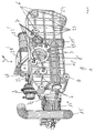
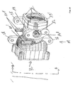
- Figs. 1, 2 and 4 show a multifunctional module 1 for an internal combustion engine, forming a structural assembly and incorporating the functions of exhaust gas cooling and of regulation, at least in part, of the circulation flows in the cooling circuit of said engine.
- This module 1 is characterised in that said structural assembly comprises a first functional unit 2 incorporating, on the one hand, a part at least of an exhaust gas recirculation circuit and a heat exchanger for cooling said gases, preferably of elongated form, together with at least one component 13, 13' for regulating/diverting the gas flow, and, on the other hand, a part at least of the engine cooling circuit, with at least the water outlet casing 4 and a thermostatic component 5 for regulating the flow therein, and in that said structural assembly comprises a second functional unit 3 in the form of a substantially flat plate-shaped body, forming a stiffening and fixing plate for the first functional unit 2 and a thermal isolation interface between the first functional unit and the engine block, said plate-shaped body 3 comprising on one of its faces sites 6 for fitting and fixing the first functional unit and on the other face sites 7 for fitting and fixing on the engine block.
- a compact multifunctional module 1 is achieved that can be fixed directly on the engine block without being subject to the constraints of a particular location imposed by the fixing and anchoring points of the first functional unit 2, the second functional unit 3 making it possible to mutually offset the fixing sites 6 and 7 respectively present on the two faces of said plate-shaped body forming this unit or body 3.
- the thermal isolation introduced by this body 3 associated possibly with a particular circulation of the coolant liquid, it is possible to produce at least part of the first functional unit 2 in a non-metallic material.
- the first unit 2 is substantially composed by assembly, on the one hand, of a first part 8 in plastics material comprising principally a first hollow body 9 forming a part at least of the tank 9' of the heat exchanger and a second hollow body 10 forming the water outlet casing 10, these two bodies 9 and 10 being adjacent and in fluidic communication, on the other hand, a second part 11 in a metallic material forming an exhaust gas distribution chamber 12, incorporating at least one gas flow regulation and/or diversion component 13, 13' and comprising inlet and outlet openings 14, 14' connected respectively to conduits 15, 15' forming the circulation circuit of said gases and, finally, a bundle of tubes 16, the majority of which are situated in the first hollow body 9 of the first part 8 and of which the inlet and outlet end portions 16' open into said distribution chamber 12, said bundle of tubes 16 being positioned and mounted in said first hollow body 9 by means of a support body 17 thus forming with it the heat exchanger,
- the exhaust gas distribution chamber 12 contains a regulation component 13 in the form of a valve controlling the admission of gases in the region of the openings of the inlet end portions 16' of the tubes 16 of the exchanger, preferably U-shaped, the position of said component 13 being determined by an actuator 18 outside said chamber 12.
- said distribution chamber 12 also comprises a regulation component 13, for example in the form of a flap gate or the like, controlling quantitatively the flow of exhaust gases admitted into said chamber 12 by the inlet opening 14 (Figs. 5 and 6).
- the regulation component 13 will thus control the rate of more or less cooled exhaust gas reinjected by means of the conduit 15 into the inlet manifold (not illustrated).
- the actuator 18, for example of the electric or hydraulic type, may advantageously be mounted on or at least supported by one of the two units 2 or 3, by means of a support part that is attached or formed in a single piece.
- the second part 11 has a generally bell-shaped structure and is assembled with the hollow body 9 forming the elongated tank of the first part 8 in the region of an opening in said body 9 through which pass the inlet and outlet end portions 16' of the tubes 16 of the exchanger, one part 17' in the form of a flat frame of the body 17 supporting the bundle of tubes 16 being sandwiched between the assembly edges of the second part 11 and said first hollow body 9 of the first part 8.
- the second metallic bell-shaped part 11 may have, at least in part, a double wall 11' with an intermediary interstice and/or a plurality of canals 11'" embedded in its thickness and/or attached, delimiting a coolant liquid circulation space, supply and discharge opening(s) or endpiece(s) 11" for said liquid being formed on or arranged in said second part 11, and for said bell-shaped second part 11 to have a tubular portion 19 in which are arranged exhaust gas inlet 14 and outlet 14' openings and which comprises an opening with a mounting site 19 for the actuator 13" of a regulation component 13' controlling quantitatively the flow of exhaust gases admitted into said chamber 12 through said inlet opening 13' (Figs. 10 to 12).
- the body 13'" of the component 13' can be seen in Fig. 11.
- said second hollow body 10 of the first part 8 forming the envelope of the water outlet casing 4 consists of two parts 20 and 20' assembled together, for example by vibration welding, a first part 20 being formed in a single piece with the first hollow body 9, while possibly comprising a liquid inlet or outlet endpiece 21, and the second attached part 20' possibly being formed in a single piece with a water outlet endpiece 21', said water outlet casing 4 also comprising mounting sites for a thermostatic component 5 for regulating the flow of liquid discharged by the water outlet endpiece 21' and a temperature sensor 22 in contact with the interior volume of said water outlet casing 4 (Figs. 1 to 5).
- the first hollow body 9 forming the tank of the exchanger may comprise a liquid outlet endpiece 9" formed in a single piece, allowing said liquid to be sent towards a fan convector.
- the substantially flat, plate-shaped body 3 consists of a metallic material comprising fitting and fixing sites 6 and 7 offset on one face in relation to the other, and has a rigid openwork structure similar to a lattice or grating consisting of a network of ribs in the form of rigid bands of material, preferably flat, interlaced in two dimensions, situated on edge in relation to the plane of the plate-shaped body 3 and delimited by a peripheral frame 24, also formed advantageously by a band of material situated on edge, so as to form a substantially hollow plate of a determined thickness, the fixing and fitting sites 6 and 7 being incorporated into said openwork structure, that structure being formed in a single piece, for example by moulding (Figs. 7 to 9).
- Such a meshed rigid structure allows a shaft of isolating air to be created, the sections of thermal bridges to be limited, the ribs to be cooled by allowing the circulation of air in the region of their open parts and a large dissipation surface to be provided.
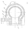
- the openwork structure forming the plate-shaped body 3 incorporates at least one portion of tubular conduit 25 extending perpendicularly to the plane of said body 3 and connecting, when module 1 is fitted, the outlet of the engine block's internal coolant liquid circulation circuit to an admission opening or endpiece 8' common to the two hollow bodies 9, 10 forming the first part 8 (Figs. 2, 3, 5, 7 to 9). It is thus possible to eliminate a separate conduit portion and shorten the length of that portion of the coolant liquid circulation circuit to the maximum.
- the flat openwork structure forming the plate-shaped body 3 incorporates at least one portion of conduit or tube 26, 27 extending in the thickness of said structure and connecting at least two openings 26', 27' to each other, inlet and outlet respectively, each opening onto one of the two opposite faces of the plate-shaped body 3 or both on the same face thereof (Figs. 2, 5, 7 to 9).
- This or these tube portion(s) 26, 27 will consist advantageously of communicating association of straight conduit segments opening to the exterior in the region of the peripheral frame 24 (sealing the emission holes with plugs), in order to allow the body 3 to be manufactured by moulding.
- the flat openwork structure incorporates at least one portion of conduit or tube 26 forming part of the exhaust gas recirculation circuit and connecting, for example, the engine block's exhaust gas outlet to the gas inlet opening 14 of the distribution chamber 12 of the second part 11.
- the flat openwork structure incorporates at least one portion of conduit or tube 27 forming part of the engine block's coolant circuit, said portion of conduit or tube being preferably connected or in fluidic communication with the tubular conduit portion 25 crossing said structure transversely.
- This incorporated conduit portion 27 could possibly serve to supply coolant liquid to the interstice of the double wall 11' of the part 11 and/or the canals 11" thereof.
- first and second parts 9 and 11 of the first functional unit 2 comprise fixing sites 28, for example in the form of eyelets or lugs, formed in a single piece for assembly with the corresponding fitting and fixing sites 6 of the second functional unit 3 in the form of a plate-shaped body.
- the invention also relates to a motor vehicle comprising an internal combustion engine, characterised in that it comprises a multifunctional module as described above.
- the invention also relates to a process for manufacturing such a module, characterised in that it consists of producing the first part 8, the second part 11 and the plate-shaped body 3 separately, then assembling the first part 8 with the second part 11, for example by means of nut and bolt units and, finally, fitting and fixing, for example by means of screws, the first functional unit 2 thus formed on the plate-shaped body 3.
Landscapes
- Engineering & Computer Science (AREA)
- Chemical & Material Sciences (AREA)
- Combustion & Propulsion (AREA)
- Mechanical Engineering (AREA)
- General Engineering & Computer Science (AREA)
- Exhaust-Gas Circulating Devices (AREA)
- Heat-Exchange Devices With Radiators And Conduit Assemblies (AREA)
- Air-Conditioning For Vehicles (AREA)
- Air Bags (AREA)
- Insulation, Fastening Of Motor, Generator Windings (AREA)
- Manufacture Of Motors, Generators (AREA)
- Ceramic Products (AREA)
Priority Applications (1)
| Application Number | Priority Date | Filing Date | Title |
|---|---|---|---|
| PL05108512T PL1643097T3 (pl) | 2004-09-20 | 2005-09-15 | Moduł wielofunkcyjny, pojazd silnikowy posiadający taki moduł oraz sposób wytwarzania takiego modułu |
Applications Claiming Priority (1)
| Application Number | Priority Date | Filing Date | Title |
|---|---|---|---|
| FR0409923A FR2875540B1 (fr) | 2004-09-20 | 2004-09-20 | Module multifonctionnel, vehicule a moteur comportant un tel module et procede de fabrication d'un tel module |
Publications (2)
| Publication Number | Publication Date |
|---|---|
| EP1643097A1 EP1643097A1 (en) | 2006-04-05 |
| EP1643097B1 true EP1643097B1 (en) | 2008-01-30 |
Family
ID=34949014
Family Applications (1)
| Application Number | Title | Priority Date | Filing Date |
|---|---|---|---|
| EP05108512A Expired - Lifetime EP1643097B1 (en) | 2004-09-20 | 2005-09-15 | Multifunctional module, motor vehicle comprising such a module and process for manufacturing such a module |
Country Status (6)
| Country | Link |
|---|---|
| US (1) | US7234453B2 (pl) |
| EP (1) | EP1643097B1 (pl) |
| AT (1) | ATE385283T1 (pl) |
| DE (1) | DE602005004579T2 (pl) |
| FR (1) | FR2875540B1 (pl) |
| PL (1) | PL1643097T3 (pl) |
Cited By (3)
| Publication number | Priority date | Publication date | Assignee | Title |
|---|---|---|---|---|
| DE102008064015A1 (de) | 2008-12-19 | 2010-07-01 | Daimler Ag | Abwärmenutzungsvorrichtung von Kraftfahrzeugen |
| DE102010009061A1 (de) | 2010-02-23 | 2011-08-25 | Pierburg GmbH, 41460 | Anordnung einer Kühlvorrichtung in einer Verbrennungskraftmaschine |
| US8099956B2 (en) | 2007-05-29 | 2012-01-24 | Behr Gmbh & Co. Kg | Arrangement of supercharging units for supercharging an internal combustion engine |
Families Citing this family (20)
| Publication number | Priority date | Publication date | Assignee | Title |
|---|---|---|---|---|
| FR2894295B1 (fr) * | 2005-12-01 | 2010-04-30 | Mark Iv Systemes Moteurs Sa | Module multifonctionnel pour moteur a combustion interne |
| US7363919B1 (en) * | 2007-01-05 | 2008-04-29 | Ford Global Technologies, Llc | Integrated exhaust gas recirculation valve and cooler system |
| FR2918715B1 (fr) * | 2007-07-13 | 2009-08-28 | Mark Iv Systemes Moteurs Soc P | Collecteur d'admission a double plenum et vehicule integrant un tel collecteur |
| FR2920706B1 (fr) * | 2007-09-12 | 2010-01-22 | Mark Iv Systemes Moteurs Sa | Module multifonctionnel pour moteur a combustion interne |
| ES2299405B1 (es) * | 2007-10-09 | 2009-09-11 | Dayco Ensa S.L. | Modulo integrado egr/refrigeracion para un motor de combustion interna. |
| DE102007049336B4 (de) | 2007-10-12 | 2019-09-05 | Mahle International Gmbh | Multifunktionales Modul zur Anbringung an einer Verbrennungskraftmaschine und zur Führung von Fluiden |
| WO2009127063A1 (en) * | 2008-04-17 | 2009-10-22 | Dana Canada Corporation | U-flow heat exchanger |
| DE102008047535B4 (de) | 2008-09-16 | 2014-01-09 | Pierburg Gmbh | Abgaskühlmodul für eine Verbrennungskraftmaschine |
| KR101509786B1 (ko) | 2009-09-28 | 2015-04-06 | 현대자동차주식회사 | 센서 포트 삽입형 실리콘 호스 및 그 제조방법 |
| DE102010014845A1 (de) | 2010-04-13 | 2011-10-13 | Pierburg Gmbh | Vorkühler |
| DE102010045259A1 (de) | 2010-09-14 | 2012-03-15 | Pierburg Gmbh | Kühlanordnung |
| DE102011007748A1 (de) * | 2011-04-20 | 2012-10-25 | Behr Gmbh & Co. Kg | Abgaskühler zum Kühlen von Verbrennungsabgas einer Verbrennungskraftmaschine, Wassersammeladapter, Abgaskühlsystem und Verfahren zum Herstellen eines Abgaskühlsystems |
| DE102013215614B4 (de) | 2013-08-07 | 2025-07-10 | Volkswagen Aktiengesellschaft | Funktionsmodul für einen Motor |
| US9303595B2 (en) | 2013-08-27 | 2016-04-05 | Deere & Company | Exhaust gas recirculation cooler mount |
| KR20150075421A (ko) * | 2013-12-17 | 2015-07-06 | 현대자동차주식회사 | 터보차저를 갖는 엔진시스템 |
| DE102015006100A1 (de) * | 2015-05-09 | 2016-11-10 | Motorenfabrik Hatz Gmbh & Co Kg | Vorrichtung und Verfahren zur Abgasrückführung |
| EP3232043B1 (en) * | 2016-04-14 | 2018-06-06 | FCA Italy S.p.A. | Multi-functional module for an internal combustion engine of a motor-vehicle |
| JP6619375B2 (ja) * | 2017-03-24 | 2019-12-11 | ヤンマー株式会社 | エンジン装置 |
| US11486337B2 (en) * | 2019-09-06 | 2022-11-01 | Deere & Company | Integrated exhaust system apparatus |
| JP7541838B2 (ja) * | 2020-03-13 | 2024-08-29 | ヤンマーパワーテクノロジー株式会社 | エンジン |
Family Cites Families (16)
| Publication number | Priority date | Publication date | Assignee | Title |
|---|---|---|---|---|
| US4134377A (en) * | 1977-09-29 | 1979-01-16 | Borg-Warner Corporation | Exhaust gas recirculation control valve and heat exchanger |
| US5970960A (en) * | 1996-09-18 | 1999-10-26 | Nissan Motor Co., Ltd. | Exhaust gas recirculation system of internal combustion engine |
| US5732688A (en) * | 1996-12-11 | 1998-03-31 | Cummins Engine Company, Inc. | System for controlling recirculated exhaust gas temperature in an internal combustion engine |
| JP3775926B2 (ja) * | 1998-06-22 | 2006-05-17 | 日産ディーゼル工業株式会社 | Egr装置 |
| US6237547B1 (en) * | 1998-09-10 | 2001-05-29 | Yamaha Hatsudoki Kabushiki Kaisha | Engine cooling arrangement |
| US6116026A (en) * | 1998-12-18 | 2000-09-12 | Detroit Diesel Corporation | Engine air intake manifold having built-in intercooler |
| FR2792968B1 (fr) * | 1999-04-29 | 2001-06-29 | Westaflex Automobile | Echangeur thermique en plastique et acier destine a etre dispose dans un circuit d'admission d'air d'un moteur, notamment dans un repartiteur comportant deux chambres et element du circuit d'admission d'air d'un moteur |
| GB9921819D0 (en) * | 1999-09-16 | 1999-11-17 | Transtec Plc | Gas recirculation system |
| US6186127B1 (en) * | 1999-09-20 | 2001-02-13 | Siemens Canada Limited | Coolant manifold adapter for integrated mounting of EEGR valve and throttle body on an engine |
| MXPA02005761A (es) * | 1999-12-14 | 2004-09-10 | Cooperstandard Automotive Flui | Valvula y enfriador egr integrados. |
| US6513507B2 (en) * | 2000-01-26 | 2003-02-04 | International Engine Intellectual Property Company, L.D.C. | Intake manifold module |
| DE10011954A1 (de) * | 2000-03-11 | 2001-09-13 | Modine Mfg Co | Abgaswärmetauscher in einer Abgasrückführungsanordnung |
| DE10119484B4 (de) * | 2001-04-20 | 2018-01-04 | Bayerische Motoren Werke Aktiengesellschaft | Flüssigkeitsgekühlte Brennkraftmaschine mit einem Abgasrückführsystem |
| JP4065239B2 (ja) * | 2002-01-16 | 2008-03-19 | 三菱電機株式会社 | 排気ガス再循環装置 |
| JP4473116B2 (ja) * | 2002-05-15 | 2010-06-02 | ベール ゲーエムベーハー ウント コー カーゲー | 切換可能な排気熱交換器 |
| US7108193B2 (en) * | 2003-12-29 | 2006-09-19 | Wahler Metalurgica Ltda | Integration of a thermostat in the recycling system of the vehicular exhaust gas recirculation (EGR) system |
-
2004
- 2004-09-20 FR FR0409923A patent/FR2875540B1/fr not_active Expired - Fee Related
-
2005
- 2005-09-15 AT AT05108512T patent/ATE385283T1/de not_active IP Right Cessation
- 2005-09-15 EP EP05108512A patent/EP1643097B1/en not_active Expired - Lifetime
- 2005-09-15 PL PL05108512T patent/PL1643097T3/pl unknown
- 2005-09-15 DE DE602005004579T patent/DE602005004579T2/de not_active Expired - Lifetime
- 2005-09-19 US US11/228,287 patent/US7234453B2/en not_active Expired - Lifetime
Cited By (4)
| Publication number | Priority date | Publication date | Assignee | Title |
|---|---|---|---|---|
| US8099956B2 (en) | 2007-05-29 | 2012-01-24 | Behr Gmbh & Co. Kg | Arrangement of supercharging units for supercharging an internal combustion engine |
| DE102008064015A1 (de) | 2008-12-19 | 2010-07-01 | Daimler Ag | Abwärmenutzungsvorrichtung von Kraftfahrzeugen |
| DE102010009061A1 (de) | 2010-02-23 | 2011-08-25 | Pierburg GmbH, 41460 | Anordnung einer Kühlvorrichtung in einer Verbrennungskraftmaschine |
| DE102010009061B4 (de) * | 2010-02-23 | 2014-05-28 | Pierburg Gmbh | Anordnung einer Kühlvorrichtung in einer Verbrennungskraftmaschine |
Also Published As
| Publication number | Publication date |
|---|---|
| DE602005004579T2 (de) | 2009-02-19 |
| FR2875540A1 (fr) | 2006-03-24 |
| FR2875540B1 (fr) | 2007-03-16 |
| EP1643097A1 (en) | 2006-04-05 |
| US20060207578A1 (en) | 2006-09-21 |
| PL1643097T3 (pl) | 2008-09-30 |
| DE602005004579D1 (de) | 2008-03-20 |
| ATE385283T1 (de) | 2008-02-15 |
| US7234453B2 (en) | 2007-06-26 |
Similar Documents
| Publication | Publication Date | Title |
|---|---|---|
| EP1643097B1 (en) | Multifunctional module, motor vehicle comprising such a module and process for manufacturing such a module | |
| US10305154B2 (en) | Apparatus for controlling temperature of coolant in water-cooled battery system and method thereof | |
| KR101703606B1 (ko) | 차량용 열교환기 | |
| JP5220008B2 (ja) | 内燃機関のガス流を冷却する装置 | |
| JP2012229906A (ja) | 車両用熱交換器 | |
| US20130061584A1 (en) | Exhaust Gas Heat Recovery Device | |
| JP2010249129A (ja) | チャージエアクーラ及び冷却システム | |
| JP2010127143A (ja) | チャージエアクーラ | |
| US10422307B2 (en) | Air intake manifold | |
| JP2015523495A (ja) | 新気供給装置 | |
| EP2792988B1 (en) | Integrated heat exchanger for a vehicle | |
| JP2013113578A (ja) | 車両用熱交換器 | |
| KR20200145880A (ko) | 차량의 통합열관리모듈 | |
| US20120199319A1 (en) | Arrangement for cooling the exhaust gas of a motor vehicle | |
| SE532319C2 (sv) | Värmeväxlare och sätt att tillverka denna | |
| EP2900951B1 (en) | Marine adaption of a diesel engine | |
| KR20230058967A (ko) | 차량용 콘덴서 | |
| US10220699B1 (en) | Heat exchanger including active grille shutters | |
| EP1793115B1 (en) | Multifunctional module for an internal-combustion engine | |
| CN107221728A (zh) | 一种48v系统锂电池散热结构 | |
| KR200410837Y1 (ko) | 히팅수단을 갖는 선박용 엔진룸 통기장치 | |
| EP2037116B1 (en) | Multifunctional module for an internal combustion engine | |
| KR102131651B1 (ko) | 열 전달 장치 | |
| US20220144077A1 (en) | Shutter device for vehicle | |
| JP2014196725A (ja) | 吸気冷却装置 |
Legal Events
| Date | Code | Title | Description |
|---|---|---|---|
| PUAI | Public reference made under article 153(3) epc to a published international application that has entered the european phase |
Free format text: ORIGINAL CODE: 0009012 |
|
| AK | Designated contracting states |
Kind code of ref document: A1 Designated state(s): AT BE BG CH CY CZ DE DK EE ES FI FR GB GR HU IE IS IT LI LT LU LV MC NL PL PT RO SE SI SK TR |
|
| AX | Request for extension of the european patent |
Extension state: AL BA HR MK YU |
|
| 17P | Request for examination filed |
Effective date: 20061004 |
|
| 17Q | First examination report despatched |
Effective date: 20061103 |
|
| AKX | Designation fees paid |
Designated state(s): AT BE BG CH CY CZ DE DK EE ES FI FR GB GR HU IE IS IT LI LT LU LV MC NL PL PT RO SE SI SK TR |
|
| GRAP | Despatch of communication of intention to grant a patent |
Free format text: ORIGINAL CODE: EPIDOSNIGR1 |
|
| GRAS | Grant fee paid |
Free format text: ORIGINAL CODE: EPIDOSNIGR3 |
|
| GRAA | (expected) grant |
Free format text: ORIGINAL CODE: 0009210 |
|
| RIN1 | Information on inventor provided before grant (corrected) |
Inventor name: VETOIS, JACQUES Inventor name: GALLINO, MARCO Inventor name: ALVES, ANTHONY |
|
| AK | Designated contracting states |
Kind code of ref document: B1 Designated state(s): AT BE BG CH CY CZ DE DK EE ES FI FR GB GR HU IE IS IT LI LT LU LV MC NL PL PT RO SE SI SK TR |
|
| REG | Reference to a national code |
Ref country code: GB Ref legal event code: FG4D |
|
| REG | Reference to a national code |
Ref country code: CH Ref legal event code: EP |
|
| REG | Reference to a national code |
Ref country code: IE Ref legal event code: FG4D |
|
| REF | Corresponds to: |
Ref document number: 602005004579 Country of ref document: DE Date of ref document: 20080320 Kind code of ref document: P |
|
| PG25 | Lapsed in a contracting state [announced via postgrant information from national office to epo] |
Ref country code: IS Free format text: LAPSE BECAUSE OF FAILURE TO SUBMIT A TRANSLATION OF THE DESCRIPTION OR TO PAY THE FEE WITHIN THE PRESCRIBED TIME-LIMIT Effective date: 20080530 Ref country code: LI Free format text: LAPSE BECAUSE OF FAILURE TO SUBMIT A TRANSLATION OF THE DESCRIPTION OR TO PAY THE FEE WITHIN THE PRESCRIBED TIME-LIMIT Effective date: 20080130 Ref country code: FI Free format text: LAPSE BECAUSE OF FAILURE TO SUBMIT A TRANSLATION OF THE DESCRIPTION OR TO PAY THE FEE WITHIN THE PRESCRIBED TIME-LIMIT Effective date: 20080130 Ref country code: CH Free format text: LAPSE BECAUSE OF FAILURE TO SUBMIT A TRANSLATION OF THE DESCRIPTION OR TO PAY THE FEE WITHIN THE PRESCRIBED TIME-LIMIT Effective date: 20080130 Ref country code: ES Free format text: LAPSE BECAUSE OF FAILURE TO SUBMIT A TRANSLATION OF THE DESCRIPTION OR TO PAY THE FEE WITHIN THE PRESCRIBED TIME-LIMIT Effective date: 20080511 |
|
| NLV1 | Nl: lapsed or annulled due to failure to fulfill the requirements of art. 29p and 29m of the patents act | ||
| REG | Reference to a national code |
Ref country code: CH Ref legal event code: PL |
|
| PG25 | Lapsed in a contracting state [announced via postgrant information from national office to epo] |
Ref country code: AT Free format text: LAPSE BECAUSE OF FAILURE TO SUBMIT A TRANSLATION OF THE DESCRIPTION OR TO PAY THE FEE WITHIN THE PRESCRIBED TIME-LIMIT Effective date: 20080130 |
|
| ET | Fr: translation filed | ||
| PG25 | Lapsed in a contracting state [announced via postgrant information from national office to epo] |
Ref country code: BE Free format text: LAPSE BECAUSE OF FAILURE TO SUBMIT A TRANSLATION OF THE DESCRIPTION OR TO PAY THE FEE WITHIN THE PRESCRIBED TIME-LIMIT Effective date: 20080130 Ref country code: PT Free format text: LAPSE BECAUSE OF FAILURE TO SUBMIT A TRANSLATION OF THE DESCRIPTION OR TO PAY THE FEE WITHIN THE PRESCRIBED TIME-LIMIT Effective date: 20080630 Ref country code: SI Free format text: LAPSE BECAUSE OF FAILURE TO SUBMIT A TRANSLATION OF THE DESCRIPTION OR TO PAY THE FEE WITHIN THE PRESCRIBED TIME-LIMIT Effective date: 20080130 Ref country code: LV Free format text: LAPSE BECAUSE OF FAILURE TO SUBMIT A TRANSLATION OF THE DESCRIPTION OR TO PAY THE FEE WITHIN THE PRESCRIBED TIME-LIMIT Effective date: 20080130 |
|
| REG | Reference to a national code |
Ref country code: PL Ref legal event code: T3 |
|
| PG25 | Lapsed in a contracting state [announced via postgrant information from national office to epo] |
Ref country code: SK Free format text: LAPSE BECAUSE OF FAILURE TO SUBMIT A TRANSLATION OF THE DESCRIPTION OR TO PAY THE FEE WITHIN THE PRESCRIBED TIME-LIMIT Effective date: 20080130 Ref country code: CZ Free format text: LAPSE BECAUSE OF FAILURE TO SUBMIT A TRANSLATION OF THE DESCRIPTION OR TO PAY THE FEE WITHIN THE PRESCRIBED TIME-LIMIT Effective date: 20080130 Ref country code: DK Free format text: LAPSE BECAUSE OF FAILURE TO SUBMIT A TRANSLATION OF THE DESCRIPTION OR TO PAY THE FEE WITHIN THE PRESCRIBED TIME-LIMIT Effective date: 20080130 Ref country code: NL Free format text: LAPSE BECAUSE OF FAILURE TO SUBMIT A TRANSLATION OF THE DESCRIPTION OR TO PAY THE FEE WITHIN THE PRESCRIBED TIME-LIMIT Effective date: 20080130 Ref country code: SE Free format text: LAPSE BECAUSE OF FAILURE TO SUBMIT A TRANSLATION OF THE DESCRIPTION OR TO PAY THE FEE WITHIN THE PRESCRIBED TIME-LIMIT Effective date: 20080430 |
|
| PG25 | Lapsed in a contracting state [announced via postgrant information from national office to epo] |
Ref country code: RO Free format text: LAPSE BECAUSE OF FAILURE TO SUBMIT A TRANSLATION OF THE DESCRIPTION OR TO PAY THE FEE WITHIN THE PRESCRIBED TIME-LIMIT Effective date: 20080130 |
|
| PGFP | Annual fee paid to national office [announced via postgrant information from national office to epo] |
Ref country code: PL Payment date: 20080916 Year of fee payment: 4 |
|
| PLBE | No opposition filed within time limit |
Free format text: ORIGINAL CODE: 0009261 |
|
| STAA | Information on the status of an ep patent application or granted ep patent |
Free format text: STATUS: NO OPPOSITION FILED WITHIN TIME LIMIT |
|
| 26N | No opposition filed |
Effective date: 20081031 |
|
| PG25 | Lapsed in a contracting state [announced via postgrant information from national office to epo] |
Ref country code: LT Free format text: LAPSE BECAUSE OF FAILURE TO SUBMIT A TRANSLATION OF THE DESCRIPTION OR TO PAY THE FEE WITHIN THE PRESCRIBED TIME-LIMIT Effective date: 20080130 |
|
| PG25 | Lapsed in a contracting state [announced via postgrant information from national office to epo] |
Ref country code: BG Free format text: LAPSE BECAUSE OF FAILURE TO SUBMIT A TRANSLATION OF THE DESCRIPTION OR TO PAY THE FEE WITHIN THE PRESCRIBED TIME-LIMIT Effective date: 20080430 Ref country code: MC Free format text: LAPSE BECAUSE OF NON-PAYMENT OF DUE FEES Effective date: 20080930 Ref country code: EE Free format text: LAPSE BECAUSE OF FAILURE TO SUBMIT A TRANSLATION OF THE DESCRIPTION OR TO PAY THE FEE WITHIN THE PRESCRIBED TIME-LIMIT Effective date: 20080130 |
|
| PG25 | Lapsed in a contracting state [announced via postgrant information from national office to epo] |
Ref country code: IE Free format text: LAPSE BECAUSE OF NON-PAYMENT OF DUE FEES Effective date: 20080915 Ref country code: CY Free format text: LAPSE BECAUSE OF FAILURE TO SUBMIT A TRANSLATION OF THE DESCRIPTION OR TO PAY THE FEE WITHIN THE PRESCRIBED TIME-LIMIT Effective date: 20080130 |
|
| GBPC | Gb: european patent ceased through non-payment of renewal fee |
Effective date: 20090915 |
|
| PG25 | Lapsed in a contracting state [announced via postgrant information from national office to epo] |
Ref country code: LU Free format text: LAPSE BECAUSE OF NON-PAYMENT OF DUE FEES Effective date: 20080915 Ref country code: HU Free format text: LAPSE BECAUSE OF FAILURE TO SUBMIT A TRANSLATION OF THE DESCRIPTION OR TO PAY THE FEE WITHIN THE PRESCRIBED TIME-LIMIT Effective date: 20080731 |
|
| PG25 | Lapsed in a contracting state [announced via postgrant information from national office to epo] |
Ref country code: TR Free format text: LAPSE BECAUSE OF FAILURE TO SUBMIT A TRANSLATION OF THE DESCRIPTION OR TO PAY THE FEE WITHIN THE PRESCRIBED TIME-LIMIT Effective date: 20080130 |
|
| PG25 | Lapsed in a contracting state [announced via postgrant information from national office to epo] |
Ref country code: GR Free format text: LAPSE BECAUSE OF FAILURE TO SUBMIT A TRANSLATION OF THE DESCRIPTION OR TO PAY THE FEE WITHIN THE PRESCRIBED TIME-LIMIT Effective date: 20080501 |
|
| PG25 | Lapsed in a contracting state [announced via postgrant information from national office to epo] |
Ref country code: GB Free format text: LAPSE BECAUSE OF NON-PAYMENT OF DUE FEES Effective date: 20090915 |
|
| PG25 | Lapsed in a contracting state [announced via postgrant information from national office to epo] |
Ref country code: PL Free format text: LAPSE BECAUSE OF NON-PAYMENT OF DUE FEES Effective date: 20090915 |
|
| REG | Reference to a national code |
Ref country code: PL Ref legal event code: LAPE |
|
| PGFP | Annual fee paid to national office [announced via postgrant information from national office to epo] |
Ref country code: IT Payment date: 20080930 Year of fee payment: 4 |
|
| PGFP | Annual fee paid to national office [announced via postgrant information from national office to epo] |
Ref country code: DE Payment date: 20120927 Year of fee payment: 8 |
|
| REG | Reference to a national code |
Ref country code: DE Ref legal event code: R119 Ref document number: 602005004579 Country of ref document: DE Effective date: 20140401 |
|
| PG25 | Lapsed in a contracting state [announced via postgrant information from national office to epo] |
Ref country code: DE Free format text: LAPSE BECAUSE OF NON-PAYMENT OF DUE FEES Effective date: 20140401 |
|
| REG | Reference to a national code |
Ref country code: FR Ref legal event code: PLFP Year of fee payment: 12 |
|
| REG | Reference to a national code |
Ref country code: FR Ref legal event code: PLFP Year of fee payment: 13 |
|
| REG | Reference to a national code |
Ref country code: FR Ref legal event code: PLFP Year of fee payment: 14 |
|
| P01 | Opt-out of the competence of the unified patent court (upc) registered |
Effective date: 20230620 |
|
| PGFP | Annual fee paid to national office [announced via postgrant information from national office to epo] |
Ref country code: FR Payment date: 20240924 Year of fee payment: 20 |