EP1642716B1 - Method and apparatus for adjusting ink supply amount for a printing press - Google Patents
Method and apparatus for adjusting ink supply amount for a printing press Download PDFInfo
- Publication number
- EP1642716B1 EP1642716B1 EP05090307A EP05090307A EP1642716B1 EP 1642716 B1 EP1642716 B1 EP 1642716B1 EP 05090307 A EP05090307 A EP 05090307A EP 05090307 A EP05090307 A EP 05090307A EP 1642716 B1 EP1642716 B1 EP 1642716B1
- Authority
- EP
- European Patent Office
- Prior art keywords
- ink
- ink fountain
- colors
- opening amounts
- fountain keys
- Prior art date
- Legal status (The legal status is an assumption and is not a legal conclusion. Google has not performed a legal analysis and makes no representation as to the accuracy of the status listed.)
- Expired - Lifetime
Links
Images


Classifications
-
- B—PERFORMING OPERATIONS; TRANSPORTING
- B41—PRINTING; LINING MACHINES; TYPEWRITERS; STAMPS
- B41F—PRINTING MACHINES OR PRESSES
- B41F31/00—Inking arrangements or devices
- B41F31/02—Ducts, containers, supply or metering devices
- B41F31/04—Ducts, containers, supply or metering devices with duct-blades or like metering devices
- B41F31/045—Remote control of the duct keys
-
- B—PERFORMING OPERATIONS; TRANSPORTING
- B41—PRINTING; LINING MACHINES; TYPEWRITERS; STAMPS
- B41F—PRINTING MACHINES OR PRESSES
- B41F31/00—Inking arrangements or devices
- B41F31/02—Ducts, containers, supply or metering devices
- B41F31/10—Applications of feed or duct rollers
- B41F31/12—Applications of feed or duct rollers adjustable for regulating supply
Definitions
- the present invention relates to a method and apparatus for adjusting the ink supply amount for a printing press, which adjust the amount of ink to be supplied to a plate by adjusting setting of the opening amount of an ink fountain key and the feed rate (rotation amount) of an ink fountain roller.
- a four-color rotary printing press shown in Fig. 18 has printing units 9-1 to 9-4 provided for four ink colors.
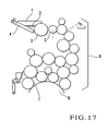
- An ink supply unit shown in Fig. 17 is provided in each of the printing units 9-1 to 9-4.
- the ink supply unit shown in Fig. 17 has an ink fountain 1.
- ink 2 stored in the ink fountain 1, an ink fountain roller 3, a plurality of ink fountain keys 4 (4-1 to 4-n) aligned in the axial direction of the ink fountain roller 3, an ink ductor roller 5, an ink roller group 6, a plate 7, and a plate cylinder 8.
- the amount of ink to be supplied from the ink fountain 1 to the ink fountain roller 3 is adjusted by adjusting the opening amounts of the ink fountain keys 4.
- the amount of ink to be supplied from the ink fountain roller 3 to the plate 7 through the ink roller group 6 is adjusted by adjusting the feed rate (rotation amount) of the ink fountain roller 3.
- a print sheet is printed with the ink finally supplied to the plate 7.
- the opening amount of each ink fountain key 4 is set in accordance with the image area ratio of each one of areas corresponding to the ink fountain keys 4, of the plate 7 by following the "conversion curve of the image area ratio to the opening amount of the ink fountain key" stored in advance.
- the feed rate of the ink fountain roller 3 is set in accordance with a predetermined reference ink feed rate.
- the opening amounts of the ink fountain keys 4 and the feed rate of the ink fountain roller 3 (ink feed rate) are set in units of printing units 9-1 to 9-4. More specifically, the "conversion curve of the image area ratio to the opening amount of the ink fountain key" and the reference ink feed rate are determined in units of ink colors.
- the operator finely adjusts the opening amounts of the ink fountain keys 4 separately, or the feed rate of the ink fountain roller 3, thereby dealing with the differences in standard density and the differences depending on the environment.
- This fine adjustment of the amount of ink to be supplied requires a very advanced technique and can be performed only by a skilled operator.
- the fine adjustment takes a very long period of time, leading to a delay in printing operation.
- the "conversion curve of the image area ratio to the opening amount of the ink fountain key" and the reference ink feed rate must be stored in units of ink colors, and a very large memory capacity is accordingly necessary.
- an ink supply amount adjusting method for a printing press according to any one of claims 1 and 11.
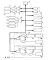
- the ink supply amount adjusting apparatus is comprised of a CPU (Central Processing Unit) 10, a ROM (Read Only Memory) 11, a RAM (Random Access Memory) 12, a switch group 13, a display 14, a drive 15 for a floppy disk or magnetic card, a printer 16, a densitometer 17, a measurement unit 18 for measuring the plate image area ratio of a testing plate, A/D (Analog-to-Digital) converters 19 and 20, input/output (I/O) interfaces 21 to 23, a reference density memory 24, a conversion curve memory 25, an ink feed rate memory 26, a correction amount memory 27, an ink fountain key drive unit 28, and an ink fountain roller drive unit 29.
- a CPU Central Processing Unit
- ROM Read Only Memory
- RAM Random Access Memory
- switch group 13 a display 14
- a drive 15 for a floppy disk or magnetic card a printer 16
- a densitometer 17 for measuring the plate image area ratio of a testing plate
- the CPU 10 obtains various kinds of input information supplied through the input/output interfaces 21 to 23 and performs various processing operations in accordance with programs stored in the ROM 11 while accessing the RAM 12.
- the standard densities in units of respective ink colors unique to the printing company are stored in the reference density memory 24 if necessary.
- standard densities in units of ink colors are stored in the memory 24.
- the "conversion curve of the image area ratio to the opening amount of the ink fountain key" serving as the reference common to the ink colors is stored in the conversion curve memory 25.
- the one and only standard characteristic common to the ink colors is stored in the memory 25.
- the ink feed rates in units of ink colors are stored in the ink feed rate memory 26.
- the reference ink feed rates in units of ink colors are stored in the memory 26 as the standard values.
- the correction amounts (increments/decrements) of the opening amounts of the ink fountain keys in units of ink colors are stored in the correction amount memory 27 as the uniform values for the respective ink fountain keys 4. More specifically, correction amounts common to all the ink fountain keys 4 ( Fig. 17 ) of each ink color are set as the correction amounts of the opening amounts of the ink fountain keys in units of ink colors. When the printing press is shipped from the manufacturer, the correction amounts of the opening amounts of the ink fountain keys are set to 0 for each ink color.
- the ink fountain key drive unit 28 is separately provided to correspond to each ink fountain key 4 of each of the printing units 9-1 to 9-4. More specifically, in each of the printing units 9-1 to 9-4, n (n is a positive integer of 2 or more) ink fountain key drive units 28 are provided to correspond to the n ink fountain keys 4. In this case, the opening amounts of the n ink fountain keys 4 with respect to the ink fountain roller 3 are separately adjusted by the n ink fountain key drive units 28 having the same arrangement.
- the ink fountain key drive unit 28 has an input/output interface 28A, a D/A converter 28B, a fountain key motor driver 28C, a fountain key motor 28D, a potentiometer 28E added to the fountain key motor 28D, and an A/D converter 28F.
- the ink fountain roller drive unit 29 is separately provided to correspond to each ink fountain roller 3 of each of the printing units 9-1 to 9-4. More specifically, in the four-color printing press, four ink fountain roller drive units 29 are provided to correspond to the four printing units 9-1 to 9-4. In this case, the feed rates of the ink fountain rollers 3 of the respective printing units 9-1 to 9-4 are separately adjusted by the four ink fountain roller drive units 29 having the same arrangement.
- the ink fountain roller drive unit 29 has an input/output interface 29A, a D/A converter 29B, a fountain roller driving motor driver 29C, a fountain roller driving motor 29D, a rotary encoder 29E added to the fountain roller driving motor 29D, an F/V converter 29F, and an A/D converter 29G.
- testing plates 7A having the same image as shown in Fig. 4 are used in units of ink colors.
- a color patch portion 7A1 and ink supply amount adjusting image portion 7A2 are formed on each testing plate 7A.
- the color patch portion 7A1 is a known image portion used for measuring printing quality, and is constituted by a plurality of patches (not shown) which are printed in the respective areas corresponding to the ink fountain keys 4 to be continuous in the direction of array of the ink fountain keys 4.
- the ink supply amount adjusting image portion 7A2 has a right-angled triangular shape, and the image area ratios within the respective areas corresponding to the ink fountain keys 4 gradually change in the direction along which the ink fountain keys 4 are aligned.
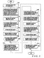
- the operator measures the image area ratios of the testing plate 7A with the measurement unit 18 and supplies them to the CPU 10 (step S101). More specifically, the operator measures the image area ratios, corresponding to the ink fountain keys 4, of the respective areas of the testing plate 7A, and supplies them to the CPU 10 through the A/D converter 20 and input/output interface 22.
- the CPU 10 calculates the reference opening amounts of the ink fountain keys 4 of the respective ink colors in accordance with the image area ratios, corresponding to the ink fountain keys 4, of the respective areas of the testing plate 7A by following the "conversion curve (standard characteristics) of the image area ratio to the opening amount of the ink fountain key" common to the ink colors (step S102) and stored in the conversion curve memory 25 in advance. At this time the reference opening amounts of the ink fountain keys 4 of the respective ink colors are common to the respective ink colors.
- the ink feed rates in units of ink colors are read out from the ink feed rate memory 26 (step S103), and the read-out ink feed rates of the respective ink colors are set in the ink fountain rollers 3 of the printing units 9-1 to 9-4 through the ink fountain roller drive unit 29.
- the reference opening amounts of the ink fountain keys 4 of the respective ink colors obtained in step S102 are also set through the ink fountain key drive unit 28 (step S104).
- the operator performs printing to acquire a printing sample (step S105).
- the density of each ink color of the acquired printing sample is measured with the densitometer 17 (step S106), and is supplied to the CPU 10 through the A/D converter 19 and input/output interface 21.
- the CPU 10 checks whether the density (measured density) of each area, corresponding to the ink fountain key 4, of each ink color of the printing sample coincides with the corresponding reference density (the reference density unique to the printing company) of each ink color stored in the reference density memory 24 in advance (step S107).
- the CPU 10 determines that the density must be adjusted. For the sake of descriptive convenience, assume that the measured density and the reference density do not coincide with each other in all areas of the respective ink colors.
- the operator adjusts the correction amounts of the opening amounts of the ink fountain keys in units of ink colors stored in the correction amount memory 27 and the ink feed rates of the respective ink colors stored in the ink feed rate memory 26 (step S108). More specifically, the operator increases or decreases the current correction amounts of the opening amounts of the ink fountain keys of the respective ink colors and the current ink feed rates in units of ink colors while monitoring them displayed on the display 14. The adjusted correction amounts of the opening amounts of the ink fountain keys and the adjusted ink feed rates, of the respective ink colors are overwritten in the correction amount memory 27 and ink feed rate memory 26.
- the CPU 10 reads out the adjusted correction amounts of the opening amounts of the ink fountain keys of the respective ink colors from the correction amount memory 27 (step S109).
- the CPU 10 then adds the read-out correction amounts of the opening amounts of the ink fountain keys of the respective ink colors to the reference opening amounts of the ink fountain keys 4 of the respective ink colors obtained in step S102, thereby correcting the opening amounts of the ink fountain keys 4 of the respective ink colors (step S110). More specifically, if the correction amounts are positive values, they are uniformly added to the opening amounts of the ink fountain keys 4; if they are negative values, they are uniformly subtracted from the opening amounts of the ink fountain keys 4.
- the CPU 10 then reads out the adjusted ink feed rates of the respective ink colors from the ink feed rate memory 26 (step S111).
- the read-out ink feed rates of the respective ink colors, and the opening amounts of the ink fountain keys 4 of the respective ink colors corrected in step S110, are set in the CPU 10 through the ink fountain roller drive unit 29 and ink fountain key drive unit 28 (step S112).
- each ink color if the measured density obtained in step S107 is a constant value A, as indicated by a characteristic curve I shown in Fig. 5A , regardless of the image area ratio, this characteristic curve is changed by adjusting the ink feed rate in step S112. For example, when the ink feed rate is increased, the density increases, as indicated by a characteristic curve II. The density does not increase sharply at a portion with a low image area ratio, but increases gradually as the image area ratio increases, and stays at a substantially constant value when the image area ratio reaches a certain value.
- each ink color if the measured density obtained in step S107 is a constant value A, as indicated by a characteristic curve I shown in Fig. 5B , regardless of the image area ratio, this characteristic curve is changed by adjusting the opening amounts of the respective ink fountain keys 4 in step S112. For example, when the opening amounts of the ink fountain keys 4 are uniformly increased, the density increases, as indicated by a characteristic curve III. The density increases largely at a portion with a low image area ratio, but decreases gradually as the image area ratio increases, and stays at substantially a constant value when the image area ratio reaches a certain value.
- step S112 since both the ink feed rates and the opening amounts of the ink fountain keys are adjusted, the characteristic curves II and III are combined to provide a characteristic curve IV, as shown in Fig. 5C .
- the printing density of each ink color can be adjusted to a desired density (reference density) B by translation without changing the "conversion curve of the image area ratio to the opening amount of the ink fountain key" common to the respective ink colors and stored in the conversion curve memory 25.
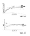
- Fig. 15 shows the conventional "conversion curve of the image area ratio to the opening amount of ink fountain key" of each of cyan, magenta, yellow, and black which are the respective ink colors.
- the density as shown in Fig. 16 is obtained.
- the density of black has a density distribution substantially opposite to that obtained when the feed rate of the ink fountain roller is increased
- the density of yellow has a density distribution substantially opposite to that obtained when the opening amounts of the ink fountain keys are uniformly increased.
- the density distributions of the respective ink colors can be set almost uniform by uniformly increasing/decreasing the feed rate of the ink fountain roller or the opening amounts of the ink fountain keys.
- the density distributions of the respective ink colors can be set uniform.
- the densities of the respective ink colors are different from the corresponding reference densities.
- the densities of portions with the respective image area ratios can be changed substantially uniformly by uniformly increasing/decreasing the feed rate of the ink fountain roller or the opening amounts of the ink fountain keys. By this adjustment, the densities of the respective ink colors can be set to match the reference densities of the corresponding ink colors of each printing company.
- the feed rate of the ink fountain key roller and the opening amounts of the ink fountain keys are uniformly increased or decreased by using the "conversion curve of the image area ratio to the opening amount of the ink fountain key" common to the ink colors, the amount of ink to be supplied, which matches the reference density of each ink color of each printing company or the printing condition, can be obtained.
- the appropriate amount of ink to be supplied can be obtained easily by using the increment(s)/decrement(s) of the feed rate of the ink fountain roller and the opening amounts of the ink fountain keys.
- step S112 After the ink feed rate and the opening amounts of the ink fountain keys are set in step S112, the operator performs printing again with the testing plate 7A being set on the plate cylinder 8 of each ink color, and acquires a printing sample (step S113). The operator then measures the density of each ink color of the acquired printing sample (step S114). The CPU 10 checks whether the measured density of each area, corresponding to the ink fountain key 4, of the corresponding ink color of the acquired printing sample coincides with the reference density in the same manner as in the previous step S107 (step S115).
- the CPU 10 repeats the steps S108 to S115 until the measured densities of all areas of the respective ink colors coincide with the reference densities.
- the CPU 10 ends adjustment of the correction amounts of the opening amounts of the ink fountain keys and the ink feed rates performed before the start of printing.
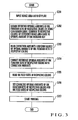
- the operator Prior to the start of printing with the plate 7 of each ink color being mounted, the operator separately measures the image area ratio of the plate 7 of each ink color with the plate image area ratio measurement unit 18, and supplies the obtained ratio to the CPU 10 (step S201). More specifically, the operator measures the image area ratios, corresponding to the ink fountain keys 4, of the respective areas of the plates 7 of the respective ink colors, and supplies the measured image area ratios to the CPU 10 through the A/D converter 20 and input/output interface 22.
- the CPU 10 obtains the reference opening amounts of the ink fountain keys 4 of the respective ink colors in accordance with the image area ratios of the respective areas, corresponding to the ink fountain keys 4, of the plate 7 of the respective ink colors by following the "conversion curve of the image area ratio to the opening amount of the ink fountain key" common to the ink colors (step S202) and stored in the conversion curve memory 25 in advance.
- the operator then reads out the correction amounts of the opening amounts of the ink fountain keys of the respective ink colors from the correction amount memory 27 (step S203).
- the CPU 10 then adds the read-out correction amounts of the opening amounts of the ink fountain keys of the respective ink colors to the reference opening amounts of the ink fountain keys 4 of the respective ink colors obtained in step S202, thereby obtaining preset values of the opening amounts of the ink fountain keys 4 for the respective ink colors (step S204). More specifically, if the correction amounts are positive amounts, they are uniformly added to the opening amounts of the ink fountain keys 4; if they are negative values, they are uniformly subtracted from the opening amounts of the ink fountain keys 4.
- the CPU 10 then reads out the ink feed rates of the respective ink colors from the ink feed rate memory 26 (step S205).
- the read-out ink feed rates of the respective ink colors, and the opening amounts of the ink fountain keys 4 of the respective ink colors obtained in step S204, are set in the CPU 10 through the ink fountain roller drive unit 29 and ink fountain key drive unit 28 (step S206). Printing is then started (step S207).
- the ink feed rates of the respective ink colors in the ink feed rate memory 26 and the correction amounts of the opening amounts of the ink fountain keys of the respective ink colors in the correction amount memory 27 are adjusted such that the reference densities of the respective ink colors unique to the printing company are obtained by repeating steps S108 to S115 before the start of printing regardless of the image area ratios. Therefore, appropriate ink supply amounts can be obtained from the beginning.
- the opening amounts of the ink fountain keys 4 and the ink feed rates, of the respective ink colors are set in accordance with the reference densities unique to the printing company to be employed and the printing environmental conditions, and after that the operator adjusts the opening amounts of the ink fountain keys and the ink feed rates of the respective ink colors without regularity while repeating printing test of the printing products with the plates 7, such that appropriate amounts of ink are supplied.
- such ink supply amount adjustment with the plates 7 being mounted is not necessary. Appropriate amounts of ink can be obtained immediately after the plates 7 are mounted.
- the correction amounts of the opening amounts of the ink fountain keys of the respective ink colors are uniform, the correction amounts and ink feed rates can be adjusted before the start of printing easily within a short period of time when compared to a method of setting separate correction amounts in units of ink fountain keys.
- the basic "conversion curve of the image area ratio to the opening amount of the ink fountain key" determined by the printing machine manufacturer and common to the ink colors need not be changed, and the adjusting operation can be simplified.
- the memory capacity of the conversion curve memory 25 can be greatly reduced. More specifically, conventionally, since the "conversion curve of the image area ratio to the opening amount of the ink fountain key" is stored in units of ink colors, a large memory capacity is needed. According to the present invention, the one and only "conversion curve of the image area ratio to the opening amount of the ink fountain key" need be stored, and a large memory capacity is not needed.
- both the correction amounts of the opening amounts of the ink fountain keys and the ink feed rates, of the respective ink colors are adjusted.
- only either the correction amounts of the opening amounts of the ink fountain keys or the ink feed rates, of the respective ink colors need be adjusted.
- a desired density B can be obtained only by adjusting the correction amounts of the opening amounts of the ink fountain keys of the respective ink colors.
- a desired density B can be obtained only by adjusting the ink feed rates of the respective ink colors.
- the desired density B can be obtained only by adjusting the ink feed rates.
- the desired density B can be obtained only by adjusting the correction amounts of the opening amounts of the ink fountain keys.
- the ink supply amount adjusting apparatus has, in addition to the arrangement shown in Fig. 1 , a coefficient memory 30 for storing the coefficients of ink feed rates in units of ink colors.
- the coefficients of the ink feed rates in units of ink colors are set to "1" when the printing machine is shipped from the manufacturer.
- the one and only reference ink feed rate common to the ink colors is stored in an ink feed rate memory 26 when the printing machine is shipped from the manufacturer. Unlike the first embodiment, the reference ink feed rate common to the ink colors will not be overwritten.
- the correction amounts of the opening amounts of the ink fountain keys in units of ink colors stored in a correction amount memory 27 and the coefficients of the ink feed rates in units of ink colors stored in a coefficient memory 30 are adjusted. In this adjustment as well, testing plates 7A identical to that shown in Fig. 4 are used.
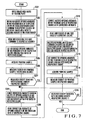
- steps S301 to S307 and S314 to S316 in Fig. 7 are the same as those of steps S101 to S107 and S113 to S115 in Fig. 2 , and a description thereof will accordingly be omitted.
- step S307 the operator adjusts the correction amounts of the opening amounts of the ink fountain keys of the respective ink colors stored in the correction amount memory 27 and the coefficients of the ink feed rates of the respective ink colors stored in the coefficient memory 30 (step S308). More specifically, the operator increases or decreases the current correction amounts of the opening amounts of the ink fountain keys and the current coefficients of the ink feed rates, of the respective ink colors while monitoring them displayed on a display 14. The adjusted correction amounts of the opening amounts of the ink fountain keys and the adjusted coefficients of the ink feed rates, of the respective ink colors are overwritten in the correction amount memory 27 and coefficient memory 30, respectively.
- the CPU 10 reads out the adjusted correction amounts of the opening amounts of the ink fountain keys of the respective ink colors from the correction amount memory 27 (step S309).
- the CPU 10 then adds the read-out correction amounts (increments/decrements) of the opening amounts of the ink fountain keys of the respective ink colors to the reference opening amounts of the ink fountain keys 4 of the respective ink colors obtained in step S302, thereby correcting the opening amounts of ink fountain keys 4 of the respective ink colors (step S310). More specifically, if the correction amounts are positive values, they are uniformly added to the opening amounts of the ink fountain keys 4; if they are negative values, they are uniformly subtracted from the opening amounts of the ink fountain keys 4.
- the CPU 10 then reads out the adjusted coefficients of the ink feed rates of the respective ink colors from the coefficient memory 30 (step S311).
- the CPU 10 multiplies the reference ink feed rate, read by the step S303 and common to the ink colors, by the read-out coefficients of the ink feed rates of the respective ink colors, thereby correcting the ink feed rates of the respective ink colors (step S312).
- the CPU 10 sets the opening amounts of the ink fountain keys 4 of the respective ink colors obtained in step S310 and the ink feed rates of the respective ink colors obtained in step S312 through an ink fountain key drive unit 28 and ink fountain roller drive unit 29 (step S313).
- the flow advances to step S315.
- steps S401 to S404 in Fig. 8 are the same as those of steps S201 to S204 in Fig. 3 , and a description thereof will accordingly be omitted.
- the CPU 10 reads out the reference ink feed rate common to the ink colors from the ink feed rate memory 26 in step S405, and reads the coefficients of the ink feed rates of the respective ink colors from the coefficient memory 30 (step S406).
- the CPU 10 then multiplies the reference ink feed rate, read in step S405 and common to the ink colors, by the: read-out coefficients of the ink feed rates of the respective ink colors, thereby obtaining preset values of the ink feed rates of the respective ink colors (step S407).
- the CPU 10 sets the opening amounts of the ink fountain keys 4 of the respective ink colors obtained in step S404, and the ink feed rates of the respective ink colors obtained in step S407 through the ink fountain key drive unit 28 and ink fountain roller drive unit 29 (step S408). Printing is then started (step S409).
- the ink feed rates of the respective ink colors are corrected by multiplying them by the coefficients.
- correction values are obtained and added to the reference ink feed rate, in the same manner as that performed when adjusting the opening amounts of the ink fountain keys, the same effect can be obtained.
- the ink supply amount adjusting apparatus has, in addition to the arrangement shown in Fig. 1 , a zero position memory 31 for storing the zero positions (origin positions) of the opening amounts of the ink fountain keys in units of ink colors.
- the operator measures the image area ratio of the testing plate 7A with a measurement unit 18 and supplies it to a CPU 10 (step S601).
- the CPU 10 reads out the zero positions of the opening amounts of the ink fountain keys of the respective ink colors stored in the zero position memory 31 (step 5602), and the correction amounts of the opening amounts of the ink fountain keys of the respective ink colors stored in the correction amount memory 27 (step S603).
- the CPU 10 adds the correction amounts (increments/decrements) of the opening amounts of the ink fountain keys of the respective ink colors to the readout zero positions of the opening amounts of the ink fountain keys of the respective ink colors, thereby correcting the zero positions of the opening amounts of the ink fountain keys of the respective ink colors (step S604). More specifically, if the correction amounts are positive values, they are uniformly added to the zero positions of the opening amounts of the ink fountain keys; if they are negative values, they are uniformly subtracted from the zero positions of the opening amounts of the ink fountain keys.
- the CPU 10 obtains the reference opening amounts of the ink fountain keys 4 of the respective ink colors in accordance with the image area ratios of the respective areas, corresponding to the ink fountain keys 4, of the plates 7 of the respective ink colors by following the "conversion curve of the image area ratio to the opening amount of the ink fountain key" common to the ink colors (step S605) and stored in a conversion curve memory 25 in advance.
- the operator then obtains the opening amounts of the ink fountain keys of the respective ink colors from the corrected zero positions of the opening amounts of the ink fountain keys of the respective ink colors obtained in step S604 and the reference opening amounts of the ink fountain keys of the respective ink colors obtained in step S605 (step S606).
- the CPU 10 reads out the ink feed rates of the respective ink colors from the ink feed rate memory 26 (step S607.). The CPU 10 then sets the read-out ink feed rates of the respective ink colors and the opening amounts of ink fountain keys 4 of the respective ink colors obtained in step S606 through an ink fountain roller drive unit 29 and ink fountain key drive unit 28 (step S608). After that, printing is started (step S609).
- the opening amounts of the ink fountain keys 4 of the respective ink colors are set with reference to the corrected zero positions of the opening amounts of the ink fountain keys of the respective ink colors. More specifically, the opening amounts.of the ink fountain keys 4 of the respective ink colors are set with reference to the zero positions that are adjusted such that the reference densities of the respective ink colors unique to the printing company can be obtained regardless of the image area ratio. Therefore, when the setting operation of the opening amounts is combined with the setting operation of the ink feed rates of the respective ink colors read from the ink feed rate memory 26, appropriate ink supply amounts can be obtained from the beginning.
- the ink supply amount adjusting mechanism has, in addition to the arrangement shown in Fig. 6 , a memory 31 for storing the zero positions (origin positions) of the opening amounts of the ink fountain keys in units of ink colors.
- the operator measures the image area ratio of the testing plate 7A with a measurement unit 18 and supplies it to a CPU 10 (step S801).
- the CPU 10 reads out the zero positions of the opening amounts of the ink fountain keys of the respective ink colors stored in the zero position memory 31 (step S802), and the correction amounts of the opening amounts of the ink fountain keys of the respective ink colors stored in the correction amount memory 27 (step S803).
- the CPU 10 adds the correction amounts (increments/decrements) of the opening amounts of the ink fountain keys of the respective ink colors to the read-out zero positions of the opening amounts of the ink fountain keys of the respective ink colors, thereby correcting the zero positions of the opening amounts of the ink fountain keys of the respective ink colors (step S804). More specifically, if the correction amounts are positive values, they are uniformly added to the zero positions of the opening amounts of the ink fountain keys; if they are negative values, they are uniformly subtracted from the zero positions of the opening amounts of the ink fountain keys.
- the CPU 10 obtains the reference opening amounts of the ink fountain keys 4 of the respective ink colors in accordance with the image area ratios of the respective areas, corresponding to ink fountain keys, of the plate 7 of the respective ink colors 4 by following the "conversion curve of the image area ratio to the opening amount of the ink fountain key" common to the ink colors (step S805) and stored in a conversion curve memory 25 in advance.
- the CPU 10 then obtains the opening amounts of the ink fountain keys of the respective ink colors from the corrected zero positions of the opening amounts of the ink fountain keys of the respective ink colors obtained in step S804 and the reference opening amounts of the ink fountain keys of the respective ink colors obtained in step S805 (step S806).
- the CPU 10 reads out the reference ink feed rate common to the ink colors from an ink feed rate memory 26 (step S807), and the coefficients of the ink feed rates of the respective ink colors from the coefficient memory 30 (step S808). The CPU 10 then multiplies the reference ink feed rate common to the ink colors and read in step S807 by the read-out coefficients of the ink feed rates of the respective ink colors, thereby obtaining preset values of the ink feed rates of the respective ink colors (step S809).
- the CPU 10 sets the opening amounts of the ink fountain keys 4 of the respective ink colors obtained in step S806 and the ink feed rates of the respective ink colors obtained in step S809 through an ink fountain key drive unit 28 and ink fountain roller drive unit 29. After that, printing is started (step S811).
- the opening amounts of the ink fountain keys 4 of the respective ink colors are set with reference to the corrected zero positions of the opening amounts of the ink fountain keys of the respective ink colors. More specifically, the opening amounts of the ink fountain keys 4 of the respective ink colors are set with reference to the zero positions that are adjusted such that the reference densities of the respective ink colors unique to the printing company can be obtained regardless of the image area ratio. Therefore, when the setting operation of the opening amounts is combined with the setting operation of the ink feed rates of the respective ink colors obtained in step S809, appropriate ink supply amounts can be obtained from the beginning.
- the ink feed rates of the respective ink colors are corrected by multiplying them by the coefficients.
- correction values are obtained and added to the reference ink feed rates, in the same manner as that performed when adjusting the opening amounts of the ink fountain keys, the same effect can be obtained.
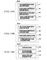
- Figs. 19A, 19B, and 19C show the relationships between the function blocks of the CPUs 10 of Figs. 1 , 9 , and 12 and their processing steps.
- a first reference opening amount calculating portion 101 performs the process of step S102 of Fig. 2
- an opening amount correction value calculating portion 102 performs the processes of steps S108 to S115 of Fig. 2 .
- a second reference opening amount calculating portion 103 performs the process of step S202 of Fig. 3
- an opening amount preset value calculating portion 104 performs the process of step S206 of Fig. 3 .
- a first reference opening amount calculating portion 201 performs the process of step S502 of Fig. 10
- an opening amount correction value calculating portion 202 performs the processes of steps S508 to S515 of Fig. 10 .
- An origin position correcting portion 203 performs the process of step S604 of Fig. 11
- an opening amount preset value calculating portion 204 performs the process of step S606 of Fig. 11 .
- an overwriting portion 301 performs the processes of steps S708 to S716 of Fig. 13
- a feed rate correction value setting portion 302 performs the process of step S808 of Fig. 14
- a feed rate preset value calculating portion 303 performs the process of step S809 of Fig. 14 .
- a CPU 10 of Fig. 12 can also have at least one functional block of the CPUs 10 of Figs. 1 and 9 .
- color matching in actual printing can be performed easily within a short period of time.
- at least one of the correction amounts/origin positions of the opening amounts of the ink fountain keys of the respective ink colors and the correction values of the ink feed rates of the respective ink colors is adjusted such that the reference densities of the respective ink colors unique to the printing company can be obtained regardless of the image area ratio before the start of printing, a higher effect can be obtained.
- the relationship between the image area ratio and the opening amounts of the ink fountain keys it suffices if only one reference value is set to be common to the respective ink colors. Therefore, no large memory capacity is needed, and the image capacity can be reduced greatly.
- the correction amounts of the opening amounts of the ink fountain keys and the correction amounts of the ink feed rates, of the ink colors can be overwritten. Therefore, the amount of ink to be supplied, which varies depending on the printing companies and the differences in the environment, can be adjusted easily within a short period of time by adjusting the correction values (increments/decrements) of the opening amounts of the ink fountain keys and the correction amounts of the ink feed rates, of the ink colors before the start of printing.
Abstract
Description
- The present invention relates to a method and apparatus for adjusting the ink supply amount for a
printing press, which adjust the amount of ink to be supplied to a plate by adjusting setting of the opening amount of an ink fountain key and the feed rate (rotation amount) of an ink fountain roller. - A four-color rotary printing press shown in
Fig. 18 has printing units 9-1 to 9-4 provided for four ink colors. An ink supply unit shown inFig. 17 is provided in each of the printing units 9-1 to 9-4. - The ink supply unit shown in
Fig. 17 has an ink fountain 1.ink 2 stored in the ink fountain 1, anink fountain roller 3, a plurality of ink fountain keys 4 (4-1 to 4-n) aligned in the axial direction of theink fountain roller 3, anink ductor roller 5, anink roller group 6, aplate 7, and a plate cylinder 8. - In the printing press having the above arrangement, the amount of ink to be supplied from the ink fountain 1 to the
ink fountain roller 3 is adjusted by adjusting the opening amounts of the ink fountain keys 4. The amount of ink to be supplied from theink fountain roller 3 to theplate 7 through theink roller group 6 is adjusted by adjusting the feed rate (rotation amount) of theink fountain roller 3. A print sheet is printed with the ink finally supplied to theplate 7. - The opening amount of each ink fountain key 4 is set in accordance with the image area ratio of each one of areas corresponding to the ink fountain keys 4, of the
plate 7 by following the "conversion curve of the image area ratio to the opening amount of the ink fountain key" stored in advance. The feed rate of theink fountain roller 3 is set in accordance with a predetermined reference ink feed rate. The opening amounts of the ink fountain keys 4 and the feed rate of the ink fountain roller 3 (ink feed rate) are set in units of printing units 9-1 to 9-4. More specifically, the "conversion curve of the image area ratio to the opening amount of the ink fountain key" and the reference ink feed rate are determined in units of ink colors. - Conventionally, since the "conversion curve of the image area ratio to the opening amount of the ink fountain key" and the reference ink feed rate are uniquely determined by the printing machine manufacturer, differences in standard density among the printing companies and differences depending on the environment are not considered. For this reason, the operator of each printing company actually checks the color of the printed printing product after the opening amounts of the respective ink fountain keys 4 and the feed rate of the
ink fountain roller 3 are set by using the standard characteristics in units of printing units 9-1 to 9-4. - In accordance with the result of color checking, the operator finely adjusts the opening amounts of the ink fountain keys 4 separately, or the feed rate of the
ink fountain roller 3, thereby dealing with the differences in standard density and the differences depending on the environment. This fine adjustment of the amount of ink to be supplied requires a very advanced technique and can be performed only by a skilled operator. The fine adjustment takes a very long period of time, leading to a delay in printing operation. - Also, conventionally, the "conversion curve of the image area ratio to the opening amount of the ink fountain key" and the reference ink feed rate must be stored in units of ink colors, and a very large memory capacity is accordingly necessary.
- It is the object of the present invention to provide a method and apparatus for adjusting the ink supply amount for a printing press, which can perform color matching for actual printing and set and adjust the amount of ink to be supplied easily and within a short period of time.
- It is another object of the present invention to provide a method and apparatus for adjusting the ink supply amount for a printing press, which do not require a very large memory capacity.
- In order to achieve the above objects, according to the present invention, there is provided an ink supply amount adjusting method for a printing press according to any one of
claims 1 and 11. -
-
Fig. 1 is a block diagram of an ink supply amount adjusting apparatus for a printing press according to a first embodiment not covered by the present invention; -
Fig. 2 is a flow chart for explaining the operation of the ink supply amount adjusting apparatus ofFig. 1 before the start of printing; -
Fig. 3 is a flow chart for explaining the operation of the ink supply amount adjusting apparatus ofFig. 1 at the start of printing; -
Fig. 4 is a plan view of a testing plate used in the ink supply amount adjusting apparatus ofFig. 1 ; -
Figs. 5A to 5C are graphs showing the relationship among the opening amount of the ink fountain key, the ink feed rate, and the reference printing density; -
Fig. 6 is a block diagram of an ink supply amount adjusting apparatus for a printing press according to a second embodiment not covered by the present invention; -
Fig. 7 is a flow chart for explaining the operation of the ink supply amount adjusting apparatus ofFig. 6 before the start of printing; -
Fig. 8 is a flow chart for explaining the operation of the ink supply amount adjusting apparatus ofFig. 6 at the start of printing; -
Fig. 9 is a block diagram of an ink supply amount adjusting apparatus for a printing press according to a third embodiment of the present invention; -
Fig. 10 is a flow chart for explaining the operation of the ink supply amount adjusting apparatus ofFig. 9 before the start of printing; -
Fig. 11 is a flow chart for explaining the operation of the ink supply amount adjusting apparatus ofFig. 9 at the start of printing; -
Fig. 12 is a block diagram of an ink supply amount adjusting apparatus for a printing press according to a fourth embodiment of the present invention; -
Fig. 13 is a flow chart for explaining the operation of the ink supply amount adjusting apparatus ofFig. 12 before the start of printing; -
Fig. 14 is a flow chart for explaining the operation of the ink supply amount adjusting apparatus ofFig. 12 at the start of printing; -
Fig. 15 is a graph showing the "conversion curve of the image area ratio to the opening amount of the ink fountain key" of each ink color; -
Fig. 16 is a graph showing the density obtained when the opening amount of the ink fountain key of an ink color is obtained from a corresponding conversion curve of cyan or magenta; -
Fig. 17 is a view schematically showing an ink supply unit for a printing unit of each ink color in a rotary printing press; -
Fig. 18 is a side view schematically showing a four-color rotary printing press; and -
Figs. 19A, 19B, and 19C are function block diagrams of the CPUs respectively shown inFigs. 1 ,9 , and12 . - The present invention will be described in detail with reference to the accompanying drawings. In the following description,
Figs. 17 and18 are also referred to. - Referring to
Fig. 1 , the ink supply amount adjusting apparatus is comprised of a CPU (Central Processing Unit) 10, a ROM (Read Only Memory) 11, a RAM (Random Access Memory) 12, aswitch group 13, adisplay 14, adrive 15 for a floppy disk or magnetic card, aprinter 16, adensitometer 17, ameasurement unit 18 for measuring the plate image area ratio of a testing plate, A/D (Analog-to-Digital)converters interfaces 21 to 23, areference density memory 24, aconversion curve memory 25, an inkfeed rate memory 26, acorrection amount memory 27, an ink fountainkey drive unit 28, and an ink fountainroller drive unit 29. - The
CPU 10 obtains various kinds of input information supplied through the input/output interfaces 21 to 23 and performs various processing operations in accordance with programs stored in theROM 11 while accessing theRAM 12. - The standard densities in units of respective ink colors unique to the printing company (in units of printing units) are stored in the
reference density memory 24 if necessary. Usually, when the printing press is shipped from the manufacturer, standard densities in units of ink colors are stored in thememory 24. The "conversion curve of the image area ratio to the opening amount of the ink fountain key" serving as the reference common to the ink colors is stored in theconversion curve memory 25. When the printing press is shipped from the manufacturer, the one and only standard characteristic common to the ink colors is stored in thememory 25. - The ink feed rates in units of ink colors are stored in the ink
feed rate memory 26. When the printing press is shipped from the manufacturer, the reference ink feed rates in units of ink colors are stored in thememory 26 as the standard values. The correction amounts (increments/decrements) of the opening amounts of the ink fountain keys in units of ink colors are stored in thecorrection amount memory 27 as the uniform values for the respective ink fountain keys 4. More specifically, correction amounts common to all the ink fountain keys 4 (Fig. 17 ) of each ink color are set as the correction amounts of the opening amounts of the ink fountain keys in units of ink colors. When the printing press is shipped from the manufacturer, the correction amounts of the opening amounts of the ink fountain keys are set to 0 for each ink color. - The ink fountain
key drive unit 28 is separately provided to correspond to each ink fountain key 4 of each of the printing units 9-1 to 9-4. More specifically, in each of the printing units 9-1 to 9-4, n (n is a positive integer of 2 or more) ink fountainkey drive units 28 are provided to correspond to the n ink fountain keys 4. In this case, the opening amounts of the n ink fountain keys 4 with respect to theink fountain roller 3 are separately adjusted by the n ink fountainkey drive units 28 having the same arrangement. - The ink fountain
key drive unit 28 has an input/output interface 28A, a D/A converter 28B, a fountainkey motor driver 28C, afountain key motor 28D, apotentiometer 28E added to thefountain key motor 28D, and an A/D converter 28F. - The ink fountain
roller drive unit 29 is separately provided to correspond to eachink fountain roller 3 of each of the printing units 9-1 to 9-4. More specifically, in the four-color printing press, four ink fountainroller drive units 29 are provided to correspond to the four printing units 9-1 to 9-4. In this case, the feed rates of theink fountain rollers 3 of the respective printing units 9-1 to 9-4 are separately adjusted by the four ink fountainroller drive units 29 having the same arrangement. - The ink fountain
roller drive unit 29 has an input/output interface 29A, a D/A converter 29B, a fountain roller drivingmotor driver 29C, a fountain roller driving motor 29D, arotary encoder 29E added to the fountain roller driving motor 29D, an F/V converter 29F, and an A/D converter 29G. [How to Adjust Correction Amount of Opening Amount of Ink Fountain Key and Ink Feed Rate in Adjustment Before Actual Printing (Fig. 2 )] - Prior to the start of printing, the correction amounts of the opening amounts of the ink fountain keys in units of ink colors stored in the
correction amount memory 27 and the ink feed rates in units of ink colors stored in the inkfeed rate memory 26 are adjusted. In this adjustment,testing plates 7A having the same image as shown inFig. 4 are used in units of ink colors. A color patch portion 7A1 and ink supply amount adjusting image portion 7A2 are formed on eachtesting plate 7A. - The color patch portion 7A1 is a known image portion used for measuring printing quality, and is constituted by a plurality of patches (not shown) which are printed in the respective areas corresponding to the ink fountain keys 4 to be continuous in the direction of array of the ink fountain keys 4. The ink supply amount adjusting image portion 7A2 has a right-angled triangular shape, and the image area ratios within the respective areas corresponding to the ink fountain keys 4 gradually change in the direction along which the ink fountain keys 4 are aligned.
- To adjust the correction amounts of the opening amounts of the ink fountain keys 4 and the ink feed rate, the operator measures the image area ratios of the
testing plate 7A with themeasurement unit 18 and supplies them to the CPU 10 (step S101). More specifically, the operator measures the image area ratios, corresponding to the ink fountain keys 4, of the respective areas of thetesting plate 7A, and supplies them to theCPU 10 through the A/D converter 20 and input/output interface 22. - The
CPU 10 calculates the reference opening amounts of the ink fountain keys 4 of the respective ink colors in accordance with the image area ratios, corresponding to the ink fountain keys 4, of the respective areas of thetesting plate 7A by following the "conversion curve (standard characteristics) of the image area ratio to the opening amount of the ink fountain key" common to the ink colors (step S102) and stored in theconversion curve memory 25 in advance. At this time the reference opening amounts of the ink fountain keys 4 of the respective ink colors are common to the respective ink colors. - The ink feed rates in units of ink colors are read out from the ink feed rate memory 26 (step S103), and the read-out ink feed rates of the respective ink colors are set in the
ink fountain rollers 3 of the printing units 9-1 to 9-4 through the ink fountainroller drive unit 29. The reference opening amounts of the ink fountain keys 4 of the respective ink colors obtained in step S102 are also set through the ink fountain key drive unit 28 (step S104). - With the four
testing plates 7A being set on the plate cylinders 8 of the respective ink colors, the operator performs printing to acquire a printing sample (step S105). The density of each ink color of the acquired printing sample is measured with the densitometer 17 (step S106), and is supplied to theCPU 10 through the A/D converter 19 and input/output interface 21. On the basis of data supplied from thedensitometer 17, theCPU 10 checks whether the density (measured density) of each area, corresponding to the ink fountain key 4, of each ink color of the printing sample coincides with the corresponding reference density (the reference density unique to the printing company) of each ink color stored in thereference density memory 24 in advance (step S107). - If the measured density and the reference density do not coincide with each other, i.e., if the difference between the measured density and reference density is not zero or does not fall within a predetermined range, the
CPU 10 determines that the density must be adjusted. For the sake of descriptive convenience, assume that the measured density and the reference density do not coincide with each other in all areas of the respective ink colors. - When the density has to be adjusted, the operator adjusts the correction amounts of the opening amounts of the ink fountain keys in units of ink colors stored in the
correction amount memory 27 and the ink feed rates of the respective ink colors stored in the ink feed rate memory 26 (step S108). More specifically, the operator increases or decreases the current correction amounts of the opening amounts of the ink fountain keys of the respective ink colors and the current ink feed rates in units of ink colors while monitoring them displayed on thedisplay 14. The adjusted correction amounts of the opening amounts of the ink fountain keys and the adjusted ink feed rates, of the respective ink colors are overwritten in thecorrection amount memory 27 and inkfeed rate memory 26. - The
CPU 10 reads out the adjusted correction amounts of the opening amounts of the ink fountain keys of the respective ink colors from the correction amount memory 27 (step S109). TheCPU 10 then adds the read-out correction amounts of the opening amounts of the ink fountain keys of the respective ink colors to the reference opening amounts of the ink fountain keys 4 of the respective ink colors obtained in step S102, thereby correcting the opening amounts of the ink fountain keys 4 of the respective ink colors (step S110). More specifically, if the correction amounts are positive values, they are uniformly added to the opening amounts of the ink fountain keys 4; if they are negative values, they are uniformly subtracted from the opening amounts of the ink fountain keys 4. - The
CPU 10 then reads out the adjusted ink feed rates of the respective ink colors from the ink feed rate memory 26 (step S111). The read-out ink feed rates of the respective ink colors, and the opening amounts of the ink fountain keys 4 of the respective ink colors corrected in step S110, are set in theCPU 10 through the ink fountainroller drive unit 29 and ink fountain key drive unit 28 (step S112). - In each ink color, if the measured density obtained in step S107 is a constant value A, as indicated by a characteristic curve I shown in
Fig. 5A , regardless of the image area ratio, this characteristic curve is changed by adjusting the ink feed rate in step S112. For example, when the ink feed rate is increased, the density increases, as indicated by a characteristic curve II. The density does not increase sharply at a portion with a low image area ratio, but increases gradually as the image area ratio increases, and stays at a substantially constant value when the image area ratio reaches a certain value. - In each ink color, if the measured density obtained in step S107 is a constant value A, as indicated by a characteristic curve I shown in
Fig. 5B , regardless of the image area ratio, this characteristic curve is changed by adjusting the opening amounts of the respective ink fountain keys 4 in step S112. For example, when the opening amounts of the ink fountain keys 4 are uniformly increased, the density increases, as indicated by a characteristic curve III. The density increases largely at a portion with a low image area ratio, but decreases gradually as the image area ratio increases, and stays at substantially a constant value when the image area ratio reaches a certain value. - In step S112, since both the ink feed rates and the opening amounts of the ink fountain keys are adjusted, the characteristic curves II and III are combined to provide a characteristic curve IV, as shown in
Fig. 5C . The printing density of each ink color can be adjusted to a desired density (reference density) B by translation without changing the "conversion curve of the image area ratio to the opening amount of the ink fountain key" common to the respective ink colors and stored in theconversion curve memory 25. -
Fig. 15 shows the conventional "conversion curve of the image area ratio to the opening amount of ink fountain key" of each of cyan, magenta, yellow, and black which are the respective ink colors. When the opening amounts of the ink fountain keys of cyan or magenta are obtained from the corresponding conversion curve and printing is performed with the obtained opening amount, the density as shown inFig. 16 is obtained. As is apparent fromFig. 16 , the density of black has a density distribution substantially opposite to that obtained when the feed rate of the ink fountain roller is increased, and the density of yellow has a density distribution substantially opposite to that obtained when the opening amounts of the ink fountain keys are uniformly increased. - These density distributions can be set almost uniform by uniformly increasing/decreasing the feed rate of the ink fountain roller or the opening amounts of the ink fountain keys. Hence, the density distributions of the respective ink colors can be set uniform. The densities of the respective ink colors are different from the corresponding reference densities. As described above, however, the densities of portions with the respective image area ratios can be changed substantially uniformly by uniformly increasing/decreasing the feed rate of the ink fountain roller or the opening amounts of the ink fountain keys. By this adjustment, the densities of the respective ink colors can be set to match the reference densities of the corresponding ink colors of each printing company.
- As a result, when the feed rate of the ink fountain key roller and the opening amounts of the ink fountain keys are uniformly increased or decreased by using the "conversion curve of the image area ratio to the opening amount of the ink fountain key" common to the ink colors, the amount of ink to be supplied, which matches the reference density of each ink color of each printing company or the printing condition, can be obtained. In a subsequent printing operation, the appropriate amount of ink to be supplied can be obtained easily by using the increment(s)/decrement(s) of the feed rate of the ink fountain roller and the opening amounts of the ink fountain keys.
- After the ink feed rate and the opening amounts of the ink fountain keys are set in step S112, the operator performs printing again with the
testing plate 7A being set on the plate cylinder 8 of each ink color, and acquires a printing sample (step S113). The operator then measures the density of each ink color of the acquired printing sample (step S114). TheCPU 10 checks whether the measured density of each area, corresponding to the ink fountain key 4, of the corresponding ink color of the acquired printing sample coincides with the reference density in the same manner as in the previous step S107 (step S115). - The
CPU 10 repeats the steps S108 to S115 until the measured densities of all areas of the respective ink colors coincide with the reference densities. When the measured densities of all areas of the respective ink colors coincide with the reference densities, theCPU 10 ends adjustment of the correction amounts of the opening amounts of the ink fountain keys and the ink feed rates performed before the start of printing. - Prior to the start of printing with the
plate 7 of each ink color being mounted, the operator separately measures the image area ratio of theplate 7 of each ink color with the plate image arearatio measurement unit 18, and supplies the obtained ratio to the CPU 10 (step S201). More specifically, the operator measures the image area ratios, corresponding to the ink fountain keys 4, of the respective areas of theplates 7 of the respective ink colors, and supplies the measured image area ratios to theCPU 10 through the A/D converter 20 and input/output interface 22. - The
CPU 10 obtains the reference opening amounts of the ink fountain keys 4 of the respective ink colors in accordance with the image area ratios of the respective areas, corresponding to the ink fountain keys 4, of theplate 7 of the respective ink colors by following the "conversion curve of the image area ratio to the opening amount of the ink fountain key" common to the ink colors (step S202) and stored in theconversion curve memory 25 in advance. The operator then reads out the correction amounts of the opening amounts of the ink fountain keys of the respective ink colors from the correction amount memory 27 (step S203). TheCPU 10 then adds the read-out correction amounts of the opening amounts of the ink fountain keys of the respective ink colors to the reference opening amounts of the ink fountain keys 4 of the respective ink colors obtained in step S202, thereby obtaining preset values of the opening amounts of the ink fountain keys 4 for the respective ink colors (step S204). More specifically, if the correction amounts are positive amounts, they are uniformly added to the opening amounts of the ink fountain keys 4; if they are negative values, they are uniformly subtracted from the opening amounts of the ink fountain keys 4. - The
CPU 10 then reads out the ink feed rates of the respective ink colors from the ink feed rate memory 26 (step S205). The read-out ink feed rates of the respective ink colors, and the opening amounts of the ink fountain keys 4 of the respective ink colors obtained in step S204, are set in theCPU 10 through the ink fountainroller drive unit 29 and ink fountain key drive unit 28 (step S206). Printing is then started (step S207). - In this case, the ink feed rates of the respective ink colors in the ink
feed rate memory 26 and the correction amounts of the opening amounts of the ink fountain keys of the respective ink colors in thecorrection amount memory 27 are adjusted such that the reference densities of the respective ink colors unique to the printing company are obtained by repeating steps S108 to S115 before the start of printing regardless of the image area ratios. Therefore, appropriate ink supply amounts can be obtained from the beginning. - More specifically, conventionally, the opening amounts of the ink fountain keys 4 and the ink feed rates, of the respective ink colors are set in accordance with the reference densities unique to the printing company to be employed and the printing environmental conditions, and after that the operator adjusts the opening amounts of the ink fountain keys and the ink feed rates of the respective ink colors without regularity while repeating printing test of the printing products with the
plates 7, such that appropriate amounts of ink are supplied. According to this embodiment, such ink supply amount adjustment with theplates 7 being mounted is not necessary. Appropriate amounts of ink can be obtained immediately after theplates 7 are mounted. - According to this embodiment, since the correction amounts of the opening amounts of the ink fountain keys of the respective ink colors are uniform, the correction amounts and ink feed rates can be adjusted before the start of printing easily within a short period of time when compared to a method of setting separate correction amounts in units of ink fountain keys. The basic "conversion curve of the image area ratio to the opening amount of the ink fountain key" determined by the printing machine manufacturer and common to the ink colors need not be changed, and the adjusting operation can be simplified.
- According to this embodiment, since only the "conversion curve of the image area ratio to the opening amount of the ink fountain key" common to the ink colors need be stored in the
conversion curve memory 25, the memory capacity of theconversion curve memory 25 can be greatly reduced. More specifically, conventionally, since the "conversion curve of the image area ratio to the opening amount of the ink fountain key" is stored in units of ink colors, a large memory capacity is needed. According to the present invention, the one and only "conversion curve of the image area ratio to the opening amount of the ink fountain key" need be stored, and a large memory capacity is not needed. - According to this embodiment, both the correction amounts of the opening amounts of the ink fountain keys and the ink feed rates, of the respective ink colors are adjusted. In some cases, only either the correction amounts of the opening amounts of the ink fountain keys or the ink feed rates, of the respective ink colors need be adjusted. For example, in
Fig. 5B , within an image area ratio range where the characteristic curve III of the density translates, a desired density B can be obtained only by adjusting the correction amounts of the opening amounts of the ink fountain keys of the respective ink colors. InFig. 5A , within an image area ratio range where the characteristic curve II of the density translates, a desired density B can be obtained only by adjusting the ink feed rates of the respective ink colors. - When the density obtained by printing with the conditions set by the printing machine manufacturer exhibits a characteristic curve III as shown in
Fig. 5B , the desired density B can be obtained only by adjusting the ink feed rates. When the density obtained by printing exhibits a characteristic curve II shown inFig. 5A , the desired density B can be obtained only by adjusting the correction amounts of the opening amounts of the ink fountain keys. - Referring to
Fig. 6 , the same reference numerals as inFig. 1 denote the same or equivalent constituent elements, and a detailed description thereof will be omitted. - The ink supply amount adjusting apparatus according to this embodiment has, in addition to the arrangement shown in
Fig. 1 , acoefficient memory 30 for storing the coefficients of ink feed rates in units of ink colors. The coefficients of the ink feed rates in units of ink colors (in units of printing units) are set to "1" when the printing machine is shipped from the manufacturer. The one and only reference ink feed rate common to the ink colors is stored in an inkfeed rate memory 26 when the printing machine is shipped from the manufacturer. Unlike the first embodiment, the reference ink feed rate common to the ink colors will not be overwritten. - Prior to the start of printing, the correction amounts of the opening amounts of the ink fountain keys in units of ink colors stored in a
correction amount memory 27 and the coefficients of the ink feed rates in units of ink colors stored in acoefficient memory 30 are adjusted. In this adjustment as well,testing plates 7A identical to that shown inFig. 4 are used. - The processes of steps S301 to S307 and S314 to S316 in
Fig. 7 are the same as those of steps S101 to S107 and S113 to S115 inFig. 2 , and a description thereof will accordingly be omitted. - When it is determined in step S307 that the density need be adjusted, the operator adjusts the correction amounts of the opening amounts of the ink fountain keys of the respective ink colors stored in the
correction amount memory 27 and the coefficients of the ink feed rates of the respective ink colors stored in the coefficient memory 30 (step S308). More specifically, the operator increases or decreases the current correction amounts of the opening amounts of the ink fountain keys and the current coefficients of the ink feed rates, of the respective ink colors while monitoring them displayed on adisplay 14. The adjusted correction amounts of the opening amounts of the ink fountain keys and the adjusted coefficients of the ink feed rates, of the respective ink colors are overwritten in thecorrection amount memory 27 andcoefficient memory 30, respectively. - The
CPU 10 reads out the adjusted correction amounts of the opening amounts of the ink fountain keys of the respective ink colors from the correction amount memory 27 (step S309). TheCPU 10 then adds the read-out correction amounts (increments/decrements) of the opening amounts of the ink fountain keys of the respective ink colors to the reference opening amounts of the ink fountain keys 4 of the respective ink colors obtained in step S302, thereby correcting the opening amounts of ink fountain keys 4 of the respective ink colors (step S310). More specifically, if the correction amounts are positive values, they are uniformly added to the opening amounts of the ink fountain keys 4; if they are negative values, they are uniformly subtracted from the opening amounts of the ink fountain keys 4. - The
CPU 10 then reads out the adjusted coefficients of the ink feed rates of the respective ink colors from the coefficient memory 30 (step S311). TheCPU 10 multiplies the reference ink feed rate, read by the step S303 and common to the ink colors, by the read-out coefficients of the ink feed rates of the respective ink colors, thereby correcting the ink feed rates of the respective ink colors (step S312). Subsequently, theCPU 10 sets the opening amounts of the ink fountain keys 4 of the respective ink colors obtained in step S310 and the ink feed rates of the respective ink colors obtained in step S312 through an ink fountainkey drive unit 28 and ink fountain roller drive unit 29 (step S313). When the setting operation is ended, the flow advances to step S315. - Processes of steps S401 to S404 in
Fig. 8 are the same as those of steps S201 to S204 inFig. 3 , and a description thereof will accordingly be omitted. - The
CPU 10 reads out the reference ink feed rate common to the ink colors from the inkfeed rate memory 26 in step S405, and reads the coefficients of the ink feed rates of the respective ink colors from the coefficient memory 30 (step S406). TheCPU 10 then multiplies the reference ink feed rate, read in step S405 and common to the ink colors, by the: read-out coefficients of the ink feed rates of the respective ink colors, thereby obtaining preset values of the ink feed rates of the respective ink colors (step S407). - The
CPU 10 sets the opening amounts of the ink fountain keys 4 of the respective ink colors obtained in step S404, and the ink feed rates of the respective ink colors obtained in step S407 through the ink fountainkey drive unit 28 and ink fountain roller drive unit 29 (step S408). Printing is then started (step S409). - In this embodiment, the ink feed rates of the respective ink colors are corrected by multiplying them by the coefficients. Alternatively, if correction values are obtained and added to the reference ink feed rate, in the same manner as that performed when adjusting the opening amounts of the ink fountain keys, the same effect can be obtained.
- Referring to
Fig. 9 , the same reference numerals as inFig. 1 denote the same or equivalent constituent elements, and a detailed description thereof will be omitted. - The ink supply amount adjusting apparatus according to this embodiment has, in addition to the arrangement shown in
Fig. 1 , a zeroposition memory 31 for storing the zero positions (origin positions) of the opening amounts of the ink fountain keys in units of ink colors. - Prior to the start of printing, the correction amounts of the opening amounts of the ink fountain keys in units of ink colors stored in a
correction amount memory 27 and the ink feed rates in units of ink colors stored in an inkfeed rate memory 26 are adjusted. In this adjustment as well,testing plates 7A identical to that shown inFig. 4 are used. The processes of steps S501 to S515 inFig. 10 are the same as those of steps S101 to S115 inFig. 2 , and a description thereof will be omitted. - The operator measures the image area ratio of the
testing plate 7A with ameasurement unit 18 and supplies it to a CPU 10 (step S601). TheCPU 10 reads out the zero positions of the opening amounts of the ink fountain keys of the respective ink colors stored in the zero position memory 31 (step 5602), and the correction amounts of the opening amounts of the ink fountain keys of the respective ink colors stored in the correction amount memory 27 (step S603). Subsequently, theCPU 10 adds the correction amounts (increments/decrements) of the opening amounts of the ink fountain keys of the respective ink colors to the readout zero positions of the opening amounts of the ink fountain keys of the respective ink colors, thereby correcting the zero positions of the opening amounts of the ink fountain keys of the respective ink colors (step S604). More specifically, if the correction amounts are positive values, they are uniformly added to the zero positions of the opening amounts of the ink fountain keys; if they are negative values, they are uniformly subtracted from the zero positions of the opening amounts of the ink fountain keys. - The
CPU 10 obtains the reference opening amounts of the ink fountain keys 4 of the respective ink colors in accordance with the image area ratios of the respective areas, corresponding to the ink fountain keys 4, of theplates 7 of the respective ink colors by following the "conversion curve of the image area ratio to the opening amount of the ink fountain key" common to the ink colors (step S605) and stored in aconversion curve memory 25 in advance. The operator then obtains the opening amounts of the ink fountain keys of the respective ink colors from the corrected zero positions of the opening amounts of the ink fountain keys of the respective ink colors obtained in step S604 and the reference opening amounts of the ink fountain keys of the respective ink colors obtained in step S605 (step S606). - The
CPU 10 reads out the ink feed rates of the respective ink colors from the ink feed rate memory 26 (step S607.). TheCPU 10 then sets the read-out ink feed rates of the respective ink colors and the opening amounts of ink fountain keys 4 of the respective ink colors obtained in step S606 through an ink fountainroller drive unit 29 and ink fountain key drive unit 28 (step S608). After that, printing is started (step S609). - In this case, the opening amounts of the ink fountain keys 4 of the respective ink colors are set with reference to the corrected zero positions of the opening amounts of the ink fountain keys of the respective ink colors. More specifically, the opening amounts.of the ink fountain keys 4 of the respective ink colors are set with reference to the zero positions that are adjusted such that the reference densities of the respective ink colors unique to the printing company can be obtained regardless of the image area ratio. Therefore, when the setting operation of the opening amounts is combined with the setting operation of the ink feed rates of the respective ink colors read from the ink
feed rate memory 26, appropriate ink supply amounts can be obtained from the beginning. - Referring to
Fig. 12 , the same reference numerals as inFig. 6 denote the same or equivalent constituent elements, and a detailed description thereof will be omitted. - The ink supply amount adjusting mechanism according to this embodiment has, in addition to the arrangement shown in
Fig. 6 , amemory 31 for storing the zero positions (origin positions) of the opening amounts of the ink fountain keys in units of ink colors. - Prior to the start of printing, the correction amounts of the opening amounts of the ink fountain keys in units of ink colors stored in a
correction amount memory 27 and the coefficients of the ink feed rates in units of ink colors stored in amemory 30 are adjusted. In this adjustment as well,testing plates 7A identical to that shown inFig. 4 are used. The processes of steps S701 to S716 inFig. 13 are the same as those of steps S301 to S316 inFig. 7 , and a description thereof will be omitted. - The operator measures the image area ratio of the
testing plate 7A with ameasurement unit 18 and supplies it to a CPU 10 (step S801). TheCPU 10 reads out the zero positions of the opening amounts of the ink fountain keys of the respective ink colors stored in the zero position memory 31 (step S802), and the correction amounts of the opening amounts of the ink fountain keys of the respective ink colors stored in the correction amount memory 27 (step S803). Subsequently, theCPU 10 adds the correction amounts (increments/decrements) of the opening amounts of the ink fountain keys of the respective ink colors to the read-out zero positions of the opening amounts of the ink fountain keys of the respective ink colors, thereby correcting the zero positions of the opening amounts of the ink fountain keys of the respective ink colors (step S804). More specifically, if the correction amounts are positive values, they are uniformly added to the zero positions of the opening amounts of the ink fountain keys; if they are negative values, they are uniformly subtracted from the zero positions of the opening amounts of the ink fountain keys. - The
CPU 10 obtains the reference opening amounts of the ink fountain keys 4 of the respective ink colors in accordance with the image area ratios of the respective areas, corresponding to ink fountain keys, of theplate 7 of the respective ink colors 4 by following the "conversion curve of the image area ratio to the opening amount of the ink fountain key" common to the ink colors (step S805) and stored in aconversion curve memory 25 in advance. TheCPU 10 then obtains the opening amounts of the ink fountain keys of the respective ink colors from the corrected zero positions of the opening amounts of the ink fountain keys of the respective ink colors obtained in step S804 and the reference opening amounts of the ink fountain keys of the respective ink colors obtained in step S805 (step S806). - The
CPU 10 reads out the reference ink feed rate common to the ink colors from an ink feed rate memory 26 (step S807), and the coefficients of the ink feed rates of the respective ink colors from the coefficient memory 30 (step S808). TheCPU 10 then multiplies the reference ink feed rate common to the ink colors and read in step S807 by the read-out coefficients of the ink feed rates of the respective ink colors, thereby obtaining preset values of the ink feed rates of the respective ink colors (step S809). - The
CPU 10 sets the opening amounts of the ink fountain keys 4 of the respective ink colors obtained in step S806 and the ink feed rates of the respective ink colors obtained in step S809 through an ink fountainkey drive unit 28 and ink fountainroller drive unit 29. After that, printing is started (step S811). - In this case, the opening amounts of the ink fountain keys 4 of the respective ink colors are set with reference to the corrected zero positions of the opening amounts of the ink fountain keys of the respective ink colors. More specifically, the opening amounts of the ink fountain keys 4 of the respective ink colors are set with reference to the zero positions that are adjusted such that the reference densities of the respective ink colors unique to the printing company can be obtained regardless of the image area ratio. Therefore, when the setting operation of the opening amounts is combined with the setting operation of the ink feed rates of the respective ink colors obtained in step S809, appropriate ink supply amounts can be obtained from the beginning.
- In this embodiment, the ink feed rates of the respective ink colors are corrected by multiplying them by the coefficients. Alternatively, if correction values are obtained and added to the reference ink feed rates, in the same manner as that performed when adjusting the opening amounts of the ink fountain keys, the same effect can be obtained.
-
Figs. 19A, 19B, and 19C show the relationships between the function blocks of theCPUs 10 ofFigs. 1 ,9 , and12 and their processing steps. In theCPU 10 ofFig. 1 shown inFig. 19A , a first reference openingamount calculating portion 101 performs the process of step S102 ofFig. 2 , and an opening amount correctionvalue calculating portion 102 performs the processes of steps S108 to S115 ofFig. 2 . A second reference openingamount calculating portion 103 performs the process of step S202 ofFig. 3 , and an opening amount presetvalue calculating portion 104 performs the process of step S206 ofFig. 3 . The same applies to theCPU 10 shown inFig. 6 . - In the
CPU 10 ofFig. 9 shown inFig. 19B , a first reference openingamount calculating portion 201 performs the process of step S502 ofFig. 10 , and an opening amount correctionvalue calculating portion 202 performs the processes of steps S508 to S515 ofFig. 10 . An originposition correcting portion 203 performs the process of step S604 ofFig. 11 , and an opening amount presetvalue calculating portion 204 performs the process of step S606 ofFig. 11 . - In the
CPU 10 ofFig. 12 shown inFig. 19C , an overwritingportion 301 performs the processes of steps S708 to S716 ofFig. 13 , a feed rate correctionvalue setting portion 302 performs the process of step S808 ofFig. 14 , and a feed rate presetvalue calculating portion 303 performs the process of step S809 ofFig. 14 . ACPU 10 ofFig. 12 can also have at least one functional block of theCPUs 10 ofFigs. 1 and9 . - As has been described above, according to the present invention, color matching in actual printing can be performed easily within a short period of time. In particular, when at least one of the correction amounts/origin positions of the opening amounts of the ink fountain keys of the respective ink colors and the correction values of the ink feed rates of the respective ink colors is adjusted such that the reference densities of the respective ink colors unique to the printing company can be obtained regardless of the image area ratio before the start of printing, a higher effect can be obtained. As the relationship between the image area ratio and the opening amounts of the ink fountain keys, it suffices if only one reference value is set to be common to the respective ink colors. Therefore, no large memory capacity is needed, and the image capacity can be reduced greatly.
- According to the present invention, the correction amounts of the opening amounts of the ink fountain keys and the correction amounts of the ink feed rates, of the ink colors can be overwritten. Therefore, the amount of ink to be supplied, which varies depending on the printing companies and the differences in the environment, can be adjusted easily within a short period of time by adjusting the correction values (increments/decrements) of the opening amounts of the ink fountain keys and the correction amounts of the ink feed rates, of the ink colors before the start of printing.
Claims (20)
- An ink supply amount adjusting method for a printing press having an ink fountain (1) for storing ink (2), an ink fountain roller (3) to which said ink is supplied from said ink fountain, a plurality of ink fountain keys (4) aligned in the axial direction of said ink fountain roller to adjust the amount of ink to be supplied from said ink fountain to said ink fountain roller, and an ink roller group (6) for supplying said ink to a plate (7) in an amount adjusted in accordance with a feed rate of said ink fountain roller, characterized by comprising the steps of
uniformly presetting a correction value of opening amounts of said ink fountain keys to be common to all ink fountain keys respectively in units of respective ink colors,
correcting origin positions of the opening amounts of said ink fountain keys by using the preset correction value, and
setting the opening amounts of said ink fountain keys based on the corrected origin positions of the opening amounts of said ink fountain keys, in accordance with image area ratios of respective areas, corresponding to said ink fountain keys, of said plate by following a preset relationship between an image area ratio and the opening amounts of said ink fountain keys. - A method according to claim 1, further comprising the step of overwriting the correction value of the opening amounts of said ink fountain keys.
- A method according to claim 2, wherein the overwriting step comprises the steps of
obtaining reference opening amounts of said ink fountain keys, prior to start of actual printing, by following the preset relationship, between the image area ratio and the opening amounts of said ink fountain keys, and
obtaining the correction value of the obtained reference opening amounts of said ink fountain keys on the basis of measured densities of a printing sample printed by using a testing plate having the same image area ratio. - Method according to any one of claims 1 to 3 characterized by comprising the steps of
presetting a correction value of feed rate of said ink fountain roller, and
correcting a preset reference feed rate of said ink fountain roller by using the preset correction value, thereby setting the feed rate of said ink fountain roller. - A method according to claim 4, further comprising the step of overwriting the correction value of the feed rate of said ink fountain roller.
- A printing press having an ink supply amount adjusting apparatus, an ink fountain (1) for storing ink (2), an ink fountain roller (3) to which said ink is supplied from said ink fountain, a plurality of ink fountain keys (4) aligned in the axial direction of said ink fountain roller to adjust the amount of ink to be supplied from said ink fountain to said ink fountain roller, and an ink roller group (6) for supplying said ink to a plate (7) in an amount adjusted in accordance with a feed rate of said ink fountain roller, characterized in that said ink supply amount adjusting apparatus comprises
memory means (27) adapted to store a uniformly preset correction value of opening amounts of said ink fountain keys to be common to all ink fountain keys respectively in units of respective ink colors,
correction means (203) adapted to correct origin positions of the opening amounts of said ink fountain keys by using the preset correction value of the opening amounts of said ink fountain keys stored in said memory means (27), and
first calculating means (204) adapted to obtain set values of the opening amounts of said ink fountain keys based on the corrected origin positions of the opening amounts of said ink fountain keys, in accordance with image area ratios of respective areas, corresponding to said ink fountain keys, of said plate by following a preset relationship between an image area ratio and the opening amounts of said ink fountain keys. - A printing press according to claim 6, said ink supply amount adjusting apparatus further comprising first overwriting means (201, 202) adapted to overwrite the correction value of the opening amounts of said ink fountain keys.
- A printing press according to claim 7, wherein said first overwriting means comprises
second calculating means (201) adapted to obtain reference opening amounts of said ink fountain keys, prior to start of actual printing, by following the preset relationship between the image area ratio and the opening amounts of said ink fountain keys, and
setting means (202) adapted to set the correction value of the reference opening amounts of said ink fountain keys output from said second calculating means on the basis of measured densities of a printing sample printed by using a testing plate having the same image area ratio. - A printing press as claimed in any one of claims 6 to 8, said ink supply amount adjusting apparatus comprising
setting means (302) adapted to set a correction value of feed rate of said ink fountain roller, and
fourth calculating means (303) adapted to correct a preset reference feed rate of said ink fountain roller by using the correction value obtained by said setting means, thereby obtaining the set value of the feed rate of said ink fountain roller. - A printing press according to claim 9, said ink supply amount adjusting apparatus further comprising second overwriting means adapted to overwrite the correction value of the feed rate of said ink fountain roller.
- An ink supply amount adjusting method for a multicolor printing press which performs multicolor printing with a plurality of printing units (9-1 - 9-4) provided to correspond to a plurality of ink colors, each of said printing units having an ink fountain (1) for storing ink (2), an ink fountain roller (3) to which said ink is supplied from said ink fountain, a plurality of ink fountain keys (4) aligned in an axial direction of said ink fountain roller to adjust an amount of ink to be supplied from said ink fountain to said ink fountain roller, and an ink roller group (6) for supplying said ink to a plate (7) in an amount adjusted in accordance with a feed rate of said ink fountain roller, characterized by comprising the steps of
uniformly presetting for respective ink colors correction values of opening amounts of said ink fountain keys common to said ink fountain keys of respective ink colors,
correcting origin positions of the opening amounts of said ink fountain keys in units of ink colors by using the preset correction values, and
setting the opening amounts of said ink fountain keys of respective ink colors based on the corrected origin positions of the opening amounts of said ink fountain keys, in accordance with image area ratios of respective areas, corresponding to said ink fountain keys of respective ink colors, of said plate by following a preset relationship between an image area ratio and the opening amounts of said ink fountain keys, to be common to respective ink colors. - A method according to claim 11, further comprising the step of overwriting the correction values of the opening amounts of said ink fountain keys in units of ink colors.
- A method according to claim 12, wherein the overwriting step comprises the steps of
obtaining reference opening amounts of said ink fountain keys of the respective ink colors, prior to start of actual printing, by following the relationship, preset to be common to the respective ink colors, between the image area ratio and the opening amounts of said ink fountain keys, and
obtaining correction values of the obtained reference opening amounts of said ink fountain keys of the respecitive ink colors on the basis of measured densities in units of ink colors of a printing sample printed by using testing plates of the respective ink colors having the same image area ratio. - A method according to any one of claims 11 to 13, characterized by comprising the steps of
presetting correction values of feed rates of said ink fountain rollers in units of ink colors, and
correcting a reference feed rate of said ink fountain roller preset to be common to the ink colors by using the preset correction values, thereby setting the feed rates of said ink fountain rollers of the respective ink colors. - A method according to claim 14, further comprising the step of overwriting the correction values of the feed rates of said ink fountain rollers in units of ink colors.
- A multicolor printing press which performs multicolour printing with a plurality of printing units (9-1 - 9-4) provided to correspond to a plurality of ink colors, said printing press comprising an ink supply amount adjusting apparatus, each of said printing units having an ink fountain (1) for storing ink (2), an ink fountain roller (3) to which said ink is supplied from said ink fountain, a plurality of ink fountain keys (4) aligned in an axial direction of said ink fountain roller to adjust an amount of ink to be supplied from said ink fountain to said ink fountain roller, and an ink roller group (6) for supplying said ink to a plate (7) in an amount adjusted in accordance with a feed rate of said ink fountain roller, characterized in that said ink supply amount adjusting apparatus comprises
memory means (27) adapted to store uniformly preset, for respective ink colors, correction values of opening amounts of said ink fountain keys common to said ink fountain keys of respective ink colors,
correction means (203) adapted to correct origin positions of the opening amounts of said ink fountain keys of the respective ink colors by using the preset correction values of the opening amounts of said ink fountain keys stored in said memory means (27), and
first calculating means (204) adapted to obtain set values of the opening amounts of said ink fountain keys of respective ink colors based on the corrected origin positions of the opening amounts of said ink fountain keys, in accordance with image area ratios of respective areas, corresponding to said ink fountain keys of respective ink colors, of said plate by following a preset relationship between an image area ratio and the opening amounts of said ink fountain keys, to be common to respective ink colors. - A printing press according to claim 16, said ink supply amount adjusting apparatus further comprising overwriting means (201, 202) adapted to overwrite the correction values of the opening amounts of said ink fountain keys in units of ink colors.
- A printing press according to claim 17, wherein said overwriting means comprises
second calculating means (201) adapted to obtain reference opening amounts of said ink fountain keys of the respective ink colors, prior to start of actual printing, by following the relationship, preset to be common to the respective ink colors, between the image area ratio and the opening amounts of said ink fountain keys, and
setting means (202) adapted to set correction values of the reference opening amounts of said ink fountain keys of the respective ink colors output from said second calculating means on the basis of measured densities in units of ink colors of a printing sample printed by using testing plates of the respective ink colors having the same image area ratio. - A printing press according to any one of claims 16 to 18, said ink supply amount adjusting apparatus comprising
setting means (302) adapted to set correction values of feed rates of said ink fountain rollers in units of ink colors, and
first calculating means (303) adapted to correct a reference feed rate of said ink fountain roller preset to be common to the ink colors by using the correction values obtained by said setting means, thereby obtaining set values of the feed rates of said ink fountain rollers of the respective ink colors. - A printing press according to claim 19, said ink supply amount adjusting apparatus further comprising overwriting means adapted to overwrite the correction values of the feed rates of said ink fountain rollers in units of ink colors.
Applications Claiming Priority (2)
| Application Number | Priority Date | Filing Date | Title |
|---|---|---|---|
| JP25269299A JP4197379B2 (en) | 1999-09-07 | 1999-09-07 | Ink supply amount adjustment method and apparatus for multicolor printing machine |
| EP00250295A EP1083047B1 (en) | 1999-09-07 | 2000-09-05 | Method and apparatus for adjusting ink supply amount for multicolor printing press |
Related Parent Applications (2)
| Application Number | Title | Priority Date | Filing Date |
|---|---|---|---|
| EP00250295A Division EP1083047B1 (en) | 1999-09-07 | 2000-09-05 | Method and apparatus for adjusting ink supply amount for multicolor printing press |
| EP00250295.3 Division | 2000-09-05 |
Publications (2)
| Publication Number | Publication Date |
|---|---|
| EP1642716A1 EP1642716A1 (en) | 2006-04-05 |
| EP1642716B1 true EP1642716B1 (en) | 2010-03-31 |
Family
ID=17240929
Family Applications (2)
| Application Number | Title | Priority Date | Filing Date |
|---|---|---|---|
| EP00250295A Expired - Lifetime EP1083047B1 (en) | 1999-09-07 | 2000-09-05 | Method and apparatus for adjusting ink supply amount for multicolor printing press |
| EP05090307A Expired - Lifetime EP1642716B1 (en) | 1999-09-07 | 2000-09-05 | Method and apparatus for adjusting ink supply amount for a printing press |
Family Applications Before (1)
| Application Number | Title | Priority Date | Filing Date |
|---|---|---|---|
| EP00250295A Expired - Lifetime EP1083047B1 (en) | 1999-09-07 | 2000-09-05 | Method and apparatus for adjusting ink supply amount for multicolor printing press |
Country Status (6)
| Country | Link |
|---|---|
| US (1) | US6378429B1 (en) |
| EP (2) | EP1083047B1 (en) |
| JP (1) | JP4197379B2 (en) |
| AT (2) | ATE462567T1 (en) |
| DE (2) | DE60023810T2 (en) |
| ES (1) | ES2251937T3 (en) |
Families Citing this family (17)
| Publication number | Priority date | Publication date | Assignee | Title |
|---|---|---|---|---|
| JP4139012B2 (en) * | 1999-09-06 | 2008-08-27 | 株式会社小森コーポレーション | Method and apparatus for adjusting ink supply amount of printing press |
| JP3561459B2 (en) * | 2000-03-01 | 2004-09-02 | リョービ株式会社 | Ink supply control device |
| JP2002192700A (en) * | 2000-12-26 | 2002-07-10 | Dainippon Screen Mfg Co Ltd | Print controller and recording medium |
| JP3880831B2 (en) * | 2001-10-10 | 2007-02-14 | 大日本スクリーン製造株式会社 | Ink preset method |
| JP4216001B2 (en) * | 2002-05-21 | 2009-01-28 | 大日本スクリーン製造株式会社 | Ink supply method for printing press and ink supply device for printing press |
| JP4024593B2 (en) * | 2002-05-22 | 2007-12-19 | 大日本スクリーン製造株式会社 | Ink supply control device and printing device |
| JP4279516B2 (en) * | 2002-07-01 | 2009-06-17 | 大日本スクリーン製造株式会社 | Printer |
| JP4040968B2 (en) * | 2002-12-26 | 2008-01-30 | 株式会社小森コーポレーション | Ink supply amount control method and apparatus for printing press |
| JP4128866B2 (en) | 2002-12-26 | 2008-07-30 | 株式会社小森コーポレーション | Ink supply amount control method and apparatus for printing press |
| JP4276046B2 (en) * | 2003-10-30 | 2009-06-10 | 株式会社小森コーポレーション | Method and apparatus for adjusting ink supply amount of printing press |
| JP4700293B2 (en) * | 2004-05-25 | 2011-06-15 | 株式会社小森コーポレーション | Method and apparatus for adjusting ink supply amount of printing press |
| JP2006137096A (en) * | 2004-11-12 | 2006-06-01 | Komori Corp | Method and equipment for regulating ink supply of printing press |
| DE102007027430A1 (en) * | 2007-06-14 | 2008-12-24 | Tyco Electronics Amp Gmbh | Holder of two plugs |
| CN100589978C (en) * | 2008-05-20 | 2010-02-17 | 中国人民解放军信息工程大学 | Method for confirming ink-supplying amount of printing machine |
| JP5477540B2 (en) * | 2009-03-30 | 2014-04-23 | 凸版印刷株式会社 | Preset device and method of ink metering mechanism in offset printing press |
| DE102011012289A1 (en) * | 2010-03-24 | 2011-09-29 | Heidelberger Druckmaschinen Ag | Method for adjusting color of printing machine e.g. sheet-fed offset printing machine, involves calculating ink zone- and actual setting values for color of actual print job based on values of another print job |
| JP5897852B2 (en) * | 2011-09-12 | 2016-04-06 | 株式会社小森コーポレーション | Method and apparatus for correcting ink film thickness distribution |
Family Cites Families (17)
| Publication number | Priority date | Publication date | Assignee | Title |
|---|---|---|---|---|
| DE3028025C2 (en) * | 1980-07-24 | 1983-04-14 | Miller-Johannisberg Druckmaschinen Gmbh, 6200 Wiesbaden | Process for changing the flow of ink by differently adjusting individual width zones of an ink knife or individual ink metering elements in printing press inking units |
| DE3204501C1 (en) * | 1982-02-10 | 1983-10-27 | M.A.N.- Roland Druckmaschinen AG, 6050 Offenbach | Device for regulating the ink supply in a rotary printing press |
| DE3331208A1 (en) * | 1983-08-30 | 1985-03-14 | M.A.N.- Roland Druckmaschinen AG, 6050 Offenbach | METHOD FOR ADJUSTING THE INK OF A PRINTING MACHINE AND MEASURING DEVICE FOR ITS IMPLEMENTATION |
| US4709635A (en) * | 1984-07-11 | 1987-12-01 | Harris Graphics Corporation | Fluid metering method and apparatus |
| EP0196431B1 (en) * | 1985-03-21 | 1992-11-11 | Felix Brunner | Method, control device and auxiliary means for obtaining uniform printing results from a multicolour half-tone offset printing machine |
| US4864930A (en) * | 1985-05-09 | 1989-09-12 | Graphics Microsystems, Inc. | Ink control system |
| DE3708652A1 (en) * | 1987-03-17 | 1988-09-29 | Grapho Metronic Gmbh & Co | Device for achieving a given ink density when printing with an offset printing machine |
| DE4004056A1 (en) * | 1990-02-10 | 1991-08-14 | Roland Man Druckmasch | Inking control esp. for offset rotary printing machine - applies colour pattern corrections before addn. of values extracted by scanning system from original colour documents |
| US5138944A (en) * | 1991-09-03 | 1992-08-18 | Heidelberg Harris Inc. | Method and apparatus for setting respective positions of ink keys |
| US5224421A (en) * | 1992-04-28 | 1993-07-06 | Heidelberg Harris, Inc. | Method for color adjustment and control in a printing press |
| JPH07227958A (en) * | 1994-02-17 | 1995-08-29 | Komori Corp | Ink supply amount control method and apparatus of printing press |
| US5832830A (en) * | 1995-01-10 | 1998-11-10 | Heidelberger Druckmaschinen Ag | Method and apparatus for normalizing the display of ink key zero points in an ink fountain |
| US6318266B1 (en) * | 1995-04-11 | 2001-11-20 | Scitex Corporation Ltd. | Ink flow rate indicator |
| JPH1016193A (en) * | 1996-06-27 | 1998-01-20 | Komori Corp | Method of controlling ink film thickness |
| US5794829A (en) * | 1996-12-26 | 1998-08-18 | Perrault; Michael Roger | Device for lateral register adjustment of a web of material |
| US6318260B1 (en) * | 1997-05-05 | 2001-11-20 | Quad/Tech, Inc. | Ink key control in a printing press including lateral ink spread, ink saturation, and back-flow compensation |
| JPH115297A (en) * | 1997-06-18 | 1999-01-12 | Komori Corp | Automatic setup device for printer |
-
1999
- 1999-09-07 JP JP25269299A patent/JP4197379B2/en not_active Expired - Fee Related
-
2000
- 2000-09-05 DE DE60023810T patent/DE60023810T2/en not_active Expired - Lifetime
- 2000-09-05 EP EP00250295A patent/EP1083047B1/en not_active Expired - Lifetime
- 2000-09-05 DE DE60044101T patent/DE60044101D1/en not_active Expired - Lifetime
- 2000-09-05 AT AT05090307T patent/ATE462567T1/en not_active IP Right Cessation
- 2000-09-05 EP EP05090307A patent/EP1642716B1/en not_active Expired - Lifetime
- 2000-09-05 AT AT00250295T patent/ATE309097T1/en not_active IP Right Cessation
- 2000-09-05 ES ES00250295T patent/ES2251937T3/en not_active Expired - Lifetime
- 2000-09-06 US US09/655,536 patent/US6378429B1/en not_active Expired - Lifetime
Also Published As
| Publication number | Publication date |
|---|---|
| ES2251937T3 (en) | 2006-05-16 |
| ATE462567T1 (en) | 2010-04-15 |
| ATE309097T1 (en) | 2005-11-15 |
| EP1083047A1 (en) | 2001-03-14 |
| EP1642716A1 (en) | 2006-04-05 |
| EP1083047B1 (en) | 2005-11-09 |
| DE60044101D1 (en) | 2010-05-12 |
| DE60023810T2 (en) | 2006-08-17 |
| US6378429B1 (en) | 2002-04-30 |
| DE60023810D1 (en) | 2005-12-15 |
| JP2001071458A (en) | 2001-03-21 |
| JP4197379B2 (en) | 2008-12-17 |
Similar Documents
| Publication | Publication Date | Title |
|---|---|---|
| EP1642716B1 (en) | Method and apparatus for adjusting ink supply amount for a printing press | |
| EP1080891B1 (en) | Method and apparatus for adjusting ink supply amount for printing press | |
| US6230622B1 (en) | Image data-oriented printing machine and method of operating the same | |
| US4553478A (en) | Printing machine pre-setting arrangement | |
| CA2284305C (en) | Method for profiling and calibrating a digitally controllable printing machine having a permanent printing plate | |
| EP1080892B1 (en) | Color management method and apparatus for printing press | |
| US6389968B1 (en) | Ink supply control device for printing machines and a method therefor | |
| US20070022888A1 (en) | Ink supply amount adjustment method and apparatus for printing press | |
| US5031535A (en) | Method of determining printing ink consumption in an offset printing press | |
| US6679169B2 (en) | Ink control model for controlling the ink feed in a machine which processes printing substrates | |
| US8201903B2 (en) | Ink supply amount adjustment method and apparatus for printing press | |
| US6604466B2 (en) | Color management method and apparatus for printing press | |
| US5029526A (en) | Method and apparatus for setting the starting time of transverse ink distribution for printing machines | |
| US7249560B2 (en) | Ink supply amount adjustment method and apparatus for printing press | |
| US7028616B2 (en) | Ink supply amount control method and apparatus for printing press | |
| US6810810B2 (en) | Method and device for adjusting a quantity of ink supplied to an impression cylinder of a printing machine | |
| US20010003955A1 (en) | Method of presetting printing machines | |
| DE60308130T2 (en) | Method and apparatus for adjusting the ink supply amount for a printing press | |
| US7232201B2 (en) | Ink supply amount adjustment method and apparatus for printing press | |
| US6412411B1 (en) | Position correcting method and apparatus for ink fountain key in printing press | |
| JPH0470146B2 (en) | ||
| GB2274811A (en) | Offset printing press having a damping unit roller with adjustable wetting behaviour | |
| JP2000272098A (en) | Method and apparatus for adjusting amount of feeding of ink in printing machine | |
| JP2008254453A (en) | Ink supply amount adjusting method and apparatus of multicolor printer | |
| JP2008179169A (en) | Method and apparatus for adjustment of ink feed amount of printing machine |
Legal Events
| Date | Code | Title | Description |
|---|---|---|---|
| PUAI | Public reference made under article 153(3) epc to a published international application that has entered the european phase |
Free format text: ORIGINAL CODE: 0009012 |
|
| AC | Divisional application: reference to earlier application |
Ref document number: 1083047 Country of ref document: EP Kind code of ref document: P |
|
| AK | Designated contracting states |
Kind code of ref document: A1 Designated state(s): AT BE CH CY DE DK ES FI FR GB GR IE IT LI LU MC NL PT SE |
|
| 17P | Request for examination filed |
Effective date: 20060909 |
|
| AKX | Designation fees paid |
Designated state(s): AT BE CH CY DE DK ES FI FR GB GR IE IT LI LU MC NL PT SE |
|
| GRAP | Despatch of communication of intention to grant a patent |
Free format text: ORIGINAL CODE: EPIDOSNIGR1 |
|
| GRAS | Grant fee paid |
Free format text: ORIGINAL CODE: EPIDOSNIGR3 |
|
| GRAA | (expected) grant |
Free format text: ORIGINAL CODE: 0009210 |
|
| AC | Divisional application: reference to earlier application |
Ref document number: 1083047 Country of ref document: EP Kind code of ref document: P |
|
| AK | Designated contracting states |
Kind code of ref document: B1 Designated state(s): AT BE CH CY DE DK ES FI FR GB GR IE IT LI LU MC NL PT SE |
|
| REG | Reference to a national code |
Ref country code: CH Ref legal event code: EP Ref country code: CH Ref legal event code: NV Representative=s name: LUCHS & PARTNER PATENTANWAELTE Ref country code: GB Ref legal event code: FG4D |
|
| REG | Reference to a national code |
Ref country code: IE Ref legal event code: FG4D |
|
| REF | Corresponds to: |
Ref document number: 60044101 Country of ref document: DE Date of ref document: 20100512 Kind code of ref document: P |
|
| REG | Reference to a national code |
Ref country code: NL Ref legal event code: T3 |
|
| REG | Reference to a national code |
Ref country code: SE Ref legal event code: TRGR |
|
| PG25 | Lapsed in a contracting state [announced via postgrant information from national office to epo] |
Ref country code: FI Free format text: LAPSE BECAUSE OF FAILURE TO SUBMIT A TRANSLATION OF THE DESCRIPTION OR TO PAY THE FEE WITHIN THE PRESCRIBED TIME-LIMIT Effective date: 20100331 Ref country code: AT Free format text: LAPSE BECAUSE OF FAILURE TO SUBMIT A TRANSLATION OF THE DESCRIPTION OR TO PAY THE FEE WITHIN THE PRESCRIBED TIME-LIMIT Effective date: 20100331 |
|
| PG25 | Lapsed in a contracting state [announced via postgrant information from national office to epo] |
Ref country code: ES Free format text: LAPSE BECAUSE OF FAILURE TO SUBMIT A TRANSLATION OF THE DESCRIPTION OR TO PAY THE FEE WITHIN THE PRESCRIBED TIME-LIMIT Effective date: 20100712 Ref country code: BE Free format text: LAPSE BECAUSE OF FAILURE TO SUBMIT A TRANSLATION OF THE DESCRIPTION OR TO PAY THE FEE WITHIN THE PRESCRIBED TIME-LIMIT Effective date: 20100331 Ref country code: CY Free format text: LAPSE BECAUSE OF FAILURE TO SUBMIT A TRANSLATION OF THE DESCRIPTION OR TO PAY THE FEE WITHIN THE PRESCRIBED TIME-LIMIT Effective date: 20100331 |
|
| PG25 | Lapsed in a contracting state [announced via postgrant information from national office to epo] |
Ref country code: DK Free format text: LAPSE BECAUSE OF FAILURE TO SUBMIT A TRANSLATION OF THE DESCRIPTION OR TO PAY THE FEE WITHIN THE PRESCRIBED TIME-LIMIT Effective date: 20100331 Ref country code: PT Free format text: LAPSE BECAUSE OF FAILURE TO SUBMIT A TRANSLATION OF THE DESCRIPTION OR TO PAY THE FEE WITHIN THE PRESCRIBED TIME-LIMIT Effective date: 20100802 |
|
| PLBE | No opposition filed within time limit |
Free format text: ORIGINAL CODE: 0009261 |
|
| STAA | Information on the status of an ep patent application or granted ep patent |
Free format text: STATUS: NO OPPOSITION FILED WITHIN TIME LIMIT |
|
| 26N | No opposition filed |
Effective date: 20110104 |
|
| REG | Reference to a national code |
Ref country code: NL Ref legal event code: V1 Effective date: 20110401 |
|
| PG25 | Lapsed in a contracting state [announced via postgrant information from national office to epo] |
Ref country code: MC Free format text: LAPSE BECAUSE OF NON-PAYMENT OF DUE FEES Effective date: 20100930 |
|
| REG | Reference to a national code |
Ref country code: SE Ref legal event code: EUG |
|
| GBPC | Gb: european patent ceased through non-payment of renewal fee |
Effective date: 20100905 |
|
| PG25 | Lapsed in a contracting state [announced via postgrant information from national office to epo] |
Ref country code: IT Free format text: LAPSE BECAUSE OF NON-PAYMENT OF DUE FEES Effective date: 20100905 |
|
| REG | Reference to a national code |
Ref country code: FR Ref legal event code: ST Effective date: 20110531 |
|
| PG25 | Lapsed in a contracting state [announced via postgrant information from national office to epo] |
Ref country code: FR Free format text: LAPSE BECAUSE OF NON-PAYMENT OF DUE FEES Effective date: 20100930 Ref country code: IE Free format text: LAPSE BECAUSE OF NON-PAYMENT OF DUE FEES Effective date: 20100905 |
|
| PG25 | Lapsed in a contracting state [announced via postgrant information from national office to epo] |
Ref country code: NL Free format text: LAPSE BECAUSE OF NON-PAYMENT OF DUE FEES Effective date: 20110401 Ref country code: GB Free format text: LAPSE BECAUSE OF NON-PAYMENT OF DUE FEES Effective date: 20100905 |
|
| PGFP | Annual fee paid to national office [announced via postgrant information from national office to epo] |
Ref country code: CH Payment date: 20110913 Year of fee payment: 12 |
|
| PGFP | Annual fee paid to national office [announced via postgrant information from national office to epo] |
Ref country code: DE Payment date: 20110831 Year of fee payment: 12 |
|
| PG25 | Lapsed in a contracting state [announced via postgrant information from national office to epo] |
Ref country code: LU Free format text: LAPSE BECAUSE OF NON-PAYMENT OF DUE FEES Effective date: 20100905 Ref country code: SE Free format text: LAPSE BECAUSE OF NON-PAYMENT OF DUE FEES Effective date: 20100906 |
|
| REG | Reference to a national code |
Ref country code: CH Ref legal event code: PL |
|
| PG25 | Lapsed in a contracting state [announced via postgrant information from national office to epo] |
Ref country code: CH Free format text: LAPSE BECAUSE OF NON-PAYMENT OF DUE FEES Effective date: 20120930 Ref country code: DE Free format text: LAPSE BECAUSE OF NON-PAYMENT OF DUE FEES Effective date: 20130403 Ref country code: LI Free format text: LAPSE BECAUSE OF NON-PAYMENT OF DUE FEES Effective date: 20120930 |
|
| REG | Reference to a national code |
Ref country code: DE Ref legal event code: R119 Ref document number: 60044101 Country of ref document: DE Effective date: 20130403 |
|
| PG25 | Lapsed in a contracting state [announced via postgrant information from national office to epo] |
Ref country code: GR Free format text: LAPSE BECAUSE OF FAILURE TO SUBMIT A TRANSLATION OF THE DESCRIPTION OR TO PAY THE FEE WITHIN THE PRESCRIBED TIME-LIMIT Effective date: 20100331 |