EP1641070A1 - Antenna - Google Patents
Antenna Download PDFInfo
- Publication number
- EP1641070A1 EP1641070A1 EP05025307A EP05025307A EP1641070A1 EP 1641070 A1 EP1641070 A1 EP 1641070A1 EP 05025307 A EP05025307 A EP 05025307A EP 05025307 A EP05025307 A EP 05025307A EP 1641070 A1 EP1641070 A1 EP 1641070A1
- Authority
- EP
- European Patent Office
- Prior art keywords
- antenna
- frequency band
- antenna element
- portions
- folded back
- Prior art date
- Legal status (The legal status is an assumption and is not a legal conclusion. Google has not performed a legal analysis and makes no representation as to the accuracy of the status listed.)
- Withdrawn
Links
Images


Classifications
-
- H—ELECTRICITY
- H01—ELECTRIC ELEMENTS
- H01Q—ANTENNAS, i.e. RADIO AERIALS
- H01Q9/00—Electrically-short antennas having dimensions not more than twice the operating wavelength and consisting of conductive active radiating elements
- H01Q9/04—Resonant antennas
- H01Q9/30—Resonant antennas with feed to end of elongated active element, e.g. unipole
- H01Q9/42—Resonant antennas with feed to end of elongated active element, e.g. unipole with folded element, the folded parts being spaced apart a small fraction of the operating wavelength
-
- H—ELECTRICITY
- H01—ELECTRIC ELEMENTS
- H01Q—ANTENNAS, i.e. RADIO AERIALS
- H01Q1/00—Details of, or arrangements associated with, antennas
- H01Q1/12—Supports; Mounting means
- H01Q1/22—Supports; Mounting means by structural association with other equipment or articles
- H01Q1/24—Supports; Mounting means by structural association with other equipment or articles with receiving set
- H01Q1/241—Supports; Mounting means by structural association with other equipment or articles with receiving set used in mobile communications, e.g. GSM
- H01Q1/242—Supports; Mounting means by structural association with other equipment or articles with receiving set used in mobile communications, e.g. GSM specially adapted for hand-held use
- H01Q1/243—Supports; Mounting means by structural association with other equipment or articles with receiving set used in mobile communications, e.g. GSM specially adapted for hand-held use with built-in antennas
- H01Q1/244—Supports; Mounting means by structural association with other equipment or articles with receiving set used in mobile communications, e.g. GSM specially adapted for hand-held use with built-in antennas extendable from a housing along a given path
-
- H—ELECTRICITY
- H01—ELECTRIC ELEMENTS
- H01Q—ANTENNAS, i.e. RADIO AERIALS
- H01Q1/00—Details of, or arrangements associated with, antennas
- H01Q1/36—Structural form of radiating elements, e.g. cone, spiral, umbrella; Particular materials used therewith
-
- H—ELECTRICITY
- H01—ELECTRIC ELEMENTS
- H01Q—ANTENNAS, i.e. RADIO AERIALS
- H01Q1/00—Details of, or arrangements associated with, antennas
- H01Q1/36—Structural form of radiating elements, e.g. cone, spiral, umbrella; Particular materials used therewith
- H01Q1/38—Structural form of radiating elements, e.g. cone, spiral, umbrella; Particular materials used therewith formed by a conductive layer on an insulating support
-
- H—ELECTRICITY
- H01—ELECTRIC ELEMENTS
- H01Q—ANTENNAS, i.e. RADIO AERIALS
- H01Q5/00—Arrangements for simultaneous operation of antennas on two or more different wavebands, e.g. dual-band or multi-band arrangements
- H01Q5/30—Arrangements for providing operation on different wavebands
- H01Q5/307—Individual or coupled radiating elements, each element being fed in an unspecified way
- H01Q5/314—Individual or coupled radiating elements, each element being fed in an unspecified way using frequency dependent circuits or components, e.g. trap circuits or capacitors
- H01Q5/321—Individual or coupled radiating elements, each element being fed in an unspecified way using frequency dependent circuits or components, e.g. trap circuits or capacitors within a radiating element or between connected radiating elements
-
- H—ELECTRICITY
- H01—ELECTRIC ELEMENTS
- H01Q—ANTENNAS, i.e. RADIO AERIALS
- H01Q5/00—Arrangements for simultaneous operation of antennas on two or more different wavebands, e.g. dual-band or multi-band arrangements
- H01Q5/30—Arrangements for providing operation on different wavebands
- H01Q5/307—Individual or coupled radiating elements, each element being fed in an unspecified way
- H01Q5/342—Individual or coupled radiating elements, each element being fed in an unspecified way for different propagation modes
- H01Q5/357—Individual or coupled radiating elements, each element being fed in an unspecified way for different propagation modes using a single feed point
-
- H—ELECTRICITY
- H01—ELECTRIC ELEMENTS
- H01Q—ANTENNAS, i.e. RADIO AERIALS
- H01Q5/00—Arrangements for simultaneous operation of antennas on two or more different wavebands, e.g. dual-band or multi-band arrangements
- H01Q5/30—Arrangements for providing operation on different wavebands
- H01Q5/378—Combination of fed elements with parasitic elements
- H01Q5/392—Combination of fed elements with parasitic elements the parasitic elements having dual-band or multi-band characteristics
Abstract
Description
- The present invention relates to an antenna for transmitting and receiving radio signals, which is suitable for use with a portable apparatus (e.g., portable telephone set) and a radio (AM and FM) and TV apparatus using the same antenna, and more specifically to a small-sized antenna for transmitting and receiving radio signals of two or more frequency bands and a radio apparatus using the same small-sized antenna.
- Conventionally, as an antenna for a radio apparatus such as a portable telephone set, a rod-shaped antenna has been used. This antenna can be inserted into a casing of the radio apparatus, when not used, but can be extended from the casing when used. Further, this rod antenna is formed in such a way that the length thereof matches about a 1/4 wavelength or a 1/2 wavelength of radio signals to be transmitted and received. Therefore, when the transmitted and received frequency band is decided, the length of the rod antenna can be decided unequivocally. As a result, when low frequency signals are transmitted and received, the length of the antenna is inevitably lengthened. In order to shorten the external dimension of the rod antenna, various methods have been so far adopted such that an antenna wire (e.g., piano wire) is wound into a coil shape and the outer circumference thereof is covered with a resin, for instance.
- On the other hand, in the antenna used for the portable apparatus, various methods have been so far adopted to prevent the long antenna from being obstructive when carried. For instance, when not used, the antenna is inserted into the portable apparatus in such a way that a part of the antenna is kept exposed from the casing to receive only a call signal or that another antenna for receiving only a call signal is attached to the casing and the entire antenna is extended to the outside from the casing to increase the sensitivity only during communications. Here, in the case where an antenna for receiving only a call signal and another antenna extended only during communications are both used, there are two types. One is a top coil type in which the call signal receiving antenna is loaded at the end of the communication antenna, and the other is a bottom coil type in which the call signal receiving antenna is always kept housed in the radio apparatus casing as it is even when the communication antenna is extended for use.
- In summary, the call signal receiving antenna itself must be long enough to satisfy a length of about 1/4 or 1/2 wavelength of the transmitted and received signals, and in addition must be short enough not to be obstructive when carried. Therefore, in general, the call signal receiving antenna is wound into a coil shape to shorten the external length of the antenna. Further, in the case of the communication antenna, when the frequency band of the transmitted and received signals is low, since the length thereof increases and thereby the handling is not convenient, the communication antenna is usually shortened by winding it into a coil shape.
- As described above, in the case where the antenna wire is wound into a coil shape in order to shorten the external length of the antenna, when the coil intervals are large, although no problem arises with respect to the electrical relationship between the coiled antenna elements, the coil length cannot be shortened sufficiently. On the other hand, when the coil intervals are short (the coil is wound densely), although the coil length can be shortened, since the current components perpendicular to the longitudinal direction of the antenna increase, the radiation resistance of the antenna is reduced due to the relationship with respect to the polarized wave plane. In this case, there exists a problem in that the antenna performance deteriorates even if a matching circuit is attached to the antenna.
- Further, when the length of the antenna is about 1/4 wavelength of the transmitted and received signals, since this antenna can function as an antenna of about 3/4 wavelength of another frequency band three times higher than the frequency band of this antenna, this antenna can function in the same way as with the case of an antenna of about 1/4 wavelength. Therefore, it is possible to transmit and receive the frequency bands odd-times (e.g., three times, five times, etc.) higher than the frequency band of this antenna by use of the same antenna. On the other hand, however, in the case where the frequency band is twice as high as the frequency band of this antenna, since the antenna length is about 1/2 wavelength thereof, this antenna cannot function as an antenna as far as a special matching circuit for 1/2 wavelength thereof is not attached thereto on the antenna feeding side. That is, it is impossible to transmit and receive signals of frequency bands of even-number (e.g., two times, four times, etc.) relationship with respect to the frequency band of this antenna or signals in the vicinity of these frequency bands by use of the same antenna. In practice, however, in the case of the portable telephone sets in Europe, for instance, since the frequency band of 900 MHz is used in the GSM (group special mobile) (which corresponds to PDC (personal digital cellular) in Japanese) system, and further the frequency band of 1800 MHz is used in the DCS (digital cellular system) (which corresponds to the PHS (personal handy-phone system) in Japan), it is particularly preferable to transmit and receive radio signals of a plurality of frequency bands by use of only a single antenna. Conventionally, however, in order to transmit and receive radio signals of both the frequency bands, it has been so far necessary to provide two different antennas or to use an antenna system in which another antenna is connected to an end of a high frequency band antenna via a trap circuit in such a way that the total antenna length can match that of the low frequency band antenna.
- With these problems in mind, it is the object of the present invention to provide a small-sized antenna as required for a portable apparatus for transmitting and receiving radio signals, without deteriorating the antenna performance and without attaching any special matching circuit thereto.
- Another object of the present invention is to provide an antenna which can transmit and receive radio signals of two or more frequency bands, for instance such that radio signals of frequency bands even-number times (other than the odd-number times) higher than of a low frequency band can be transmitted and received by use of a single antenna together with radio signals of the low frequency band.
- According to the present invention, an antenna is constructed as stated in claim 1. In this construction, the antenna element is folded back, for instance six or less times,so as to extend roughly in parallel to the antenna longitudinal direction, since the electrical length of the antenna element does not much change for a first frequency band (e.g., 900 MHz), the antenna can be used as about 1/4 wavelength antenna of the first frequency band (as previously designed). However, since the electrical length of the antenna element changes much for a second frequency band (e.g., 1800 MHz) about twice as high as the first frequency band, the antenna can be used as about 3/4 wavelength antenna of the second frequency band. In other words, it is possible to transmit and receive radio signals of two or more frequency bands (not the frequency bands odd-times higher than the first frequency band) by adjusting the number of folded back antenna portions and the intervals between adjacent antenna element portions.
- Further developments are stated in the subclaims.
-
- Fig. 1 is an illustration showing a (basic) embodiment of the antenna having folded back portions according to the present invention;
- Figs. 2a, 2b and 2c are illustrations showing three modifications of the antenna shown in Fig. 1;
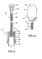
- Figs. 3a and 3b are partly cross-sectional views showing a practical embodiment of the antenna shown in Fig. 1, in which Fig. 3a shows how a first antenna portion shown in Fig. 1 is connected to a second antenna portion extended from a casing for communications, and Fig. 3b shows how the first antenna portion shown in Fig.1 is disconnected from the second antenna portion retracted into the casing for standby to receive a call signal;
- Fig. 4a is a perspective view showing a bobbin shown in Fig. 3a; and Fig. 4b is a perspective view showing the first antenna portion shown in Fig. 3a; and Fig. 4c is a development view showing the same first antenna portion shown in Fig. 4b;
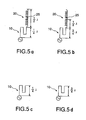
- Fig. 5a is an illustration showing the electrical length relationship between the first and second antenna portions, obtained when the second antenna portion is extended in 900 MHz band;
- Fig. 5b is an illustration showing the electrical length relationship between the first and second antenna portions, obtained when the second antenna portion is extended in 1800 MHz band;
- Fig. 5c is an illustration showing the electrical length relationship between the first and second antenna portions, obtained when the second antenna portion is retracted in 900 MHz band;
- Fig. 5d is an illustration showing the electrical length relationship between the first and second antenna portions, obtained when the second antenna portion is retracted in 1800 MHz band;
- Figs. 6a, 6b and 6c are illustrations showing another modification (top coil type) of the antenna shown in Fig. 1, in which Fig. 6a shows the case where the first and second antenna portions are connected directly; Fig. 6b shows the case where the first and second antenna portions are electrically coupled capacitively and/or inductively; and Fig. 6c shows the case where the first and second antenna portions are disconnected electrically by an insulation substance.
- The antenna according to the present invention will be described hereinbelow with reference to the attached drawings.
- The embodiment (i.e., a basic structure) of the antenna according to the present invention will be described hereinbelow with reference to Fig. 1. In Fig. 1, an antenna element 1 is formed by a copper wire, a piano wire, a belt-shaped conductive plate or a long conductor (e.g., a thin film). One end of the antenna element 1 is connected to a
feeder portion 3a of aconnector 3 via a casing 2 of a portable apparatus, and thefeeder portion 3a is connected to a transmit and/or receive circuit (not shown) through acord 4. As shown in Fig. 1, the antenna of the present invention is characterized in that the antenna element 1 has two portions la folded back alternatingly so as to extend substantially in parallel to each other along the longitudinal direction thereof. - As already explained, the inventors have found that when the antenna element is folded so that all portions are substantially parallel to each other along the longitudinal direction of the antenna element, the antenna element can be resonated at frequency bands being an even-number times (other than the odd-number times) higher than a low frequency band. In more detail, when the antenna element 1 formed so as to have a length of about 1/4 wavelength of a frequency band f1 and is formed with the folded back
portions 1a as shown in Fig. 1, the electrical length does not much change for the frequency band f1 and for the frequency bands being an odd-number times higher than the frequency f1 due to the capacitive coupling between the two adjacent antenna element portions and the relationship between the even propagation mode and odd propagation mode of the antenna element 1; however, the electrical length can be adjusted for the frequency bands being an even-number (e.g., two) times higher than the frequency f1 and the frequency bands in the vicinity of the higher frequency bands, by adjusting the number of folded back portions and the intervals between the two folded back antenna element portions. - With reference to Fig. 1, the basic construction of the antenna according to the present invention will be explained in further detail hereinbelow. The antenna element 1 is formed in such a way that the total length (A+B+C) (a and b are very short and thereby negligible) obtained by extending the antenna in the longitudinal direction is about (the same meaning as "substantially") 1/4 wavelength of the first frequency band f1 (the lowest frequency band of the signals to be transmitted and received). In an example shown in Fig. 1, two folded back
portions 1a are formed in the antenna element 1, so that the antenna element 1 is folded in three. The respective longitudinal lengths A, B and C of the portions of the antenna element folded in three are roughly equal to each other, and the intervals a and b between the two adjacent element portions are so adjusted as to be resonated at a frequency band f2 (=2f1) twice as high as the frequency band f1. The intervals a and b are roughly the same, but small as compared with the longitudinal length A, B and C, thus their lengths are short enough to be disregarded. - That is, the electrical length of the antenna element 1 can be set to about 3/4 wavelength of the frequency band f2 (=2f1) by adjusting the intervals a and b and the number of folded back portions, without much changing the electrical length for the frequency band f1. This may be due to the fact that the matching condition with the 1/4 wavelength of the frequency f1 (e.g., 900 MHz) and a frequency band being an odd-number times higher than f1 can be maintained without being subjected to the influence of the folded back portions of the antenna element; however, the electrical length of the frequency band being an even number times higher than f1 or the frequency band in the vicinity of the higher frequency bands can be changed on the basis of the capacity between the two adjacent antenna element portions and the current direction relationship between the even mode and the odd mode. As a result, this antenna can transmit and receive the signals of the frequency bands both being an odd-number and even-number times higher than f1. Further, it is also possible to resonate the antenna at an intermediate frequency band other than the frequency being an even-number times higher than f1 by adjusting the intervals between and the number of the antenna element portions.
- Since the antenna element is folded back in three, when the antenna element is molded by a protective casing formed of a resin, the total external length L of the antenna can be reduced to about 1/4 or 1/3 wavelength of f1, with the result that the total length thereof can be reduced as short as about 3cm in the case of a 900MHz frequency band. When the number of folded back portions is further increased, it is possible to further reduce the total length of the antenna.
- However, it is not preferable to increase the number of folded back
portions 1a excessively, because the capacity between the two adjacent element portions increases. Therefore, the preferable number of folded back portions is less than ten, and more preferably 2 to 6. Further, in particular, it is preferable that the number of the element portions is an odd number; that is, the number of the folded backportions 1a is an even number, because the polarized wave plane can be uniformalized. Further, it is preferable that the intervals a and b between the two adjacent antenna element portions is 1 to 5 mm when f1 is of a 900 MHz frequency band. - Further, the antenna element 1 can be folded back by a wire (e.g., copper wire, piano wire, etc.) or by a belt-shaped member (thin and broad) as shown in Fig. 1. Here, the belt-shaped member can be formed by punching a metal plate or by etching a thin film formed in accordance with vapor deposition. Further, the belt-shaped member can be simply formed at an end of a printed circuit board. Further, the antenna element portions can be fixed by molding the entire antenna element after having been adjusted. Here, even if the total physical length of the antenna element 1 (i.e., A+B+C) is substantially 1/2 wavelength of the frequency band f1 (not substantially 1/4 wavelength of f1), the antenna thus constructed can be resonated at a frequency band f1. Further, when a matching circuit is attached to the feeder portion, it is possible to transmit and receive radio signals by use of the antenna. In this case, the electrical length thereof is adjusted at the folded back
portions 1a so as to be one or 3/2 wavelength of a frequency band f2 twice as high as f1. - Further, the antenna element 1 can be folded back along the same direction and in the same plane as shown in Fig. 1. Without being limited thereto, the antenna element 1 can be folded back in such a way that the third element portion (whose length is C in Fig. 1) is turned so as to be located on the front side of the paper in close vicinity and in parallel to the other element portions in three dimensions. In summary, the essential point is that the direction in which the antenna element 1 is folded back is substantially in parallel to the longitudinal direction of the antenna element 1.
- As described above, since the antenna of the present invention is folded back along the longitudinal direction thereof, as far as the longitudinal direction of the antenna element is kept constant in the polarized wave plane of electromagnetic waves and further the electrical length thereof is so adjusted as to be the odd-number times of about 1/4 wavelength of the electromagnetic waves, it is possible to shorten the total external length L thereof, without reducing the antenna performance, even if any matching circuit is not attached thereto.
- Here, in order to further shorten the total external length of the antenna element 1, the antenna element portions can be formed into a zigzag or coil shape, as shown in Figs. 2a, 2b and 2c, respectively to such an extent that the antenna performance does not deteriorate. In more detail, in the case shown in Fig. 2a, the antenna element 1 is formed of folded back element portions each formed into a zigzag shape in the longitudinal direction of the antenna; and in the case shown in Fig. 2b, the antenna element 1 is of folded back element portions each formed into a coiled pattern in the longitudinal direction of the antenna. Further, in the case shown in Fig. 2c, the antenna element 1 is formed by winding each of the folded back antenna element portions as shown in Fig. 1 into a coil shape coarsely or loosely. In any of these examples, the total external antenna length can be shortened by forming a zigzag or coiled shape to such an extent as not to exert a harmful influence upon the antenna radiation characteristics.
- With reference to Figs. 3a and 3b and Figs. 4a, 4b and 4c, the antenna of the present invention will be described in detail hereinbelow in the form of a practical antenna suitable for use with a portable apparatus (e.g., a portable telephone set).
- Figs. 3a and 3b are cross-sectional views showing the practical antenna used for a portable telephone set, in which Fig. 3a shows the status where the antenna is extended for communications and Fig. 3b shows the status where the antenna is retracted for standby. In Figs. 3a and 3b, a
first antenna portion 10 is always kept exposed externally from a casing of the portable apparatus to receive a call signal, and asecond antenna portion 20 is extended from the casing of the portable apparatus to increase the sensitivity only during communications. - The
first antenna portion 10 is composed of a cylindrical bobbin 11 (as shown in Fig. 4a) formed of PE (polyethylene) or POM (polyoxymethylene), and a first antenna element 12 (as shown in Fig. 4b) pressure fitted to the outer circumference of thecylindrical bobbin 11 by an elastic force of the material of thefirst antenna element 12. Thefirst antenna element 12 is formed into a cylindrical shape by punching a plate spring formed of phosphor bronze or beryllium copper with the use of a press machine in such a way that the total length thereof in the longitudinal direction is substantially 1/4 wavelength of a 900 MHz frequency band, for instance. Further, one (lower)end 12a of thefirst antenna element 12 is formed into a ring shape as shown in Fig. 4b. Thisend 12a of thefirst antenna element 12 is pressure fitted into an inner circumference of a mountingfixture 13 together with thebobbin 11 in such a way as to be connected to the mountingfixture 13 electrically, as shown in Fig. 3a. The other (upper) end of thefirst antenna element 12 is formed with a projectingportion 12b as shown in Fig. 4b. This projectingportion 12b is engaged with arecess 23a formed in an (lower) end of thesecond antenna portion 20 as a locking spring in such a way as to be fixed and connected to thesecond antenna portion 20 electrically. When developed as shown in Fig. 4c, thefirst antenna element 12 is formed with seven element pieces and six folded backportions 12c. However, thefirst antenna element 12 can be formed with three element pieces and two folded back portions as shown in Fig. 1. Further, the mountingfixture 13 of thefirst antenna portion 10 is formed with a threadedportion 13a, as shown in Fig. 3a, engaged with a threaded portion (not shown) formed in the casing of the portable telephone set. Further, in Fig. 3a, acover 14 formed of ABS (acrylic butadiene styrene), elastomer, etc. is screwed with an upper threaded portion of the mountingfixture 13 to protect thefirst antenna element 12. - The
second antenna portion 20 is used during communications after having been extended to the outside from the casing, which is formed by winding a piano wire or copper wire having substantially 1/2 wavelength of 900 MHz band into a coil shape. Further, thesecond antenna portion 20 is protected at the outer circumference thereof by atube 22 formed of POM, elastomer, et al. in such a way as to be movable in thebobbin 11 of thefirst antenna portion 10. Thesecond antenna element 21 is formed with atrap 25 at an intermediate portion thereof in such a way that the continuous total length thereof functions in the 900 MHz band and a lower half below thetrap 25 functions in the 1800 MHz band. Further, astopper 23 formed of brass or PBS (phosphor bronze) is electrically connected to the lower end of thesecond antenna element 21 at the lower end of thesecond antenna portion 20 by a thread engagement with thetube 22 of thesecond antenna portion 20. Further, a top 24 formed of ABS, elastomer, et al. is screwed with the upper end of thesecond antenna portion 20 as a knob used when thesecond antenna portion 20 is pulled outside from the casing. This top 24 can be formed integral with thetube 22 of thesecond antenna portion 20 if desired. - Further, the
stopper 23 is formed with therecess 23a in the outer circumference thereof in such a way as to be engaged with the projectingportion 12b of thefirst antenna element 12 for electric contact therewith, when thesecond antenna portion 20 is pulled out of the casing. Therefore, when thesecond antenna portion 20 is extended, thefirst antenna element 12 is connected to thesecond antenna element 21 via themetal stopper 23, and thereby can function as an antenna having substantially 3/4 wavelength of the 900 MHz band signals, so that the antenna can be resonated at 900 MHz band signals to transmit and receive the signals. Further, since thefirst antenna portion 10 has an electrical length of substantially 3/4 wavelength of the 1800 MHz band signals, and further since the lower half of thesecond antenna portion 20 below thetrap 25 has an electrical length of substantially 1/2 wavelength thereof, the antenna can be resonated at 1800 MHz band signal to transmit and receive the signals in the same way. - Further, the top 24 of the
second antenna portion 20 is formed with arecess 24a in the outer circumference of the lower portion thereof. Therefore, when thesecond antenna portion 20 is retracted and thereby housed in the casing, since the top 24 is inserted into the upper portion of thebobbin 11, therecess 24a of the top 24 is engaged with the projectingportion 12b of thefirst antenna element 12, so that the top 24 can be securely fixed to thebobbin 11. Here, since the top 24 is formed of a resin and therefore insulated electrically, thesecond antenna portion 20 housed in the casing is perfectly isolated electrically, and thereby does not function as an antenna. As a result, only thefirst antenna portion 10 can function as an antenna for receiving a call signal. Further, in a region where the radio waves are sufficiently strong, thefirst antenna portion 10 can of course receive radio signals not only for a call signal but also for communications. - Figs. 5a and 5b show the electrical lengths for 900 MHz and 1800 MHz, respectively obtained when the
second antenna portion 20 is extended for communications; and Figs. 5c and 5d show the electrical lengths for 900 MHz and 1800 MHz, respectively obtained when thesecond antenna portion 20 is retracted and only thefirst antenna portion 10 is used for standby, in which the electrical length is denoted on the basis of the wavelength of λ. In the case of 900 MHz, the electrical length of thefirst antenna portion 10 is λ/4 thereof; and the electrical length of thesecond antenna portion 20 is λ/2 thereof. On the other hand, in the case of 1800 MHz, the electrical length of thefirst antenna portion 10 is 3/4; and the electrical length of thesecond antenna portion 20 is divided to λ/2 by atrap 25 provided midway of thesecond antenna portion 20. Therefore, thesecond antenna portion 20 can function as an antenna having about λ/2 wavelength in the 1800 MHz band. - In the example shown in Fig. 3a, the first and
second antenna portions second antenna portions stopper 23 is formed of an electrically insulating material, without use of a metal. - Figs. 6a, 6b and 6c show an example of a top coil type, in which the
first antenna portion 10 is located on the upper portion of thesecond antenna portion 20. In more detail, in thefirst antenna portion 10, an end of thefirst antenna element 15 of the present invention in which the folded back portions are formed is connected to ametal fixture 16. Therefore, when thesecond antenna portion 20 is retracted into the casing, themetal fixture 16 is connected to the feeder portion of the casing. Further, in thesecond antenna portion 20, astopper 26 is attached to one end of thesecond antenna element 25a. Therefore, when thesecond antenna portion 20 is extended from the casing, thisstopper 26 is connected to the feeder portion of the casing. The length of thefirst antenna element 15 is normally set to a substantially 1/4 wavelength of the first frequency band f1 (e.g., 900 MHz), and the length of thesecond antenna element 25a is normally set to a substantially 1/2 wavelength of the first frequency band f1 (e.g., 900 MHz). However, it is also possible to set the substantial length of thesecond antenna element 25a to a substantially 1/4 wavelength of the first frequency band f1 by providing a matching circuit on the casing side. Further, in the example shown in Fig. 6a, themetal fixture 16 of thefirst antenna portion 10 is directly connected to the upper end of thesecond antenna portion 20 electrically; and in the example shown in Fig. 6b, themetal fixture 16 of thefirst antenna portion 10 is fixed to the upper end of thesecond antenna portion 20 by use of an electrically insulatingmaterial 18, and coupled to each other electrically by a capacitive or inductive coupling. Further, in Figs. 6a and 6b, a top 17 formed of a resin is attached to thefirst antenna element 15 for covering it. - Fig. 6c is a diagram showing an example of the antenna according to the present invention, in which the
second antenna element 25a is also formed with the folded back portions. Further, in Fig. 6c, although the first andsecond antenna portions substance 18, it is of course possible to connect both the antenna portions electrically by a mechanical direct contact between both. Further, when the first andsecond antenna portions second antenna elements second antenna element 25a and to increase the external dimension thereof. In this case, when thesecond antenna portion 20 is pulled out of the casing, only the extendedsecond antenna portion 20 can function as an antenna which can increase the sensitivity during communications, as compared with when only thefirst antenna portion 10 is used. In this case, it is possible to transmit and receive radio signals in plural frequency bands, while reducing the antenna length. - In the case of a radio apparatus such as a portable telephone set, it is preferable that a multi-frequency band can be transmitted and received by use of a small-sized antenna. When the antenna according to the present invention as described above is used, it is possible to obtain a small-sized radio apparatus, which is convenient when the apparatus is being carried and which can transmit and receive multi-frequency bands. In other words, in the radio apparatus, the transmit and receive circuit is housed in the casing, and the antenna is connected to the transmit and receive circuit electrically via a feeder portion disposed in the casing. Therefore, when the antenna according to the present invention as shown in Figs. 3a to 6c is connected to the casing as it is, it is possible to obtain a radio apparatus according to the present invention. Further, without being limited only to the antenna as shown in Figs. 3a to 6c, when the antenna as shown in Fig. 1 is used as the whole or a part of the antenna of the radio apparatus, it is possible to obtain a small-sized radio apparatus which can transmit and receive multi-frequency bands at a high sensitivity.
- As described above, in the antenna according to the present invention, since the antenna element of a long conductor is formed of portions folded back so as to extend in parallel to the longitudinal direction of the antenna, it is possible to shorten the total external physical length of the antenna without deteriorating the radiation characteristics of the antenna.
- Further, since the antenna can be resonated at the frequency bands being even- or odd-times higher than a frequency band or in the vicinity of the higher frequency bands on the basis of the capacitive coupling and mutual function of the adjacent folded back antenna element portions, it is possible to transmit and receive multi-frequency band signals by use of a single antenna element, without connecting plural antenna elements for two or more frequency bands (other than the odd-number frequency bands) via a trap or traps.
- Further, in the antenna suitable for use with a portable apparatus according to the present invention, the size of the antenna for receiving only a call signal can be reduced markedly, without deteriorating the antenna performance. Further, when the antenna element is formed by a belt-shaped member, it is possible to obtain an antenna simple in manufacturing process, small in size, and high in antenna characteristics.
Claims (4)
- An antenna comprising:an antenna element (1; 12; 15; 25a) formed by a long conductor and formed with at least one folded back portion (la) arranged substantially in parallel to a longitudinal direction of the antenna element,
said antenna element being formed to resonate substantially in total length with one-fourth wave length of a second frequency band, and
said folded back portion being formed to resonate substantially with three-fourths wave length of a second frequency band which is double that of the first frequency band. - An antenna according to Claim 1, wherein said antenna element (12) is formed at the outer periphery of a cylindrical body (11) made of an electrical insulator.
- An antenna according to Claim 1, wherein an end of said antenna element (12) comprises a ring portion (12a) extending in circumferential direction of said cylindrical body (11).
- An antenna according to Claim 1, said long conductor being formed in zigzag shape.
Applications Claiming Priority (6)
| Application Number | Priority Date | Filing Date | Title |
|---|---|---|---|
| JP8160016A JP2898921B2 (en) | 1996-06-20 | 1996-06-20 | Antennas and radios |
| JP21254096A JP3180034B2 (en) | 1996-08-12 | 1996-08-12 | antenna |
| JP21254296A JP3160534B2 (en) | 1996-08-12 | 1996-08-12 | antenna |
| JP21254196A JP3195742B2 (en) | 1996-08-12 | 1996-08-12 | antenna |
| EP03012659A EP1345283A1 (en) | 1996-06-20 | 1996-11-23 | Antenna |
| EP96118810A EP0814536A3 (en) | 1996-06-20 | 1996-11-23 | Antenna and radio apparatus using same |
Related Parent Applications (1)
| Application Number | Title | Priority Date | Filing Date |
|---|---|---|---|
| EP03012659A Division EP1345283A1 (en) | 1996-06-20 | 1996-11-23 | Antenna |
Publications (1)
| Publication Number | Publication Date |
|---|---|
| EP1641070A1 true EP1641070A1 (en) | 2006-03-29 |
Family
ID=27473647
Family Applications (4)
| Application Number | Title | Priority Date | Filing Date |
|---|---|---|---|
| EP96118810A Withdrawn EP0814536A3 (en) | 1996-06-20 | 1996-11-23 | Antenna and radio apparatus using same |
| EP05025307A Withdrawn EP1641070A1 (en) | 1996-06-20 | 1996-11-23 | Antenna |
| EP02011240A Ceased EP1239537A3 (en) | 1996-06-20 | 1996-11-23 | Retractable antenna for a portable radio apparatus |
| EP03012659A Ceased EP1345283A1 (en) | 1996-06-20 | 1996-11-23 | Antenna |
Family Applications Before (1)
| Application Number | Title | Priority Date | Filing Date |
|---|---|---|---|
| EP96118810A Withdrawn EP0814536A3 (en) | 1996-06-20 | 1996-11-23 | Antenna and radio apparatus using same |
Family Applications After (2)
| Application Number | Title | Priority Date | Filing Date |
|---|---|---|---|
| EP02011240A Ceased EP1239537A3 (en) | 1996-06-20 | 1996-11-23 | Retractable antenna for a portable radio apparatus |
| EP03012659A Ceased EP1345283A1 (en) | 1996-06-20 | 1996-11-23 | Antenna |
Country Status (3)
| Country | Link |
|---|---|
| US (1) | US5995064A (en) |
| EP (4) | EP0814536A3 (en) |
| CN (1) | CN1103126C (en) |
Families Citing this family (89)
| Publication number | Priority date | Publication date | Assignee | Title |
|---|---|---|---|---|
| US6111545A (en) * | 1992-01-23 | 2000-08-29 | Nokia Mobile Phones, Ltd. | Antenna |
| JP2000223928A (en) * | 1999-01-28 | 2000-08-11 | Smk Corp | Antenna system |
| US20060119525A1 (en) * | 2004-08-24 | 2006-06-08 | Nathan Cohen | Wideband antenna system for garments |
| US20050231426A1 (en) * | 2004-02-02 | 2005-10-20 | Nathan Cohen | Transparent wideband antenna system |
| US7019695B2 (en) | 1997-11-07 | 2006-03-28 | Nathan Cohen | Fractal antenna ground counterpoise, ground planes, and loading elements and microstrip patch antennas with fractal structure |
| US6452553B1 (en) * | 1995-08-09 | 2002-09-17 | Fractal Antenna Systems, Inc. | Fractal antennas and fractal resonators |
| US5955997A (en) * | 1996-05-03 | 1999-09-21 | Garmin Corporation | Microstrip-fed cylindrical slot antenna |
| EP0863571B1 (en) * | 1997-03-05 | 2006-04-12 | Murata Manufacturing Co., Ltd. | A mobile image apparatus and an antenna apparatus used for the mobile image apparatus |
| WO1999022462A1 (en) * | 1997-10-27 | 1999-05-06 | Siemens Aktiengesellschaft | Method, mobile station and base station for establishing connections in a radiocommunications system |
| US6445352B1 (en) * | 1997-11-22 | 2002-09-03 | Fractal Antenna Systems, Inc. | Cylindrical conformable antenna on a planar substrate |
| US6229489B1 (en) * | 1998-02-11 | 2001-05-08 | Ericsson Inc. | Retractable dual-band antenna system with parallel resonant trap |
| FI980392A (en) * | 1998-02-20 | 1999-08-21 | Nokia Mobile Phones Ltd | Antenna |
| EP0954054A1 (en) * | 1998-04-30 | 1999-11-03 | Kabushiki Kaisha Yokowo | Folded antenna |
| JP2000004112A (en) * | 1998-06-15 | 2000-01-07 | Matsushita Electric Ind Co Ltd | Antenna |
| US6031505A (en) * | 1998-06-26 | 2000-02-29 | Research In Motion Limited | Dual embedded antenna for an RF data communications device |
| EP0973228A1 (en) * | 1998-07-16 | 2000-01-19 | Koninklijke Philips Electronics N.V. | RF equipment with a rod antenna |
| EP1114490A2 (en) | 1998-09-16 | 2001-07-11 | Siemens Aktiengesellschaft | Antenna which can be operated in several frequency bands |
| JP2001036337A (en) * | 1999-03-05 | 2001-02-09 | Matsushita Electric Ind Co Ltd | Antenna system |
| JP3395696B2 (en) | 1999-03-15 | 2003-04-14 | 日本電気株式会社 | Wafer processing apparatus and wafer processing method |
| WO2000060697A1 (en) * | 1999-04-06 | 2000-10-12 | Mitsubishi Denki Kabushiki Kaisha | Method of manufacturing cellular radio device and case |
| FR2794574A1 (en) * | 1999-06-02 | 2000-12-08 | Socapex Amphenol | Retractable dual band antenna for mobile phones has moveable whip and two helical antennas with different winding pitches |
| JP4012733B2 (en) | 1999-09-20 | 2007-11-21 | フラクトゥス・ソシエダッド・アノニマ | Multi-level antenna |
| ATE248443T1 (en) | 1999-10-26 | 2003-09-15 | Fractus Sa | NESTED MULTI-BAND GROUP ANTENNAS |
| DE19961488A1 (en) * | 1999-12-20 | 2001-06-21 | Siemens Ag | Antenna for communications terminal has a relatively large bandwidth and can be manufactured cheaply and reproducibly |
| KR20000049358A (en) * | 1999-12-20 | 2000-08-05 | 장응순 | The antenna for mobile communication terminal |
| EP1592083B1 (en) | 2000-01-19 | 2013-04-03 | Fractus, S.A. | Space-filling miniature antennas |
| US7245196B1 (en) | 2000-01-19 | 2007-07-17 | Fractus, S.A. | Fractal and space-filling transmission lines, resonators, filters and passive network elements |
| SE516485C2 (en) * | 2000-02-18 | 2002-01-22 | Allgon Ab | A contact device comprising a first radiating element integral thereof, an antenna device comprising such a contact device, and a handheld radio communication device comprising said antenna device. |
| US6329951B1 (en) | 2000-04-05 | 2001-12-11 | Research In Motion Limited | Electrically connected multi-feed antenna system |
| JP3492613B2 (en) * | 2000-04-14 | 2004-02-03 | 埼玉日本電気株式会社 | Antenna for portable radio |
| ATE378700T1 (en) | 2000-04-19 | 2007-11-15 | Advanced Automotive Antennas S | ADVANCED MULTI-PLANE ANTENNA FOR MOTOR VEHICLES |
| WO2001093368A1 (en) * | 2000-06-01 | 2001-12-06 | Mitsubishi Denki Kabushiki Kaisha | Antenna element and portable information terminal |
| SE522846C2 (en) * | 2000-06-22 | 2004-03-09 | Ericsson Telefon Ab L M | Antenna with helical radiator and feedback conductor, as well as multi-layer cards and portable communication apparatus including such an antenna |
| KR100856597B1 (en) | 2000-10-12 | 2008-09-03 | 후루까와덴끼고오교 가부시끼가이샤 | Small antenna |
| US6486839B1 (en) * | 2000-10-20 | 2002-11-26 | Jerry B. Minter | Relative elevation detection for aircraft pilot warning system |
| JP3455727B2 (en) * | 2001-01-04 | 2003-10-14 | 株式会社東芝 | Antennas and wireless terminals using them |
| US6674405B2 (en) | 2001-02-15 | 2004-01-06 | Benq Corporation | Dual-band meandering-line antenna |
| CA2381043C (en) | 2001-04-12 | 2005-08-23 | Research In Motion Limited | Multiple-element antenna |
| TW538559B (en) * | 2001-07-18 | 2003-06-21 | Matsushita Electric Ind Co Ltd | Antenna device and mobile communications apparatus including the device |
| US9755314B2 (en) | 2001-10-16 | 2017-09-05 | Fractus S.A. | Loaded antenna |
| EP1942551A1 (en) | 2001-10-16 | 2008-07-09 | Fractus, S.A. | Multiband antenna |
| ES2190749B1 (en) | 2001-11-30 | 2004-06-16 | Fractus, S.A | "CHAFF" MULTINIVEL AND / OR "SPACE-FILLING" DISPERSORS, AGAINST RADAR. |
| DE60329793D1 (en) | 2002-06-21 | 2009-12-03 | Research In Motion Ltd | Multiple element antenna with parasitic coupler |
| JP3921425B2 (en) * | 2002-07-19 | 2007-05-30 | 株式会社ヨコオ | Surface mount antenna and portable radio |
| KR100548986B1 (en) * | 2002-11-13 | 2006-02-03 | 장응순 | Folded Monopole Antenna |
| KR20030024646A (en) * | 2002-11-14 | 2003-03-26 | 장응순 | Folded Monopole Intenna |
| US6791500B2 (en) | 2002-12-12 | 2004-09-14 | Research In Motion Limited | Antenna with near-field radiation control |
| US6812897B2 (en) | 2002-12-17 | 2004-11-02 | Research In Motion Limited | Dual mode antenna system for radio transceiver |
| FI115173B (en) * | 2002-12-31 | 2005-03-15 | Filtronic Lk Oy | Antenna for a collapsible radio |
| EP1597794B1 (en) | 2003-02-19 | 2008-08-20 | Fractus S.A. | Miniature antenna having a volumetric structure |
| JP4348993B2 (en) * | 2003-04-24 | 2009-10-21 | アイシン精機株式会社 | Electrical component and manufacturing method thereof |
| EP1478047B1 (en) | 2003-05-14 | 2007-10-03 | Research In Motion Limited | Antenna with multiple-band patch and slot structures |
| EP1912279B1 (en) | 2003-06-12 | 2011-01-05 | Research In Motion Limited | Multiple-element antenna with electromagnetically coupled floating antenna element |
| US6980173B2 (en) | 2003-07-24 | 2005-12-27 | Research In Motion Limited | Floating conductor pad for antenna performance stabilization and noise reduction |
| US7250917B1 (en) | 2004-01-14 | 2007-07-31 | Thompson Louis H | Directional wire antennas for radio frequency identification tag system |
| US7369089B2 (en) | 2004-05-13 | 2008-05-06 | Research In Motion Limited | Antenna with multiple-band patch and slot structures |
| US7153495B2 (en) * | 2004-06-10 | 2006-12-26 | Reheis, Inc. | Fragrance friendly and cost effective antiperspirant actives and method of making the same |
| US7908080B2 (en) | 2004-12-31 | 2011-03-15 | Google Inc. | Transportation routing |
| JP4308786B2 (en) * | 2005-02-24 | 2009-08-05 | パナソニック株式会社 | Portable radio |
| JP2007060617A (en) * | 2005-07-28 | 2007-03-08 | Mitsumi Electric Co Ltd | Antenna device |
| DE102006006144A1 (en) * | 2006-02-10 | 2007-08-23 | Lumberg Connect Gmbh | dipole antenna |
| US8738103B2 (en) | 2006-07-18 | 2014-05-27 | Fractus, S.A. | Multiple-body-configuration multimedia and smartphone multifunction wireless devices |
| DE102006049485A1 (en) * | 2006-10-17 | 2008-04-24 | Tyco Electronics Belgium Ec N.V. | End cap for an inductive component and inductive component |
| US8692725B2 (en) | 2007-12-20 | 2014-04-08 | Harada Industry Co., Ltd. | Patch antenna device |
| CN101217213B (en) * | 2007-12-26 | 2012-05-23 | 蒋小平 | An upper laid aerial device of automobile |
| EP2230993B1 (en) | 2008-01-15 | 2018-08-15 | Cardiac Pacemakers, Inc. | Implantable medical device with antenna |
| EP2265331B1 (en) | 2008-03-28 | 2016-03-23 | Cochlear Limited | Antenna for behind-the-ear (bte) devices |
| JP4524318B2 (en) * | 2008-05-27 | 2010-08-18 | 原田工業株式会社 | Automotive noise filter |
| JP5114325B2 (en) * | 2008-07-08 | 2013-01-09 | 原田工業株式会社 | Roof mount antenna device for vehicle |
| US8059060B2 (en) * | 2008-09-08 | 2011-11-15 | I-5 Wireless, LLC. | Unitary solderless monopole antenna for in-duct use |
| JP4832549B2 (en) * | 2009-04-30 | 2011-12-07 | 原田工業株式会社 | Vehicle antenna apparatus using space filling curve |
| EP2486624B1 (en) * | 2009-10-05 | 2015-03-25 | Cardiac Pacemakers, Inc. | Multi-band antenna for implantable device |
| JP4955094B2 (en) * | 2009-11-02 | 2012-06-20 | 原田工業株式会社 | Patch antenna |
| US8559869B2 (en) | 2011-09-21 | 2013-10-15 | Daniel R. Ash, JR. | Smart channel selective repeater |
| GB2504397B (en) | 2011-01-12 | 2014-10-01 | Harada Ind Co Ltd | Helical vehicle fin antenna arrangement |
| JP5274597B2 (en) | 2011-02-15 | 2013-08-28 | 原田工業株式会社 | Vehicle pole antenna |
| JP5654917B2 (en) | 2011-03-24 | 2015-01-14 | 原田工業株式会社 | Antenna device |
| CN102732437B (en) * | 2012-06-04 | 2013-10-23 | 中国科学院微生物研究所 | Saccharomyces cerevisiae engineering bacterium and its application in production of ethanol |
| USD726696S1 (en) | 2012-09-12 | 2015-04-14 | Harada Industry Co., Ltd. | Vehicle antenna |
| ITBO20120603A1 (en) * | 2012-11-06 | 2014-05-07 | Clarbruno Vedruccio | NVIS VERTICAL ANTENNA RECORDED FOR SHORT-WAVE TACTICAL TRANSCEIVERS |
| US8954122B2 (en) * | 2013-07-03 | 2015-02-10 | BluFlux RF Technologies, LLC | Electronic device case with antenna |
| DE102015111767A1 (en) * | 2014-07-18 | 2016-01-21 | Huf Hülsbeck & Fürst Gmbh & Co. Kg | Door interior handle system for a door of a vehicle |
| US10654365B2 (en) * | 2015-04-29 | 2020-05-19 | Aptiv Technologies Limited | Bifurcated balanced electromagnetic resonator |
| WO2018126247A2 (en) | 2017-01-02 | 2018-07-05 | Mojoose, Inc. | Automatic signal strength indicator and automatic antenna switch |
| CN107516762B (en) * | 2017-07-31 | 2019-12-13 | 维沃移动通信有限公司 | Antenna structure and mobile terminal |
| US20200209928A1 (en) * | 2018-12-27 | 2020-07-02 | Innolux Corporation | Electronic device |
| DE112021001088T5 (en) * | 2020-04-22 | 2023-01-12 | AGC Inc. | ANTENNA DEVICE |
| TWI760197B (en) * | 2021-04-27 | 2022-04-01 | 和碩聯合科技股份有限公司 | Antenna module |
| US11454662B1 (en) * | 2021-09-10 | 2022-09-27 | Litepoint Corporation | System and method for over-the-air (OTA) testing to detect faulty elements in an active array antenna of an extremely high frequency (EHF) wireless communication device |
Citations (4)
| Publication number | Priority date | Publication date | Assignee | Title |
|---|---|---|---|---|
| US1957949A (en) * | 1928-07-17 | 1934-05-08 | Rca Corp | Antenna |
| GB581567A (en) * | 1941-11-03 | 1946-10-17 | Internat Marine Radio Company | Improvements relating to transmitting aerials |
| US2647211A (en) * | 1949-01-11 | 1953-07-28 | Lynne C Smeby | Radio antenna |
| JPH057109A (en) * | 1991-06-27 | 1993-01-14 | Mitsubishi Electric Corp | Built-in antenna for portable telephone set |
Family Cites Families (33)
| Publication number | Priority date | Publication date | Assignee | Title |
|---|---|---|---|---|
| US2821710A (en) * | 1954-08-06 | 1958-01-28 | George H Ferriman | Television antenna |
| JPS5525689B2 (en) * | 1974-09-19 | 1980-07-08 | ||
| US4121218A (en) * | 1977-08-03 | 1978-10-17 | Motorola, Inc. | Adjustable antenna arrangement for a portable radio |
| JPS5794930A (en) * | 1980-12-03 | 1982-06-12 | Fujitsu Ltd | Surface lubricating method for magnetic recording medium |
| US4604628A (en) * | 1983-03-11 | 1986-08-05 | Telex Communications, Inc. | Parasitic array with driven sleeve element |
| KR900009111B1 (en) * | 1986-11-07 | 1990-12-22 | 야기 안테나 가부시기가이샤 | Antenna devices of film |
| CN87211386U (en) * | 1987-11-16 | 1988-08-24 | 上海市东海军工技术工程公司 | Fully frequency channel planar tv receiving antenna |
| US4868576A (en) * | 1988-11-02 | 1989-09-19 | Motorola, Inc. | Extendable antenna for portable cellular telephones with ground radiator |
| GB2237449B (en) * | 1989-09-30 | 1994-03-30 | Hi Trak Systems Ltd | Transmitter and antenna |
| US5363114A (en) * | 1990-01-29 | 1994-11-08 | Shoemaker Kevin O | Planar serpentine antennas |
| US5204687A (en) * | 1990-07-19 | 1993-04-20 | Galtronics Ltd. | Electrical device and electrical transmitter-receiver particularly useful in a ct2 cordless telephone |
| JP2510782B2 (en) * | 1990-11-28 | 1996-06-26 | 三菱電機株式会社 | Antenna device |
| JP3185322B2 (en) * | 1992-02-28 | 2001-07-09 | 株式会社日立製作所 | Small antenna for portable radio |
| US5517206A (en) * | 1991-07-30 | 1996-05-14 | Ball Corporation | Broad band antenna structure |
| AT396532B (en) * | 1991-12-11 | 1993-10-25 | Siemens Ag Oesterreich | ANTENNA ARRANGEMENT, ESPECIALLY FOR COMMUNICATION TERMINALS |
| SE501551C2 (en) * | 1992-10-29 | 1995-03-13 | Allgon Ab | Antenna device for portable equipment |
| JPH05347507A (en) * | 1992-06-12 | 1993-12-27 | Junkosha Co Ltd | Antenna |
| JPH0634309A (en) * | 1992-07-21 | 1994-02-08 | Norio Mori | Graphite structure distortion factor measuring sensor |
| JPH0690108A (en) * | 1992-09-07 | 1994-03-29 | Nippon Telegr & Teleph Corp <Ntt> | Compact antenna and manufacture of the same |
| JP2809365B2 (en) * | 1992-09-28 | 1998-10-08 | エヌ・ティ・ティ移動通信網株式会社 | Portable radio |
| KR960010858B1 (en) * | 1993-05-21 | 1996-08-10 | 삼성전자 주식회사 | Portable wireless-machine antenna |
| SE9301761L (en) * | 1993-05-24 | 1994-06-06 | Allgon Ab | Antenna device for portable communication equipment |
| EP0634806A1 (en) * | 1993-07-13 | 1995-01-18 | Kabushiki Kaisha Yokowo | Radio antenna |
| JPH0770896A (en) * | 1993-08-31 | 1995-03-14 | Koyo:Kk | Nonwoven cloth |
| US5469177A (en) * | 1993-09-15 | 1995-11-21 | Motorola, Inc. | Antenna assembly and method therefor |
| RU2152672C1 (en) * | 1993-09-20 | 2000-07-10 | Моторола Инк. | Antenna assembly for radio communication device |
| JPH07106994A (en) * | 1993-10-08 | 1995-04-21 | Hitachi Ltd | Portable radio equipment antenna |
| JPH07288412A (en) * | 1994-04-19 | 1995-10-31 | Kyocera Corp | Antenna |
| JPH07321527A (en) * | 1994-05-27 | 1995-12-08 | Antenna Giken Kk | Portable radio equipment |
| IL110008A (en) * | 1994-06-13 | 1998-04-05 | Galtronics Ltd | Electrical antenna assembly and electrical device including same |
| JP3045932B2 (en) * | 1994-07-12 | 2000-05-29 | 株式会社ヨコオ | antenna |
| US5561437A (en) * | 1994-09-15 | 1996-10-01 | Motorola, Inc. | Two position fold-over dipole antenna |
| SE509638C2 (en) * | 1996-06-15 | 1999-02-15 | Allgon Ab | Meander antenna device |
-
1996
- 1996-11-23 EP EP96118810A patent/EP0814536A3/en not_active Withdrawn
- 1996-11-23 EP EP05025307A patent/EP1641070A1/en not_active Withdrawn
- 1996-11-23 EP EP02011240A patent/EP1239537A3/en not_active Ceased
- 1996-11-23 EP EP03012659A patent/EP1345283A1/en not_active Ceased
- 1996-11-25 US US08/755,733 patent/US5995064A/en not_active Expired - Lifetime
- 1996-12-24 CN CN96117962A patent/CN1103126C/en not_active Expired - Fee Related
Patent Citations (4)
| Publication number | Priority date | Publication date | Assignee | Title |
|---|---|---|---|---|
| US1957949A (en) * | 1928-07-17 | 1934-05-08 | Rca Corp | Antenna |
| GB581567A (en) * | 1941-11-03 | 1946-10-17 | Internat Marine Radio Company | Improvements relating to transmitting aerials |
| US2647211A (en) * | 1949-01-11 | 1953-07-28 | Lynne C Smeby | Radio antenna |
| JPH057109A (en) * | 1991-06-27 | 1993-01-14 | Mitsubishi Electric Corp | Built-in antenna for portable telephone set |
Non-Patent Citations (2)
| Title |
|---|
| JALIL RASHED ET AL: "A NES CLASS OF RESONANT ANTENNAS", IEEE TRANSACTIONS ON ANTENNAS AND PROPAGATION, IEEE INC. NEW YORK, US, vol. 39, no. 9, 1 September 1991 (1991-09-01), pages 1428 - 1430, XP000232090, ISSN: 0018-926X * |
| PATENT ABSTRACTS OF JAPAN vol. 017, no. 264 (E - 1370) 24 May 1993 (1993-05-24) * |
Also Published As
| Publication number | Publication date |
|---|---|
| EP1239537A2 (en) | 2002-09-11 |
| CN1103126C (en) | 2003-03-12 |
| EP0814536A2 (en) | 1997-12-29 |
| EP0814536A3 (en) | 1999-10-13 |
| EP1345283A1 (en) | 2003-09-17 |
| US5995064A (en) | 1999-11-30 |
| CN1171641A (en) | 1998-01-28 |
| EP1239537A3 (en) | 2002-09-25 |
Similar Documents
| Publication | Publication Date | Title |
|---|---|---|
| EP1641070A1 (en) | Antenna | |
| EP0747990B1 (en) | Antenna | |
| US5541610A (en) | Antenna for a radio communication apparatus | |
| US5986616A (en) | Antenna system for circularly polarized radio waves including antenna means and interface network | |
| JP3835128B2 (en) | Antenna device | |
| US6218992B1 (en) | Compact, broadband inverted-F antennas with conductive elements and wireless communicators incorporating same | |
| JPH10173430A (en) | Dual frequency antenna | |
| US5691730A (en) | Retractable broad-band antenna for portable telephones | |
| US6011516A (en) | Multiband antenna with a distributed-constant dielectric resonant circuit as an LC parallel resonant circuit, and multiband portable radio apparatus using the multiband antenna | |
| EP1332535B1 (en) | Device by an antenna | |
| EP0718909B1 (en) | Retractable top load antenna | |
| JP2898921B2 (en) | Antennas and radios | |
| US7158819B1 (en) | Antenna apparatus with inner antenna and grounded outer helix antenna | |
| JP3195742B2 (en) | antenna | |
| US5969682A (en) | Antenna apparatus and portable radio apparatus | |
| US6008765A (en) | Retractable top load antenna | |
| KR20000068463A (en) | Coaxial dual-band antenna | |
| CA2291773C (en) | Antenna assembly and a mobile radio apparatus using the same | |
| EP1494314B1 (en) | Antenna device | |
| JP3180034B2 (en) | antenna | |
| JP3364417B2 (en) | Antenna for portable radio | |
| US5918162A (en) | Antenna unit and portable radio terminal with a feeding circuit and spiral antenna | |
| WO2008117898A1 (en) | Broad band antenna | |
| KR100644076B1 (en) | Dual band antenna | |
| JPH11234026A (en) | Dual-band antenna |
Legal Events
| Date | Code | Title | Description |
|---|---|---|---|
| PUAI | Public reference made under article 153(3) epc to a published international application that has entered the european phase |
Free format text: ORIGINAL CODE: 0009012 |
|
| AC | Divisional application: reference to earlier application |
Ref document number: 0814536 Country of ref document: EP Kind code of ref document: P Ref document number: 1345283 Country of ref document: EP Kind code of ref document: P |
|
| AK | Designated contracting states |
Kind code of ref document: A1 Designated state(s): AT BE CH DE DK ES FI FR GB GR IE IT LI LU MC NL PT SE |
|
| AX | Request for extension of the european patent |
Extension state: AL LT LV RO SI |
|
| AKX | Designation fees paid |
Designated state(s): DE FI FR GB SE |
|
| 17P | Request for examination filed |
Effective date: 20061005 |
|
| RBV | Designated contracting states (corrected) |
Designated state(s): AT BE CH DE DK FI FR GB LI SE |
|
| 17Q | First examination report despatched |
Effective date: 20070213 |
|
| STAA | Information on the status of an ep patent application or granted ep patent |
Free format text: STATUS: THE APPLICATION IS DEEMED TO BE WITHDRAWN |
|
| 18D | Application deemed to be withdrawn |
Effective date: 20070626 |