EP1640681A1 - Interior light socket and refigerator - Google Patents
Interior light socket and refigerator Download PDFInfo
- Publication number
- EP1640681A1 EP1640681A1 EP04746465A EP04746465A EP1640681A1 EP 1640681 A1 EP1640681 A1 EP 1640681A1 EP 04746465 A EP04746465 A EP 04746465A EP 04746465 A EP04746465 A EP 04746465A EP 1640681 A1 EP1640681 A1 EP 1640681A1
- Authority
- EP
- European Patent Office
- Prior art keywords
- chamber
- chamber lamp
- lamp
- refrigerator
- glass tube
- Prior art date
- Legal status (The legal status is an assumption and is not a legal conclusion. Google has not performed a legal analysis and makes no representation as to the accuracy of the status listed.)
- Withdrawn
Links
Images

Classifications
-
- F—MECHANICAL ENGINEERING; LIGHTING; HEATING; WEAPONS; BLASTING
- F21—LIGHTING
- F21V—FUNCTIONAL FEATURES OR DETAILS OF LIGHTING DEVICES OR SYSTEMS THEREOF; STRUCTURAL COMBINATIONS OF LIGHTING DEVICES WITH OTHER ARTICLES, NOT OTHERWISE PROVIDED FOR
- F21V19/00—Fastening of light sources or lamp holders
- F21V19/006—Fastening of light sources or lamp holders of point-like light sources, e.g. incandescent or halogen lamps, with screw-threaded or bayonet base
- F21V19/007—Fastening of light sources or lamp holders of point-like light sources, e.g. incandescent or halogen lamps, with screw-threaded or bayonet base the support means engaging the vessel of the source
-
- F—MECHANICAL ENGINEERING; LIGHTING; HEATING; WEAPONS; BLASTING
- F25—REFRIGERATION OR COOLING; COMBINED HEATING AND REFRIGERATION SYSTEMS; HEAT PUMP SYSTEMS; MANUFACTURE OR STORAGE OF ICE; LIQUEFACTION SOLIDIFICATION OF GASES
- F25D—REFRIGERATORS; COLD ROOMS; ICE-BOXES; COOLING OR FREEZING APPARATUS NOT OTHERWISE PROVIDED FOR
- F25D27/00—Lighting arrangements
-
- H—ELECTRICITY
- H01—ELECTRIC ELEMENTS
- H01R—ELECTRICALLY-CONDUCTIVE CONNECTIONS; STRUCTURAL ASSOCIATIONS OF A PLURALITY OF MUTUALLY-INSULATED ELECTRICAL CONNECTING ELEMENTS; COUPLING DEVICES; CURRENT COLLECTORS
- H01R33/00—Coupling devices specially adapted for supporting apparatus and having one part acting as a holder providing support and electrical connection via a counterpart which is structurally associated with the apparatus, e.g. lamp holders; Separate parts thereof
- H01R33/975—Holders with resilient means for protecting apparatus against vibrations or shocks
- H01R33/9753—Holders with resilient means for protecting apparatus against vibrations or shocks for screw type coupling devices
-
- F—MECHANICAL ENGINEERING; LIGHTING; HEATING; WEAPONS; BLASTING
- F21—LIGHTING
- F21W—INDEXING SCHEME ASSOCIATED WITH SUBCLASSES F21K, F21L, F21S and F21V, RELATING TO USES OR APPLICATIONS OF LIGHTING DEVICES OR SYSTEMS
- F21W2131/00—Use or application of lighting devices or systems not provided for in codes F21W2102/00-F21W2121/00
- F21W2131/30—Lighting for domestic or personal use
- F21W2131/305—Lighting for domestic or personal use for refrigerators
-
- F—MECHANICAL ENGINEERING; LIGHTING; HEATING; WEAPONS; BLASTING
- F25—REFRIGERATION OR COOLING; COMBINED HEATING AND REFRIGERATION SYSTEMS; HEAT PUMP SYSTEMS; MANUFACTURE OR STORAGE OF ICE; LIQUEFACTION SOLIDIFICATION OF GASES
- F25B—REFRIGERATION MACHINES, PLANTS OR SYSTEMS; COMBINED HEATING AND REFRIGERATION SYSTEMS; HEAT PUMP SYSTEMS
- F25B2400/00—Component parts or details not otherwise provided for in this subclass
- F25B2400/12—Inflammable refrigerants
-
- F—MECHANICAL ENGINEERING; LIGHTING; HEATING; WEAPONS; BLASTING
- F25—REFRIGERATION OR COOLING; COMBINED HEATING AND REFRIGERATION SYSTEMS; HEAT PUMP SYSTEMS; MANUFACTURE OR STORAGE OF ICE; LIQUEFACTION SOLIDIFICATION OF GASES
- F25B—REFRIGERATION MACHINES, PLANTS OR SYSTEMS; COMBINED HEATING AND REFRIGERATION SYSTEMS; HEAT PUMP SYSTEMS
- F25B2500/00—Problems to be solved
- F25B2500/13—Vibrations
Definitions
- the present invention relates to a chamber lamp socket attached to the inside of a chamber of a refrigerator, and a refrigerator provided with this chamber lamp socket.
- a chamber lamp socket is disposed in an appropriate position in a chamber. Moreover, a mouthpiece of the chamber lamp which lights at a time when an insulating door opens is engaged with a lamp holder of the chamber lamp socket to constitute a chamber lamp device (see U.S. Pat. No. 5,408,392).
- the engagement of the mouthpiece with the lamp holder loosens owing to vibrations at the time when the refrigerator door opens or closes, vibrations due to an operation of a compressor constituting a refrigeration cycle, or the like, and the chamber lamp does not light at the time when the door opens in some case.
- refrigerators increase in which combustible hydrocarbon-based refrigerant (butane, isobutene, propane or the like) is used in a refrigeration cycle constituted by connecting a compressor, a condenser, and an evaporator via pipes to form a refrigerant circulating path. Furthermore, in a case where the refrigerant leaks from the refrigeration cycle in the refrigerator in which the combustible refrigerant is used, when the chamber lamp loosens and sparks are generated between the mouthpiece and the lamp holder, there is a fear that the sparks cause ignition on the leaked refrigerant.
- combustible hydrocarbon-based refrigerant butane, isobutene, propane or the like
- a refrigerator in which an insulating portion of a socket main body is provided with a collar portion to be closely attached to a glass tube of the chamber lamp to reduce the looseness of the chamber lamp, and the mouthpiece is physically separated from a contact portion of the lamp holder to prevent invasion of the combustible refrigerant (see Japanese Patent Application Laid-Open No. 2002-164138).
- the chamber lamp loosens in rare cases.
- the collar portion be formed to be large, and a closely attached area with respect to the glass tube be enlarged.
- a large force is required for the engagement of the chamber lamp, and operations to attach and detach the chamber lamp become laborious.
- the chamber lamp is usually positioned in an inner portion of the chamber of the refrigerator. Therefore, in the refrigerator at a time when several years have passed after the refrigerant was purchased, the chamber lamp expires. To change the lamp, a user stretches out his arm into the chamber to manually hold, turn, and detach the chamber lamp. In this case, the collar portion sticks to the glass tube of the chamber lamp. Therefore, the user has to stretch out his arm, manually hold the glass chamber lamp, and apply such a sufficient force as to prevent this glass chamber lamp from being broken in detaching the chamber lamp. This is very difficult.
- the present invention has been developed in view of the above-described respect, and an object thereof is to provide a chamber lamp socket and a refrigerator with respect to which a chamber lamp can be securely attached and detached.
- Another object of the present invention is to provide a chamber lamp socket and a refrigerator in which a glass tube can be easily removed from a collar portion by manually turning a chamber lamp even in a case where the collar portion brought into contact with an outer periphery of the glass tube of the chamber lamp to hold the glass tube is closely attached to the glass tube of the chamber lamp for many years, and the collar portion sticks to the glass tube.
- a first aspect of the present invention is directed to a refrigerator provided with a chamber lamp socket attached to the inside of a chamber, and a chamber lamp attached to and supported by the chamber lamp socket, the refrigerator having a collar portion which is provided with unevenness on an inner surface of a tip portion thereof, brought into contact with an outer periphery of a glass tube of the chamber lamp to hold the lamp, and formed of a flexible material.
- a second aspect of the present invention is directed to the refrigerator of the first aspect, wherein the unevenness has a sawtoothed shape constituted by alternately forming gentle slopes and steep slopes to set a resistance in detaching the chamber lamp to be larger than that in attaching the chamber lamp.
- a third aspect of the present invention is directed to the refrigerator of the first or second aspect, wherein an intermediate portion of the collar portion is provided with an annular protruding portion which is closely attached to the outer periphery of the glass tube of the chamber lamp.
- a fourth aspect of the present invention is directed to the refrigerator of any one of the first to third aspects, wherein a combustible refrigerant is used as a refrigerant.
- a fifth aspect of the present invention is directed to the refrigerator of any one of the first to fourth aspects, wherein the chamber lamp is driven by a commercial power supply voltage.
- a sixth aspect of the present invention is directed to the refrigerator of any one of the first to fifth aspects, wherein the collar portion is formed of a polyvinyl chloride resin material.
- a seventh aspect of the present invention is directed to a chamber lamp socket provided with a collar portion which is brought into contact with an outer periphery of a glass tube of a chamber lamp to hold the lamp and which is formed of a flexible material, wherein unevenness is formed on an inner surface of the collar portion.
- An eighth aspect of the present invention is directed to the refrigerator of the seventh aspect, wherein the unevenness has a sawtoothed shape constituted by alternately forming gentle slopes and steep slopes to set a resistance in detaching the chamber lamp to be larger than that in attaching the chamber lamp.
- a ninth aspect of the present invention is directed to the refrigerator of the seventh or eighth aspect, wherein an intermediate portion of the collar portion is provided with an annular protruding portion to be closely attached to the outer periphery of the glass tube of the chamber lamp.
- a tenth aspect of the present invention is directed to the refrigerator of any one of the seventh to ninth aspects, wherein the collar portion is formed of a polyvinyl chloride resin material.
- the glass tube can be easily removed from the collar portion by manually turning the chamber lamp.
- the combustible refrigerant even when the combustible refrigerant is used, generation of sparks can be avoided. Furthermore, the combustible refrigerant can be prevented from being introduced into a spark generating portion, and it is possible to provide the refrigerator in which safety is enhanced.
- reference numeral 101 denotes a refrigerator main body constituted of a plurality of food preserving chambers each provided with a front door.
- This refrigerator main body 101 is constituted of an insulating material such as urethane foam charged in an outer box and an inner box and between both of the boxes.
- the inside of this refrigerator main body 101 is partitioned by partition walls having an insulating function. From an upper part of the main body, there are arranged a refrigerating chamber 102, a vegetable chamber 103, an ice compartment 104, a temperature switching chamber 105 which can be set to an environment at a temperature of -18°C to 6°C by user's selection, and a freezing chamber 106.
- a front-surface opening of the refrigerating chamber 102 can be closed by an openably closing rotary refrigerating chamber door 107.
- the vegetable chamber 103, ice compartment 104, temperature switching chamber 105, and freezing chamber 106 arranged under the refrigerating chamber 102 are closed by a drawer type of vegetable chamber door 108, ice compartment door 109, temperature switching chamber door 110, and freezing chamber door 111, respectively.
- Each of the doors are constituted by charging an insulating material such as urethane foam between each door outer box constituted of a steel plate and a door inner box constituted of a hard resin material.
- reference numeral 1 denotes a chamber lamp device disposed in the refrigerator, that is, the freezing chamber 106, the refrigerating chamber 102, and the like.
- This chamber lamp device 1 is constituted of a chamber lamp 2 and a chamber lamp socket 3.
- the chamber lamp 2 is driven by a commercial power voltage to light by means of a control unit (not shown), only when each door 107 or 111 of the refrigerator opens.
- the chamber lamp socket 3 is constituted of a socket main body 4, and a support member 5 attached to an inner box back wall 112 of the main body 101 to cover the whole socket main body 4.
- the socket main body 4 is formed of an insulating member such as a synthetic resin material, and a lamp holder 8 to be engaged with a mouthpiece 2A of the chamber lamp 2 is disposed on an inner peripheral wall 7 of a chamber lamp attaching portion 10 having a bottomed cylindrical shape.
- a center contact piece 11 is attached to a lower part (bottom part in FIG. 2) of this lamp holder 8. Furthermore, the lamp holder 8 and the center contact piece 11 are connected to male terminals 12 and 13 to be connected to female connectors.
- the support member 5 is formed of a flexible synthetic resin material such as a deformable flexible polyvinyl chloride resin, and has such a bottomed cylindrical shape as to cover an outer periphery of the socket main body 4.
- a tip cylindrical portion 5A of the member extends upwards from the socket main body 4, and spreads slightly outwardly.
- a cylindrical attaching base 5B having a connector insertion port 14 is disposed in a side part of the main body, and a groove 16 into which the inner box back wall 112 is fitted is formed in the attaching base.
- an inner surface of the tip cylindrical portion 5A of the support member 5 is formed to be uneven in such a manner as to repeat recessed portions and protruding portions so that a glass tube 2C of the chamber lamp 2 is easily removed from the support member by manually turning the chamber lamp 2, even in a case where the support member is closely attached to the glass tube for many years, and they stick to each other.
- the inner surface of the tip cylindrical portion 5A of the support member 5 has a sawtoothed shape in which gentle slopes 17 and steep slopes 18 both having flat-surface shapes are alternately formed.
- This gentle slope 17 is formed in such a manner that the slope comes close to the center of the tip cylindrical portion 5A toward a direction in which the chamber lamp 2 is attached, that is, a direction of movement in rotating the chamber lamp 2 clockwise.
- the slope is formed to be far from the center of the tip cylindrical portion 5A toward a direction in which the chamber lamp 2 is removed, that is, a direction of movement in rotating the chamber lamp 2 counterclockwise.
- An annular protruding portion 20 positioned inside a sawtoothed portion 19 and protruded upwards is disposed in an intermediate portion of the support member 5 under the sawtoothed portion 19. It is to be noted that the tip cylindrical portion 5A and the annular protruding portion 20 constitute a collar portion.
- the sawtoothed portion 19 comes in contact with an intermediate portion of the transparent glass tube 2C of a light emitting portion 2B of the chamber lamp 2, and the protruding portion 20 is closely attached to a lower part of the glass tube 2C.
- the gentle slopes 17 and the steep slopes 18 are arranged in such a manner that an outer peripheral surface of the glass tube 2C contacts the gentle slopes 17 of the sawtoothed portion 19, thereby reducing a sliding resistance, when the chamber lamp 2 is attached.
- the outer peripheral surface of the glass tube 2C contacts the steep slopes 18 of the sawtoothed portion 19, thereby increasing the sliding resistance, when the chamber lamp is detached.
- the mouthpiece 2A is fitted into the lamp holder 8 to thereby bring a tip terminal 2D of the mouthpiece 2A into contact with the center contact piece 11, and substantially 1/3 of the transparent glass tube 2C covering the light emitting portion 2B of the chamber lamp 2 is covered with the tip cylindrical portion 5A of the support member 5.
- a part (part close to the center of the gentle slope 17) of the gentle slope 17 of the sawtoothed portion 19 on the inner surface of the tip cylindrical portion 5A is brought into contact with the intermediate portion of the glass tube 2C (in this case, the part is not brought into contact with the steep slope 18).
- the protruding portion 20 is pressed onto the lower art of the glass tube 2C, and brought into surface contact with the glass tube 2C in a closely attached state.
- the glass tube 2C of the chamber lamp 2 abuts on the gentle slope 17 of the sawtoothed portion 19. Since a sliding resistance is small, the rotation of the lamp is permitted. However, when the chamber lamp 2 rotates in a loosening direction, that is, detaching direction, the glass tube 2C of the chamber lamp 2 abuts on the steep slope 18 of the sawtoothed portion 19, and the sliding resistance increases. Therefore, this rotation can be securely inhibited. Even if there is strong impact or vibration, the chamber lamp 2 can be prevented from being wobbled.
- the chamber lamp 2 can be securely prevented from being loosened with respect to the chamber lamp socket 3, and it is possible to securely retain contact between the mouthpiece 2A and the center contact piece 11, that is, contact between the terminal 2D of the tip of the mouthpiece 2A and the center contact piece. Therefore, it is possible to securely avoid generation of sparks that might be generated when the contact between the mouthpiece 2A and the center contact piece 11 becomes uncertain in the refrigerator in which the combustible refrigerant is used.
- the glass tube 2C of the chamber lamp 2 is closely attached to the annular protruding portion 20 on the inner surface of the tip cylindrical portion 5A of the support member 5, a gas around the chamber lamp can be securely prevented from flowing on the side of the mouthpiece 2A. It is possible to more securely avoid the generation of the sparks even in a case where a combustible hydrocarbon-based refrigerant is used in the refrigerator.
- the tip cylindrical portion 5A of the support member 5 is brought into contact with the outer peripheral surface of the glass tube 2C close to the light emitting portion 2B with a small area via a part (part close to the center of the tip cylindrical portion 5A of the gentle slope 17) of the chamber lamp device of the sawtoothed portion 19. Therefore, little heat is conducted from the glass tube 2C. Even when a flexible resin material is used, the support member is prevented from being thermally deformed, and it is possible to inhibit proceeding of deterioration due to heat with an elapse of years.
Landscapes
- Engineering & Computer Science (AREA)
- General Engineering & Computer Science (AREA)
- Chemical & Material Sciences (AREA)
- Combustion & Propulsion (AREA)
- Physics & Mathematics (AREA)
- Mechanical Engineering (AREA)
- Thermal Sciences (AREA)
- Devices That Are Associated With Refrigeration Equipment (AREA)
- Fastening Of Light Sources Or Lamp Holders (AREA)
Abstract
An object is to provide a chamber lamp socket in which a chamber lamp can be prevented from being loosened even if there is strong impact or vibration and from which the chamber lamp can be easily detached, and a combustible refrigerant applied refrigerator in which the chamber lamp socket is adopted. In the refrigerator provided with the chamber lamp socket attached to the inside of a chamber and the chamber lamp attached to and supported by this chamber lamp socket, the chamber lamp socket includes a socket main body provided with a lamp holder to be engaged with a mouthpiece of the chamber lamp, and a support member whose tip portion is brought into contact with an outer periphery of a light emitting portion glass tube of the chamber lamp to hold the lamp and which is formed of a flexible material, and the tip portion of the support member has a sawtoothed shape constituted by alternately forming gentle slopes and steep slopes in such a manner that a resistance in detaching the chamber lamp is larger than that in attaching the chamber lamp.
Description
- The present invention relates to a chamber lamp socket attached to the inside of a chamber of a refrigerator, and a refrigerator provided with this chamber lamp socket.
- In a thermostatic chamber or a household refrigerator, a chamber lamp socket is disposed in an appropriate position in a chamber. Moreover, a mouthpiece of the chamber lamp which lights at a time when an insulating door opens is engaged with a lamp holder of the chamber lamp socket to constitute a chamber lamp device (see U.S. Pat. No. 5,408,392).
- Additionally, in the above-described chamber lamp device, the engagement of the mouthpiece with the lamp holder loosens owing to vibrations at the time when the refrigerator door opens or closes, vibrations due to an operation of a compressor constituting a refrigeration cycle, or the like, and the chamber lamp does not light at the time when the door opens in some case.
- Moreover, refrigerators increase in which combustible hydrocarbon-based refrigerant (butane, isobutene, propane or the like) is used in a refrigeration cycle constituted by connecting a compressor, a condenser, and an evaporator via pipes to form a refrigerant circulating path. Furthermore, in a case where the refrigerant leaks from the refrigeration cycle in the refrigerator in which the combustible refrigerant is used, when the chamber lamp loosens and sparks are generated between the mouthpiece and the lamp holder, there is a fear that the sparks cause ignition on the leaked refrigerant.
- To solve the problem, a refrigerator is known in which an insulating portion of a socket main body is provided with a collar portion to be closely attached to a glass tube of the chamber lamp to reduce the looseness of the chamber lamp, and the mouthpiece is physically separated from a contact portion of the lamp holder to prevent invasion of the combustible refrigerant (see Japanese Patent Application Laid-Open No. 2002-164138).
- However, even in this type of refrigerator, the chamber lamp loosens in rare cases. To solve the problem, it is proposed that the collar portion be formed to be large, and a closely attached area with respect to the glass tube be enlarged. However, in this case, a large force is required for the engagement of the chamber lamp, and operations to attach and detach the chamber lamp become laborious.
- Furthermore, in this type of refrigerator, when the collar portion is closely attached to the glass tube of the chamber lamp for many years, both of the collar portion and the glass tube stick to each other. When they are removed from each other once, this state returns to an original state.
- The chamber lamp is usually positioned in an inner portion of the chamber of the refrigerator. Therefore, in the refrigerator at a time when several years have passed after the refrigerant was purchased, the chamber lamp expires. To change the lamp, a user stretches out his arm into the chamber to manually hold, turn, and detach the chamber lamp. In this case, the collar portion sticks to the glass tube of the chamber lamp. Therefore, the user has to stretch out his arm, manually hold the glass chamber lamp, and apply such a sufficient force as to prevent this glass chamber lamp from being broken in detaching the chamber lamp. This is very difficult.
- The present invention has been developed in view of the above-described respect, and an object thereof is to provide a chamber lamp socket and a refrigerator with respect to which a chamber lamp can be securely attached and detached.
- Another object of the present invention is to provide a chamber lamp socket and a refrigerator in which a glass tube can be easily removed from a collar portion by manually turning a chamber lamp even in a case where the collar portion brought into contact with an outer periphery of the glass tube of the chamber lamp to hold the glass tube is closely attached to the glass tube of the chamber lamp for many years, and the collar portion sticks to the glass tube.
- A first aspect of the present invention is directed to a refrigerator provided with a chamber lamp socket attached to the inside of a chamber, and a chamber lamp attached to and supported by the chamber lamp socket,
the refrigerator having a collar portion which is provided with unevenness on an inner surface of a tip portion thereof, brought into contact with an outer periphery of a glass tube of the chamber lamp to hold the lamp, and formed of a flexible material. - A second aspect of the present invention is directed to the refrigerator of the first aspect, wherein the unevenness has a sawtoothed shape constituted by alternately forming gentle slopes and steep slopes to set a resistance in detaching the chamber lamp to be larger than that in attaching the chamber lamp.
- A third aspect of the present invention is directed to the refrigerator of the first or second aspect, wherein an intermediate portion of the collar portion is provided with an annular protruding portion which is closely attached to the outer periphery of the glass tube of the chamber lamp.
- A fourth aspect of the present invention is directed to the refrigerator of any one of the first to third aspects, wherein a combustible refrigerant is used as a refrigerant.
- A fifth aspect of the present invention is directed to the refrigerator of any one of the first to fourth aspects, wherein the chamber lamp is driven by a commercial power supply voltage.
- A sixth aspect of the present invention is directed to the refrigerator of any one of the first to fifth aspects, wherein the collar portion is formed of a polyvinyl chloride resin material.
- A seventh aspect of the present invention is directed to a chamber lamp socket provided with a collar portion which is brought into contact with an outer periphery of a glass tube of a chamber lamp to hold the lamp and which is formed of a flexible material, wherein unevenness is formed on an inner surface of the collar portion.
- An eighth aspect of the present invention is directed to the refrigerator of the seventh aspect, wherein the unevenness has a sawtoothed shape constituted by alternately forming gentle slopes and steep slopes to set a resistance in detaching the chamber lamp to be larger than that in attaching the chamber lamp.
- A ninth aspect of the present invention is directed to the refrigerator of the seventh or eighth aspect, wherein an intermediate portion of the collar portion is provided with an annular protruding portion to be closely attached to the outer periphery of the glass tube of the chamber lamp.
- A tenth aspect of the present invention is directed to the refrigerator of any one of the seventh to ninth aspects, wherein the collar portion is formed of a polyvinyl chloride resin material.
- According to the present invention, even in a case where the collar portion brought into contact with the outer periphery of the glass tube of the chamber lamp to hold the glass tube is closely attached to the glass tube of the chamber lamp for many years, and the collar portion sticks to the glass tube, the glass tube can be easily removed from the collar portion by manually turning the chamber lamp.
- Moreover, even when a degree of close contact between the collar portion and the glass tube is raised to prevent the chamber lamp from being loosened, a large force is not required for attaching the chamber lamp, and the chamber lamp can be easily attached.
- Furthermore, even when the combustible refrigerant is used, generation of sparks can be avoided. Furthermore, the combustible refrigerant can be prevented from being introduced into a spark generating portion, and it is possible to provide the refrigerator in which safety is enhanced.
-
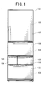
- FIG. 1 is a front view of a refrigerator to which the present invention is applied;
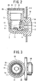
- FIG. 2 is a vertical side view of a chamber lamp device to which any chamber lamp is not attached;
- FIG. 3 is a plan view of the chamber lamp device to which any chamber lamp is not attached; and
- FIG. 4 is a vertical side view of the chamber lamp device to which the chamber lamp is attached.
- An embodiment of the present invention will be described hereinafter with reference to the drawings.
- First,
reference numeral 101 denotes a refrigerator main body constituted of a plurality of food preserving chambers each provided with a front door. This refrigeratormain body 101 is constituted of an insulating material such as urethane foam charged in an outer box and an inner box and between both of the boxes. The inside of this refrigeratormain body 101 is partitioned by partition walls having an insulating function. From an upper part of the main body, there are arranged a refrigeratingchamber 102, avegetable chamber 103, anice compartment 104, atemperature switching chamber 105 which can be set to an environment at a temperature of -18°C to 6°C by user's selection, and afreezing chamber 106. - Moreover, a front-surface opening of the refrigerating
chamber 102 can be closed by an openably closing rotary refrigeratingchamber door 107. Thevegetable chamber 103,ice compartment 104,temperature switching chamber 105, andfreezing chamber 106 arranged under the refrigeratingchamber 102 are closed by a drawer type ofvegetable chamber door 108,ice compartment door 109, temperatureswitching chamber door 110, andfreezing chamber door 111, respectively. Each of the doors are constituted by charging an insulating material such as urethane foam between each door outer box constituted of a steel plate and a door inner box constituted of a hard resin material. - Furthermore, in FIG. 4,
reference numeral 1 denotes a chamber lamp device disposed in the refrigerator, that is, thefreezing chamber 106, therefrigerating chamber 102, and the like. Thischamber lamp device 1 is constituted of achamber lamp 2 and achamber lamp socket 3. Moreover, thechamber lamp 2 is driven by a commercial power voltage to light by means of a control unit (not shown), only when eachdoor - The
chamber lamp socket 3 is constituted of a socketmain body 4, and asupport member 5 attached to an innerbox back wall 112 of themain body 101 to cover the whole socketmain body 4. Moreover, the socketmain body 4 is formed of an insulating member such as a synthetic resin material, and alamp holder 8 to be engaged with amouthpiece 2A of thechamber lamp 2 is disposed on an innerperipheral wall 7 of a chamberlamp attaching portion 10 having a bottomed cylindrical shape. Acenter contact piece 11 is attached to a lower part (bottom part in FIG. 2) of thislamp holder 8. Furthermore, thelamp holder 8 and thecenter contact piece 11 are connected tomale terminals - The
support member 5 is formed of a flexible synthetic resin material such as a deformable flexible polyvinyl chloride resin, and has such a bottomed cylindrical shape as to cover an outer periphery of the socketmain body 4. A tipcylindrical portion 5A of the member extends upwards from the socketmain body 4, and spreads slightly outwardly. A cylindrical attachingbase 5B having aconnector insertion port 14 is disposed in a side part of the main body, and agroove 16 into which the innerbox back wall 112 is fitted is formed in the attaching base. - Moreover, an inner surface of the tip
cylindrical portion 5A of thesupport member 5 is formed to be uneven in such a manner as to repeat recessed portions and protruding portions so that a glass tube 2C of thechamber lamp 2 is easily removed from the support member by manually turning thechamber lamp 2, even in a case where the support member is closely attached to the glass tube for many years, and they stick to each other. - Specifically, as shown in FIG. 3, the inner surface of the tip
cylindrical portion 5A of thesupport member 5 has a sawtoothed shape in whichgentle slopes 17 andsteep slopes 18 both having flat-surface shapes are alternately formed. Thisgentle slope 17 is formed in such a manner that the slope comes close to the center of the tipcylindrical portion 5A toward a direction in which thechamber lamp 2 is attached, that is, a direction of movement in rotating thechamber lamp 2 clockwise. Conversely, the slope is formed to be far from the center of the tipcylindrical portion 5A toward a direction in which thechamber lamp 2 is removed, that is, a direction of movement in rotating thechamber lamp 2 counterclockwise. An annular protrudingportion 20 positioned inside asawtoothed portion 19 and protruded upwards is disposed in an intermediate portion of thesupport member 5 under thesawtoothed portion 19. It is to be noted that the tipcylindrical portion 5A and the annular protrudingportion 20 constitute a collar portion. - As shown in FIG. 4, in a case where the
mouthpiece 2A of thechamber lamp 2 is attached to thechamber lamp socket 3, thesawtoothed portion 19 comes in contact with an intermediate portion of the transparent glass tube 2C of alight emitting portion 2B of thechamber lamp 2, and the protrudingportion 20 is closely attached to a lower part of the glass tube 2C. The gentle slopes 17 and thesteep slopes 18 are arranged in such a manner that an outer peripheral surface of the glass tube 2C contacts thegentle slopes 17 of thesawtoothed portion 19, thereby reducing a sliding resistance, when thechamber lamp 2 is attached. The outer peripheral surface of the glass tube 2C contacts thesteep slopes 18 of thesawtoothed portion 19, thereby increasing the sliding resistance, when the chamber lamp is detached. - When the
chamber lamp 2 is attached to thechamber lamp socket 3 constituted as described above, themouthpiece 2A is fitted into thelamp holder 8 to thereby bring atip terminal 2D of themouthpiece 2A into contact with thecenter contact piece 11, and substantially 1/3 of the transparent glass tube 2C covering thelight emitting portion 2B of thechamber lamp 2 is covered with the tipcylindrical portion 5A of thesupport member 5. In this case, a part (part close to the center of the gentle slope 17) of thegentle slope 17 of thesawtoothed portion 19 on the inner surface of the tipcylindrical portion 5A is brought into contact with the intermediate portion of the glass tube 2C (in this case, the part is not brought into contact with the steep slope 18). Moreover, the protrudingportion 20 is pressed onto the lower art of the glass tube 2C, and brought into surface contact with the glass tube 2C in a closely attached state. - Therefore, a holding force of the
chamber lamp 2 by thechamber lamp socket 3 increases, the holding of thechamber lamp 2 by thechamber lamp socket 3 is assured, and a torque required for loosening thechamber lamp 2 or attaching and tightening the lamp increases. Vibrations due to opening and closing of the refrigeratingchamber door 107 or the like or due to operation of a refrigeration cycle are transferred to vibrate thechamber lamp socket 3 or thechamber lamp 2. Even in this case, thechamber lamp 2 can be prevented from being rotated by the vibrations. - Moreover, even when the
support member 5 is closely attached to the glass tube 2C of thechamber lamp 2 for many years, and they stick to each other, an only part of thegentle slope 17 sticks that is the protruding portion of thesawtoothed portion 19. Therefore, when thechamber lamp 2 is manually turned, the chamber lamp can be easily detached. - Furthermore, when the
chamber lamp 2 rotates in a tightening direction, that is, attaching direction, the glass tube 2C of thechamber lamp 2 abuts on thegentle slope 17 of thesawtoothed portion 19. Since a sliding resistance is small, the rotation of the lamp is permitted. However, when thechamber lamp 2 rotates in a loosening direction, that is, detaching direction, the glass tube 2C of thechamber lamp 2 abuts on thesteep slope 18 of thesawtoothed portion 19, and the sliding resistance increases. Therefore, this rotation can be securely inhibited. Even if there is strong impact or vibration, thechamber lamp 2 can be prevented from being wobbled. - As a result, the
chamber lamp 2 can be securely prevented from being loosened with respect to thechamber lamp socket 3, and it is possible to securely retain contact between themouthpiece 2A and thecenter contact piece 11, that is, contact between the terminal 2D of the tip of themouthpiece 2A and the center contact piece. Therefore, it is possible to securely avoid generation of sparks that might be generated when the contact between themouthpiece 2A and thecenter contact piece 11 becomes uncertain in the refrigerator in which the combustible refrigerant is used. - Furthermore, it is possible to satisfy requirements "when the mouthpiece is inserted into the lamp socket with a torque of 1.0±0.1 Nm, a torque required for turning the mouthpiece by 15° to partially return the mouthpiece, and thereafter removing this mouthpiece is set to 0.3±0.1 Nm or more" defined in, for example, "the Japan Electrical Manufacturer's Association (JEMA), Voluntary Standards, Safety and General Requirements of Hydrocarbon-based Refrigerant Applied Refrigerator".
- Additionally, since the glass tube 2C of the
chamber lamp 2 is closely attached to the annular protrudingportion 20 on the inner surface of the tipcylindrical portion 5A of thesupport member 5, a gas around the chamber lamp can be securely prevented from flowing on the side of themouthpiece 2A. It is possible to more securely avoid the generation of the sparks even in a case where a combustible hydrocarbon-based refrigerant is used in the refrigerator. - It is to be noted that the tip
cylindrical portion 5A of thesupport member 5 is brought into contact with the outer peripheral surface of the glass tube 2C close to thelight emitting portion 2B with a small area via a part (part close to the center of the tipcylindrical portion 5A of the gentle slope 17) of the chamber lamp device of thesawtoothed portion 19. Therefore, little heat is conducted from the glass tube 2C. Even when a flexible resin material is used, the support member is prevented from being thermally deformed, and it is possible to inhibit proceeding of deterioration due to heat with an elapse of years. - The embodiment of the present invention has been described above, various alternatives, modifications, or variations are possible for any person skilled in the art based on the above description, and the present invention include various alternatives, modifications, or variations described above without departing from the scope of the present invention..
Claims (10)
- A refrigerator provided with a chamber lamp socket attached to the inside of a chamber, and a chamber lamp attached to and supported by the chamber lamp socket,
the refrigerator having a collar portion which is provided with unevenness on an inner surface thereof, brought into contact with an outer periphery of a glass tube of the chamber lamp to hold the lamp, and formed of a flexible material. - The refrigerator according to claim 1, wherein the unevenness has a sawtoothed shape constituted by alternately forming gentle slopes and steep slopes to set a resistance in detaching the chamber lamp to be larger than that in attaching the chamber lamp.
- The refrigerator according to claim 1 or 2, wherein an intermediate portion of the collar portion is provided with an annular protruding portion which is closely attached to the outer periphery of the glass tube of the chamber lamp.
- The refrigerator according to any one of claims 1 to 3, wherein a combustible refrigerant is used as a refrigerant.
- The refrigerator according to any one of claims 1 to 4, wherein the chamber lamp is driven by a commercial power supply voltage.
- The refrigerator according to any one of claims 1 to 3, wherein the collar portion is formed of a polyvinyl chloride resin material.
- A chamber lamp socket provided with a collar portion which is brought into contact with an outer periphery of a glass tube of a chamber lamp to hold the lamp and which is formed of a flexible material,
wherein unevenness is formed on an inner surface of the collar portion. - The chamber lamp socket according to claim 7, wherein the unevenness has a sawtoothed shape constituted by alternately forming gentle slopes and steep slopes to set a resistance in detaching the chamber lamp to be larger than that in attaching the chamber lamp.
- The chamber lamp socket according to claim 7 or 8, wherein an intermediate portion of the collar portion is provided with an annular protruding portion to be closely attached to the outer periphery of the glass tube of the chamber lamp.
- The chamber lamp socket according to any one of claims 7 to 9, wherein the collar portion is formed of a polyvinyl chloride resin material.
Applications Claiming Priority (2)
| Application Number | Priority Date | Filing Date | Title |
|---|---|---|---|
| JP2003187075 | 2003-06-30 | ||
| PCT/JP2004/008996 WO2005001354A1 (en) | 2003-06-30 | 2004-06-25 | Interior light socket and refigerator |
Publications (2)
| Publication Number | Publication Date |
|---|---|
| EP1640681A1 true EP1640681A1 (en) | 2006-03-29 |
| EP1640681A4 EP1640681A4 (en) | 2012-04-25 |
Family
ID=33549712
Family Applications (1)
| Application Number | Title | Priority Date | Filing Date |
|---|---|---|---|
| EP04746465A Withdrawn EP1640681A4 (en) | 2003-06-30 | 2004-06-25 | Interior light socket and refigerator |
Country Status (7)
| Country | Link |
|---|---|
| US (1) | US7387398B2 (en) |
| EP (1) | EP1640681A4 (en) |
| JP (1) | JPWO2005001354A1 (en) |
| KR (1) | KR20060029636A (en) |
| CN (1) | CN100575835C (en) |
| TW (1) | TWI321211B (en) |
| WO (1) | WO2005001354A1 (en) |
Families Citing this family (4)
| Publication number | Priority date | Publication date | Assignee | Title |
|---|---|---|---|---|
| DE112005003553T5 (en) * | 2005-07-29 | 2008-03-20 | Nova Elektrick Sanayi Ve Ticaret Anonim Sirketi | Detachable lighting fixture through a special lighting fixture |
| DE102006047235A1 (en) * | 2006-10-04 | 2008-04-10 | Bimed Teknik A.S., Büyükcekmece | Lighting device for e.g. refrigerator, has housing comprising inner side that is covered by covering unit, and electrical conductors guided in area outside of lighting device by recess formed at covering unit and/or housing |
| JP4865051B2 (en) * | 2010-04-20 | 2012-02-01 | シャープ株式会社 | PAR type lighting device |
| US8858013B2 (en) * | 2011-04-29 | 2014-10-14 | Hussmann Corporation | Low heat transfer magnetic shelf attachment |
Family Cites Families (13)
| Publication number | Priority date | Publication date | Assignee | Title |
|---|---|---|---|---|
| US819702A (en) * | 1904-06-11 | 1906-05-01 | Jeremiah Murphy | Locking-socket for electric lights. |
| US3728663A (en) * | 1971-08-03 | 1973-04-17 | Lyall Electric | Flexible lampholder |
| US3915328A (en) * | 1974-02-11 | 1975-10-28 | Tetra Plastics | Frame means for connecting structural members together |
| SE435757B (en) * | 1981-05-12 | 1984-10-15 | Sedaplast Ab | SEALING DEVICE FOR SEALING LAMPS |
| JPH0619180Y2 (en) * | 1987-05-12 | 1994-05-18 | スタンレー電気株式会社 | Socket holder |
| IT1267720B1 (en) * | 1994-05-20 | 1997-02-07 | Zanussi Elettrodomestici | REFRIGERATOR WITH IMPROVED LAMP HOLDER |
| JPH07320531A (en) | 1994-05-23 | 1995-12-08 | Hitachi Ltd | Refrigerator light |
| IT1280798B1 (en) * | 1995-01-24 | 1998-02-11 | Eltek Spa | LIGHTING DEVICE FOR HOUSEHOLD APPLIANCES. |
| JPH08303937A (en) | 1995-04-28 | 1996-11-22 | Matsushita Refrig Co Ltd | Box |
| DE19730357A1 (en) * | 1997-07-15 | 1999-01-21 | Bosch Siemens Hausgeraete | Cooling unit |
| JP3472201B2 (en) | 1998-12-22 | 2003-12-02 | 富士金属株式会社 | Lid with overtightening prevention mechanism. |
| IE20000110A1 (en) * | 2000-02-07 | 2001-08-22 | Loctite R & D Ltd | Applicator, Applicator Cap and a Container Having an Applicator Cap |
| JP2002164138A (en) * | 2000-11-27 | 2002-06-07 | Matsushita Refrig Co Ltd | socket |
-
2004
- 2004-06-15 TW TW093117142A patent/TWI321211B/en not_active IP Right Cessation
- 2004-06-25 WO PCT/JP2004/008996 patent/WO2005001354A1/en not_active Ceased
- 2004-06-25 EP EP04746465A patent/EP1640681A4/en not_active Withdrawn
- 2004-06-25 US US10/562,003 patent/US7387398B2/en not_active Expired - Lifetime
- 2004-06-25 KR KR1020057025206A patent/KR20060029636A/en not_active Ceased
- 2004-06-25 CN CN200480018705A patent/CN100575835C/en not_active Expired - Lifetime
- 2004-06-25 JP JP2005511051A patent/JPWO2005001354A1/en active Pending
Also Published As
| Publication number | Publication date |
|---|---|
| JPWO2005001354A1 (en) | 2006-10-19 |
| TW200502519A (en) | 2005-01-16 |
| CN1816725A (en) | 2006-08-09 |
| WO2005001354A1 (en) | 2005-01-06 |
| TWI321211B (en) | 2010-03-01 |
| CN100575835C (en) | 2009-12-30 |
| KR20060029636A (en) | 2006-04-06 |
| EP1640681A4 (en) | 2012-04-25 |
| US7387398B2 (en) | 2008-06-17 |
| US20060152914A1 (en) | 2006-07-13 |
Similar Documents
| Publication | Publication Date | Title |
|---|---|---|
| US12111086B2 (en) | Mobile cooling box with ice maker | |
| US11821672B2 (en) | Mobile cooling box with air vents | |
| US12247779B2 (en) | Mobile cooling box with user interface module | |
| US12044467B2 (en) | Mobile cooling box with handle module | |
| KR20050069319A (en) | Automatic ice cube-making apparatus for refrigerators | |
| KR20100116147A (en) | Refrigerator Ice Maker | |
| US7387398B2 (en) | Chamber light socket and refrigerator | |
| US20060065006A1 (en) | Refrigerator | |
| US7823408B2 (en) | Icemaker in refrigerator | |
| JP3955700B2 (en) | Refrigerator cabinet and manufacturing method thereof | |
| KR102499060B1 (en) | Portable refrigerator with ice making function | |
| KR20050022690A (en) | A door-switch switching structure for refrigerator | |
| JP4038926B2 (en) | Freezer refrigerator | |
| CN114651150A (en) | Modular LED lighting device | |
| JP3927885B2 (en) | refrigerator | |
| KR101621558B1 (en) | Refrigerator | |
| JP4118644B2 (en) | refrigerator | |
| JP2004020063A (en) | Cooling storage chamber | |
| JP2020190362A (en) | refrigerator | |
| KR20030086738A (en) | Refrigerator with plug socket | |
| KR200187699Y1 (en) | Control panel assembly for refrigerator | |
| KR200183034Y1 (en) | Refrigerator dispenser | |
| JP2004037004A (en) | Refrigerator | |
| JP2004061045A (en) | Storage for cooling | |
| KR20000011222U (en) | Coupling Structure of High Light Lamp |
Legal Events
| Date | Code | Title | Description |
|---|---|---|---|
| PUAI | Public reference made under article 153(3) epc to a published international application that has entered the european phase |
Free format text: ORIGINAL CODE: 0009012 |
|
| 17P | Request for examination filed |
Effective date: 20051219 |
|
| AK | Designated contracting states |
Kind code of ref document: A1 Designated state(s): DE FR GB IT |
|
| DAX | Request for extension of the european patent (deleted) | ||
| RBV | Designated contracting states (corrected) |
Designated state(s): DE FR GB IT |
|
| A4 | Supplementary search report drawn up and despatched |
Effective date: 20120322 |
|
| RIC1 | Information provided on ipc code assigned before grant |
Ipc: F25D 27/00 20060101AFI20120316BHEP |
|
| STAA | Information on the status of an ep patent application or granted ep patent |
Free format text: STATUS: THE APPLICATION IS DEEMED TO BE WITHDRAWN |
|
| 18D | Application deemed to be withdrawn |
Effective date: 20120621 |