EP1640445B1 - Trommel für eine Anlage zur aeroben Fermentierung von Abfällen - Google Patents
Trommel für eine Anlage zur aeroben Fermentierung von Abfällen Download PDFInfo
- Publication number
- EP1640445B1 EP1640445B1 EP20050292003 EP05292003A EP1640445B1 EP 1640445 B1 EP1640445 B1 EP 1640445B1 EP 20050292003 EP20050292003 EP 20050292003 EP 05292003 A EP05292003 A EP 05292003A EP 1640445 B1 EP1640445 B1 EP 1640445B1
- Authority
- EP
- European Patent Office
- Prior art keywords
- drum
- axle
- pinion
- casing
- axis
- Prior art date
- Legal status (The legal status is an assumption and is not a legal conclusion. Google has not performed a legal analysis and makes no representation as to the accuracy of the status listed.)
- Not-in-force
Links
- 239000002699 waste material Substances 0.000 title claims abstract description 46
- 238000010564 aerobic fermentation Methods 0.000 title claims abstract description 10
- 238000009434 installation Methods 0.000 title description 14
- 238000009423 ventilation Methods 0.000 claims abstract description 29
- 238000000855 fermentation Methods 0.000 claims abstract description 10
- 230000004151 fermentation Effects 0.000 claims abstract description 10
- 238000011144 upstream manufacturing Methods 0.000 claims description 21
- 238000006073 displacement reaction Methods 0.000 claims description 8
- 230000002093 peripheral effect Effects 0.000 claims description 5
- 230000000712 assembly Effects 0.000 abstract description 2
- 238000000429 assembly Methods 0.000 abstract description 2
- 241001417494 Sciaenidae Species 0.000 description 6
- 230000005540 biological transmission Effects 0.000 description 3
- 230000000694 effects Effects 0.000 description 3
- 244000005700 microbiome Species 0.000 description 3
- 238000007599 discharging Methods 0.000 description 2
- 230000001174 ascending effect Effects 0.000 description 1
- 238000006243 chemical reaction Methods 0.000 description 1
- 239000003638 chemical reducing agent Substances 0.000 description 1
- 239000000470 constituent Substances 0.000 description 1
- 230000008878 coupling Effects 0.000 description 1
- 238000010168 coupling process Methods 0.000 description 1
- 238000005859 coupling reaction Methods 0.000 description 1
- 230000009977 dual effect Effects 0.000 description 1
- 238000002347 injection Methods 0.000 description 1
- 239000007924 injection Substances 0.000 description 1
- 239000002184 metal Substances 0.000 description 1
- 238000011084 recovery Methods 0.000 description 1
- 238000000926 separation method Methods 0.000 description 1
Images



Classifications
-
- C—CHEMISTRY; METALLURGY
- C12—BIOCHEMISTRY; BEER; SPIRITS; WINE; VINEGAR; MICROBIOLOGY; ENZYMOLOGY; MUTATION OR GENETIC ENGINEERING
- C12M—APPARATUS FOR ENZYMOLOGY OR MICROBIOLOGY; APPARATUS FOR CULTURING MICROORGANISMS FOR PRODUCING BIOMASS, FOR GROWING CELLS OR FOR OBTAINING FERMENTATION OR METABOLIC PRODUCTS, i.e. BIOREACTORS OR FERMENTERS
- C12M23/00—Constructional details, e.g. recesses, hinges
- C12M23/02—Form or structure of the vessel
- C12M23/06—Tubular
-
- C—CHEMISTRY; METALLURGY
- C05—FERTILISERS; MANUFACTURE THEREOF
- C05F—ORGANIC FERTILISERS NOT COVERED BY SUBCLASSES C05B, C05C, e.g. FERTILISERS FROM WASTE OR REFUSE
- C05F17/00—Preparation of fertilisers characterised by biological or biochemical treatment steps, e.g. composting or fermentation
- C05F17/90—Apparatus therefor
- C05F17/921—Devices in which the material is conveyed essentially horizontally between inlet and discharge means
- C05F17/929—Cylinders or drums
-
- C—CHEMISTRY; METALLURGY
- C12—BIOCHEMISTRY; BEER; SPIRITS; WINE; VINEGAR; MICROBIOLOGY; ENZYMOLOGY; MUTATION OR GENETIC ENGINEERING
- C12M—APPARATUS FOR ENZYMOLOGY OR MICROBIOLOGY; APPARATUS FOR CULTURING MICROORGANISMS FOR PRODUCING BIOMASS, FOR GROWING CELLS OR FOR OBTAINING FERMENTATION OR METABOLIC PRODUCTS, i.e. BIOREACTORS OR FERMENTERS
- C12M27/00—Means for mixing, agitating or circulating fluids in the vessel
- C12M27/10—Rotating vessel
-
- Y—GENERAL TAGGING OF NEW TECHNOLOGICAL DEVELOPMENTS; GENERAL TAGGING OF CROSS-SECTIONAL TECHNOLOGIES SPANNING OVER SEVERAL SECTIONS OF THE IPC; TECHNICAL SUBJECTS COVERED BY FORMER USPC CROSS-REFERENCE ART COLLECTIONS [XRACs] AND DIGESTS
- Y02—TECHNOLOGIES OR APPLICATIONS FOR MITIGATION OR ADAPTATION AGAINST CLIMATE CHANGE
- Y02P—CLIMATE CHANGE MITIGATION TECHNOLOGIES IN THE PRODUCTION OR PROCESSING OF GOODS
- Y02P20/00—Technologies relating to chemical industry
- Y02P20/141—Feedstock
- Y02P20/145—Feedstock the feedstock being materials of biological origin
-
- Y—GENERAL TAGGING OF NEW TECHNOLOGICAL DEVELOPMENTS; GENERAL TAGGING OF CROSS-SECTIONAL TECHNOLOGIES SPANNING OVER SEVERAL SECTIONS OF THE IPC; TECHNICAL SUBJECTS COVERED BY FORMER USPC CROSS-REFERENCE ART COLLECTIONS [XRACs] AND DIGESTS
- Y02—TECHNOLOGIES OR APPLICATIONS FOR MITIGATION OR ADAPTATION AGAINST CLIMATE CHANGE
- Y02W—CLIMATE CHANGE MITIGATION TECHNOLOGIES RELATED TO WASTEWATER TREATMENT OR WASTE MANAGEMENT
- Y02W30/00—Technologies for solid waste management
- Y02W30/40—Bio-organic fraction processing; Production of fertilisers from the organic fraction of waste or refuse
Definitions
- the invention relates to a drum for the aerobic fermentation of waste, and to an installation comprising such a drum.
- Such drums generally comprise a cylindrical casing, driven in rotation about its axis, in which the wastes ferment under the action of aerobic microorganisms, a ventilation device being provided for this purpose to create a circulation of air to the air. inside the drum. It is in particular known to connect a fan to the upstream end of the casing, openings being provided at the downstream part of the casing to allow the circulation of air inside the drum, by suction or discharge induced by the fan.
- the document FR 2,746,410 discloses a drum comprising a transverse wall forming an exit shield, in which an opening is formed.
- This opening has a dual function: on the one hand, it allows the unloading of fermented waste in the unloading phase and, on the other hand, it allows the passage of ventilation air in the unloading phase.
- This structure has a number of limitations. Firstly, it requires the use of means of coupling / uncoupling of the output shield and the envelope, depending on whether one is in the unloading phase or not. Moreover, the fact that the same opening serves both the unloading of waste and ventilation does not allow to obtain an optimal air flow in the drum. The performance of the drum in terms of the fermentation capacity of the waste is therefore not fully satisfactory.
- the document FR 2 832 780 describes a drum whose cylindrical envelope is provided with vents that can be opened or closed by a device comprising a movable plate.
- vents that can be opened or closed by a device comprising a movable plate.
- such an arrangement of the vents poses different problems.
- the air is introduced by the vents inside the casing radially.
- This air injection mode does not allow optimal distribution and air circulation in the drum.
- the quality of ventilation at the inside of the envelope is crucial, because it conditions the activity of the microorganisms ensuring the fermentation, and thus the efficiency of the drum.
- the document FR 2 796 865 discloses a drum for fermentation comprising a casing for receiving waste and being rotatable about its longitudinal axis.
- the drum also comprises a fixed transversal wall for the arrival of the waste to be treated situated at the entrance to the drum and stationary with respect to the rotary envelope and a transverse outlet wall of treated waste situated at the outlet of the drum and rotating simultaneously with the rotating envelope.
- the transverse outlet wall includes a waste evacuation door and a ventilation opening separate from the hatch. A grid is disposed against the ventilation opening.
- the object of the invention is to solve these problems.
- the transverse wall comprises at least one ventilation orifice distinct from the hatch, said orifice being arranged so as to allow axial circulation of air through it, between the inside and the outside of the envelope.
- the drum comprises a device for closing off the ventilation orifice, said device being arranged to be able to be moved between a closed position, in which the ventilation orifice is closed, and an open position, in which the Ventilation hole is clear.
- the closure device is held in its closed position by return means, said closure device being able to be moved to its open position under the action of a bearing force exerted to against the force of the return means.
- the closure device may comprise at least one shutter arranged so as to be able to close, respectively to disengage the orifice, when the shutter device is in the closed position, respectively of opening, and at least one rod integral with the shutter, the shutter-rod assembly being mounted on the outer face of the transverse wall so as to be able to slide substantially radially.
- the invention relates to an installation for the aerobic fermentation of waste, comprising a drum as previously described, drum support means arranged so that the nominal axis of the drum envelope is substantially horizontal or slightly inclined relative to the horizontal, and at least one drive system adapted to allow the drum drive in rotation about its axis.
- the installation comprises for example a ramp in a fixed arc relative to the ground, disposed outside the envelope, substantially concentrically with the envelope, said ramp being adapted to cooperate with a roller provided on the device shutter, so as to cause the displacement of the shutter device from the closed position to the open position by pressing the roller against the ramp.
- the ramp is arranged to cooperate with the roller when the ventilation orifice is not disposed opposite the waste present in the drum.
- the ramp is for example disposed above the drum, and extends at least over a quarter of the periphery of the drum, between a vertical plane passing through the drum axis and a horizontal plane passing through the drum. drum axis.
- the ramp may comprise a substantially circular central zone, and an inlet zone and an outlet zone capable of guiding the displacement of the closure device between its open and closed positions.
- the installation comprises a ventilation device allowing the circulation of air inside the drum, the ventilation device comprising at least one fan connected to the upstream end of the casing of the drum, said fan being arranged to suck and / or discharge the air, so that the air is introduced, respectively evacuated, at the end downstream of the casing substantially axially through the ventilation opening.
- the drive system comprises a pinion rotated about a main axis substantially parallel to the nominal axis of the drum and a toothed ring integral with the drum, said pinion being arranged to engage the ring to control the rotation of the drum about its nominal axis, the pinion being further mounted movable relative to a first axis of floating distinct from the main axis of the pinion, said assembly being arranged to allow at least the free rotation of the pinion around said first floating axis.
- the pinion may also be mounted movable relative to a second floating axis distinct from the main axis of the pinion and the first floating axis, said assembly being arranged to allow at least the free rotation of the pinion about said second axis of floating. .
- FIG. 1 represents a facility 1 for the aerobic fermentation of waste.
- the installation 1 comprises first of all a drum 2, itself comprising a substantially cylindrical envelope 3, of nominal axis 4, as well as an input shield comprising an upstream transverse wall 5, and an exit shield comprising a downstream transverse wall 6, the transverse walls being substantially disc-shaped.
- the envelope 3 is made of metal. It can reach 40 to 50 m in length, and its diameter can be of the order of 3 to 5 m.
- the X axis is defined as the axis parallel to the nominal axis 4, oriented downstream, the Z axis as the vertical ascending axis, and the Y axis such that (X, Y, Z) form an orthogonal reference.
- the drum 2 is disposed on the ground so that its axis 4 is substantially horizontal, or slightly inclined with respect to the horizontal, of the upstream transverse wall 5 towards the downstream transverse wall 6, by an angle of less than 10 °, even less than 5 °.
- the installation 1 further comprises a drive system 7 in rotation of the drum 2 about the axis 4, disposed about two thirds of the casing 3 from the upstream transverse wall 5.
- the direction of rotation is indicated in the figures by the arrows R.
- Two rotation guiding devices, respectively upstream 8 and downstream 9 are also provided.
- the installation 1 comprises means for loading the waste to be treated, connected to the upstream end of the casing 3 of the drum 2.
- These means comprise a loading hopper 10, as well as a conduit 11 for feeding the waste from the hopper 10 to the inside of the drum 2, via an orifice formed in the upstream transverse wall 5.
- a fan 12 connected to the opening of the upstream transverse wall 5 through which the waste is introduced, the fan 12 being able to cause an air flow inside the drum 2, as we will see later.
- a determined mass of waste is introduced at selected moments in the drum 2, via the upstream transverse wall 5. During this loading phase, the fan 12 is not in operation.
- Knives may be provided inside the casing 3 to promote brewing and separation of waste.
- the waste is gradually fermented by aerobic micro-organisms whose activity is increased by a suitable air circulation.
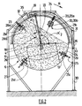
- the waste present in the drum 2 occupy for example two thirds of the volume of the drum. Due to the rotation of the drum 2, the waste forms on average a free surface 22 inclined relative to the horizontal (see figure 2 ). In the embodiment shown, the free surface 22 is inclined at an angle close to 45 °. Of course, this angle depends in particular on the nature of the waste and the speed of rotation of the drum 2.
- the downstream transverse wall 6 comprises a hatch 13 for evacuation of the waste thus fermented.
- this waste is in the form of relatively large clusters.
- a cylindrical piece 14 integral with the drum 2 is provided. This piece 14, open at its upstream and downstream ends, has a cylindrical lateral surface provided with orifices, so as to form a screen.
- the installation 1 comprises means for discharging the fermented waste, located downstream of the drum 2.
- These means comprise for example a recovery hopper 15 and a belt conveyor 16 adapted to convey the waste to another unit.
- the hatch 13 for discharging fermented waste is located in the peripheral zone of the transverse wall 6 of the exit shield.
- the hatch 13 has substantially the shape of a rectangle whose one side is rounded so as to conform locally to the circular shape of the edge of the transverse wall 6.
- the height of the hatch 13, on its side rounded to its opposite side, is of the order of a half radius of the transverse wall 6, and the distance between the two other sides of the hatch 13 is close to twice the height.
- a shutter panel 17 of the hatch 13 is provided, so that one can choose to unload waste or not. For example, it can be expected to keep the hatch 13 closed during the night, and open it during the day.
- the panel 17 is mounted movably between a closed position, in which it closes the hatch 13, and an open position, in which the hatch 13 is disengaged.
- the device 18 may consist of a cylinder, a threaded sleeve assembly - threaded screw, or any other suitable mechanism.
- the transverse wall 6 also comprises a plurality of ventilation holes 20 intended to allow the entry of air into the drum 2, and the circulation of this air substantially parallel to the axis 4, thanks to the suction caused by the fan 12.
- the transverse wall 6 has at least two sets of at least one ventilation orifice, said assemblies being distributed over the surface of said transverse wall and spaced apart from each other substantially regularly. At least one assembly comprises at least two orifices located substantially on the same radius, in the peripheral zone of the transverse wall.
- the orifices 20 are distributed on the surface of the transverse wall 6 in four sets 21 of two orifices 20 each, respectively a first assembly 21a, a second assembly 21b, a third assembly 21c and a fourth assembly 21d.
- the orifices 20 are located substantially on the same radius of the transverse wall 6, in the peripheral zone of said wall 6.
- a first orifice 20a said outside, is for example located at a distance from the circular edge of the transverse wall 6 of the order of 10 to 20 cm, a second hole 20b, said inner being at a distance from the circular edge of the transverse wall 6 of the order of 30 to 40 cm.
- the outer orifices 20a of the four sets 21 are located substantially on the same circle centered on the axis 4.
- the inner orifices 20b of the four sets 21 are located substantially on the same circle, of smaller diameter, centered on the axis 4.
- the third and fourth sets 21c, 21d are located on either side of the hatch 13, and angularly spaced about 100 °.
- the angular gap between the first and fourth sets 21a, 21d on the one hand, and between the second and third sets 21b, 21c on the other hand, is about 95 °.
- the orifices 20 have substantially the same shape. They are rectangular, of height (according to a radius) of the order of 5 to 15 cm, and width of the order of 25 to 40 cm. The two orifices 20a, 20b of the same set are spaced radially by a distance of the order of 10 cm.
- a closure device 23 is provided, for each assembly 21, to allow controlled opening and closing of the orifices 20.
- Each closure device 23 firstly comprises a rod 24 disposed outside the drum 2, opposite, substantially parallel and in close proximity to the transverse wall 6, said rod 24 extend substantially radially.
- the rod 24 is guided in radial translation by sliding sleeves 26, 27 located respectively at the inner end portion and the outer end portion of the rod 24.
- the rod 24 carries two flaps 28a, 28b disposed substantially parallel to the transverse wall 6, and in the immediate vicinity thereof.
- the position of the flaps on the rod 24, their shape and their dimensions are provided to allow on the one hand the closing of the orifices 20, and on the other hand the disengagement of these orifices 20.
- the flaps 28a, 28b have a rectangular shape substantially identical to the shape of the orifices 20, but of slightly larger dimensions, so as to cover the orifices 20 to ensure their closure.
- the spacing between the two flaps 28a, 28b is adapted to the spacing between the two orifices 20a, 20b of the same assembly 21.
- the installation 1 further comprises a frame 30, part of which extends above the drum 2 and supports a ramp 31.
- the ramp 31 has the shape of a circular arc, placed outside the casing 3, substantially concentric.
- the ramp 31 is arranged so as to extend facing the free surface 22 at least from one longitudinal end to the other of this free surface 22.
- the ramp 31 extends about 130 °, between a first end 32 located upstream of the vertical, at an angle ⁇ 1 of about 20 °, and a second end 33 located downstream of the vertical, at an angle ⁇ 2 of about 110 °, relative to the direction of rotation R of the drum 2.
- the free surface 22 substantially forms a rope of the ramp 31.
- the ramp 31 comprises a central zone 34, the face facing the drum 2 is substantially circular, and an inlet zone 35 and an outlet zone 36 whose faces facing the drum 2 are inclined so that the ends 32, 33 of the ramp 31 are located at a radial distance from the drum 2 greater than the central zone 34.
- the roller 25 of a closure device 23 comes into contact with the inlet zone 35 of the ramp 31 and moves towards the central zone 34, thereby causing the sliding of the rod 24 radially, towards the axis 4 of the drum 2, by compressing the spring 29.
- the radial distance between the ramp 31 and the drum 2 is provided to allow the roller 25 to cooperate with the ramp 31, as well as a displacement of determined amplitude of the rod 24 so that the flaps 28a, 28b move towards the axis 4, thus releasing the orifices 20a, 20b.
- the displacement of the rod 24 is such that, in particular, the outer flap 28a is then between the outer and inner openings 20a 20b, so that said flap has cleared the outer orifice 20a without closing the inner orifice 20b.
- the orifices 20 are disengaged when they are not facing the waste present in the drum 2, thus permitting the entry of air axially by the action of the fan 12, and the orifices 20 are closed off when they are in waste, so as to prevent inadvertent unloading of the drum 2.
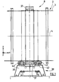
- the upstream device 8 for guiding rotation of the drum 2 is now described with reference to the figures 3 and 4 . It should be noted that the downstream rotating guide device 9 may be identical or not.
- the upstream device 8 for guiding rotation firstly comprises a holding member, such as a belt 37, secured to the casing 3 of the drum 2.
- a support device 38 of the drum 2 is fixed to the ground.
- the support device 38 comprises a frame 39 which is associated with four rollers 40 of axis 41 parallel to the axis 4, arranged substantially at the corners of a rectangle.
- the drum rests on the rollers 40 which allow its rotation about the axis 4.
- On the upper face of the frame 39 are fixed projecting members 42 associated with a piece 43 secured to the belt 37 via bearings 44, so as to allow , locally, a certain amplitude of rotation of the drum 2 relative to the frame 39 around the axis Y.
- the drive system 7 comprises a drive member such as a ring gear 45 integral with the drum 2, whose nominal axis substantially coincides with the axis 4.
- the ring gear 45 is able to cooperate with a motor device for the drive. rotation of the drum 2.
- the motor device comprises a motor 46 of axis substantially parallel to the axis 4, the rotation of which is transmitted via a belt 48 to a first device reducer.
- the belt 48 is located in a plane substantially orthogonal to the axis 4, the first reducing device being further away from the drum 2 than the motor 46.
- the motor 46 and the first reducing device are mounted on a support fixed to the ground.
- the output of the first reducing device is connected to the input of a second reducing device via a connecting device.
- the connecting device comprises for example a transmission rod substantially parallel to the axis 4, whose upstream end is associated with the output of the first reduction device by a first gimbal, and whose downstream end is associated with the input the second reduction device by a second gimbal and sliding means along the axis X.
- the sliding means are formed by a first cylinder of axis X capable of sliding along its axis in a second concentric cylinder, the assembly being protected by a flexible diaphragm bellows.
- the second reduction device comprises a toothed sleeve integral with the second cylinder, arranged to engage a pinion 58 of main axis 59 substantially parallel to the nominal axis 4 of the drum 2.
- the pinion 58 is thus rotated around its axis. main axis 59, by the motor 46.
- the pinion 58 is located between the drum 2 and the second reducing device, and is arranged to engage the ring 45 to control the rotation of the drum 2 about its nominal axis 4.
- the pinion 58 is partly housed in a housing 60 which are associated in rotation two rollers 61 of axis 62 substantially parallel to the axis X.
- the rollers 61 are arranged to maintain the ring gear 45 in engagement with the pinion 58. For this purpose, they are arranged at the upstream ends and downstream of the ring 45, against a face 63 of said ring 45 directed towards the axis 4.
- the casing 60 is fixed to the ground by means of a substantially vertical bar 64 whose lower end is rotatably associated with the ground around a first floating axis 65, substantially parallel to the axis X, and of which the upper end is associated with the housing 60 rotatably about a second floating axis 66 substantially parallel to the Y axis.
- the second floating axis 66 is located substantially in a plane (Y, Z) median of the ring 45.
- the length of the bar 64 is chosen, depending on the support of the motor 46 and the first reducing device, so that the bar transmission is substantially horizontal.
- the pinion 58 When the drum expands, due to the increase in temperature caused by the fermentation of the waste, the pinion 58 is able to "follow" the deformation of the drum 2, at the ring gear 45, thanks to the floating axes 65 , 66, so that the teeth of the pinion 58 and the ring 45 always remain in engagement.
- This displacement of the pinion 58 is “free”, that is to say caused by the displacement of the ring 45, as opposed to the rotation of the pinion 58 about its main axis 59, which is motorized.
- the pinion 58 is rotatably mounted about the floating axes 65, 66.
- the pinion 58 could be mounted on elastomeric pads capable of allowing such rotation.
- the figure 7 schematically illustrates the radial deformation of the drum 2, leading to the increase of the diameter of the ring 45. Consequently, the pinion 58, held against the ring 45 by the roller 61, moves in rotation about the axis 65 , from an angle ⁇ . Thus, despite the radial expansion of the drum 2, the pinion 58 remains in engagement with the ring 45.
- the drum 2 is also likely to expand axially.
- the drum 2 being held at its end portions by the rotation guiding devices 8, 9, the axial elongation of the drum 2 leads to a deformation of the deflection type, the axis 4 then being no longer parallel to the X axis , especially in the area of the drive system 7.
- the universal joints make it possible to ensure the transmission of the motor 46 to the pinion 58 even when the axes of the motor and the pinion are not perfectly aligned because of the expansion of the drum 2.
- the connecting device comprising the gimbals as well as the sliding means is arranged to allow the rotation of the pinion 58 around the first and / or second floating axis 65,66.
- the drive system is therefore able to compensate for misalignment of the axes 4, 59 during installation, or following the expansion of the drum.
- the amplitude of the rotational movement of the pinion 58 around the first and / or second floating axis 65, 66 is less than 10 ° on either side of the rest position.
- the drive system may be devoid of the first and second axes of floating, the only degree of freedom of the pinion 58 is then its rotational movement about its main axis.
- This drive system less robust, may nevertheless be suitable in the case where the expansion of the drum is not too important.
Landscapes
- Chemical & Material Sciences (AREA)
- Health & Medical Sciences (AREA)
- Life Sciences & Earth Sciences (AREA)
- Engineering & Computer Science (AREA)
- Organic Chemistry (AREA)
- Bioinformatics & Cheminformatics (AREA)
- Zoology (AREA)
- Wood Science & Technology (AREA)
- Biochemistry (AREA)
- Biotechnology (AREA)
- Microbiology (AREA)
- General Health & Medical Sciences (AREA)
- Biomedical Technology (AREA)
- Sustainable Development (AREA)
- General Engineering & Computer Science (AREA)
- Genetics & Genomics (AREA)
- Clinical Laboratory Science (AREA)
- Molecular Biology (AREA)
- General Chemical & Material Sciences (AREA)
- Chemical Kinetics & Catalysis (AREA)
- Fertilizers (AREA)
- Treatment Of Sludge (AREA)
- Apparatus Associated With Microorganisms And Enzymes (AREA)
- Processing Of Solid Wastes (AREA)
Claims (15)
- Trommel für eine Anlage (1) für die aerobe Fermentierung von Abfällen, die folgende Teile umfaßt:- einen Schacht (3), in den die zu verarbeitenden Abfälle eingeleitet werden sollen, wobei der besagte Schacht (3) ein oberstromiges Ende, ein unterstromiges Ende und eine Nennachse (4) umfaßt, wobei der besagte Schacht (3) dazu bestimmt ist, bei der Fermentierung in Drehung um seine Achse (4) versetzt zu werden;- einen Ausgangsschild mit einer Querwand (6), die gegenüber dem unterstromigen Ende des Schilds (3) angeordnet ist;- eine Klappe (13), die in der Querwand (6) vorgesehen und geeignet ist, die Ausleitung der fermentierten Abfälle zu ermöglichen;in der die Querwand (6) zumindest eine Belüftungsöffnung (20, 20a, 20b) außer der Klappe (13) umfaßt, wobei die besagte Öffnung so angeordnet ist, daß sie eine axiale Luftzirkulation durch sie hindurch zuläßt, und zwar zwischen dem Inneren und dem Äußeren des Schachts;
dadurch gekennzeichnet, daß sie eine Vorrichtung für den Verschluß (23) der Belüftungsöffnung (20, 20a, 20b) umfaßt, wobei die besagte Vorrichtung so gestaltet ist, daß sie bewegt werden kann zwischen einer Verschlußposition, in der die Belüftungsöffnung verschlossen ist, und einer Öffnungsposition, in der die Belüftungsöffnung frei ist. - Trommel nach Anspruch 1, dadurch gekennzeichnet, daß die Verschlußvorrichtung (23) durch Rückhaltemittel (29) in ihrer Verschlußposition gehalten wird, wobei die besagte Verschlußvorrichtung unter Wirkung einer Auflagekraft entgegen der Kraft der Rückhaltemittel in ihre Öffnungsposition versetzt werden kann.
- Trommel nach Anspruch 1 oder 2, dadurch gekennzeichnet, daß die Verschlußvorrichtung (23) zumindest eine Klappe (28a, 28b) umfaßt, die so angeordnet ist, daß die Öffnung (20, 20a, 20b) verschlossen beziehungsweise freigegeben werden kann, wenn die Verschlußvorrichtung in Verschlußposition beziehungsweise Öffnungsposition ist, und zumindest eine Stange (24), die fest mit der Klappe (28a, 28b) verbunden ist, wobei das Ensemble aus Klappe und Stange auf die Außenseite der Querwand (6) so montiert ist, daß es frei radial gleiten kann.
- Trommel nach einem beliebigen der vorstehenden Ansprüche 1 bis 3, dadurch gekennzeichnet, daß die Querwand (6) zumindest zwei Ensembles (21, 21a, 21b, 21c, 21d) mit mindestens einer Belüftungsöffnung (20, 20a, 20b) aufweist, wobei die besagten Ensembles auf der Oberfläche der besagten Querwand (6) verteilt und voneinander deutlich gleichmäßig getrennt sind.
- Trommel nach Anspruch 4, dadurch gekennzeichnet, daß zumindest ein Ensemble (21) zumindest zwei Öffnungen (20a, 20b) umfaßt, die sich deutlich auf einem gleichen Radius in einer peripheren Zone der Querwand (6) befinden.
- Trommel nach einem beliebigen der vorstehenden Ansprüche 1 bis 5, dadurch gekennzeichnet, daß sich die Klappe (13) in der peripheren Zone der Querwand (6) befindet.
- Trommel nach einem beliebigen der vorstehenden Ansprüche 1 bis 6, dadurch gekennzeichnet, daß sie eine Verschlußplatte (17) der Klappe (13) umfaßt, die mobil zwischen einer Verschlußposition, in der sie die Klappe verschließt, und einer Öffnungsposition montiert ist, in der die Klappe frei ist.
- Anlage für die aerobe Fermentierung von Abfällen, dadurch gekennzeichnet, daß sie folgende Teile umfaßt:- eine Trommel (2) nach einem beliebigen der vorstehenden Ansprüche;- Stützmittel (38) der Trommel, die so gestaltet sind, daß die Nennachse (4) des Schachts (3) der Trommel deutlich horizontal oder gegenüber der Horizontalen leicht geneigt ist;- und zumindest ein Antriebssystem (7), das geeignet ist, den Antrieb der Trommel (2) in Drehung um ihre Achse (4) zu ermöglichen.
- Anlage nach Anspruch 8, dadurch gekennzeichnet, daß sie eine Rampe (31) wie ein fixer Kreisbogen im Verhältnis zum Boden umfaßt, die außerhalb des Schachts (3) deutlich konzentrisch zum Schacht angeordnet ist, wobei die besagte Rampe (31) geeignet ist, mit einer auf der Verschlußvorrichtung (23) vorgesehenen Rolle (25) zusammenzuwirken, so daß sie die Verschiebung der Verschlußvorrichtung von der Verschlußposition zur Öffnungsposition durch Drücken der Rolle gegen die Rampe auslöst.
- Anlage nach Anspruch 9, dadurch gekennzeichnet, daß die Rampe (31) gestaltet ist, um mit der Rolle (25) zusammenzuwirken, wenn die Belüftungsöffnung (20) nicht gegenüber den in der Trommel (2) vorhandenen Abfällen angeordnet ist.
- Anlage nach Anspruch 9 oder 10, dadurch gekennzeichnet, daß die Rampe (31) einen zentralen deutlich kreisförmigen Bereich (34) umfaßt sowie einen Eingangsbereich (35) und einen Ausgangsbereich (36), die geeignet sind, die Verschiebung der Verschlußvorrichtung (23) zwischen ihrer Öffnungsposition und ihrer Verschlußposition zu führen.
- Anlage nach einem beliebigen der vorstehenden Ansprüche 9 bis 11, dadurch gekennzeichnet, daß die Rampe (31) über der Trommel (2) abgeordnet ist und sich zumindest über ein Viertel der Peripherie der Trommel (2) zwischen einer vertikalen Ebene, die durch die Achse der Trommel geht, und einer horizontalen Ebene, die durch die Achse der Trommel verläuft, erstreckt.
- Anlage nach einem beliebigen der vorstehenden Ansprüche 8 bis 12, dadurch gekennzeichnet, daß sie eine Belüftungsvorrichtung umfaßt, die die Luftzirkulation im Innern der Trommel (2) ermöglicht, wobei die Belüftungsvorrichtung zumindest einen Ventilator (12) umfaßt, der mit dem oberstromigen Ende des Schachts (3) der Trommel verbunden ist, wobei der besagte Ventilator (12) gestaltet ist, um die Luft anzusaugen und/oder zurückzudrängen, so daß die Luft eingeführt beziehungsweise am unterstromigen Ende des Schachts (3) deutlich axial durch die Belüftungsöffnung (20) herausgeführt wird.
- Anlage nach einem beliebigen der vorstehenden Ansprüche 8 bis 13, dadurch gekennzeichnet, daß das Antriebssystem ein Ritzel (58) umfaßt, das in Drehung um eine Hauptachse (59) versetzt wird, die deutlich parallel zur Nennachse (4) der Trommel (2) verläuft, und einen Zahnkranz (45), der fest mit der Trommel (2) verbunden ist, wobei das besagte Ritzel (58) so angeordnet ist, daß es in den Kranz (45) eingreift, um die Drehung der Trommel (2) um ihre Nennachse (4) zu steuern, wobei das Ritzel (58) ferner im Verhältnis zu einer ersten Schwebeachse (65) mobil montiert ist, die von der Hauptachse (59) des Ritzels (58) getrennt ist, wobei die besagte Montage so gestaltet ist, daß sie zumindest das freie Drehen des Ritzels um die besagte erste Schwebeachse zuläßt.
- Anlage nach Anspruch 14, dadurch gekennzeichnet, daß das Ritzel (58) ferner im Verhältnis zu einer zweiten Schwebeachse (66) mobil montiert ist, die von der Hauptachse (59) des Ritzels (58) und der ersten Schwebeachse (65) getrennt ist, wobei die besagte Montage so gestaltet ist, daß sie zumindest das freie Drehen des Ritzels um die besagte zweite Schwebeachse zuläßt.
Priority Applications (1)
| Application Number | Priority Date | Filing Date | Title |
|---|---|---|---|
| PL05292003T PL1640445T3 (pl) | 2004-09-27 | 2005-09-27 | Bęben przeznaczony do instalacji do fermentacji aerobowej odpadów |
Applications Claiming Priority (1)
| Application Number | Priority Date | Filing Date | Title |
|---|---|---|---|
| FR0452164A FR2875812B1 (fr) | 2004-09-27 | 2004-09-27 | Tambour destine a une installation pour la fermentation aerobie de dechets |
Publications (2)
| Publication Number | Publication Date |
|---|---|
| EP1640445A1 EP1640445A1 (de) | 2006-03-29 |
| EP1640445B1 true EP1640445B1 (de) | 2011-02-02 |
Family
ID=34949275
Family Applications (1)
| Application Number | Title | Priority Date | Filing Date |
|---|---|---|---|
| EP20050292003 Not-in-force EP1640445B1 (de) | 2004-09-27 | 2005-09-27 | Trommel für eine Anlage zur aeroben Fermentierung von Abfällen |
Country Status (5)
| Country | Link |
|---|---|
| EP (1) | EP1640445B1 (de) |
| AT (1) | ATE497531T1 (de) |
| DE (1) | DE602005026197D1 (de) |
| FR (1) | FR2875812B1 (de) |
| PL (1) | PL1640445T3 (de) |
Families Citing this family (7)
| Publication number | Priority date | Publication date | Assignee | Title |
|---|---|---|---|---|
| FR2956990B1 (fr) | 2010-03-08 | 2012-04-20 | Vinci Environnement | Procede et dispositif de traitement des produits lourds issus d'un affinage de dechets provenant d'un traitement biologique. |
| CN102701556B (zh) * | 2012-05-22 | 2013-11-27 | 陕西沃升机械制造有限公司 | 滚筒式高效污泥无害化处理设备 |
| FR3014868B1 (fr) * | 2013-12-12 | 2017-12-08 | Veolia Proprete | Tambour de pre-compostage |
| CN106892686B (zh) * | 2017-04-24 | 2022-06-21 | 河南正达环保科技有限公司 | 一种滚筒式有机物发酵装置及其发酵筒 |
| CN108441321B (zh) * | 2018-05-23 | 2023-10-27 | 郑州英莱机电设备有限公司 | 一种用于病死动物尸体炼油和发酵的设备 |
| CN110079440A (zh) * | 2019-04-10 | 2019-08-02 | 广西大自然再生资源有限公司 | 生物滚筒发酵罐装置 |
| CN113812261B (zh) * | 2021-03-17 | 2023-05-09 | 陕西顶端果业科技有限公司 | 一种苹果亚科类果实自动采摘机 |
Family Cites Families (3)
| Publication number | Priority date | Publication date | Assignee | Title |
|---|---|---|---|---|
| FR2746410B1 (fr) * | 1996-03-22 | 1998-04-24 | Sogea | Systeme de fermentation aerobie de dechets organiques |
| FR2796865B1 (fr) * | 1999-07-28 | 2003-06-13 | Sge Environnement | Tambour destine a un appareil de traitement de dechets et appareil correspondant |
| FR2832780B1 (fr) * | 2001-11-23 | 2004-11-12 | Bruaysienne | Dispositif pour l'ouverture et la fermeture controlee d'un event de tambour tournant et tambour tournant comprenant au moins un dispositif de ce type |
-
2004
- 2004-09-27 FR FR0452164A patent/FR2875812B1/fr not_active Expired - Fee Related
-
2005
- 2005-09-27 DE DE200560026197 patent/DE602005026197D1/de active Active
- 2005-09-27 PL PL05292003T patent/PL1640445T3/pl unknown
- 2005-09-27 AT AT05292003T patent/ATE497531T1/de not_active IP Right Cessation
- 2005-09-27 EP EP20050292003 patent/EP1640445B1/de not_active Not-in-force
Also Published As
| Publication number | Publication date |
|---|---|
| EP1640445A1 (de) | 2006-03-29 |
| PL1640445T3 (pl) | 2012-01-31 |
| FR2875812B1 (fr) | 2007-02-02 |
| DE602005026197D1 (de) | 2011-03-17 |
| FR2875812A1 (fr) | 2006-03-31 |
| ATE497531T1 (de) | 2011-02-15 |
Similar Documents
| Publication | Publication Date | Title |
|---|---|---|
| EP2232075B1 (de) | Erweiterte peristaltische pumpe | |
| EP0062769B1 (de) | Verfahren zur Betätigung einer oszillierenden Verteilerschurre in einem unter Druck stehenden Behälter, Vorrichtung zur Durchführung dieses Verfahrens und mit dieser Vorrichtung versehene Schachtofenbeschickungsanlage | |
| EP0143057B1 (de) | Entladevorrichtung insbesondere für Behälter mit rundem Boden | |
| CH650060A5 (fr) | Dispositif auxiliaire de commande, pour portes ou grilles enroulables ou portes sectionnelles | |
| EP1640445A1 (de) | Trommel für eine Anlage zur aeroben Fermentierung von Abfällen | |
| EP1129220A1 (de) | Verteilerschurre für schüttgut | |
| FR2482276A1 (fr) | Dispositif de transport equipant un four a passage continu | |
| EP1640446B1 (de) | Anlage zur aeroben Fermentierung von Abfällen | |
| EP0730666B1 (de) | Vorrichtung zur beschickung eines schachtofen | |
| EP1019312B1 (de) | Linearschlitten mit entkuppelbarer mutter für hebevorrichtungen mit spindelantrieb | |
| FR2665648A1 (fr) | Machine a broyer amelioree. | |
| EP1516836B1 (de) | Vorrichtung zum Entleeren von einem einen flachen Boden aufweisendem Silo | |
| EP1544141B1 (de) | Stopvorrichtung für eine Bogenzuführvorrichtung | |
| FR2706818A1 (de) | ||
| EP4420803B1 (de) | Walzwerk mit beweglichem käfig und abgedichteter tür | |
| EP4029812B1 (de) | Materialfördervorrichtung mit abnehmbarer antriebswelle | |
| EP0560662A1 (de) | Verfahren und Anlage zum Walzen einer Metallplatte | |
| FR2507118A1 (fr) | Appareil de distribution orientee de petites pieces en vue de leur assemblage ou montage ulterieurs | |
| FR2872446A1 (fr) | Dispositif de transfert etanche a double porte comportant des organes d'actionnement des portes equipes de hublots | |
| FR2571161A1 (fr) | Mecanisme de mise en procession et d'ejection automatiques d'un element cylindrique tournant. | |
| EP0955255B1 (de) | Schneckenaustragsvorrichtung mit verbessertem Drehantrieb | |
| FR3009303A1 (fr) | Biostabiliseur comprenant une enceinte cylindre constituee par l'association de deux tubes dans le prolongement l'un de l'autre | |
| EP0410916B1 (de) | Längsabzugeinrichtung für langgestreckte oder aneinandergereihte Bunker, insbesondere für Kokereibunker | |
| FR3145394A1 (fr) | Ensemble de vannes a dispositif d’actionnement motorise commun | |
| WO1997024707A1 (fr) | Panneau d'affichage ayant un dispositif de mise en place et d'enlevement des affiches |
Legal Events
| Date | Code | Title | Description |
|---|---|---|---|
| PUAI | Public reference made under article 153(3) epc to a published international application that has entered the european phase |
Free format text: ORIGINAL CODE: 0009012 |
|
| AK | Designated contracting states |
Kind code of ref document: A1 Designated state(s): AT BE BG CH CY CZ DE DK EE ES FI FR GB GR HU IE IS IT LI LT LU LV MC NL PL PT RO SE SI SK TR |
|
| AX | Request for extension of the european patent |
Extension state: AL BA HR MK YU |
|
| 17P | Request for examination filed |
Effective date: 20060829 |
|
| 17Q | First examination report despatched |
Effective date: 20060927 |
|
| AKX | Designation fees paid |
Designated state(s): AT BE BG CH CY CZ DE DK EE ES FI FR GB GR HU IE IS IT LI LT LU LV MC NL PL PT RO SE SI SK TR |
|
| GRAP | Despatch of communication of intention to grant a patent |
Free format text: ORIGINAL CODE: EPIDOSNIGR1 |
|
| GRAS | Grant fee paid |
Free format text: ORIGINAL CODE: EPIDOSNIGR3 |
|
| GRAA | (expected) grant |
Free format text: ORIGINAL CODE: 0009210 |
|
| AK | Designated contracting states |
Kind code of ref document: B1 Designated state(s): AT BE BG CH CY CZ DE DK EE ES FI FR GB GR HU IE IS IT LI LT LU LV MC NL PL PT RO SE SI SK TR |
|
| REG | Reference to a national code |
Ref country code: GB Ref legal event code: FG4D Free format text: NOT ENGLISH |
|
| REG | Reference to a national code |
Ref country code: CH Ref legal event code: EP |
|
| REG | Reference to a national code |
Ref country code: IE Ref legal event code: FG4D Free format text: LANGUAGE OF EP DOCUMENT: FRENCH |
|
| REF | Corresponds to: |
Ref document number: 602005026197 Country of ref document: DE Date of ref document: 20110317 Kind code of ref document: P |
|
| REG | Reference to a national code |
Ref country code: DE Ref legal event code: R096 Ref document number: 602005026197 Country of ref document: DE Effective date: 20110317 |
|
| REG | Reference to a national code |
Ref country code: NL Ref legal event code: VDEP Effective date: 20110202 |
|
| LTIE | Lt: invalidation of european patent or patent extension |
Effective date: 20110202 |
|
| PG25 | Lapsed in a contracting state [announced via postgrant information from national office to epo] |
Ref country code: SE Free format text: LAPSE BECAUSE OF FAILURE TO SUBMIT A TRANSLATION OF THE DESCRIPTION OR TO PAY THE FEE WITHIN THE PRESCRIBED TIME-LIMIT Effective date: 20110202 Ref country code: ES Free format text: LAPSE BECAUSE OF FAILURE TO SUBMIT A TRANSLATION OF THE DESCRIPTION OR TO PAY THE FEE WITHIN THE PRESCRIBED TIME-LIMIT Effective date: 20110513 Ref country code: LV Free format text: LAPSE BECAUSE OF FAILURE TO SUBMIT A TRANSLATION OF THE DESCRIPTION OR TO PAY THE FEE WITHIN THE PRESCRIBED TIME-LIMIT Effective date: 20110202 Ref country code: LT Free format text: LAPSE BECAUSE OF FAILURE TO SUBMIT A TRANSLATION OF THE DESCRIPTION OR TO PAY THE FEE WITHIN THE PRESCRIBED TIME-LIMIT Effective date: 20110202 Ref country code: GR Free format text: LAPSE BECAUSE OF FAILURE TO SUBMIT A TRANSLATION OF THE DESCRIPTION OR TO PAY THE FEE WITHIN THE PRESCRIBED TIME-LIMIT Effective date: 20110503 Ref country code: PT Free format text: LAPSE BECAUSE OF FAILURE TO SUBMIT A TRANSLATION OF THE DESCRIPTION OR TO PAY THE FEE WITHIN THE PRESCRIBED TIME-LIMIT Effective date: 20110602 |
|
| PG25 | Lapsed in a contracting state [announced via postgrant information from national office to epo] |
Ref country code: FI Free format text: LAPSE BECAUSE OF FAILURE TO SUBMIT A TRANSLATION OF THE DESCRIPTION OR TO PAY THE FEE WITHIN THE PRESCRIBED TIME-LIMIT Effective date: 20110202 Ref country code: BG Free format text: LAPSE BECAUSE OF FAILURE TO SUBMIT A TRANSLATION OF THE DESCRIPTION OR TO PAY THE FEE WITHIN THE PRESCRIBED TIME-LIMIT Effective date: 20110502 Ref country code: SI Free format text: LAPSE BECAUSE OF FAILURE TO SUBMIT A TRANSLATION OF THE DESCRIPTION OR TO PAY THE FEE WITHIN THE PRESCRIBED TIME-LIMIT Effective date: 20110202 Ref country code: CY Free format text: LAPSE BECAUSE OF FAILURE TO SUBMIT A TRANSLATION OF THE DESCRIPTION OR TO PAY THE FEE WITHIN THE PRESCRIBED TIME-LIMIT Effective date: 20110202 Ref country code: NL Free format text: LAPSE BECAUSE OF FAILURE TO SUBMIT A TRANSLATION OF THE DESCRIPTION OR TO PAY THE FEE WITHIN THE PRESCRIBED TIME-LIMIT Effective date: 20110202 Ref country code: AT Free format text: LAPSE BECAUSE OF FAILURE TO SUBMIT A TRANSLATION OF THE DESCRIPTION OR TO PAY THE FEE WITHIN THE PRESCRIBED TIME-LIMIT Effective date: 20110202 |
|
| REG | Reference to a national code |
Ref country code: IE Ref legal event code: FD4D |
|
| PG25 | Lapsed in a contracting state [announced via postgrant information from national office to epo] |
Ref country code: EE Free format text: LAPSE BECAUSE OF FAILURE TO SUBMIT A TRANSLATION OF THE DESCRIPTION OR TO PAY THE FEE WITHIN THE PRESCRIBED TIME-LIMIT Effective date: 20110202 Ref country code: DK Free format text: LAPSE BECAUSE OF FAILURE TO SUBMIT A TRANSLATION OF THE DESCRIPTION OR TO PAY THE FEE WITHIN THE PRESCRIBED TIME-LIMIT Effective date: 20110202 Ref country code: IE Free format text: LAPSE BECAUSE OF FAILURE TO SUBMIT A TRANSLATION OF THE DESCRIPTION OR TO PAY THE FEE WITHIN THE PRESCRIBED TIME-LIMIT Effective date: 20110202 |
|
| PG25 | Lapsed in a contracting state [announced via postgrant information from national office to epo] |
Ref country code: SK Free format text: LAPSE BECAUSE OF FAILURE TO SUBMIT A TRANSLATION OF THE DESCRIPTION OR TO PAY THE FEE WITHIN THE PRESCRIBED TIME-LIMIT Effective date: 20110202 Ref country code: CZ Free format text: LAPSE BECAUSE OF FAILURE TO SUBMIT A TRANSLATION OF THE DESCRIPTION OR TO PAY THE FEE WITHIN THE PRESCRIBED TIME-LIMIT Effective date: 20110202 Ref country code: RO Free format text: LAPSE BECAUSE OF FAILURE TO SUBMIT A TRANSLATION OF THE DESCRIPTION OR TO PAY THE FEE WITHIN THE PRESCRIBED TIME-LIMIT Effective date: 20110202 |
|
| PLBE | No opposition filed within time limit |
Free format text: ORIGINAL CODE: 0009261 |
|
| STAA | Information on the status of an ep patent application or granted ep patent |
Free format text: STATUS: NO OPPOSITION FILED WITHIN TIME LIMIT |
|
| 26N | No opposition filed |
Effective date: 20111103 |
|
| REG | Reference to a national code |
Ref country code: PL Ref legal event code: T3 |
|
| REG | Reference to a national code |
Ref country code: DE Ref legal event code: R097 Ref document number: 602005026197 Country of ref document: DE Effective date: 20111103 |
|
| PG25 | Lapsed in a contracting state [announced via postgrant information from national office to epo] |
Ref country code: MC Free format text: LAPSE BECAUSE OF NON-PAYMENT OF DUE FEES Effective date: 20110930 |
|
| REG | Reference to a national code |
Ref country code: CH Ref legal event code: PL |
|
| PG25 | Lapsed in a contracting state [announced via postgrant information from national office to epo] |
Ref country code: IT Free format text: LAPSE BECAUSE OF FAILURE TO SUBMIT A TRANSLATION OF THE DESCRIPTION OR TO PAY THE FEE WITHIN THE PRESCRIBED TIME-LIMIT Effective date: 20110202 |
|
| REG | Reference to a national code |
Ref country code: DE Ref legal event code: R119 Ref document number: 602005026197 Country of ref document: DE Effective date: 20120403 |
|
| PG25 | Lapsed in a contracting state [announced via postgrant information from national office to epo] |
Ref country code: CH Free format text: LAPSE BECAUSE OF NON-PAYMENT OF DUE FEES Effective date: 20110930 Ref country code: DE Free format text: LAPSE BECAUSE OF NON-PAYMENT OF DUE FEES Effective date: 20120403 Ref country code: LI Free format text: LAPSE BECAUSE OF NON-PAYMENT OF DUE FEES Effective date: 20110930 |
|
| PGFP | Annual fee paid to national office [announced via postgrant information from national office to epo] |
Ref country code: GB Payment date: 20120926 Year of fee payment: 8 |
|
| PGFP | Annual fee paid to national office [announced via postgrant information from national office to epo] |
Ref country code: PL Payment date: 20120914 Year of fee payment: 8 |
|
| PGFP | Annual fee paid to national office [announced via postgrant information from national office to epo] |
Ref country code: FR Payment date: 20120927 Year of fee payment: 8 |
|
| PGFP | Annual fee paid to national office [announced via postgrant information from national office to epo] |
Ref country code: BE Payment date: 20120912 Year of fee payment: 8 |
|
| PG25 | Lapsed in a contracting state [announced via postgrant information from national office to epo] |
Ref country code: LU Free format text: LAPSE BECAUSE OF NON-PAYMENT OF DUE FEES Effective date: 20110927 |
|
| PG25 | Lapsed in a contracting state [announced via postgrant information from national office to epo] |
Ref country code: IS Free format text: LAPSE BECAUSE OF FAILURE TO SUBMIT A TRANSLATION OF THE DESCRIPTION OR TO PAY THE FEE WITHIN THE PRESCRIBED TIME-LIMIT Effective date: 20110202 |
|
| PG25 | Lapsed in a contracting state [announced via postgrant information from national office to epo] |
Ref country code: TR Free format text: LAPSE BECAUSE OF FAILURE TO SUBMIT A TRANSLATION OF THE DESCRIPTION OR TO PAY THE FEE WITHIN THE PRESCRIBED TIME-LIMIT Effective date: 20110202 |
|
| PG25 | Lapsed in a contracting state [announced via postgrant information from national office to epo] |
Ref country code: HU Free format text: LAPSE BECAUSE OF FAILURE TO SUBMIT A TRANSLATION OF THE DESCRIPTION OR TO PAY THE FEE WITHIN THE PRESCRIBED TIME-LIMIT Effective date: 20110202 |
|
| BERE | Be: lapsed |
Owner name: VINCI ENVIRONNEMENT Effective date: 20130930 |
|
| GBPC | Gb: european patent ceased through non-payment of renewal fee |
Effective date: 20130927 |
|
| REG | Reference to a national code |
Ref country code: FR Ref legal event code: ST Effective date: 20140530 |
|
| PG25 | Lapsed in a contracting state [announced via postgrant information from national office to epo] |
Ref country code: BE Free format text: LAPSE BECAUSE OF NON-PAYMENT OF DUE FEES Effective date: 20130930 Ref country code: GB Free format text: LAPSE BECAUSE OF NON-PAYMENT OF DUE FEES Effective date: 20130927 |
|
| PG25 | Lapsed in a contracting state [announced via postgrant information from national office to epo] |
Ref country code: FR Free format text: LAPSE BECAUSE OF NON-PAYMENT OF DUE FEES Effective date: 20130930 |
|
| PG25 | Lapsed in a contracting state [announced via postgrant information from national office to epo] |
Ref country code: PL Free format text: LAPSE BECAUSE OF NON-PAYMENT OF DUE FEES Effective date: 20130927 |
|
| REG | Reference to a national code |
Ref country code: PL Ref legal event code: LAPE |