EP1640351A1 - Method for producing honeycomb structure and silicon carbide particles used for producing honeycomb structure - Google Patents
Method for producing honeycomb structure and silicon carbide particles used for producing honeycomb structure Download PDFInfo
- Publication number
- EP1640351A1 EP1640351A1 EP04745363A EP04745363A EP1640351A1 EP 1640351 A1 EP1640351 A1 EP 1640351A1 EP 04745363 A EP04745363 A EP 04745363A EP 04745363 A EP04745363 A EP 04745363A EP 1640351 A1 EP1640351 A1 EP 1640351A1
- Authority
- EP
- European Patent Office
- Prior art keywords
- silicon carbide
- honeycomb structure
- particle diameter
- honeycomb
- less
- Prior art date
- Legal status (The legal status is an assumption and is not a legal conclusion. Google has not performed a legal analysis and makes no representation as to the accuracy of the status listed.)
- Granted
Links
Images
Classifications
-
- C—CHEMISTRY; METALLURGY
- C04—CEMENTS; CONCRETE; ARTIFICIAL STONE; CERAMICS; REFRACTORIES
- C04B—LIME, MAGNESIA; SLAG; CEMENTS; COMPOSITIONS THEREOF, e.g. MORTARS, CONCRETE OR LIKE BUILDING MATERIALS; ARTIFICIAL STONE; CERAMICS; REFRACTORIES; TREATMENT OF NATURAL STONE
- C04B35/00—Shaped ceramic products characterised by their composition; Ceramics compositions; Processing powders of inorganic compounds preparatory to the manufacturing of ceramic products
- C04B35/622—Forming processes; Processing powders of inorganic compounds preparatory to the manufacturing of ceramic products
-
- C—CHEMISTRY; METALLURGY
- C04—CEMENTS; CONCRETE; ARTIFICIAL STONE; CERAMICS; REFRACTORIES
- C04B—LIME, MAGNESIA; SLAG; CEMENTS; COMPOSITIONS THEREOF, e.g. MORTARS, CONCRETE OR LIKE BUILDING MATERIALS; ARTIFICIAL STONE; CERAMICS; REFRACTORIES; TREATMENT OF NATURAL STONE
- C04B35/00—Shaped ceramic products characterised by their composition; Ceramics compositions; Processing powders of inorganic compounds preparatory to the manufacturing of ceramic products
- C04B35/515—Shaped ceramic products characterised by their composition; Ceramics compositions; Processing powders of inorganic compounds preparatory to the manufacturing of ceramic products based on non-oxide ceramics
- C04B35/56—Shaped ceramic products characterised by their composition; Ceramics compositions; Processing powders of inorganic compounds preparatory to the manufacturing of ceramic products based on non-oxide ceramics based on carbides or oxycarbides
- C04B35/565—Shaped ceramic products characterised by their composition; Ceramics compositions; Processing powders of inorganic compounds preparatory to the manufacturing of ceramic products based on non-oxide ceramics based on carbides or oxycarbides based on silicon carbide
-
- B—PERFORMING OPERATIONS; TRANSPORTING
- B28—WORKING CEMENT, CLAY, OR STONE
- B28B—SHAPING CLAY OR OTHER CERAMIC COMPOSITIONS; SHAPING SLAG; SHAPING MIXTURES CONTAINING CEMENTITIOUS MATERIAL, e.g. PLASTER
- B28B3/00—Producing shaped articles from the material by using presses; Presses specially adapted therefor
- B28B3/20—Producing shaped articles from the material by using presses; Presses specially adapted therefor wherein the material is extruded
-
- C—CHEMISTRY; METALLURGY
- C04—CEMENTS; CONCRETE; ARTIFICIAL STONE; CERAMICS; REFRACTORIES
- C04B—LIME, MAGNESIA; SLAG; CEMENTS; COMPOSITIONS THEREOF, e.g. MORTARS, CONCRETE OR LIKE BUILDING MATERIALS; ARTIFICIAL STONE; CERAMICS; REFRACTORIES; TREATMENT OF NATURAL STONE
- C04B35/00—Shaped ceramic products characterised by their composition; Ceramics compositions; Processing powders of inorganic compounds preparatory to the manufacturing of ceramic products
- C04B35/622—Forming processes; Processing powders of inorganic compounds preparatory to the manufacturing of ceramic products
- C04B35/626—Preparing or treating the powders individually or as batches ; preparing or treating macroscopic reinforcing agents for ceramic products, e.g. fibres; mechanical aspects section B
-
- C—CHEMISTRY; METALLURGY
- C04—CEMENTS; CONCRETE; ARTIFICIAL STONE; CERAMICS; REFRACTORIES
- C04B—LIME, MAGNESIA; SLAG; CEMENTS; COMPOSITIONS THEREOF, e.g. MORTARS, CONCRETE OR LIKE BUILDING MATERIALS; ARTIFICIAL STONE; CERAMICS; REFRACTORIES; TREATMENT OF NATURAL STONE
- C04B38/00—Porous mortars, concrete, artificial stone or ceramic ware; Preparation thereof
- C04B38/0006—Honeycomb structures
- C04B38/0009—Honeycomb structures characterised by features relating to the cell walls, e.g. wall thickness or distribution of pores in the walls
-
- C—CHEMISTRY; METALLURGY
- C04—CEMENTS; CONCRETE; ARTIFICIAL STONE; CERAMICS; REFRACTORIES
- C04B—LIME, MAGNESIA; SLAG; CEMENTS; COMPOSITIONS THEREOF, e.g. MORTARS, CONCRETE OR LIKE BUILDING MATERIALS; ARTIFICIAL STONE; CERAMICS; REFRACTORIES; TREATMENT OF NATURAL STONE
- C04B2111/00—Mortars, concrete or artificial stone or mixtures to prepare them, characterised by specific function, property or use
- C04B2111/00034—Physico-chemical characteristics of the mixtures
- C04B2111/00129—Extrudable mixtures
-
- C—CHEMISTRY; METALLURGY
- C04—CEMENTS; CONCRETE; ARTIFICIAL STONE; CERAMICS; REFRACTORIES
- C04B—LIME, MAGNESIA; SLAG; CEMENTS; COMPOSITIONS THEREOF, e.g. MORTARS, CONCRETE OR LIKE BUILDING MATERIALS; ARTIFICIAL STONE; CERAMICS; REFRACTORIES; TREATMENT OF NATURAL STONE
- C04B2235/00—Aspects relating to ceramic starting mixtures or sintered ceramic products
- C04B2235/02—Composition of constituents of the starting material or of secondary phases of the final product
- C04B2235/30—Constituents and secondary phases not being of a fibrous nature
- C04B2235/36—Glass starting materials for making ceramics, e.g. silica glass
-
- C—CHEMISTRY; METALLURGY
- C04—CEMENTS; CONCRETE; ARTIFICIAL STONE; CERAMICS; REFRACTORIES
- C04B—LIME, MAGNESIA; SLAG; CEMENTS; COMPOSITIONS THEREOF, e.g. MORTARS, CONCRETE OR LIKE BUILDING MATERIALS; ARTIFICIAL STONE; CERAMICS; REFRACTORIES; TREATMENT OF NATURAL STONE
- C04B2235/00—Aspects relating to ceramic starting mixtures or sintered ceramic products
- C04B2235/02—Composition of constituents of the starting material or of secondary phases of the final product
- C04B2235/30—Constituents and secondary phases not being of a fibrous nature
- C04B2235/38—Non-oxide ceramic constituents or additives
- C04B2235/3817—Carbides
- C04B2235/3826—Silicon carbides
-
- C—CHEMISTRY; METALLURGY
- C04—CEMENTS; CONCRETE; ARTIFICIAL STONE; CERAMICS; REFRACTORIES
- C04B—LIME, MAGNESIA; SLAG; CEMENTS; COMPOSITIONS THEREOF, e.g. MORTARS, CONCRETE OR LIKE BUILDING MATERIALS; ARTIFICIAL STONE; CERAMICS; REFRACTORIES; TREATMENT OF NATURAL STONE
- C04B2235/00—Aspects relating to ceramic starting mixtures or sintered ceramic products
- C04B2235/02—Composition of constituents of the starting material or of secondary phases of the final product
- C04B2235/50—Constituents or additives of the starting mixture chosen for their shape or used because of their shape or their physical appearance
- C04B2235/54—Particle size related information
- C04B2235/5418—Particle size related information expressed by the size of the particles or aggregates thereof
- C04B2235/5436—Particle size related information expressed by the size of the particles or aggregates thereof micrometer sized, i.e. from 1 to 100 micron
-
- C—CHEMISTRY; METALLURGY
- C04—CEMENTS; CONCRETE; ARTIFICIAL STONE; CERAMICS; REFRACTORIES
- C04B—LIME, MAGNESIA; SLAG; CEMENTS; COMPOSITIONS THEREOF, e.g. MORTARS, CONCRETE OR LIKE BUILDING MATERIALS; ARTIFICIAL STONE; CERAMICS; REFRACTORIES; TREATMENT OF NATURAL STONE
- C04B2235/00—Aspects relating to ceramic starting mixtures or sintered ceramic products
- C04B2235/02—Composition of constituents of the starting material or of secondary phases of the final product
- C04B2235/50—Constituents or additives of the starting mixture chosen for their shape or used because of their shape or their physical appearance
- C04B2235/54—Particle size related information
- C04B2235/5463—Particle size distributions
- C04B2235/5481—Monomodal
-
- Y—GENERAL TAGGING OF NEW TECHNOLOGICAL DEVELOPMENTS; GENERAL TAGGING OF CROSS-SECTIONAL TECHNOLOGIES SPANNING OVER SEVERAL SECTIONS OF THE IPC; TECHNICAL SUBJECTS COVERED BY FORMER USPC CROSS-REFERENCE ART COLLECTIONS [XRACs] AND DIGESTS
- Y10—TECHNICAL SUBJECTS COVERED BY FORMER USPC
- Y10T—TECHNICAL SUBJECTS COVERED BY FORMER US CLASSIFICATION
- Y10T428/00—Stock material or miscellaneous articles
- Y10T428/29—Coated or structually defined flake, particle, cell, strand, strand portion, rod, filament, macroscopic fiber or mass thereof
- Y10T428/2982—Particulate matter [e.g., sphere, flake, etc.]
Definitions
- the present invention relates to a method of manufacturing a honeycomb structure used as a filter for collecting tiny particles within gas emissions from an engine, a boiler, or the like, a catalyst support for supporting a catalyst which cleans up toxic substances in the gas emissions, or the like, and relates to silicon carbide particles for use in the method of manufacturing a honeycomb structure.
- honeycomb structure of silicon carbide is expensive is that the honeycomb structure obtained by injecting a kneaded raw material into a die and extruding the same is likely to have defects such as fractures and small holes caused in ribs thereof and has sometimes low productivity.
- a silicon carbide raw material generally used is for applications as abrasive powder and has a small range of particle size distribution as standardized by JIS R 6001. After the silicon carbide is classified in a manufacturing process, a large amount of material which does not meet the standard remains. This makes it difficult to reduce the costs.
- a first aspect of the present invention is a method of manufacturing a honeycomb structure, in which (1) water is added to silicon carbide particles and kneaded into a kneaded raw material, the silicon carbide having an average particle diameter of not less than 2 ⁇ m and not more than a honeycomb rib thickness ⁇ 0.23 and with a logarithmic standard deviation of a particle size distribution of not less than 0.15 and not more than 0.40; (2) the kneaded raw material is extruded by extrusion into a honeycomb extruded body; and (3) the extruded body is dried, calcined, and fired.
- the silicon carbide particles have an average diameter of not less than 2 ⁇ m and not more than a honeycomb rib thickness ⁇ 0.23 and a logarithmic standard deviation of a particle size distribution of not less than 0.15 and not more than 0.40.
- the silicon carbide particles are composed of one type of raw material or are prepared by mixing several types of raw materials so as to satisfy the aforementioned ranges.
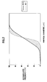
- FIG. 2 shows a relationship between particle diameter ( ⁇ m) and accumulated frequency (%) of the silicon carbide particles used in this embodiment.
- the x-axis indicates the logarithm of the particle diameter
- the y-axis indicates the accumulated frequency.
- the relationship between the particle diameter and accumulated frequency of the silicon carbide particles used in the embodiment has a lognormal distribution, and the relationship between the particle diameter and accumulated frequency is as shown in FIG. 2.
- the shaded area indicates an area of the logarithmic standard deviation of not less than 0.15 and not more than 0.4. Values of each component constituting two graphs shown in FIG. 2 are shown in Table 1.
- the organic binder is, for example, a methyl cellulose-based binder, an ethyl cellulose-based binder, polyvinyl alcohol, or the like.
- the kneaded raw material can be mixed with other additives when needed.
- Other additives can be, for example, a dispersing agent for promoting dispersion of the silicon carbide into water, a pore-forming agent for forming pores, and the like.
- the dispersing agent include ethylene glycol, dextrin, fatty-acid soap, and polyalcohol.
- Examples of the pore-forming agent include graphite, flour, starch, phenol resin, and polyethylene terephthalate.
- the kneaded raw material is extruded by extrusion into a molded body.
- the kneading method is not particularly limited, and it is possible to use a kneader such as a general kneader, a pressure kneader, a single shaft continuous extruder, double shaft continuous kneader/extruder, and a vacuum kneader.
- a kneader such as a general kneader, a pressure kneader, a single shaft continuous extruder, double shaft continuous kneader/extruder, and a vacuum kneader.
- the kneaded raw material is molded into a cylinder by the vacuum kneader and then molded into a honeycomb shape by a ram extruder.
- the raw material containing the silicon carbide particles, water, and the like is kneaded by a mixer 21, pressed into a die portion 23 by a extruder 22, and then extruded from the die portion 23 into a molded body 24.
- the kneaded raw material is pressed into a die 31, which is a part of the die portion 23 (FIG. 3), from a side of the mixer (the left side in FIG. 3) and gradually pressed into slits 32 on an outlet side, which form a honeycomb structure, to be spread in a cross-shape.
- the adjacent kneaded raw materials are compressed and joined into ribs 33, thus obtaining a unitary honeycomb structure as a whole.
- the molded body is dried. Specifically, for example, hot air is blown onto the molded body for drying.
- the drying method may be at least one selected from a group consisting microwave drying, dielectric drying, reduced pressure drying, vacuum drying, and freeze drying. For quick drying, a combination of hot air drying and microwave drying or dielectric drying is preferred.
- the honeycomb molded body obtained as described above is calcined into a calcined body.
- the calcining means an operation of fired and removing the organic substances (the binder, dispersing agent, pore-forming agent, and the like) within the molded body.
- the combustion temperature of the binder is about 200°C
- the combustion temperature of the pore-forming agent is about 300 to 900°C.
- Calcining temperature should be set to about 200 to 1000°C.
- Calcining time is not particularly limited, and usually one to ten hours.
- the calcined body obtained as described above is fired to obtain a porous honeycomb structure.
- the firing is an operation of sintering and densifying an aggregate grain raw material within the calcined body to secure predetermined strength.
- the firing temperature is about 1400 to 2400°C, and the firing temperature holding time is about 0.5 to 5 hours. To prevent oxidation, a non-oxidizing atmosphere is preferred.
- the powder of the raw material clogs the slits of the extruder die. Accordingly, many defects such as fractures and small holes are caused in the honeycomb ribs in the extruded body, which is not preferred.
- the average particle diameter is a 50% particle diameter measured by a Stokes liquid phase sedimentation method with an X-ray transmission type particle size distribution analyzer (for example, SediGraph 5000-2 made by Shimadzu Corporation or the like).
- the fluidity of the kneaded raw material injected into the extruder die is low to cause many defects in shape such as small holes generated in the honeycomb ribs and lacks of the honeycomb ribs, which is not preferred.
- the logarithmic standard deviation is not smaller than 0.17.
- the logarithmic standard deviation set to not smaller than 0.17 can largely prevent reduction in the fluidity and occurrence of shape defects.
- the logarithmic standard deviation of the particle size distribution is calculated as follows, for example.
- the logarithmic standard deviation SD can be thus calculated from measured values of D90 and D 10.
- the content of the silicon carbide is not less than 50 wt%.
- the binder metallic component or glass component
- the honeycomb structure excessively contracts by sintering, thus causing adverse effects such as reduction in porosity and average pore diameter.
- the contained raw materials may be silicon, clay, glass, and the like used as the binder and may be a raw material used as a sintering aid which includes at least one of B, C, Na, K, Al, Si, Ca, Cr, Mn, Fe, Ni, Sr, Y, Zr, and Ba.
- the proportion of particles with a particle diameter of not less than half the honeycomb rib thickness is not more than 5 wt%.
- the proportion of particles with a particle diameter of not less than half the honeycomb rib thickness that is, silt width
- the powder of the raw material clogs the slit, and causing many defects such as fractures and small holes in the honeycomb ribs.
- the silicon carbide had an average particle diameter of 2 ⁇ m, a logarithmic standard deviation of the particle size distribution of 0.19, and a proportion of particles with a particle diameter of not less than half the rib thickness of 0 wt%.
- the mixture was added to methyl cellulose as the organic binder, starch as the pore-forming agent, and a proper amount of water and mixed and kneaded by a vacuum kneader to prepare the kneaded raw material.
- This kneaded raw material was extruded using a die with the later-described cell shape, rib thickness, and cell density to be molded into a honeycomb shape and then dried by a combination of hot air drying and microwave drying, thus obtaining a honeycomb molded body.
- the end face shape (face where cells are opened) was a square with 35 mm ⁇ 35 mm, the length was 152 mm, the rib thickness was 203 ⁇ m, and the cell density was 300 cells per square inch.
- honeycomb molded body was calcined at about 550°C for 3 hours in atmosphere and then fired at about 1450°C for 2 hours in non-oxidizing atmosphere, thus obtaining porous honeycomb structure.
- a honeycomb structure was obtained in the same manner as Example 1 except that the silicon carbide powder had an average particle diameter of 20 ⁇ m, a logarithmic standard deviation of the particle size distribution 0.40, and a proportion of particles with a particle diameter of not less than half the rib thickness of 1.5 wt%.
- a honeycomb structure was obtained in the same manner as Example 1 except that the silicon carbide powder had a logarithmic standard deviation of the particle size distribution of 0.45.
- a honeycomb structure was obtained in the same manner as Example 1 except that the silicon carbide powder had an average particle diameter of 1.4 ⁇ m and a logarithmic standard deviation of the particle size distribution of 0.32.
- a honeycomb structure was obtained in the same manner as Example 1 except that the silicon carbide powder had an average particle diameter of 50 ⁇ m, a logarithmic standard deviation of the particle size distribution of 0.15, and a proportion of particles with a particle diameter of not less than half the rib thickness of 7.0 wt%.
- a honeycomb structure was obtained in the same manner as Example 1 except that the silicon carbide powder had an average particle diameter of 33 ⁇ m and a logarithmic standard deviation of the particle size distribution of 0.12.
- the silicon carbide had an average particle diameter of 35 ⁇ m, a logarithmic standard deviation of the particle size distribution of 0.15, and a proportion of particles with a particle diameter of not less than half the rib thickness of 0.3 wt%.
- the mixture was added to methyl cellulose as the organic binder, starch as the pore-forming agent, and a proper amount of water and mixed and kneaded by a vacuum kneader to prepare the kneaded raw material.
- the end face shape (face where cells are opened) was a square with 35 mm ⁇ 35 mm, the length was 152 mm, the rib thickness was 305 ⁇ m, and the cell density was 300 cells per square inch.
Landscapes
- Chemical & Material Sciences (AREA)
- Engineering & Computer Science (AREA)
- Ceramic Engineering (AREA)
- Manufacturing & Machinery (AREA)
- Organic Chemistry (AREA)
- Structural Engineering (AREA)
- Materials Engineering (AREA)
- Inorganic Chemistry (AREA)
- Mechanical Engineering (AREA)
- Press-Shaping Or Shaping Using Conveyers (AREA)
- Ceramic Products (AREA)
- Catalysts (AREA)
- Exhaust Gas After Treatment (AREA)
- Filtering Materials (AREA)
- Carbon And Carbon Compounds (AREA)
Abstract
Description
- The present invention relates to a method of manufacturing a honeycomb structure used as a filter for collecting tiny particles within gas emissions from an engine, a boiler, or the like, a catalyst support for supporting a catalyst which cleans up toxic substances in the gas emissions, or the like, and relates to silicon carbide particles for use in the method of manufacturing a honeycomb structure.
- As a raw material for manufacturing the aforementioned honeycomb structure used for the filter, catalyst support, or the like, silicon carbide particles excellent in heat and chemical resistance can be used. However, the honeycomb structure of silicon carbide manufactured by extrusion, which is a general method used for forming a honeycomb structure, has problems of high manufacturing costs and the like.
- To avoid these problems, there is a technology to reduce the manufacturing costs by sintering at comparatively low firing temperature (see, for example, Japanese Patent Laid-Open No. 2002-356383).
- One of the reasons why the honeycomb structure of silicon carbide is expensive is that the honeycomb structure obtained by injecting a kneaded raw material into a die and extruding the same is likely to have defects such as fractures and small holes caused in ribs thereof and has sometimes low productivity.
- Another one of the reasons for the expensive honeycomb structure of silicon carbide is, in addition to the occurrence of defects, that the silicon carbide raw material is expensive. A silicon carbide raw material generally used is for applications as abrasive powder and has a small range of particle size distribution as standardized by JIS R 6001. After the silicon carbide is classified in a manufacturing process, a large amount of material which does not meet the standard remains. This makes it difficult to reduce the costs.
- Therefore, an object of the present invention is to reduce the manufacturing costs of the porous honeycomb structure made of silicon carbide by allowing a material which has not hitherto been used to be used while maintaining a suitable incidence of the defects such as fractures and small holes of ribs, a suitable porosity, and the like.
- A first aspect of the present invention is a method of manufacturing a honeycomb structure, in which (1) water is added to silicon carbide particles and kneaded into a kneaded raw material, the silicon carbide having an average particle diameter of not less than 2 µm and not more than a honeycomb rib thickness × 0.23 and with a logarithmic standard deviation of a particle size distribution of not less than 0.15 and not more than 0.40; (2) the kneaded raw material is extruded by extrusion into a honeycomb extruded body; and (3) the extruded body is dried, calcined, and fired.
-
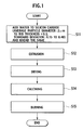
- FIG. 1 is a flowchart showing a flow of a process of an embodiment.
- FIG. 2 is a view showing a relationship between particle diameter (µm) and accumulated frequency (%) of silicon carbide particles used in this embodiment.
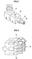
- FIG. 3 is a perspective view schematically showing a constitution of a mixer, extruder, and a die portion according to the embodiment of the present invention.
- FIG. 4 is a perspective view showing an internal structure of the die portion shown in FIG. 3.
- Hereinafter, a description is given of an embodiment of the present invention with reference to the drawings. The present invention should not be limited to the embodiment.
- As shown in FIG. 1, in this embodiment, first, water is added to silicon carbide particles and then kneaded into a kneaded raw material. Herein, the silicon carbide has an average diameter of not less than 2 µm and not more than a honeycomb rib thickness × 0.23 and a logarithmic standard deviation of a particle size distribution of not less than 0.15 and not more than 0.40(step S11). Next, the kneaded raw material is extruded by extrusion into a honeycomb-shaped extruded body (step S12). Subsequently, the extruded body is dried (step S 13), further calcined (step S14), and then fired (step S15).
- First, water, an organic binder, and the like are added to the silicon carbide particles and then kneaded to prepare the kneaded raw material.
- The silicon carbide particles have an average diameter of not less than 2 µm and not more than a honeycomb rib thickness × 0.23 and a logarithmic standard deviation of a particle size distribution of not less than 0.15 and not more than 0.40. The silicon carbide particles are composed of one type of raw material or are prepared by mixing several types of raw materials so as to satisfy the aforementioned ranges.
- FIG. 2 shows a relationship between particle diameter (µm) and accumulated frequency (%) of the silicon carbide particles used in this embodiment. Herein, the x-axis indicates the logarithm of the particle diameter, and the y-axis indicates the accumulated frequency. The relationship between the particle diameter and accumulated frequency of the silicon carbide particles used in the embodiment has a lognormal distribution, and the relationship between the particle diameter and accumulated frequency is as shown in FIG. 2. In FIG. 2, the shaded area indicates an area of the logarithmic standard deviation of not less than 0.15 and not more than 0.4. Values of each component constituting two graphs shown in FIG. 2 are shown in Table 1.
TABLE 1 SD=0.40 SD=0.15 PARTICLE DIAMETER [µm] ACCUMULATED FREQUENCY PARTICLE DIAMETER [µm] ACCUMULATED FREQUENCY 1019.5 100.0 1019.5 100.0 890.1 100.0 890.1 100.0 777.1 100.0 777.1 100.0 678.5 100.0 678.5 100.0 592.3 100.0 592.3 100.0 517.2 100.0 517.2 100.0 451.5 100.0 451.5 100.0 394.2 100.0 394.2 100.0 344.2 99.9 344.2 100.0 300.5 99.8 300.5 100.0 262.3 99.5 262.3 100.0 229.0 99.6 229.0 100.0 200.0 99.2 200.0 100.0 174.6 98.0 174.6 100.0 152.4 97.0 152.4 100.0 133.1 95.0 133.1 99.9 116.2 93.0 116.2 99.7 101.4 89.8 101.4 99.2 88.6 86.0 88.6 98.3 77.3 82.0 77.3 96.5 67.5 78.0 67.5 93.4 59.0 72.0 59.0 88.2 51.5 67.0 51.5 80.3 44.9 62.0 44.9 70.6 39.2 57.0 39.2 57.9 34.3 52.0 34.3 42.8 29.9 46.0 29.9 28.2 26.1 41.0 26.1 16.4 22.8 36.0 22.8 8.9 19.9 31.5 19.9 4.8 17.4 7.0 17.4 2.6 15.2 22.0 15.2 1.4 13.2 17.5 13.2 0.7 11.6 13.3 11.6 0.3 10.1 9.5 10.1 0.1 8.8 6.6 8.8 0.0 7.7 4.6 7.7 0.0 6.7 3.3 6.7 0.0 5.9 2.5 5.9 0.0 5.1 1.9 5.1 0.0 4.5 1.6 4.5 0.0 3.9 1.4 3.9 0.0 3.4 1.2 3.4 0.0 3.0 1.0 3.0 0.0 2.6 0.9 2.6 0.0 2.3 0.8 2.3 0.0 2.0 0.7 2.0 0.0 1.7 0.6 1.7 0.0 1.5 0.5 1.5 0.0 1.3 0.4 1.3 0.0 1.2 0.3 1.2 0.0 1.0 0.2 1.0 0.0 0.9 0.2 0.9 0.0 0.8 0.1 0.8 0.0 - The organic binder is, for example, a methyl cellulose-based binder, an ethyl cellulose-based binder, polyvinyl alcohol, or the like.
- The kneaded raw material can be mixed with other additives when needed. Other additives can be, for example, a dispersing agent for promoting dispersion of the silicon carbide into water, a pore-forming agent for forming pores, and the like. Examples of the dispersing agent include ethylene glycol, dextrin, fatty-acid soap, and polyalcohol. Examples of the pore-forming agent include graphite, flour, starch, phenol resin, and polyethylene terephthalate.
- Next, the kneaded raw material is extruded by extrusion into a molded body. The kneading method is not particularly limited, and it is possible to use a kneader such as a general kneader, a pressure kneader, a single shaft continuous extruder, double shaft continuous kneader/extruder, and a vacuum kneader. For example, the kneaded raw material is molded into a cylinder by the vacuum kneader and then molded into a honeycomb shape by a ram extruder.
- For example, as shown FIG. 3, the raw material containing the silicon carbide particles, water, and the like is kneaded by a
mixer 21, pressed into adie portion 23 by aextruder 22, and then extruded from thedie portion 23 into a moldedbody 24. - As shown in FIG. 4, the kneaded raw material is pressed into a
die 31, which is a part of the die portion 23 (FIG. 3), from a side of the mixer (the left side in FIG. 3) and gradually pressed intoslits 32 on an outlet side, which form a honeycomb structure, to be spread in a cross-shape. The adjacent kneaded raw materials are compressed and joined intoribs 33, thus obtaining a unitary honeycomb structure as a whole. - Next, the molded body is dried. Specifically, for example, hot air is blown onto the molded body for drying. The drying method may be at least one selected from a group consisting microwave drying, dielectric drying, reduced pressure drying, vacuum drying, and freeze drying. For quick drying, a combination of hot air drying and microwave drying or dielectric drying is preferred.
- Furthermore, the honeycomb molded body obtained as described above is calcined into a calcined body. The calcining means an operation of fired and removing the organic substances (the binder, dispersing agent, pore-forming agent, and the like) within the molded body. Generally, the combustion temperature of the binder is about 200°C, and the combustion temperature of the pore-forming agent is about 300 to 900°C. Calcining temperature should be set to about 200 to 1000°C. Calcining time is not particularly limited, and usually one to ten hours.
- Finally, the calcined body obtained as described above is fired to obtain a porous honeycomb structure. The firing is an operation of sintering and densifying an aggregate grain raw material within the calcined body to secure predetermined strength. The firing temperature is about 1400 to 2400°C, and the firing temperature holding time is about 0.5 to 5 hours. To prevent oxidation, a non-oxidizing atmosphere is preferred.
- Reasons for the average diameter of the silicon carbide particles of not less than 2 µm and not more than the honeycomb rib thickness × 0.23 and the logarithmic standard deviation of the particle size distribution of not less than 0.15 and not more than 0.40 are as follows.
- When the average particle diameter is less than 2 µm, the porosity of the
ribs 33 of the honeycomb structure obtained by firing is less than 40% due to an effect of filling voids with the tiny particles, thus increasing pressure loss of emitted exhaust gas with respect to the exhaust gas entering the honeycomb structure. In addition, the heat capacity thereof is increased, which is not preferred. - When the average particle size is larger than the honeycomb rib thickness × 0.23, the powder of the raw material clogs the slits of the extruder die. Accordingly, many defects such as fractures and small holes are caused in the honeycomb ribs in the extruded body, which is not preferred.
- The average particle diameter is a 50% particle diameter measured by a Stokes liquid phase sedimentation method with an X-ray transmission type particle size distribution analyzer (for example, SediGraph 5000-2 made by Shimadzu Corporation or the like).
- When the logarithmic standard deviation is smaller than 0.15, the fluidity of the kneaded raw material injected into the extruder die is low to cause many defects in shape such as small holes generated in the honeycomb ribs and lacks of the honeycomb ribs, which is not preferred.
- Moreover, it is preferable that the logarithmic standard deviation is not smaller than 0.17. The logarithmic standard deviation set to not smaller than 0.17 can largely prevent reduction in the fluidity and occurrence of shape defects.
- When the logarithmic standard deviation is larger than 0.4, in other words, when the particle size widely varies, small particles enter gaps between large particles to fill the pores of the honeycomb ribs, and the porosity of the sintered body is reduced, which is not preferred.
- The logarithmic standard deviation of the particle size distribution is calculated as follows, for example.
- First, the particle sizes and the accumulated frequency of each particle size are calculated by a laser diffraction method, a precipitation method, an electrical resistance method, or the like. 80% of data fall within a range of the accumulated frequency between 10% and 90%. According to the lognormal distribution table, 80% of the data fall between ±1.28σ around an average. Accordingly, the following equation is established when D10 is a particle diameter corresponding to an accumulated frequency of 10%, D90 is a particle diameter corresponding to an accumulated frequency of 90%, and SD is the logarithmic standard deviation.

Therefore, the following equation is established.
- The logarithmic standard deviation SD can be thus calculated from measured values of D90 and D 10.
- Preferably, the content of the silicon carbide is not less than 50 wt%. When the content of the silicon carbide is less than 50 wt%, for example, in the case where another contained raw material is used as a binder for the silicon carbide as the aggregate, the binder (metallic component or glass component) is too much, and the honeycomb structure excessively contracts by sintering, thus causing adverse effects such as reduction in porosity and average pore diameter. The contained raw materials may be silicon, clay, glass, and the like used as the binder and may be a raw material used as a sintering aid which includes at least one of B, C, Na, K, Al, Si, Ca, Cr, Mn, Fe, Ni, Sr, Y, Zr, and Ba.
- Furthermore, preferably, the proportion of particles with a particle diameter of not less than half the honeycomb rib thickness is not more than 5 wt%. When the proportion of particles with a particle diameter of not less than half the honeycomb rib thickness (that is, silt width) is more than 5 wt%, the powder of the raw material clogs the slit, and causing many defects such as fractures and small holes in the honeycomb ribs.
- Twenty parts by weight of silicon as the binder was added to 80 parts by weight of the silicon carbide. Herein, the silicon carbide had an average particle diameter of 2 µm, a logarithmic standard deviation of the particle size distribution of 0.19, and a proportion of particles with a particle diameter of not less than half the rib thickness of 0 wt%. The mixture was added to methyl cellulose as the organic binder, starch as the pore-forming agent, and a proper amount of water and mixed and kneaded by a vacuum kneader to prepare the kneaded raw material.
- This kneaded raw material was extruded using a die with the later-described cell shape, rib thickness, and cell density to be molded into a honeycomb shape and then dried by a combination of hot air drying and microwave drying, thus obtaining a honeycomb molded body.
- In the entire shape of the obtained honeycomb molded body, the end face shape (face where cells are opened) was a square with 35 mm × 35 mm, the length was 152 mm, the rib thickness was 203 µm, and the cell density was 300 cells per square inch.
- Thereafter, the honeycomb molded body was calcined at about 550°C for 3 hours in atmosphere and then fired at about 1450°C for 2 hours in non-oxidizing atmosphere, thus obtaining porous honeycomb structure.
- A honeycomb structure was obtained in the same manner as Example 1 except that the silicon carbide powder had an average particle diameter of 10 µm, a logarithmic standard deviation of the particle size distribution 0.28, and a proportion of particles with a particle diameter of not less than half the rib thickness of 0.2%.
- A honeycomb structure was obtained in the same manner as Example 1 except that the silicon carbide powder had an average particle diameter of 20 µm, a logarithmic standard deviation of the particle size distribution 0.40, and a proportion of particles with a particle diameter of not less than half the rib thickness of 1.5 wt%.
- A honeycomb structure was obtained in the same manner as Example 1 except that the silicon carbide powder had a logarithmic standard deviation of the particle size distribution of 0.45.
- A honeycomb structure was obtained in the same manner as Example 1 except that the silicon carbide powder had an average particle diameter of 1.4 µm and a logarithmic standard deviation of the particle size distribution of 0.32.
- A honeycomb structure was obtained in the same manner as Example 1 except that the silicon carbide powder had an average particle diameter of 50 µm, a logarithmic standard deviation of the particle size distribution of 0.15, and a proportion of particles with a particle diameter of not less than half the rib thickness of 7.0 wt%.
- A honeycomb structure was obtained in the same manner as Example 1 except that the silicon carbide powder had an average particle diameter of 33 µm and a logarithmic standard deviation of the particle size distribution of 0.12.
- Twenty parts by weight of silicon as the binder was added to 80 parts by weight of the silicon carbide. The silicon carbide had an average particle diameter of 35 µm, a logarithmic standard deviation of the particle size distribution of 0.15, and a proportion of particles with a particle diameter of not less than half the rib thickness of 0.3 wt%. The mixture was added to methyl cellulose as the organic binder, starch as the pore-forming agent, and a proper amount of water and mixed and kneaded by a vacuum kneader to prepare the kneaded raw material.
- This kneaded raw material was extruded using a die with the later-described cell shape, rib thickness, and cell density to be molded into a honeycomb shape and then dried by a combination of hot air drying and microwave drying, thus obtaining a honeycomb molded body.
- In the entire shape of the obtained honeycomb molded body, the end face shape (face where cells are opened) was a square with 35 mm × 35 mm, the length was 152 mm, the rib thickness was 305 µm, and the cell density was 300 cells per square inch.
- Thereafter, the honeycomb molded body was calcined at about 550°C for 3 hours in atmosphere and then fired at about 1450°C for 2 hours in non-oxidizing atmosphere, thus obtaining a porous honeycomb structure.
- A honeycomb structure was obtained in the same manner as Example 4 except that the silicon carbide powder had an average particle diameter of 60 µm, a logarithmic standard deviation of the particle size distribution of 0.19, and a proportion of particles with a particle diameter of not less than half the rib thickness of 2.8 wt%.
- A honeycomb structure was obtained in the same manner as Example 4 except that the silicon carbide powder had an average particle diameter of 70 µm, a logarithmic standard deviation of the particle size distribution of 0.17, and a proportion of particles with a particle diameter of not less than half the rib thickness of 5.0 wt%.
- A honeycomb structure was obtained in the same manner as Example 4 except that the silicon carbide powder had a logarithmic standard deviation of the particle size distribution of 0.12 and a proportion of particles with a particle diameter of not less than half the rib thickness of 0 wt%.
- A honeycomb structure was obtained in the same manner as Example 4 except that the silicon carbide powder had an average particle diameter of 72 µm, a logarithmic standard deviation of the particle size distribution of 0.17, and a proportion of particles with a particle diameter of not less than half the rib thickness of 6.5 wt%.
- A honeycomb structure was obtained in the same manner as Example 4 except that the silicon carbide powder had an average particle diameter of 1.4 µm, a logarithmic standard deviation of the particle size distribution of 0.32, and a proportion of particles with a particle diameter of not less than half the rib thickness of 0 wt%.
- A honeycomb structure was obtained in the same manner as Example 4 except that the silicon carbide powder had an average particle diameter of 32 µm, a logarithmic standard deviation of the particle size distribution of 0.44, and a proportion of particles with a particle diameter of not less than half the rib thickness of 4.0 wt%.
- Twenty parts by weight of silicon as the binder was added to 80 parts by weight of the silicon carbide. The silicon carbide had an average particle diameter of 40 µm, a logarithmic standard deviation of the particle size distribution of 0.25, and a proportion of particles with a particle diameter of not less than half the rib thickness of 1.6 wt%. The mixture was added to methyl cellulose as the organic binder, starch as the pore-forming agent, and a proper amount of water and mixed and kneaded by a vacuum kneader to prepare the kneaded raw material.
- This kneaded raw material was extruded using a die with the later-described cell shape, rib thickness, and cell density to be molded into a honeycomb shape and then dried by a combination of hot air drying and microwave drying, thus obtaining a honeycomb molded body.
- In the entire shape of the obtained honeycomb molded body, the end face shape (face where cells are opened) was a square with 35 mm × 35 mm, the length was 254 mm, the rib thickness was 381 µm, and the cell density was 200 cells per square inch.
- Thereafter, the honeycomb molded body was calcined at about 550°C for 3 hours in atmosphere and then fired at about 1450°C for 2 hours in non-oxidizing atmosphere, thus obtaining a porous honeycomb structure.
- A honeycomb structure was obtained in the same manner as Example 7 except that the silicon carbide powder had an average particle diameter of 87 µm, a logarithmic standard deviation of the particle size distribution of 0.15, and a proportion of particles with a particle diameter of not less than half the rib thickness of 5.0 wt%.
- A honeycomb structure was obtained in the same manner as Example 7 except that the silicon carbide powder had an average particle diameter of 90 µm, a logarithmic standard deviation of the particle size distribution of 0.16, and a proportion of particles with a particle diameter of not less than half the rib thickness of 10.6 wt%.
- A honeycomb structure was obtained in the same manner as Example 7 except that the silicon carbide powder had an average particle diameter of 65 µm, a logarithmic standard deviation of the particle size distribution of 0.14, and a proportion of particles with a particle diameter of not less than half the rib thickness of 5.0 wt%.
- A honeycomb structure was obtained in the same manner as Example 7 except that the silicon carbide powder had an average particle diameter of 36 µm, a logarithmic standard deviation of the particle size distribution of 0.43, and a proportion of particles with a particle diameter of not less than half the rib thickness of 4.5 wt%.
- A hundred parts by weight of the silicon carbide, which had an average particle diameter of 12 µm, a logarithmic standard deviation of the particle size distribution of 0.25, and a proportion of particles with a particle diameter of not less than half the rib thickness of 0 wt%, was added with methyl cellulose as the organic binder, iron oxide and yttrium oxide as the sintering aid, starch as the pore-forming agent, and a proper amount of water and mixed and kneaded by the vacuum kneader to prepare the kneaded raw material.
- This kneaded raw material was extruded using a die with the later-described cell shape, rib thickness, and cell density to be molded into a honeycomb shape and then dried by a combination of hot air drying and microwave drying, thus obtaining a honeycomb molded body.
- In the entire shape of the obtained honeycomb molded body, the end face shape (face where cells are opened) was a square with 35 mm × 35 mm, the length was 254 mm, the rib thickness was 381 µm, and the cell density was 200 cells per square inch.
- Thereafter, the honeycomb molded body was calcined at about 550°C for 3 hours in atmosphere and then fired at about 2300°C for 2 hours in non-oxidizing atmosphere, thus obtaining a porous honeycomb structure.
- A honeycomb structure was obtained in the same manner as Example 9 except that the silicon carbide powder had an average particle diameter of 90 µm, a logarithmic standard deviation of the particle size distribution of 0.16, and a proportion of particles with a particle diameter of not less than half the rib thickness of 10.6 wt%.
- A honeycomb structure was obtained in the same manner as Example 9 except that the silicon carbide powder had an average particle diameter of 65 µm, a logarithmic standard deviation of the particle size distribution of 0.14, and a proportion of particles with a particle diameter of not less than half the rib thickness of 5.0 wt%.
- A honeycomb structure was obtained in the same manner as Example 9 except that the silicon carbide powder had an average particle diameter of 36 µm, a logarithmic standard deviation of the particle size distribution of 0.43, and a proportion of particles with a particle diameter of not less than half the rib thickness of 4.5 wt%.
- A honeycomb structure was obtained in the same manner as Example 9 except that the silicon carbide powder had an average particle diameter of 1.4 µm, a logarithmic standard deviation of the particle size distribution of 0.32, and a proportion of particles with a particle diameter of not less than half the rib thickness of 0 wt%.
- Twenty parts by weight of glass frit was added to 80 parts by weight of the silicon carbide. The silicon carbide had an average particle diameter of 35 µm, a logarithmic standard deviation of the particle size distribution of 0.15, and a proportion of particles with a particle diameter of not less than half the rib thickness of 0.3 wt%. The mixture was added to methyl cellulose as the organic binder, starch as the pore-forming agent, and a proper amount of water and mixed and kneaded by the vacuum kneader to prepare the kneaded raw material.
- This kneaded raw material was extruded using a die with the later-described cell shape, rib thickness, and cell density to be molded into a honeycomb shape and then dried by a combination of hot air drying and microwave drying, thus obtaining a honeycomb molded body. In the entire shape of the obtained honeycomb molded body, the end face shape (face where cells are opened) was a square with 35 mm × 35 mm, the length was 254 mm, the rib thickness was 305 µm, and the cell density was 300 cells per square inch.
- Thereafter, the honeycomb molded body was calcined at about 550°C for 3 hours in atmosphere and then fired at about 1450°C for 2 hours in non-oxidizing atmosphere, thus obtaining a porous honeycomb structure.
- A honeycomb structure was obtained in the same manner as Example 10 except that the silicon carbide powder had a logarithmic standard deviation of the particle size distribution of 0.12 and a proportion of particles with a particle diameter of not less than half the rib thickness of 0 wt%.
- A honeycomb structure was obtained in the same manner as Example 10 except that the silicon carbide powder had an average particle diameter of 72 µm, a logarithmic standard deviation of the particle size distribution of 0.17, and a proportion of particles with a particle diameter of not less than half the rib thickness of 6.5 wt%.
- A honeycomb structure was obtained in the same manner as Example 10 except that the silicon carbide powder had an average particle diameter of 32 µm, a logarithmic standard deviation of the particle size distribution of 0.44, and a proportion of particles with a particle diameter of not less than half the rib thickness of 4.0 wt%.
- Examples 1 to 10 and Comparative Examples 1 to 19 were evaluated in terms of the moldability of the honeycomb molded body and the porosity of the porous honeycomb structure. The moldability of the honeycomb molded body was visually evaluated, and the porosity of the porous honeycomb structure was evaluated by a mercury injection method. Results thereof are shown in Table 2. Note that Defect (1) indicates that many defects of fractures and improper molding due to clogging of the die were caused, and Defect (2) indicates that many defects such as small holes, fractures, and the like were caused by the low fluidity of the kneaded material within the die orifice.

- The honeycomb molded bodies of Examples 1 to 5, 7, 9, and 10 had no defects in shape are caused and no clogging of the die. The honeycomb molded bodies of Examples 6 and 8 had no defects in shape, and the incidence of clogging of the die was very low at about 1 %. The porosities of the honeycomb structures of Examples 1 to 10 were not smaller than 40%.
- On the contrary, the porosities of the honeycomb structures of Comparative Examples 1, 2, 7, 8, 11, 14, 15, and 18 were reduced to 30 to 34%. In the honeycomb structures of Comparative Examples 3, 6, 9, 12, and 17, the die was clogged in molding, and many fracture defects were caused.
- In each of the honeycomb structures of Comparative Examples 4, 5, 10, 13, and 16, the kneaded material within the die in molding is low in fluidity, and many defects such as small holes were caused.
- As described above, according to the present invention, it is possible to avoid defects in shape of the extruded body and the reduction in porosity of the honeycomb ribs by controlling the average particle diameter and the logarithmic standard deviation of the particle size distribution.
Claims (5)
- A method of manufacturing a honeycomb structure, comprising:adding water to silicon carbide particles and kneading the same into a kneaded raw material, the silicon carbide having an average particle diameter of not less than 2 µm and not more than a honeycomb rib thickness × 0.23 and with a logarithmic standard deviation of a particle size distribution of not less than 0.15 and not more than 0.40;extruding the kneaded raw material by extrusion into a honeycomb extruded body; anddrying, calcining, and firing the extruded body.
- The method of manufacturing a honeycomb structure according to claim 1, wherein the logarithmic standard deviation of the particle size distribution was not less than 0.17 and not more than 0.40.
- The method of manufacturing a honeycomb structure according to any one of claims 1 and 2, wherein a content of the silicon carbide is not less than 50 wt%.
- The method of manufacturing a honeycomb structure according to any one of claims 1 to 3, wherein a proportion of particles with a particle diameter of not less than half the honeycomb rib thickness is less than 5 wt%.
- Silicon carbide particles for manufacturing a honeycomb structure by extrusion, wherein
an average particle diameter is not less than 2 µm and not more than a honeycomb rib thickness × 0.23 and a logarithmic standard deviation of a particle size distribution is not less than 0.15 and not more than 0.40.
Priority Applications (1)
| Application Number | Priority Date | Filing Date | Title |
|---|---|---|---|
| PL04745363T PL1640351T3 (en) | 2003-05-29 | 2004-05-27 | Method for producing honeycomb structure |
Applications Claiming Priority (2)
| Application Number | Priority Date | Filing Date | Title |
|---|---|---|---|
| JP2003152379 | 2003-05-29 | ||
| PCT/JP2004/007257 WO2004106265A1 (en) | 2003-05-29 | 2004-05-27 | Method for producing honeycomb structure and silicon carbide particles used for producing honeycomb structure |
Publications (3)
| Publication Number | Publication Date |
|---|---|
| EP1640351A1 true EP1640351A1 (en) | 2006-03-29 |
| EP1640351A4 EP1640351A4 (en) | 2009-11-11 |
| EP1640351B1 EP1640351B1 (en) | 2013-04-24 |
Family
ID=33487254
Family Applications (1)
| Application Number | Title | Priority Date | Filing Date |
|---|---|---|---|
| EP04745363.4A Expired - Lifetime EP1640351B1 (en) | 2003-05-29 | 2004-05-27 | Method for producing honeycomb structure |
Country Status (6)
| Country | Link |
|---|---|
| US (1) | US7569201B2 (en) |
| EP (1) | EP1640351B1 (en) |
| JP (1) | JPWO2004106265A1 (en) |
| KR (1) | KR20060017739A (en) |
| PL (1) | PL1640351T3 (en) |
| WO (1) | WO2004106265A1 (en) |
Families Citing this family (7)
| Publication number | Priority date | Publication date | Assignee | Title |
|---|---|---|---|---|
| KR20060017739A (en) * | 2003-05-29 | 2006-02-27 | 니뽄 가이시 가부시키가이샤 | Method for producing honeycomb structure and silicon carbide particles for producing honeycomb structure |
| US8178019B2 (en) * | 2006-09-28 | 2012-05-15 | Hitachi Metals, Ltd. | Method and apparatus for producing ceramic honeycomb structure |
| JP5149032B2 (en) * | 2008-02-19 | 2013-02-20 | 東京窯業株式会社 | Honeycomb structure |
| DE102008001125A1 (en) * | 2008-04-11 | 2009-10-15 | Evonik Degussa Gmbh | Copolyamide powder as a pore-forming agent in regenerable ceramic particle filters |
| WO2014003836A1 (en) * | 2012-06-27 | 2014-01-03 | Dow Global Technologies Llc | Improved method of making porous plugs in ceramic honeycomb filter |
| US9393674B2 (en) * | 2013-04-04 | 2016-07-19 | Smith International, Inc. | Cemented carbide composite for a downhole tool |
| EP4230280B8 (en) | 2021-03-26 | 2026-07-15 | Mirai Casting America, Inc. | Silicon carbide-based ceramic honeycomb structure and production method therefor |
Family Cites Families (15)
| Publication number | Priority date | Publication date | Assignee | Title |
|---|---|---|---|---|
| JP2818039B2 (en) * | 1991-03-06 | 1998-10-30 | シャープ株式会社 | Air purifier also serves as a heater |
| DE4214725C2 (en) * | 1992-05-04 | 1995-04-20 | Starck H C Gmbh Co Kg | Fine-particle non-oxide ceramic powder |
| DE19727115C2 (en) * | 1996-07-01 | 2001-08-02 | Fraunhofer Ges Forschung | Porous silicon carbide ceramics and process for their production |
| JP4267723B2 (en) * | 1998-08-06 | 2009-05-27 | 株式会社ブリヂストン | Method for producing particulate compound |
| JP2000351614A (en) * | 1999-06-10 | 2000-12-19 | Bridgestone Corp | Silicon carbide powder and its production |
| FR2796638B1 (en) * | 1999-07-21 | 2001-09-14 | Ceramiques Tech Et Ind S A | HONEYCOMB MONOLITH STRUCTURE IN POROUS CERAMIC MATERIAL, AND USE AS A PARTICLE FILTER |
| JP2001151579A (en) | 1999-11-26 | 2001-06-05 | Ngk Insulators Ltd | SiC porous body and method for producing the same |
| JP4468541B2 (en) | 2000-03-17 | 2010-05-26 | 日本碍子株式会社 | Method for producing recrystallized SiC |
| JP4464568B2 (en) * | 2001-02-02 | 2010-05-19 | 日本碍子株式会社 | Honeycomb structure and manufacturing method thereof |
| WO2002070433A1 (en) * | 2001-03-02 | 2002-09-12 | Ngk Insulators,Ltd. | Honeycomb structure |
| JP4307781B2 (en) | 2001-03-30 | 2009-08-05 | 日本碍子株式会社 | Silicon carbide based porous material and method for producing the same |
| WO2002081054A1 (en) * | 2001-04-09 | 2002-10-17 | Corning Incorporated | Porous filter body and method |
| JP4700835B2 (en) * | 2001-05-01 | 2011-06-15 | 株式会社ブリヂストン | Silicon carbide powder, method for producing the same, and silicon carbide sintered body |
| US20030072917A1 (en) * | 2001-10-11 | 2003-04-17 | Ewen Anthony Campbell | Vacuum formed thermoplastic films and articles therefrom |
| KR20060017739A (en) * | 2003-05-29 | 2006-02-27 | 니뽄 가이시 가부시키가이샤 | Method for producing honeycomb structure and silicon carbide particles for producing honeycomb structure |
-
2004
- 2004-05-27 KR KR1020057004733A patent/KR20060017739A/en not_active Ceased
- 2004-05-27 US US10/527,440 patent/US7569201B2/en not_active Expired - Lifetime
- 2004-05-27 WO PCT/JP2004/007257 patent/WO2004106265A1/en not_active Ceased
- 2004-05-27 PL PL04745363T patent/PL1640351T3/en unknown
- 2004-05-27 EP EP04745363.4A patent/EP1640351B1/en not_active Expired - Lifetime
- 2004-05-27 JP JP2005506489A patent/JPWO2004106265A1/en active Pending
Also Published As
| Publication number | Publication date |
|---|---|
| PL1640351T3 (en) | 2013-09-30 |
| EP1640351A4 (en) | 2009-11-11 |
| WO2004106265A1 (en) | 2004-12-09 |
| KR20060017739A (en) | 2006-02-27 |
| US20060154068A1 (en) | 2006-07-13 |
| JPWO2004106265A1 (en) | 2006-07-20 |
| US7569201B2 (en) | 2009-08-04 |
| EP1640351B1 (en) | 2013-04-24 |
Similar Documents
| Publication | Publication Date | Title |
|---|---|---|
| EP1997788B1 (en) | Process for producing a cordierite-based honeycomb structure | |
| EP2832712B1 (en) | Porous material, honeycomb structure | |
| EP2668990B1 (en) | Honeycomb structure | |
| EP1657039B1 (en) | Method for manufacturing a ceramic honeycomb filter | |
| EP2957548B1 (en) | Honeycomb structure | |
| EP2604323A1 (en) | Honeycomb filter and production method for same | |
| EP2784042B1 (en) | Porous material and honeycomb structure | |
| US6593261B2 (en) | Silicon nitride porous body and its production process | |
| CN104987123A (en) | Honeycomb manufacturing method using ground nut shells and honeycomb body produced thereby | |
| US12415154B2 (en) | Honeycomb filter | |
| DE102017009848B4 (en) | Pore-formed material, honeycomb structure and process for producing a fired porous material | |
| EP2641644B1 (en) | Honeycomb structure and manufacturing method of honeycomb structure | |
| EP2737946A1 (en) | Honeycomb Catalyst Body | |
| US11359528B2 (en) | Honeycomb filter | |
| JP2004315346A (en) | Honeycomb structure | |
| US20210094885A1 (en) | Reduced anisotropy aluminum titanate-cordierite ceramic bodies, batch mixtures including spherical alumina, and methods of manufacturing ceramic bodies therefrom | |
| EP1428809B1 (en) | Process for production of formed honeycomb body | |
| EP1679294A1 (en) | Method for manufacturing silicon carbide based honeycomb structure and silicon carbide based honeycomb structure | |
| EP1808228A1 (en) | Honeycomb structure, method for production thereof and exhaust gas purification device | |
| EP1787968B1 (en) | Method for manufacturing porous article, porous article and honeycomb structure | |
| EP1640351B1 (en) | Method for producing honeycomb structure | |
| CN111718190A (en) | Method for manufacturing ceramic honeycomb structure | |
| US20230356131A1 (en) | Honeycomb filter | |
| EP2107046A2 (en) | Porous honeycomb structure body and method of manufacturing the same | |
| EP2070889B1 (en) | A silicon carbide-based porous body and manufacturing method thereof |
Legal Events
| Date | Code | Title | Description |
|---|---|---|---|
| PUAI | Public reference made under article 153(3) epc to a published international application that has entered the european phase |
Free format text: ORIGINAL CODE: 0009012 |
|
| 17P | Request for examination filed |
Effective date: 20050405 |
|
| AK | Designated contracting states |
Kind code of ref document: A1 Designated state(s): DE FR PL |
|
| DAX | Request for extension of the european patent (deleted) | ||
| RBV | Designated contracting states (corrected) |
Designated state(s): DE FR PL |
|
| RIC1 | Information provided on ipc code assigned before grant |
Ipc: C04B 35/622 20060101AFI20041213BHEP Ipc: C04B 35/626 20060101ALI20090930BHEP Ipc: C01B 31/36 20060101ALI20090930BHEP |
|
| A4 | Supplementary search report drawn up and despatched |
Effective date: 20091013 |
|
| 17Q | First examination report despatched |
Effective date: 20100331 |
|
| GRAP | Despatch of communication of intention to grant a patent |
Free format text: ORIGINAL CODE: EPIDOSNIGR1 |
|
| GRAS | Grant fee paid |
Free format text: ORIGINAL CODE: EPIDOSNIGR3 |
|
| GRAA | (expected) grant |
Free format text: ORIGINAL CODE: 0009210 |
|
| AK | Designated contracting states |
Kind code of ref document: B1 Designated state(s): DE FR PL |
|
| REG | Reference to a national code |
Ref country code: DE Ref legal event code: R096 Ref document number: 602004041869 Country of ref document: DE Effective date: 20130620 |
|
| REG | Reference to a national code |
Ref country code: PL Ref legal event code: T3 |
|
| PLBE | No opposition filed within time limit |
Free format text: ORIGINAL CODE: 0009261 |
|
| STAA | Information on the status of an ep patent application or granted ep patent |
Free format text: STATUS: NO OPPOSITION FILED WITHIN TIME LIMIT |
|
| 26N | No opposition filed |
Effective date: 20140127 |
|
| REG | Reference to a national code |
Ref country code: DE Ref legal event code: R097 Ref document number: 602004041869 Country of ref document: DE Effective date: 20140127 |
|
| REG | Reference to a national code |
Ref country code: FR Ref legal event code: PLFP Year of fee payment: 13 |
|
| REG | Reference to a national code |
Ref country code: FR Ref legal event code: PLFP Year of fee payment: 14 |
|
| REG | Reference to a national code |
Ref country code: FR Ref legal event code: PLFP Year of fee payment: 15 |
|
| PGFP | Annual fee paid to national office [announced via postgrant information from national office to epo] |
Ref country code: FR Payment date: 20200414 Year of fee payment: 17 |
|
| PGFP | Annual fee paid to national office [announced via postgrant information from national office to epo] |
Ref country code: PL Payment date: 20200416 Year of fee payment: 17 |
|
| PGFP | Annual fee paid to national office [announced via postgrant information from national office to epo] |
Ref country code: DE Payment date: 20210427 Year of fee payment: 18 |
|
| PG25 | Lapsed in a contracting state [announced via postgrant information from national office to epo] |
Ref country code: FR Free format text: LAPSE BECAUSE OF NON-PAYMENT OF DUE FEES Effective date: 20210531 |
|
| REG | Reference to a national code |
Ref country code: DE Ref legal event code: R119 Ref document number: 602004041869 Country of ref document: DE |
|
| PG25 | Lapsed in a contracting state [announced via postgrant information from national office to epo] |
Ref country code: PL Free format text: LAPSE BECAUSE OF NON-PAYMENT OF DUE FEES Effective date: 20210527 |
|
| PG25 | Lapsed in a contracting state [announced via postgrant information from national office to epo] |
Ref country code: DE Free format text: LAPSE BECAUSE OF NON-PAYMENT OF DUE FEES Effective date: 20221201 |