EP1787968B1 - Method for manufacturing porous article, porous article and honeycomb structure - Google Patents
Method for manufacturing porous article, porous article and honeycomb structure Download PDFInfo
- Publication number
- EP1787968B1 EP1787968B1 EP20050785476 EP05785476A EP1787968B1 EP 1787968 B1 EP1787968 B1 EP 1787968B1 EP 20050785476 EP20050785476 EP 20050785476 EP 05785476 A EP05785476 A EP 05785476A EP 1787968 B1 EP1787968 B1 EP 1787968B1
- Authority
- EP
- European Patent Office
- Prior art keywords
- silicon carbide
- alumina
- bending strength
- weight
- examples
- Prior art date
- Legal status (The legal status is an assumption and is not a legal conclusion. Google has not performed a legal analysis and makes no representation as to the accuracy of the status listed.)
- Active
Links
- 238000004519 manufacturing process Methods 0.000 title claims description 29
- 238000000034 method Methods 0.000 title claims description 11
- 229910010271 silicon carbide Inorganic materials 0.000 claims description 115
- HBMJWWWQQXIZIP-UHFFFAOYSA-N silicon carbide Chemical compound [Si+]#[C-] HBMJWWWQQXIZIP-UHFFFAOYSA-N 0.000 claims description 109
- PNEYBMLMFCGWSK-UHFFFAOYSA-N aluminium oxide Inorganic materials [O-2].[O-2].[O-2].[Al+3].[Al+3] PNEYBMLMFCGWSK-UHFFFAOYSA-N 0.000 claims description 81
- 238000002156 mixing Methods 0.000 claims description 65
- 239000002245 particle Substances 0.000 claims description 62
- 238000005452 bending Methods 0.000 claims description 56
- 238000005245 sintering Methods 0.000 claims description 48
- 238000010304 firing Methods 0.000 claims description 40
- 239000000919 ceramic Substances 0.000 claims description 25
- 238000000465 moulding Methods 0.000 claims description 18
- 239000007858 starting material Substances 0.000 claims description 12
- 239000012298 atmosphere Substances 0.000 claims description 5
- 238000001125 extrusion Methods 0.000 claims description 5
- 239000011261 inert gas Substances 0.000 claims description 3
- XUIMIQQOPSSXEZ-UHFFFAOYSA-N Silicon Chemical compound [Si] XUIMIQQOPSSXEZ-UHFFFAOYSA-N 0.000 claims description 2
- 239000010703 silicon Substances 0.000 claims description 2
- 229910052710 silicon Inorganic materials 0.000 claims description 2
- XAGFODPZIPBFFR-UHFFFAOYSA-N aluminium Chemical compound [Al] XAGFODPZIPBFFR-UHFFFAOYSA-N 0.000 description 25
- 230000007423 decrease Effects 0.000 description 24
- 238000005259 measurement Methods 0.000 description 14
- 239000011148 porous material Substances 0.000 description 14
- 229910052782 aluminium Inorganic materials 0.000 description 13
- 239000011230 binding agent Substances 0.000 description 13
- 238000013001 point bending Methods 0.000 description 11
- 230000003247 decreasing effect Effects 0.000 description 10
- 239000003795 chemical substances by application Substances 0.000 description 9
- 239000000203 mixture Substances 0.000 description 7
- XKRFYHLGVUSROY-UHFFFAOYSA-N Argon Chemical compound [Ar] XKRFYHLGVUSROY-UHFFFAOYSA-N 0.000 description 6
- PEDCQBHIVMGVHV-UHFFFAOYSA-N Glycerine Chemical compound OCC(O)CO PEDCQBHIVMGVHV-UHFFFAOYSA-N 0.000 description 6
- 238000001878 scanning electron micrograph Methods 0.000 description 6
- 239000007789 gas Substances 0.000 description 5
- 239000000463 material Substances 0.000 description 5
- 238000005192 partition Methods 0.000 description 5
- 239000003566 sealing material Substances 0.000 description 5
- XLYOFNOQVPJJNP-UHFFFAOYSA-N water Substances O XLYOFNOQVPJJNP-UHFFFAOYSA-N 0.000 description 5
- OKKJLVBELUTLKV-UHFFFAOYSA-N Methanol Chemical compound OC OKKJLVBELUTLKV-UHFFFAOYSA-N 0.000 description 4
- 238000001035 drying Methods 0.000 description 4
- 238000000921 elemental analysis Methods 0.000 description 4
- 229920000609 methyl cellulose Polymers 0.000 description 4
- 239000001923 methylcellulose Substances 0.000 description 4
- 235000010981 methylcellulose Nutrition 0.000 description 4
- 239000013618 particulate matter Substances 0.000 description 4
- UHOVQNZJYSORNB-UHFFFAOYSA-N Benzene Chemical compound C1=CC=CC=C1 UHOVQNZJYSORNB-UHFFFAOYSA-N 0.000 description 3
- LYCAIKOWRPUZTN-UHFFFAOYSA-N Ethylene glycol Chemical compound OCCO LYCAIKOWRPUZTN-UHFFFAOYSA-N 0.000 description 3
- 229910052786 argon Inorganic materials 0.000 description 3
- 238000001354 calcination Methods 0.000 description 3
- 239000003054 catalyst Substances 0.000 description 3
- 229910052593 corundum Inorganic materials 0.000 description 3
- 239000012530 fluid Substances 0.000 description 3
- 238000003825 pressing Methods 0.000 description 3
- 239000000126 substance Substances 0.000 description 3
- 229910001845 yogo sapphire Inorganic materials 0.000 description 3
- IJGRMHOSHXDMSA-UHFFFAOYSA-N Atomic nitrogen Chemical compound N#N IJGRMHOSHXDMSA-UHFFFAOYSA-N 0.000 description 2
- OKTJSMMVPCPJKN-UHFFFAOYSA-N Carbon Chemical compound [C] OKTJSMMVPCPJKN-UHFFFAOYSA-N 0.000 description 2
- 229920002134 Carboxymethyl cellulose Polymers 0.000 description 2
- KRHYYFGTRYWZRS-UHFFFAOYSA-N Fluorane Chemical compound F KRHYYFGTRYWZRS-UHFFFAOYSA-N 0.000 description 2
- VEXZGXHMUGYJMC-UHFFFAOYSA-N Hydrochloric acid Chemical compound Cl VEXZGXHMUGYJMC-UHFFFAOYSA-N 0.000 description 2
- VYPSYNLAJGMNEJ-UHFFFAOYSA-N Silicium dioxide Chemical compound O=[Si]=O VYPSYNLAJGMNEJ-UHFFFAOYSA-N 0.000 description 2
- QAOWNCQODCNURD-UHFFFAOYSA-N Sulfuric acid Chemical compound OS(O)(=O)=O QAOWNCQODCNURD-UHFFFAOYSA-N 0.000 description 2
- 229910021431 alpha silicon carbide Inorganic materials 0.000 description 2
- 239000001768 carboxy methyl cellulose Substances 0.000 description 2
- 235000010948 carboxy methyl cellulose Nutrition 0.000 description 2
- 239000008112 carboxymethyl-cellulose Substances 0.000 description 2
- 239000011362 coarse particle Substances 0.000 description 2
- 239000011248 coating agent Substances 0.000 description 2
- 238000000576 coating method Methods 0.000 description 2
- 238000010586 diagram Methods 0.000 description 2
- KZHJGOXRZJKJNY-UHFFFAOYSA-N dioxosilane;oxo(oxoalumanyloxy)alumane Chemical compound O=[Si]=O.O=[Si]=O.O=[Al]O[Al]=O.O=[Al]O[Al]=O.O=[Al]O[Al]=O KZHJGOXRZJKJNY-UHFFFAOYSA-N 0.000 description 2
- 230000000694 effects Effects 0.000 description 2
- 239000012784 inorganic fiber Substances 0.000 description 2
- 239000010954 inorganic particle Substances 0.000 description 2
- 238000004898 kneading Methods 0.000 description 2
- 239000007788 liquid Substances 0.000 description 2
- 239000000314 lubricant Substances 0.000 description 2
- 238000002844 melting Methods 0.000 description 2
- 230000008018 melting Effects 0.000 description 2
- 229910052863 mullite Inorganic materials 0.000 description 2
- 239000004014 plasticizer Substances 0.000 description 2
- 239000004925 Acrylic resin Substances 0.000 description 1
- 229920000178 Acrylic resin Polymers 0.000 description 1
- 229910052582 BN Inorganic materials 0.000 description 1
- PZNSFCLAULLKQX-UHFFFAOYSA-N Boron nitride Chemical compound N#B PZNSFCLAULLKQX-UHFFFAOYSA-N 0.000 description 1
- 239000004375 Dextrin Substances 0.000 description 1
- 229920001353 Dextrin Polymers 0.000 description 1
- LFQSCWFLJHTTHZ-UHFFFAOYSA-N Ethanol Chemical compound CCO LFQSCWFLJHTTHZ-UHFFFAOYSA-N 0.000 description 1
- 239000001856 Ethyl cellulose Substances 0.000 description 1
- ZZSNKZQZMQGXPY-UHFFFAOYSA-N Ethyl cellulose Chemical compound CCOCC1OC(OC)C(OCC)C(OCC)C1OC1C(O)C(O)C(OC)C(CO)O1 ZZSNKZQZMQGXPY-UHFFFAOYSA-N 0.000 description 1
- 229920000663 Hydroxyethyl cellulose Polymers 0.000 description 1
- 239000004354 Hydroxyethyl cellulose Substances 0.000 description 1
- GRYLNZFGIOXLOG-UHFFFAOYSA-N Nitric acid Chemical compound O[N+]([O-])=O GRYLNZFGIOXLOG-UHFFFAOYSA-N 0.000 description 1
- 239000002202 Polyethylene glycol Substances 0.000 description 1
- 239000004372 Polyvinyl alcohol Substances 0.000 description 1
- 229910052581 Si3N4 Inorganic materials 0.000 description 1
- NIXOWILDQLNWCW-UHFFFAOYSA-N acrylic acid group Chemical group C(C=C)(=O)O NIXOWILDQLNWCW-UHFFFAOYSA-N 0.000 description 1
- 239000003463 adsorbent Substances 0.000 description 1
- 239000012300 argon atmosphere Substances 0.000 description 1
- 238000001636 atomic emission spectroscopy Methods 0.000 description 1
- QVGXLLKOCUKJST-UHFFFAOYSA-N atomic oxygen Chemical compound [O] QVGXLLKOCUKJST-UHFFFAOYSA-N 0.000 description 1
- 229910052799 carbon Inorganic materials 0.000 description 1
- 238000004140 cleaning Methods 0.000 description 1
- 238000000354 decomposition reaction Methods 0.000 description 1
- 238000005238 degreasing Methods 0.000 description 1
- 235000019425 dextrin Nutrition 0.000 description 1
- 229910003460 diamond Inorganic materials 0.000 description 1
- 239000010432 diamond Substances 0.000 description 1
- 235000014113 dietary fatty acids Nutrition 0.000 description 1
- 239000002612 dispersion medium Substances 0.000 description 1
- 239000003822 epoxy resin Substances 0.000 description 1
- 229920001249 ethyl cellulose Polymers 0.000 description 1
- 235000019325 ethyl cellulose Nutrition 0.000 description 1
- 238000011156 evaluation Methods 0.000 description 1
- 239000000194 fatty acid Substances 0.000 description 1
- 229930195729 fatty acid Natural products 0.000 description 1
- 150000004665 fatty acids Chemical class 0.000 description 1
- 239000000835 fiber Substances 0.000 description 1
- 239000010419 fine particle Substances 0.000 description 1
- 239000010881 fly ash Substances 0.000 description 1
- 239000011521 glass Substances 0.000 description 1
- 239000010439 graphite Substances 0.000 description 1
- 229910002804 graphite Inorganic materials 0.000 description 1
- LNEPOXFFQSENCJ-UHFFFAOYSA-N haloperidol Chemical compound C1CC(O)(C=2C=CC(Cl)=CC=2)CCN1CCCC(=O)C1=CC=C(F)C=C1 LNEPOXFFQSENCJ-UHFFFAOYSA-N 0.000 description 1
- 238000010438 heat treatment Methods 0.000 description 1
- 235000019447 hydroxyethyl cellulose Nutrition 0.000 description 1
- QSHDDOUJBYECFT-UHFFFAOYSA-N mercury Chemical compound [Hg] QSHDDOUJBYECFT-UHFFFAOYSA-N 0.000 description 1
- 229910052753 mercury Inorganic materials 0.000 description 1
- 229910017604 nitric acid Inorganic materials 0.000 description 1
- 229910052757 nitrogen Inorganic materials 0.000 description 1
- 239000003960 organic solvent Substances 0.000 description 1
- 239000001301 oxygen Substances 0.000 description 1
- 229910052760 oxygen Inorganic materials 0.000 description 1
- 239000005011 phenolic resin Substances 0.000 description 1
- 229920001568 phenolic resin Polymers 0.000 description 1
- 229920000647 polyepoxide Polymers 0.000 description 1
- 229920001223 polyethylene glycol Polymers 0.000 description 1
- 229920002451 polyvinyl alcohol Polymers 0.000 description 1
- 235000019422 polyvinyl alcohol Nutrition 0.000 description 1
- 238000012545 processing Methods 0.000 description 1
- 238000000746 purification Methods 0.000 description 1
- 238000011160 research Methods 0.000 description 1
- 238000005464 sample preparation method Methods 0.000 description 1
- 238000000790 scattering method Methods 0.000 description 1
- 230000035939 shock Effects 0.000 description 1
- RMAQACBXLXPBSY-UHFFFAOYSA-N silicic acid Chemical compound O[Si](O)(O)O RMAQACBXLXPBSY-UHFFFAOYSA-N 0.000 description 1
- 239000000377 silicon dioxide Substances 0.000 description 1
- HQVNEWCFYHHQES-UHFFFAOYSA-N silicon nitride Chemical compound N12[Si]34N5[Si]62N3[Si]51N64 HQVNEWCFYHHQES-UHFFFAOYSA-N 0.000 description 1
- 238000007569 slipcasting Methods 0.000 description 1
- 239000000344 soap Substances 0.000 description 1
- 238000007711 solidification Methods 0.000 description 1
- 230000008023 solidification Effects 0.000 description 1
- 238000004544 sputter deposition Methods 0.000 description 1
- 150000005846 sugar alcohols Polymers 0.000 description 1
- 238000005979 thermal decomposition reaction Methods 0.000 description 1
Images


Classifications
-
- C—CHEMISTRY; METALLURGY
- C04—CEMENTS; CONCRETE; ARTIFICIAL STONE; CERAMICS; REFRACTORIES
- C04B—LIME, MAGNESIA; SLAG; CEMENTS; COMPOSITIONS THEREOF, e.g. MORTARS, CONCRETE OR LIKE BUILDING MATERIALS; ARTIFICIAL STONE; CERAMICS; REFRACTORIES; TREATMENT OF NATURAL STONE
- C04B35/00—Shaped ceramic products characterised by their composition; Ceramics compositions; Processing powders of inorganic compounds preparatory to the manufacturing of ceramic products
- C04B35/515—Shaped ceramic products characterised by their composition; Ceramics compositions; Processing powders of inorganic compounds preparatory to the manufacturing of ceramic products based on non-oxide ceramics
- C04B35/56—Shaped ceramic products characterised by their composition; Ceramics compositions; Processing powders of inorganic compounds preparatory to the manufacturing of ceramic products based on non-oxide ceramics based on carbides or oxycarbides
- C04B35/565—Shaped ceramic products characterised by their composition; Ceramics compositions; Processing powders of inorganic compounds preparatory to the manufacturing of ceramic products based on non-oxide ceramics based on carbides or oxycarbides based on silicon carbide
-
- B—PERFORMING OPERATIONS; TRANSPORTING
- B01—PHYSICAL OR CHEMICAL PROCESSES OR APPARATUS IN GENERAL
- B01D—SEPARATION
- B01D39/00—Filtering material for liquid or gaseous fluids
- B01D39/14—Other self-supporting filtering material ; Other filtering material
- B01D39/20—Other self-supporting filtering material ; Other filtering material of inorganic material, e.g. asbestos paper, metallic filtering material of non-woven wires
- B01D39/2068—Other inorganic materials, e.g. ceramics
- B01D39/2072—Other inorganic materials, e.g. ceramics the material being particulate or granular
- B01D39/2075—Other inorganic materials, e.g. ceramics the material being particulate or granular sintered or bonded by inorganic agents
-
- C—CHEMISTRY; METALLURGY
- C04—CEMENTS; CONCRETE; ARTIFICIAL STONE; CERAMICS; REFRACTORIES
- C04B—LIME, MAGNESIA; SLAG; CEMENTS; COMPOSITIONS THEREOF, e.g. MORTARS, CONCRETE OR LIKE BUILDING MATERIALS; ARTIFICIAL STONE; CERAMICS; REFRACTORIES; TREATMENT OF NATURAL STONE
- C04B35/00—Shaped ceramic products characterised by their composition; Ceramics compositions; Processing powders of inorganic compounds preparatory to the manufacturing of ceramic products
- C04B35/622—Forming processes; Processing powders of inorganic compounds preparatory to the manufacturing of ceramic products
- C04B35/626—Preparing or treating the powders individually or as batches ; preparing or treating macroscopic reinforcing agents for ceramic products, e.g. fibres; mechanical aspects section B
- C04B35/62605—Treating the starting powders individually or as mixtures
- C04B35/62625—Wet mixtures
- C04B35/6263—Wet mixtures characterised by their solids loadings, i.e. the percentage of solids
-
- C—CHEMISTRY; METALLURGY
- C04—CEMENTS; CONCRETE; ARTIFICIAL STONE; CERAMICS; REFRACTORIES
- C04B—LIME, MAGNESIA; SLAG; CEMENTS; COMPOSITIONS THEREOF, e.g. MORTARS, CONCRETE OR LIKE BUILDING MATERIALS; ARTIFICIAL STONE; CERAMICS; REFRACTORIES; TREATMENT OF NATURAL STONE
- C04B35/00—Shaped ceramic products characterised by their composition; Ceramics compositions; Processing powders of inorganic compounds preparatory to the manufacturing of ceramic products
- C04B35/622—Forming processes; Processing powders of inorganic compounds preparatory to the manufacturing of ceramic products
- C04B35/626—Preparing or treating the powders individually or as batches ; preparing or treating macroscopic reinforcing agents for ceramic products, e.g. fibres; mechanical aspects section B
- C04B35/63—Preparing or treating the powders individually or as batches ; preparing or treating macroscopic reinforcing agents for ceramic products, e.g. fibres; mechanical aspects section B using additives specially adapted for forming the products, e.g.. binder binders
- C04B35/6303—Inorganic additives
-
- C—CHEMISTRY; METALLURGY
- C04—CEMENTS; CONCRETE; ARTIFICIAL STONE; CERAMICS; REFRACTORIES
- C04B—LIME, MAGNESIA; SLAG; CEMENTS; COMPOSITIONS THEREOF, e.g. MORTARS, CONCRETE OR LIKE BUILDING MATERIALS; ARTIFICIAL STONE; CERAMICS; REFRACTORIES; TREATMENT OF NATURAL STONE
- C04B38/00—Porous mortars, concrete, artificial stone or ceramic ware; Preparation thereof
- C04B38/0006—Honeycomb structures
- C04B38/0016—Honeycomb structures assembled from subunits
-
- C—CHEMISTRY; METALLURGY
- C04—CEMENTS; CONCRETE; ARTIFICIAL STONE; CERAMICS; REFRACTORIES
- C04B—LIME, MAGNESIA; SLAG; CEMENTS; COMPOSITIONS THEREOF, e.g. MORTARS, CONCRETE OR LIKE BUILDING MATERIALS; ARTIFICIAL STONE; CERAMICS; REFRACTORIES; TREATMENT OF NATURAL STONE
- C04B2111/00—Mortars, concrete or artificial stone or mixtures to prepare them, characterised by specific function, property or use
- C04B2111/00034—Physico-chemical characteristics of the mixtures
- C04B2111/00129—Extrudable mixtures
-
- C—CHEMISTRY; METALLURGY
- C04—CEMENTS; CONCRETE; ARTIFICIAL STONE; CERAMICS; REFRACTORIES
- C04B—LIME, MAGNESIA; SLAG; CEMENTS; COMPOSITIONS THEREOF, e.g. MORTARS, CONCRETE OR LIKE BUILDING MATERIALS; ARTIFICIAL STONE; CERAMICS; REFRACTORIES; TREATMENT OF NATURAL STONE
- C04B2111/00—Mortars, concrete or artificial stone or mixtures to prepare them, characterised by specific function, property or use
- C04B2111/00474—Uses not provided for elsewhere in C04B2111/00
- C04B2111/00793—Uses not provided for elsewhere in C04B2111/00 as filters or diaphragms
-
- C—CHEMISTRY; METALLURGY
- C04—CEMENTS; CONCRETE; ARTIFICIAL STONE; CERAMICS; REFRACTORIES
- C04B—LIME, MAGNESIA; SLAG; CEMENTS; COMPOSITIONS THEREOF, e.g. MORTARS, CONCRETE OR LIKE BUILDING MATERIALS; ARTIFICIAL STONE; CERAMICS; REFRACTORIES; TREATMENT OF NATURAL STONE
- C04B2235/00—Aspects relating to ceramic starting mixtures or sintered ceramic products
- C04B2235/02—Composition of constituents of the starting material or of secondary phases of the final product
- C04B2235/30—Constituents and secondary phases not being of a fibrous nature
- C04B2235/32—Metal oxides, mixed metal oxides, or oxide-forming salts thereof, e.g. carbonates, nitrates, (oxy)hydroxides, chlorides
- C04B2235/3217—Aluminum oxide or oxide forming salts thereof, e.g. bauxite, alpha-alumina
- C04B2235/322—Transition aluminas, e.g. delta or gamma aluminas
-
- C—CHEMISTRY; METALLURGY
- C04—CEMENTS; CONCRETE; ARTIFICIAL STONE; CERAMICS; REFRACTORIES
- C04B—LIME, MAGNESIA; SLAG; CEMENTS; COMPOSITIONS THEREOF, e.g. MORTARS, CONCRETE OR LIKE BUILDING MATERIALS; ARTIFICIAL STONE; CERAMICS; REFRACTORIES; TREATMENT OF NATURAL STONE
- C04B2235/00—Aspects relating to ceramic starting mixtures or sintered ceramic products
- C04B2235/02—Composition of constituents of the starting material or of secondary phases of the final product
- C04B2235/30—Constituents and secondary phases not being of a fibrous nature
- C04B2235/34—Non-metal oxides, non-metal mixed oxides, or salts thereof that form the non-metal oxides upon heating, e.g. carbonates, nitrates, (oxy)hydroxides, chlorides
- C04B2235/3427—Silicates other than clay, e.g. water glass
- C04B2235/3463—Alumino-silicates other than clay, e.g. mullite
-
- C—CHEMISTRY; METALLURGY
- C04—CEMENTS; CONCRETE; ARTIFICIAL STONE; CERAMICS; REFRACTORIES
- C04B—LIME, MAGNESIA; SLAG; CEMENTS; COMPOSITIONS THEREOF, e.g. MORTARS, CONCRETE OR LIKE BUILDING MATERIALS; ARTIFICIAL STONE; CERAMICS; REFRACTORIES; TREATMENT OF NATURAL STONE
- C04B2235/00—Aspects relating to ceramic starting mixtures or sintered ceramic products
- C04B2235/02—Composition of constituents of the starting material or of secondary phases of the final product
- C04B2235/30—Constituents and secondary phases not being of a fibrous nature
- C04B2235/36—Glass starting materials for making ceramics, e.g. silica glass
-
- C—CHEMISTRY; METALLURGY
- C04—CEMENTS; CONCRETE; ARTIFICIAL STONE; CERAMICS; REFRACTORIES
- C04B—LIME, MAGNESIA; SLAG; CEMENTS; COMPOSITIONS THEREOF, e.g. MORTARS, CONCRETE OR LIKE BUILDING MATERIALS; ARTIFICIAL STONE; CERAMICS; REFRACTORIES; TREATMENT OF NATURAL STONE
- C04B2235/00—Aspects relating to ceramic starting mixtures or sintered ceramic products
- C04B2235/02—Composition of constituents of the starting material or of secondary phases of the final product
- C04B2235/30—Constituents and secondary phases not being of a fibrous nature
- C04B2235/38—Non-oxide ceramic constituents or additives
- C04B2235/3817—Carbides
- C04B2235/3826—Silicon carbides
- C04B2235/383—Alpha silicon carbide
-
- C—CHEMISTRY; METALLURGY
- C04—CEMENTS; CONCRETE; ARTIFICIAL STONE; CERAMICS; REFRACTORIES
- C04B—LIME, MAGNESIA; SLAG; CEMENTS; COMPOSITIONS THEREOF, e.g. MORTARS, CONCRETE OR LIKE BUILDING MATERIALS; ARTIFICIAL STONE; CERAMICS; REFRACTORIES; TREATMENT OF NATURAL STONE
- C04B2235/00—Aspects relating to ceramic starting mixtures or sintered ceramic products
- C04B2235/02—Composition of constituents of the starting material or of secondary phases of the final product
- C04B2235/50—Constituents or additives of the starting mixture chosen for their shape or used because of their shape or their physical appearance
- C04B2235/54—Particle size related information
- C04B2235/5418—Particle size related information expressed by the size of the particles or aggregates thereof
- C04B2235/5436—Particle size related information expressed by the size of the particles or aggregates thereof micrometer sized, i.e. from 1 to 100 micron
-
- C—CHEMISTRY; METALLURGY
- C04—CEMENTS; CONCRETE; ARTIFICIAL STONE; CERAMICS; REFRACTORIES
- C04B—LIME, MAGNESIA; SLAG; CEMENTS; COMPOSITIONS THEREOF, e.g. MORTARS, CONCRETE OR LIKE BUILDING MATERIALS; ARTIFICIAL STONE; CERAMICS; REFRACTORIES; TREATMENT OF NATURAL STONE
- C04B2235/00—Aspects relating to ceramic starting mixtures or sintered ceramic products
- C04B2235/02—Composition of constituents of the starting material or of secondary phases of the final product
- C04B2235/50—Constituents or additives of the starting mixture chosen for their shape or used because of their shape or their physical appearance
- C04B2235/54—Particle size related information
- C04B2235/5418—Particle size related information expressed by the size of the particles or aggregates thereof
- C04B2235/5445—Particle size related information expressed by the size of the particles or aggregates thereof submicron sized, i.e. from 0,1 to 1 micron
-
- C—CHEMISTRY; METALLURGY
- C04—CEMENTS; CONCRETE; ARTIFICIAL STONE; CERAMICS; REFRACTORIES
- C04B—LIME, MAGNESIA; SLAG; CEMENTS; COMPOSITIONS THEREOF, e.g. MORTARS, CONCRETE OR LIKE BUILDING MATERIALS; ARTIFICIAL STONE; CERAMICS; REFRACTORIES; TREATMENT OF NATURAL STONE
- C04B2235/00—Aspects relating to ceramic starting mixtures or sintered ceramic products
- C04B2235/02—Composition of constituents of the starting material or of secondary phases of the final product
- C04B2235/50—Constituents or additives of the starting mixture chosen for their shape or used because of their shape or their physical appearance
- C04B2235/54—Particle size related information
- C04B2235/5463—Particle size distributions
- C04B2235/5472—Bimodal, multi-modal or multi-fraction
-
- C—CHEMISTRY; METALLURGY
- C04—CEMENTS; CONCRETE; ARTIFICIAL STONE; CERAMICS; REFRACTORIES
- C04B—LIME, MAGNESIA; SLAG; CEMENTS; COMPOSITIONS THEREOF, e.g. MORTARS, CONCRETE OR LIKE BUILDING MATERIALS; ARTIFICIAL STONE; CERAMICS; REFRACTORIES; TREATMENT OF NATURAL STONE
- C04B2235/00—Aspects relating to ceramic starting mixtures or sintered ceramic products
- C04B2235/70—Aspects relating to sintered or melt-casted ceramic products
- C04B2235/74—Physical characteristics
- C04B2235/77—Density
-
- C—CHEMISTRY; METALLURGY
- C04—CEMENTS; CONCRETE; ARTIFICIAL STONE; CERAMICS; REFRACTORIES
- C04B—LIME, MAGNESIA; SLAG; CEMENTS; COMPOSITIONS THEREOF, e.g. MORTARS, CONCRETE OR LIKE BUILDING MATERIALS; ARTIFICIAL STONE; CERAMICS; REFRACTORIES; TREATMENT OF NATURAL STONE
- C04B2235/00—Aspects relating to ceramic starting mixtures or sintered ceramic products
- C04B2235/70—Aspects relating to sintered or melt-casted ceramic products
- C04B2235/96—Properties of ceramic products, e.g. mechanical properties such as strength, toughness, wear resistance
-
- Y—GENERAL TAGGING OF NEW TECHNOLOGICAL DEVELOPMENTS; GENERAL TAGGING OF CROSS-SECTIONAL TECHNOLOGIES SPANNING OVER SEVERAL SECTIONS OF THE IPC; TECHNICAL SUBJECTS COVERED BY FORMER USPC CROSS-REFERENCE ART COLLECTIONS [XRACs] AND DIGESTS
- Y10—TECHNICAL SUBJECTS COVERED BY FORMER USPC
- Y10T—TECHNICAL SUBJECTS COVERED BY FORMER US CLASSIFICATION
- Y10T428/00—Stock material or miscellaneous articles
- Y10T428/13—Hollow or container type article [e.g., tube, vase, etc.]
- Y10T428/131—Glass, ceramic, or sintered, fused, fired, or calcined metal oxide or metal carbide containing [e.g., porcelain, brick, cement, etc.]
- Y10T428/1314—Contains fabric, fiber particle, or filament made of glass, ceramic, or sintered, fused, fired, or calcined metal oxide, or metal carbide or other inorganic compound [e.g., fiber glass, mineral fiber, sand, etc.]
-
- Y—GENERAL TAGGING OF NEW TECHNOLOGICAL DEVELOPMENTS; GENERAL TAGGING OF CROSS-SECTIONAL TECHNOLOGIES SPANNING OVER SEVERAL SECTIONS OF THE IPC; TECHNICAL SUBJECTS COVERED BY FORMER USPC CROSS-REFERENCE ART COLLECTIONS [XRACs] AND DIGESTS
- Y10—TECHNICAL SUBJECTS COVERED BY FORMER USPC
- Y10T—TECHNICAL SUBJECTS COVERED BY FORMER US CLASSIFICATION
- Y10T428/00—Stock material or miscellaneous articles
- Y10T428/24—Structurally defined web or sheet [e.g., overall dimension, etc.]
- Y10T428/24149—Honeycomb-like
-
- Y—GENERAL TAGGING OF NEW TECHNOLOGICAL DEVELOPMENTS; GENERAL TAGGING OF CROSS-SECTIONAL TECHNOLOGIES SPANNING OVER SEVERAL SECTIONS OF THE IPC; TECHNICAL SUBJECTS COVERED BY FORMER USPC CROSS-REFERENCE ART COLLECTIONS [XRACs] AND DIGESTS
- Y10—TECHNICAL SUBJECTS COVERED BY FORMER USPC
- Y10T—TECHNICAL SUBJECTS COVERED BY FORMER US CLASSIFICATION
- Y10T428/00—Stock material or miscellaneous articles
- Y10T428/249921—Web or sheet containing structurally defined element or component
- Y10T428/249953—Composite having voids in a component [e.g., porous, cellular, etc.]
Definitions
- the present invention relates to a method for producing a porous body, a porous body, and a honeycomb structure.
- alumina which is a sintering aid, in an amount in the range of 2% to 25% by weight, is mixed to silicon carbide, molding is performed at a pressing pressure of 2,000 kg/cm 2 , and hot-press sintering is performed in an argon gas atmosphere at a firing temperature of 1,900° C under a pressure of 200 kg/cm 2 .
- the firing temperature can be decreased and a sintered body having high strength at room temperature can be obtained.
- the sintered body produced by this method has a problem in that, in contrast with the strength at room temperature, the bending strength at 1,400°C decreases.
- alumina in an amount in the range of 1% by weight or less is mixed to silicon carbide, molding is performed at a pressing pressure of 7,000 kg/cm 2 , and sintering is performed in an argon gas atmosphere at a firing temperature of 1,900° C under normal pressure.
- the sintered body obtained by this method presence of aluminum is not observed in grain boundaries of silicon carbide, and the bending strength at 1,500°C is higher than the bending strength at room temperature.
- EP 1808228 A1 discloses a honeycomb structure and a method for producing it, which involves molding a puddle contouring coarse grained and fine-grained silicon carbide and alumina.
- the ratio of the strength at high temperature to the strength at room temperature tends to decrease; and when the amount of alumina mixed is within a predetermined range, the strength at high temperature tends to be higher than the strength at room temperature.
- the method for producing a porous body such a tendency is not observed.
- a method has not been known for producing a porous body in which the firing temperature can be decreased and a decrease in the ratio of the strength at high temperature to the strength at room temperature can be suppressed.
- the present invention has been achieved in view of the above-mentioned problems. It is an object of the invention to provide a method for producing a porous body in which the firing temperature can be decreased and a decrease in the ratio of the strength at high temperature to the strength at room temperature can be suppressed. It is another object of the invention to provide a porous body in which a decrease in the ratio of the strength at high temperature to the strength at room temperature is suppressed, and a honeycomb structure including the same.
- the present inventors have studied by applying the amount of a sintering aid added in a method for producing a dense body to a method for producing a porous body. As a result, it has been found that in the porous body, unlike the dense body, even if the amount of the sintering aid is decreased, the relationship between the bending strength at high temperature and the bending strength at room temperature is not reversed, and in the method for producing the porous body, a different result is obtained from that in the method for producing the dense body.
- the present inventors have found a range of the amount of a sintering aid added in which a decrease in the ratio of the strength at high temperature to the strength at room temperature can be suppressed, and thus the present invention has been achieved.
- the present invention provides a method for producing a porous body according to claim 1.
- ceramic particles and a sintering aid that accelerates sintering of ceramic particles are mixed to form a puddle, the puddle is molded into a molded body, and the molded body is fired.
- sintering of ceramic particles is accelerated by the sintering aid, it is possible to perform firing at low temperature compared with the case where ceramic particles are sintered without using a sintering aid.
- the amount of the sintering aid is 0.3% to 0.7% by weight relative to the total amount of the ceramic particles and the sintering aid.
- the amount of the sintering aid exceeds 0.7% by weight, in some cases, the decrease in the strength at high temperature cannot be suppressed sufficiently.
- alumina which is an oxide of Al
- alumina can accelerate sintering of ceramic particles.
- the ceramic particles are silicon carbide particles. Since silicon carbide has high thermal conductivity and is often used for porous bodies, use of silicon carbide is significant to the present invention.
- the firing temperature is in the range of 1,900°C to 2,100°C. Silicon carbide is not easily sintered, and it is usually necessary to perform firing at high temperature (e.g., 2,200°C) to cause sintering. However, in the production method of the present invention, since the sintering aid is mixed, even at a firing temperature in the range of 1,900°C to 2,100°C, satisfactory strength can be obtained.
- extrusion molding is performed at a pressure of 20 MPa or less. In such a manner, since ceramic particles are not easily densified, a porous material can be obtained relatively easily.
- the present invention also provides a porous body according to claim 2.
- the bending strength of the body at 900° C is 55% or more relative to the bending strength at room temperature.
- the strength at 900°C is 80% or more relative to the strength at room temperature.
- both the bending strength at 900° C and the bending strength at room temperature are preferably 25 MPa or more.
- the reason for this is that when both the bending strength at 900°C and the bending strength at room temperature are 25 MPa or more, the porous body has strength sufficient for practical use.
- the ceramic particles are silicon carbide particles. Since silicon carbide has high thermal conductivity and is often used for porous bodies, use of silicon carbide is significant to the present invention.
- a honeycomb structure of the invention according to claim 5 includes the porous body according to any of the various embodiments described above.
- the porous body of the present invention a decrease in the ratio of the strength at high temperature to the strength at room temperature can be suppressed. Consequently, the same effect can be achieved in the honeycomb structure composed of the porous body.
- a honeycomb filter 10 which is a honeycomb structure in the shape of a filter according to an embodiment of the present invention.
- Fig. 1(a) is a schematic perspective view showing the honeycomb filter 10 according to an embodiment of the present invention
- Fig. 1(b) is a sectional view taken along the line X-X of Fig. 1(a) .
- the honeycomb filter 10 is a ceramic filter that purifies particulate matter contained in exhaust emissions.
- the honeycomb filter 10 has a rectangular pillar shape and has a plurality of through-holes 12 arranged in parallel in the longitudinal direction.
- honeycomb filter 10 end faces of the through-holes 12 are alternately plugged with plugging portions 14. Consequently, in the honeycomb filter 10, exhaust emissions flowing from an inlet of a through-hole 12 pass through a partition wall 15 into the adjacent through-hole 12, and at this time, particulate matter contained in exhaust emissions is captured by the wall 15 of the honeycomb filter 10.
- the honeycomb filter 10 has a porosity of preferably 35% to 70%, and more preferably 50% to 70%. When the porosity is less than 35%, in some cases, the function of purifying particulate matter may be undesirably insufficient. When the porosity exceeds 70%, the strength may be undesirably decreased.
- the honeycomb filter 10 has outside dimensions of 34.3 mm ⁇ 34.3 mm ⁇ 150 mm.
- the thickness of the partition wall 15 between the adjacent through-holes 12 is set in the range of 0.1 to 10.0 mm (more preferably in the range of 0.2 to 6.0 mm), and the number of through-holes 12 per unit area is set at 0.16 to 62 pieces/cm 2 (1.0 to 400 cpsi).
- each of the through-holes 12 has a square cross-sectional shape.
- Each of the through-holes 12 may have, for example, a substantially triangular or substantially hexagonal cross-sectional shape.
- the honeycomb filter 10 contains silicon carbide as ceramic particles serving as an aggregate and elemental Al derived from alumina serving as a sintering aid.
- the amount of elemental Al contained in the honeycomb filter 10 is, in terms of alumina, in the range of 0.3% to 0.7% by weight, and in terms of aluminum metal, in the range of 0.15% to 0.35% by weight.
- Both the bending strength at 900°C and the bending strength at room temperature (e.g., 25° C) of the honeycomb filter 10 are 25 MPa or more, and the bending strength at 900° C is 55% or more (in particular, 80% or more) relative to the bending strength at room temperature.
- the neck areas, in which silicon carbide particles contained in the honeycomb filter 10 are bound together, are primarily composed of silicon carbide, and elemental Al mixed as the sintering aid is present in parts of the neck areas.
- the method for producing the honeycomb filter 10 will be described in which silicon carbide is used as ceramic particles and alumina is used as a sintering aid.
- silicon carbide a mixture of coarse particles having a predetermined particle size (hereinafter referred to as “coarse-grained silicon carbide”) and fine particles composed of the same material as the coarse particles and having an average particle size smaller than the predetermined particle size (hereinafter referred to as "fine-grained silicon carbide”) is used.
- coarse-grained silicon carbide coarse particles having a predetermined particle size
- fine-grained silicon carbide fine particles composed of the same material as the coarse particles and having an average particle size smaller than the predetermined particle size
- the fine-grained silicon carbide may have a different crystalline form from that of the coarse-grained silicon carbide.
- the average particle size is determined by a laser diffraction scattering method using a Mastersizer Micro manufactured by MALVERN Instruments Ltd.
- Coarse-grained silicon carbide to be used which is a starting material for the honeycomb filter, has an average particle size in the range of 5 to 100 ⁇ m (preferably 20 to 40 ⁇ m).
- Fine-grained silicon carbide to be used has an average particle size in the range of 0.1 to 10 ⁇ m (preferably in the range of 0.1 to 5 ⁇ m).
- Alumina to be used has an average particle size in the range of 0.1 to 10 ⁇ m (preferably in the range of 0.1 to 5 ⁇ m).
- the fine-grained silicon carbide to be used has a smaller average particle size than that of the coarse-grained silicon carbide. Note that alumina has high stability at high temperatures, functions as a sintering aid effectively, and can accelerate sintering of silicon carbide.
- the amount of coarse-grained silicon carbide is 60% to 80% by weight (in particular, 65% to 75% by weight), the amount of fine-grained silicon carbide is 18% to 38% by weight (in particular, 25% to 30% by weight), and the amount of alumina is 0.3% to 0.7% by weight, relative to the total amount of coarse-grained silicon carbide, fine-grained silicon carbide, and alumina.
- the amount of coarse-grained silicon carbide is less than 60% by weight, the amounts of fine-grained silicon carbide and alumina increase relatively, and the pore size of the honeycomb filter undesirably decreases.
- the amount of fine-grained silicon carbide and alumina decrease relatively, and strength is undesirably decreased. Furthermore, when the amount of fine-grained silicon carbide is less than 18% by weight, the amount of the material that forms the connection areas (neck areas) between particles of coarse-grained silicon carbide decreases, and thermal conductivity and thermal shock resistance undesirably decrease. When the amount exceeds 38% by weight, the pore size of the honeycomb filter undesirably decreases.
- a pore-forming agent 15 parts by weight or less (more preferably 8 to 12 parts by weight) of a pore-forming agent is mixed to 100 parts by weight of a mixture of the coarse-grained silicon carbide, fine-grained silicon carbide, and alumina described above.
- the pore-forming agent is mixed in an amount exceeding 15 parts by weight, the strength of the honeycomb filter 10 after firing undesirably decreases.
- the pore-forming agent include at least one kind of material selected from balloons that are fine hollow spheres containing an oxide-based ceramic as a main component, spherical acrylic particles, graphite, and the like.
- the oxide balloons include at least one kind of balloons selected from alumina balloons, glass microballoons, Shirasu balloons, fly ash balloons, mullite balloons, and the like.
- the amount of the pore-forming agent added (including the case where no addition is made) is appropriately selected depending on the porosity of the desired honeycomb filter.
- 10 to 30 parts by weight of water is added to 100 parts by weight of a mixture of the coarse-grained silicon carbide, fine-grained silicon carbide, and alumina, followed by mixing to form a puddle.
- an organic solvent benzene or the like
- an alcohol methanol or the like
- an organic binder and a molding aid may be appropriately added to the puddle in view of moldability.
- the organic binder include at least one organic binder selected from methyl cellulose, carboxymethyl cellulose, hydroxyethyl cellulose, polyethylene glycol, phenolic resins, and epoxy resins.
- the amount of the organic binder used is preferably 1 to 10 parts by weight relative to 100 parts by weight of the total amount of coarse-grained silicon carbide, fine-grained silicon carbide, and alumina.
- the molding aid include ethylene glycol, dextrin, fatty acid soaps, and polyalcohols.
- the puddle may be mixed, for example, using, a mixer, an attritor, or the like, or may be kneaded thoroughly using a kneader or the like.
- the puddle containing coarse-grained silicon carbide, fine-grained silicon carbide, and alumina prepared in the starting material mixing step is molded into a honeycomb shape.
- extrusion, slip casting, pressing, or the like may be used as the method for molding the puddle.
- molding is performed by extrusion at a molding pressure of 20 MPa or less (more preferably 3 to 12 MPa).
- the shape of the honeycomb filter to be formed may be selected appropriately, depending on the intended use or the like. Any shape or size may be selected, and for example, the shape may be cylindrical, rectangular pillar, or cylindroid.
- a rectangular pillar honeycomb shape in which a plurality of through-holes are arranged in parallel in the longitudinal direction is formed.
- the size of the through-holes 12, the number of through-holes 12, and the thickness of a partition wall between the adjacent through-holes 12 may be selected appropriately, depending on the purpose of intended use.
- the sectional shape of each of the through-holes may be rectangular, triangular, or hexagonal. Since fine-grained silicon carbide and alumina are mixed in the puddle, molding is performed in a state in which the fine-grained silicon carbide and alumina are included between particles of coarse-grained silicon carbide.
- the resulting raw molded body is dried, and then only one end face of each of the plurality of through-holes 12 is plugged by a plugging portion 14 composed of a paste having the same composition as that of the puddle described above.
- a plugging portion 14 composed of a paste having the same composition as that of the puddle described above.
- the resulting raw molded body is dried and fired. Drying is performed at a temperature of about 100°C to 200°C using a microwave dryer, a hot-air dryer, or the like.
- an organic component such as an organic binder
- calcination is performed before firing to degrease the organic component.
- the calcination conditions are appropriately selected depending on the amount and kind of the organic component added. For example, the calcination is performed by heating at about 300° C to 650° C in an oxygen atmosphere. Firing of the molded body is carried out under the following conditions: in an inert gas atmosphere, such as nitrogen or argon, at 1,900°C to 2,100° C.
- the honeycomb filter 10 according to this embodiment can be obtained.
- the method for producing the rectangular pillar honeycomb filter 10 is described above. As shown in Fig. 2 , using the honeycomb filter 10 as a honeycomb unit 11, a plurality of honeycomb units 11 may be joined and formed into a cylindrical shape to produce a honeycomb filter 20.
- the honeycomb filter 20 includes a plurality of honeycomb units 11, each honeycomb unit 11 having a rectangular pillar shape and having a plurality of through-holes 12 arranged in parallel in the longitudinal direction; a sealing material layer 26 which joins the outer surfaces 13 of the honeycomb units 11, in which the through-holes 12 are not open; and a coating material layer 27 which covers the outer circumferential surface in which the through-holes 12 are not open.
- a method for producing the honeycomb filter 20 will be described below.
- honeycomb filters 10 are produced as honeycomb units 11.
- a sealing material paste is applied to the outer surface 13 of each honeycomb unit 11 and a plurality of honeycomb units 11 are joined.
- the paste is dried and solidified at 120°C to form a sealing material layer 26.
- the resulting joined product is cut into a cylindrical shape with a diamond cutter or the like.
- the outer circumferential surface thereof, in which the through-holes 12 are not open, is coated with a paste similar to the sealing material paste. Drying and solidification are performed at 120°C to form a coating material layer 27.
- a honeycomb filter 20 is thereby obtained.
- the sealing material paste which can be used contains at least one of inorganic fibers and inorganic particles and appropriately contains an inorganic binder or an organic binder.
- the inorganic fibers include at least one kind of ceramic fibers selected from silica-alumina, mullite, alumina, silica, and the like.
- the inorganic particles include at least one kind of particles selected from silicon carbide, silicon nitride, boron nitride, and the like.
- the inorganic binder include at least one binder selected from silica sol, alumina sol, and the like.
- the organic binder examples include at least one binder selected from polyvinyl alcohol, methyl cellulose, ethyl cellulose, carboxymethyl cellulose, and the like. Furthermore, as shown in Fig. 3 , a cylindrical honeycomb filter 30 having through-holes 32 may be integrally molded, and by providing plugging portions 34 in alternate end faces of the though-holes 32 of the honeycomb filter 30, an integral type DPF may be produced. Furthermore, a honeycomb structure in which the plugging portions 14 of the honeycomb filter 10 or 20 or the plugging portions 34 of the honeycomb filter 30 are not provided may be produced.
- honeycomb filter 10 has been described as purification of particulate matter contained in exhaust emissions.
- the honeycomb filter 10 may also be used as a catalyst carrier for carrying a catalyst that converts exhaust gas of vehicles.
- the honeycomb filter 10 can also be used in the application in which a catalyst is not carried (for example, adsorbents which adsorb gas components, liquid components, and the like).
- the bending strength at 900°C is 55% or more (in particular, 80% or more) relative to the bending strength at room temperature.
- the reason for the fact that the high-temperature bending strength is not decreased is believed to be as follows. That is, in the raw molded body before firing, fine-grained silicon carbide and alumina are included between particles of coarse-grained silicon carbide. When the molded body is fired, neck areas in which particles of coarse-grained silicon carbide are bound to one another are formed. Substances containing aluminum may be fixed around the neck areas, or the neck areas by themselves may be composed of a substance containing aluminum.
- the neck areas are mainly composed of silicon carbide
- alumina may be reduced to aluminum metal by carbon contained in silicon carbide. Since the melting point of aluminum is low (about 660° C), in the case in which the neck areas are composed of aluminum metal and the honeycomb filter 10 is used at high temperature (e.g., 900°C), it is believed that the strength is decreased under the influence of the aluminum metal present in the neck areas. In particular, as the amount of elemental Al present increases, the neck areas composed of aluminum metal increase.
- the high-temperature strength of the honeycomb filter 10 decreases.
- the strength is assumed to decrease significantly at a temperature higher than the melting point of an element (e.g., Al) contained in the sintering aid.
- the mixing ratio of alumina, which is a sintering aid is low, the effect of accelerating sintering of silicon carbide cannot be displayed, resulting in a decrease in strength.
- silicon carbide and alumina are mixed to form a puddle, the puddle is molded into a molded body under a pressure of 20 MPa or less, and the resulting molded body is fired at a firing temperature that is lower than the temperature at which sintering is performed without mixing a sintering aid.
- a sintering aid since sintering of ceramic particles is accelerated by a sintering aid, it is possible to perform firing at a low temperature compared with the case where ceramic particles are sintered without using a sintering aid.
- honeycomb filter 10 porous body in which the firing temperature can be decreased and a decrease in the ratio of the strength at high temperature to the strength at room temperature can be suppressed.
- honeycomb filters 10 were specifically produced.
- ⁇ -silicon carbide powder (average particle size: 30 ⁇ m) as coarse-grained silicon carbide among ceramic particles
- 3,000 parts by weight of ⁇ -silicon carbide powder (average particle size: 0.5 ⁇ m) as fine-grained silicon carbide among ceramic particles
- 2,970 parts by weight of water were mixed, and 1,050 parts by weight of methyl cellulose as an organic binder, 230 parts by weight of glycerol as a plasticizer, and 500 parts by weight of a lubricant (trade name: UNILUB; manufactured by NOF Corporation) were further added to the mixture, followed by kneading to obtain a puddle.
- a lubricant trade name: UNILUB; manufactured by NOF Corporation
- Example 1 ⁇ -alumina (average particle size: 0.5 ⁇ m) as a sintering aid was not mixed.
- the puddle was extrusion-molded at a molding pressure of 5 MPa with an extruder into a rectangular pillar shape in which a plurality of through-holes were arranged in parallel in the longitudinal direction, and thereby a raw molded body in the shape of honeycomb filter 10 in which plugging portions 14 were not formed was obtained.
- the resulting raw molded body was dried with a microwave dryer.
- the end faces of a plurality of through-holes arranged in parallel in the longitudinal direction were alternately plugged with plugging portions 14 composed of a paste having the same composition as that of the puddle described above, followed by drying and degreasing at 400°C for 3 hours.
- the molded body was fired at ordinary pressure under an argon atmosphere at 2,000° C for 3 hours to form a honeycomb filter 10 composed of a silicon carbide sintered body having dimensions of 34.3 mm ⁇ 34.3 mm ⁇ 150 mm, 31 through-holes/cm 2 (200 cpsi), and partition walls with a thickness of 0.3 mm.
- Table 1 summarizes the numerical values, such as the average particle size of coarse-grained silicon carbide which is a starting material, the mixing ratio of silicon carbide relative to the total amount of silicon carbide (coarse-grained silicon carbide and fine-grained silicon carbide) and alumina, the mixing ratio of alumina relative to the total amount of silicon carbide and alumina, and the firing temperature with respect to the honeycomb filter 10 in Example 1. Note that the mixing ratio of each component is in terms of percent by weight relative to the total amount of coarse-grained silicon carbide, fine-grained silicon carbide, and alumina. Table 1 also shows the summary regarding Examples 2 to 27, which will be described below.
- Table 1 also shows the measurement results of the pore size, porosity, three-point bending strength at room temperature, three-point bending strength at 900° C, and the ratio of three-point bending strength at 900° C to three-point bending strength at room temperature (which is assumed to be 100) (hereinafter referred to as "ratio of high-temperature bending strength"), which correspond to the evaluation results described below.
- Honeycomb filters 10 in Examples 2 to 9 were produced as in Example 1 except that ⁇ -alumina (average particle size: 0.5 ⁇ m) as a sintering aid was mixed to the starting materials at a mixing ratio (0% to 5% by weight) shown in Table 1 and designing was performed as shown in Table 1. Furthermore, honeycomb filters 10 in Examples 10 to 18 were produced as in Example 1 except that the firing temperature was set at 2,050° C and designing was performed so as to satisfy the mixing ratios shown in Table 1. Furthermore, honeycomb filters 10 in Examples 19 to 27 were produced as in Example 1 except that the firing temperature was set at 2,100° C and designing was performed so as to satisfy the mixing ratios shown in Table 1.
- Honeycomb filters 10 in Examples 28 to 36 were produced as in Example 1 except that the average particle size of coarse-grained silicon carbide was set at 22 ⁇ m, the firing temperature was set at 2,000° C, and designing was performed so as to satisfy the mixing ratios shown in Table 2. Furthermore, honeycomb filters 10 in Examples 37 to 45 were produced as in Example 1 except that the average particle size of coarse-grained silicon carbide was set at 22 ⁇ m, the firing temperature was set at 2,050°C, and designing was performed so as to satisfy the mixing ratios shown in Table 2.
- honeycomb filters 10 in Examples 46 to 54 were produced as in Example 1 except that the average particle size of coarse-grained silicon carbide was set at 22 ⁇ m, the firing temperature was set at 2,100° C, and designing was performed so as to satisfy the mixing ratios shown in Table 2.
- Table 2 shows the average particle size of coarse-grained silicon carbide which is a starting material, the mixing ratio of the entire silicon carbide, the mixing ratio of alumina, and the firing temperature with respect to the honeycomb filters 10 in Examples 28 to 54, and also summarizes the measurement results of the pore size, porosity, three-point bending strength at room temperature, three-point bending strength at 900°C, and the ratio of high-temperature bending strength, which will be described below.
- honeycomb filter 10 composed of a silicon carbide sintered body having dimensions of 34.3 mm ⁇ 34.3 mm ⁇ 150 mm, 31 through-holes/cm 2 (200 cpsi), and partition walls with a thickness of 0.3 mm.
- Table 3 summarizes the numerical values, such as the average particle size of coarse-grained silicon carbide which is a starting material, the mixing ratio of silicon carbide, the mixing ratio of alumina, the mixing ratio of the pore-forming agent, the firing temperature, the pore size, the porosity, and the ratio of high-temperature bending strength with respect to the honeycomb filters 10 in Examples 55 to 75.
- the average particle size of coarse-grained silicon carbide was set at 30 ⁇ m; in the samples shown in Table 2, the average particle size of coarse-grained silicon carbide was set at 22 ⁇ m; and in the samples shown in Table 3, the pore-forming agent was added to increase the porosity of the samples shown in Table 1.
- Honeycomb filters 10 in Examples 56 to 61 were produced as in Example 55 except that ⁇ -alumina (average particle size: 0.5 ⁇ m) as a sintering aid was mixed to the starting materials so as to satisfy the mixing ratio (0.1% to 5% by weight) shown in Table 3 and designing was performed as shown in Table 3. Furthermore, honeycomb filters 10 in Examples 62 to 68 were produced as in Example 55 except that the firing temperature was set at 2,050° C and designing was performed so as to satisfy the mixing ratios shown in Table 3. Furthermore, honeycomb filters 10 in Examples 69 to 75 were produced as in Example 55 except that the firing temperature was set at 2,100° C and designing was performed so as to satisfy the mixing ratios shown in Table 3.
- each honeycomb filter 10 was cut into a cube with edges of about 0.8 cm, and the cube was subjected to supersonic cleaning with ion-exchanged water, followed by drying. Then, measurement was carried out using the measuring apparatus described above in a measurement range of 0.2 to 500 ⁇ m. The measurement was carried out every 0.1 psia (689 Pa) in a range of 100 to 500 ⁇ m, and every 0.25 psia (1720 Pa) in a range of 0.2 to 100 ⁇ m.
- elemental analysis measurement was carried out.
- the purpose of the measurement is to determine and confirm the amount of the aluminum component contained in the fired honeycomb filter 10.
- the elemental analysis measurement was carried out with respect to aluminum by ICP atomic emission spectrometry method according to JIS-R1616 and JIS-K0116 using a Perkin-Elmer Optima 3300DV as a measuring apparatus.
- the sample to be measured was prepared by a method in which each sample was placed in a pressure decomposition container, thermal decomposition was performed using hydrofluoric acid, nitric acid, and sulfuric acid, silicon was evaporated, and then a hydrochloric acid solution was prepared for measurement.
- the sample preparation method described above is mainly used for measuring the aluminum component present in the grain boundaries of silicon carbide.
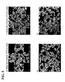
- Figs. 4(a) and 4(b) are SEM micrographs of the sample in Example 7 taken at ⁇ 150 and ⁇ 300, respectively.
- Figs. 4(c) and 4(d) are SEM micrographs of the sample in Example 9 taken at ⁇ 150 and ⁇ 300, respectively.
- the sample in Example 7 has an alumina mixing ratio of 1% by weight, and the sample in Example 9 has an alumina mixing ratio of 5% by weight.
- Each of the samples in Examples 7 and 9 has a porosity of about 42%.
- point A represents silicon carbide
- point B represents aluminum
- point C represents a pore. It has been confirmed from Figs.
- neck areas are mainly composed of silicon carbide, and aluminum is present in parts of the neck areas. It has also been confirmed that the amount of aluminum present in the neck areas is small in Example 7 compared with that in Example 9.
- Figs. 5(a) and 5(b) are SEM micrographs of the sample in Example 57 taken at ⁇ 150 and ⁇ 300, respectively.
- Figs. 5(c) and 5(d) are SEM micrographs of the sample in Example 61 taken at x150 and ⁇ 300, respectively.
- the sample in Example 57 has an alumina mixing ratio of 0.5% by weight
- the sample in Example 61 has an alumina mixing ratio of 5% by weight.
- Each of the samples in Examples 57 and 51 has a porosity of about 60%.
- neck areas are mainly composed of silicon carbide, and aluminum is present in parts of the neck areas. It has also been confirmed that the amount of aluminum present in the neck areas is small in Example 57 compared with that in Example 61. It has been assumed that aluminum presents in the neck areas influences the bending strength at high temperature (900°C).
- Example 7 the amount of alumina as a sintering aid added was 1% by weight (0.53% by weight in terms of aluminum metal) while the amount of alumina contained in the fired honeycomb filter 10 was 0.89% by weight (0.47% by weight in terms of aluminum metal).
- Example 8 the amount of alumina added was 3% by weight (1.59% by weight in terms of aluminum metal) while the amount of alumina contained in the fired honeycomb filter 10 was 2.44% by weight (1.29% by weight in terms of aluminum metal).
- Example 9 the amount of alumina added was 5% by weight (2.65% by weight in terms of aluminum metal) while the amount of alumina contained in the fired honeycomb filter 10 was 2.44% by weight (2.07% by weight in terms of aluminum metal).
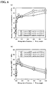
- Fig. 6(a) is a graph showing the relationship between the alumina mixing ratio and the bending strength at room temperature in Examples 1 to 27, and Fig. 6(b) is a graph showing the relationship between the alumina mixing ratio and the bending strength at 900°C in Examples 1 to 27.
- Fig. 7(a) is a graph showing the relationship between the alumina mixing ratio and the bending strength at room temperature in Examples 28 to 54, and Fig. 7(b) is a graph showing the relationship between the alumina mixing ratio and the bending strength at 900° C in Examples 28 to 54.
- Fig. 8 is a graph showing the relationship between the alumina mixing ratio and the ratio of high-temperature bending strength in Examples 1 to 27.
- Fig. 9 is a graph showing the relationship between the alumina mixing ratio and the ratio of high-temperature bending strength in Examples 28 to 54.
- Fig. 10 is a graph showing the relationship between the alumina mixing ratio and the ratio of high-temperature bending strength in Examples 55 to 75.
- the ratio of high-temperature bending strength is 55% or more, and a decrease in the high-temperature bending strength is suppressed.
- the ratio of high-temperature bending strength is about 80%, and the decrease in the high-temperature bending strength is further suppressed.
- the porosity is set at about 60%, this trend does not substantially change. It has been found that, in the samples with an alumina mixing ratio of 0.1% to 1.0% by weight shown in Figs.
- both the bending strength at 900° C and the bending strength at room temperature is 25 MPa or more, which is sufficient for practical use.
- an alumina mixing ratio of 0.3% to 0.7% by weight is in accordance with the present invention.
- the sintering temperature can be decreased and a decrease in the ratio of the strength at high temperature to the strength at room temperature can be suppressed.
- the bending strength at 900°C is 55% or more (in particular 80% or more) relative to the bending strength at room temperature, and thus it has been confirmed that the decrease in the ratio of the strength at high temperature to the strength at room temperature is suppressed.
- the present invention can be applied, for example, to the case where by allowing a fluid to flow through a porous body, unwanted substances contained in the fluid are removed or a component contained in the fluid is converted to another component.
- the present invention can be used in the industry related to various kinds of filters for purifying gases and liquids.
Description
- The present invention relates to a method for producing a porous body, a porous body, and a honeycomb structure.
- As the method for producing a dense sintered silicon carbide ceramic body, a method has been known in which alumina, which is a sintering aid, in an amount in the range of 2% to 25% by weight, is mixed to silicon carbide, molding is performed at a pressing pressure of 2,000 kg/cm2, and hot-press sintering is performed in an argon gas atmosphere at a firing temperature of 1,900° C under a pressure of 200 kg/cm2. For example, in the method described in
JP-A 60-239360 JP-A 63-190758 EP 1808228 A1 discloses a honeycomb structure and a method for producing it, which involves molding a puddle contouring coarse grained and fine-grained silicon carbide and alumina. - As described above, in the dense sintered silicon carbide ceramic body, when the amount of alumina mixed exceeds a predetermined range, the ratio of the strength at high temperature to the strength at room temperature tends to decrease; and when the amount of alumina mixed is within a predetermined range, the strength at high temperature tends to be higher than the strength at room temperature. However, in the method for producing a porous body, such a tendency is not observed. A method has not been known for producing a porous body in which the firing temperature can be decreased and a decrease in the ratio of the strength at high temperature to the strength at room temperature can be suppressed.
- The present invention has been achieved in view of the above-mentioned problems. It is an object of the invention to provide a method for producing a porous body in which the firing temperature can be decreased and a decrease in the ratio of the strength at high temperature to the strength at room temperature can be suppressed. It is another object of the invention to provide a porous body in which a decrease in the ratio of the strength at high temperature to the strength at room temperature is suppressed, and a honeycomb structure including the same.
- The present inventors have studied by applying the amount of a sintering aid added in a method for producing a dense body to a method for producing a porous body. As a result, it has been found that in the porous body, unlike the dense body, even if the amount of the sintering aid is decreased, the relationship between the bending strength at high temperature and the bending strength at room temperature is not reversed, and in the method for producing the porous body, a different result is obtained from that in the method for producing the dense body. As a result of intensive research, with respect to a porous body, the present inventors have found a range of the amount of a sintering aid added in which a decrease in the ratio of the strength at high temperature to the strength at room temperature can be suppressed, and thus the present invention has been achieved.
- The present invention provides a method for producing a porous body according to claim 1.
- In the method for producing the porous body, ceramic particles and a sintering aid that accelerates sintering of ceramic particles are mixed to form a puddle, the puddle is molded into a molded body, and the molded body is fired. At this time, since sintering of ceramic particles is accelerated by the sintering aid, it is possible to perform firing at low temperature compared with the case where ceramic particles are sintered without using a sintering aid.
- In the method for producing the porous body of the invention, in the starting material mixing step, mixing is performed such that the amount of the sintering aid is 0.3% to 0.7% by weight relative to the total amount of the ceramic particles and the sintering aid. When the amount of the sintering aid exceeds 0.7% by weight, in some cases, the decrease in the strength at high temperature cannot be suppressed sufficiently.
- In the method for producing the porous body of the invention, alumina, which is an oxide of Al, is the sintering aid. The reason for this is that alumina can accelerate sintering of ceramic particles.
- In the method for producing the porous body of the invention, the ceramic particles are silicon carbide particles. Since silicon carbide has high thermal conductivity and is often used for porous bodies, use of silicon carbide is significant to the present invention. The firing temperature is in the range of 1,900°C to 2,100°C. Silicon carbide is not easily sintered, and it is usually necessary to perform firing at high temperature (e.g., 2,200°C) to cause sintering. However, in the production method of the present invention, since the sintering aid is mixed, even at a firing temperature in the range of 1,900°C to 2,100°C, satisfactory strength can be obtained.
- In the method for producing the porous body of the invention, in the molding and firing step, extrusion molding is performed at a pressure of 20 MPa or less. In such a manner, since ceramic particles are not easily densified, a porous material can be obtained relatively easily.
- The present invention also provides a porous body according to
claim 2. - The bending strength of the body at 900° C is 55% or more relative to the bending strength at room temperature. Preferably, the strength at 900°C is 80% or more relative to the strength at room temperature.
- In the porous body of the invention, both the bending strength at 900° C and the bending strength at room temperature are preferably 25 MPa or more. The reason for this is that when both the bending strength at 900°C and the bending strength at room temperature are 25 MPa or more, the porous body has strength sufficient for practical use.
- In the porous body of the invention, the ceramic particles are silicon carbide particles. Since silicon carbide has high thermal conductivity and is often used for porous bodies, use of silicon carbide is significant to the present invention.
- A honeycomb structure of the invention according to claim 5 includes the porous body according to any of the various embodiments described above. In the porous body of the present invention, a decrease in the ratio of the strength at high temperature to the strength at room temperature can be suppressed. Consequently, the same effect can be achieved in the honeycomb structure composed of the porous body.
-
-
Fig. 1(a) is a schematic perspective view showing ahoneycomb filter 10 according to an embodiment of the present invention, andFig. 1(b) is a sectional view taken along the line X-X ofFig. 1(a) . -
Fig. 2 is a schematic diagram showing ahoneycomb filter 20 according to an embodiment of the present invention. -
Fig. 3 is a schematic diagram showing ahoneycomb filter 30 according to an embodiment of the present invention. -
Fig. 4 shows SEM micrographs in Examples 7 and 9 according to an embodiment of the present invention. -
Fig. 5 shows SEM micrographs in Examples 57 and 61. -
Fig. 6 shows graphs showing the relationships between the alumina mixing ratio and the three-point bending strength in Examples 1 to 27. -
Fig. 7 shows graphs showing the relationships between the alumina mixing ratio and the three-point bending strength in Examples 28 to 54. -
Fig. 8 is a graph showing the relationship between the alumina mixing ratio and the ratio of high-temperature bending strength in Examples 1 to 27. -
Fig. 9 is a graph showing the relationship between the alumina mixing ratio and the ratio of high-temperature bending strength in Examples 28 to 54. -
Fig. 10 is a graph showing the relationship between the alumina mixing ratio and the ratio of high-temperature bending strength in Examples 55 to 75. - Best modes for carrying out the present invention will now be described below with reference to the drawings.
First, ahoneycomb filter 10, which is a honeycomb structure in the shape of a filter according to an embodiment of the present invention, will be described.Fig. 1(a) is a schematic perspective view showing thehoneycomb filter 10 according to an embodiment of the present invention, andFig. 1(b) is a sectional view taken along the line X-X ofFig. 1(a) . Thehoneycomb filter 10 is a ceramic filter that purifies particulate matter contained in exhaust emissions. Thehoneycomb filter 10 has a rectangular pillar shape and has a plurality of through-holes 12 arranged in parallel in the longitudinal direction. In thehoneycomb filter 10, end faces of the through-holes 12 are alternately plugged with pluggingportions 14. Consequently, in thehoneycomb filter 10, exhaust emissions flowing from an inlet of a through-hole 12 pass through apartition wall 15 into the adjacent through-hole 12, and at this time, particulate matter contained in exhaust emissions is captured by thewall 15 of thehoneycomb filter 10. - The
honeycomb filter 10 has a porosity of preferably 35% to 70%, and more preferably 50% to 70%. When the porosity is less than 35%, in some cases, the function of purifying particulate matter may be undesirably insufficient. When the porosity exceeds 70%, the strength may be undesirably decreased. Thehoneycomb filter 10 has outside dimensions of 34.3 mm × 34.3 mm × 150 mm. The thickness of thepartition wall 15 between the adjacent through-holes 12 is set in the range of 0.1 to 10.0 mm (more preferably in the range of 0.2 to 6.0 mm), and the number of through-holes 12 per unit area is set at 0.16 to 62 pieces/cm2 (1.0 to 400 cpsi). In this example, each of the through-holes 12 has a square cross-sectional shape. Each of the through-holes 12 may have, for example, a substantially triangular or substantially hexagonal cross-sectional shape. - The
honeycomb filter 10 contains silicon carbide as ceramic particles serving as an aggregate and elemental Al derived from alumina serving as a sintering aid. The amount of elemental Al contained in thehoneycomb filter 10 is, in terms of alumina, in the range of 0.3% to 0.7% by weight, and in terms of aluminum metal, in the range of 0.15% to 0.35% by weight. Both the bending strength at 900°C and the bending strength at room temperature (e.g., 25° C) of thehoneycomb filter 10 are 25 MPa or more, and the bending strength at 900° C is 55% or more (in particular, 80% or more) relative to the bending strength at room temperature. Furthermore, the neck areas, in which silicon carbide particles contained in thehoneycomb filter 10 are bound together, are primarily composed of silicon carbide, and elemental Al mixed as the sintering aid is present in parts of the neck areas. - Next, each step of a method for producing the
honeycomb filter 10 will be described. The method for producing thehoneycomb filter 10 will be described in which silicon carbide is used as ceramic particles and alumina is used as a sintering aid. As the silicon carbide, a mixture of coarse particles having a predetermined particle size (hereinafter referred to as "coarse-grained silicon carbide") and fine particles composed of the same material as the coarse particles and having an average particle size smaller than the predetermined particle size (hereinafter referred to as "fine-grained silicon carbide") is used. The fine-grained silicon carbide may have a different crystalline form from that of the coarse-grained silicon carbide. The average particle size is determined by a laser diffraction scattering method using a Mastersizer Micro manufactured by MALVERN Instruments Ltd. - Coarse-grained silicon carbide to be used, which is a starting material for the honeycomb filter, has an average particle size in the range of 5 to 100 µm (preferably 20 to 40 µm). Fine-grained silicon carbide to be used has an average particle size in the range of 0.1 to 10 µm (preferably in the range of 0.1 to 5 µm). Alumina to be used has an average particle size in the range of 0.1 to 10 µm (preferably in the range of 0.1 to 5 µm). The fine-grained silicon carbide to be used has a smaller average particle size than that of the coarse-grained silicon carbide. Note that alumina has high stability at high temperatures, functions as a sintering aid effectively, and can accelerate sintering of silicon carbide. With respect to the mixing ratio of the starting materials, preferably, the amount of coarse-grained silicon carbide is 60% to 80% by weight (in particular, 65% to 75% by weight), the amount of fine-grained silicon carbide is 18% to 38% by weight (in particular, 25% to 30% by weight), and the amount of alumina is 0.3% to 0.7% by weight, relative to the total amount of coarse-grained silicon carbide, fine-grained silicon carbide, and alumina. When the amount of coarse-grained silicon carbide is less than 60% by weight, the amounts of fine-grained silicon carbide and alumina increase relatively, and the pore size of the honeycomb filter undesirably decreases. When the amount exceeds 80% by weight, the amounts of fine-grained silicon carbide and alumina decrease relatively, and strength is undesirably decreased. Furthermore, when the amount of fine-grained silicon carbide is less than 18% by weight, the amount of the material that forms the connection areas (neck areas) between particles of coarse-grained silicon carbide decreases, and thermal conductivity and thermal shock resistance undesirably decrease. When the amount exceeds 38% by weight, the pore size of the honeycomb filter undesirably decreases.
- Subsequently, 15 parts by weight or less (more preferably 8 to 12 parts by weight) of a pore-forming agent is mixed to 100 parts by weight of a mixture of the coarse-grained silicon carbide, fine-grained silicon carbide, and alumina described above. When the pore-forming agent is mixed in an amount exceeding 15 parts by weight, the strength of the
honeycomb filter 10 after firing undesirably decreases. Examples of the pore-forming agent include at least one kind of material selected from balloons that are fine hollow spheres containing an oxide-based ceramic as a main component, spherical acrylic particles, graphite, and the like. Examples of the oxide balloons include at least one kind of balloons selected from alumina balloons, glass microballoons, Shirasu balloons, fly ash balloons, mullite balloons, and the like. The amount of the pore-forming agent added (including the case where no addition is made) is appropriately selected depending on the porosity of the desired honeycomb filter. Subsequently, 10 to 30 parts by weight of water is added to 100 parts by weight of a mixture of the coarse-grained silicon carbide, fine-grained silicon carbide, and alumina, followed by mixing to form a puddle. As the dispersion medium, in addition to water, for example, an organic solvent (benzene or the like) or an alcohol (methanol or the like) may be used. Additionally, an organic binder and a molding aid may be appropriately added to the puddle in view of moldability. Examples of the organic binder include at least one organic binder selected from methyl cellulose, carboxymethyl cellulose, hydroxyethyl cellulose, polyethylene glycol, phenolic resins, and epoxy resins. The amount of the organic binder used is preferably 1 to 10 parts by weight relative to 100 parts by weight of the total amount of coarse-grained silicon carbide, fine-grained silicon carbide, and alumina. Examples of the molding aid include ethylene glycol, dextrin, fatty acid soaps, and polyalcohols. The puddle may be mixed, for example, using, a mixer, an attritor, or the like, or may be kneaded thoroughly using a kneader or the like. - The puddle containing coarse-grained silicon carbide, fine-grained silicon carbide, and alumina prepared in the starting material mixing step is molded into a honeycomb shape. As the method for molding the puddle, extrusion, slip casting, pressing, or the like may be used. Herein, molding is performed by extrusion at a molding pressure of 20 MPa or less (more preferably 3 to 12 MPa). The shape of the honeycomb filter to be formed may be selected appropriately, depending on the intended use or the like. Any shape or size may be selected, and for example, the shape may be cylindrical, rectangular pillar, or cylindroid. Herein, a rectangular pillar honeycomb shape in which a plurality of through-holes are arranged in parallel in the longitudinal direction is formed. The size of the through-
holes 12, the number of through-holes 12, and the thickness of a partition wall between the adjacent through-holes 12 may be selected appropriately, depending on the purpose of intended use. The sectional shape of each of the through-holes may be rectangular, triangular, or hexagonal. Since fine-grained silicon carbide and alumina are mixed in the puddle, molding is performed in a state in which the fine-grained silicon carbide and alumina are included between particles of coarse-grained silicon carbide. The resulting raw molded body is dried, and then only one end face of each of the plurality of through-holes 12 is plugged by a pluggingportion 14 composed of a paste having the same composition as that of the puddle described above. Specifically, with respect to the plurality of through-holes 12, through-holes 12 having a first plugged end face and a second open end face and through-holes 12 having a first open end face and a second plugged end face are alternately arranged. - Subsequently, the resulting raw molded body is dried and fired. Drying is performed at a temperature of about 100°C to 200°C using a microwave dryer, a hot-air dryer, or the like. When an organic component, such as an organic binder, is added in the starting material mixing step, preferably, calcination is performed before firing to degrease the organic component. The calcination conditions are appropriately selected depending on the amount and kind of the organic component added. For example, the calcination is performed by heating at about 300° C to 650° C in an oxygen atmosphere. Firing of the molded body is carried out under the following conditions: in an inert gas atmosphere, such as nitrogen or argon, at 1,900°C to 2,100° C. Herein, since sintering of silicon carbide is accelerated by the sintering aid, it is possible to decrease the firing temperature as compared with the case where silicon carbide is sintered without using a sintering aid. Thereby, the
honeycomb filter 10 according to this embodiment can be obtained. - The method for producing the rectangular
pillar honeycomb filter 10 is described above. As shown inFig. 2 , using thehoneycomb filter 10 as ahoneycomb unit 11, a plurality ofhoneycomb units 11 may be joined and formed into a cylindrical shape to produce ahoneycomb filter 20. Thehoneycomb filter 20 includes a plurality ofhoneycomb units 11, eachhoneycomb unit 11 having a rectangular pillar shape and having a plurality of through-holes 12 arranged in parallel in the longitudinal direction; a sealingmaterial layer 26 which joins theouter surfaces 13 of thehoneycomb units 11, in which the through-holes 12 are not open; and acoating material layer 27 which covers the outer circumferential surface in which the through-holes 12 are not open. A method for producing thehoneycomb filter 20 will be described below. First, a plurality of honeycomb filters 10 are produced ashoneycomb units 11. A sealing material paste is applied to theouter surface 13 of eachhoneycomb unit 11 and a plurality ofhoneycomb units 11 are joined. The paste is dried and solidified at 120°C to form a sealingmaterial layer 26. The resulting joined product is cut into a cylindrical shape with a diamond cutter or the like. The outer circumferential surface thereof, in which the through-holes 12 are not open, is coated with a paste similar to the sealing material paste. Drying and solidification are performed at 120°C to form acoating material layer 27. Ahoneycomb filter 20 is thereby obtained. Herein, the sealing material paste which can be used contains at least one of inorganic fibers and inorganic particles and appropriately contains an inorganic binder or an organic binder. Examples of the inorganic fibers include at least one kind of ceramic fibers selected from silica-alumina, mullite, alumina, silica, and the like. Examples of the inorganic particles include at least one kind of particles selected from silicon carbide, silicon nitride, boron nitride, and the like. Examples of the inorganic binder include at least one binder selected from silica sol, alumina sol, and the like. Examples of the organic binder include at least one binder selected from polyvinyl alcohol, methyl cellulose, ethyl cellulose, carboxymethyl cellulose, and the like. Furthermore, as shown inFig. 3 , acylindrical honeycomb filter 30 having through-holes 32 may be integrally molded, and by providing pluggingportions 34 in alternate end faces of the though-holes 32 of thehoneycomb filter 30, an integral type DPF may be produced. Furthermore, a honeycomb structure in which the pluggingportions 14 of thehoneycomb filter portions 34 of thehoneycomb filter 30 are not provided may be produced. - The application of the
honeycomb filter 10 has been described as purification of particulate matter contained in exhaust emissions. Thehoneycomb filter 10 may also be used as a catalyst carrier for carrying a catalyst that converts exhaust gas of vehicles. Furthermore, thehoneycomb filter 10 can also be used in the application in which a catalyst is not carried (for example, adsorbents which adsorb gas components, liquid components, and the like). - In the
honeycomb filter 10 produced by the production method described above, the bending strength at 900°C is 55% or more (in particular, 80% or more) relative to the bending strength at room temperature. Although not clear at present, the reason for the fact that the high-temperature bending strength is not decreased is believed to be as follows. That is, in the raw molded body before firing, fine-grained silicon carbide and alumina are included between particles of coarse-grained silicon carbide. When the molded body is fired, neck areas in which particles of coarse-grained silicon carbide are bound to one another are formed. Substances containing aluminum may be fixed around the neck areas, or the neck areas by themselves may be composed of a substance containing aluminum. The reason for the fact that the neck areas are mainly composed of silicon carbide is assumed to be that fine-grained silicon carbide enters between particles of coarse-grained silicon carbide during molding. When the molded body is fired in an inert gas at high temperatures, in some cases, alumina may be reduced to aluminum metal by carbon contained in silicon carbide. Since the melting point of aluminum is low (about 660° C), in the case in which the neck areas are composed of aluminum metal and thehoneycomb filter 10 is used at high temperature (e.g., 900°C), it is believed that the strength is decreased under the influence of the aluminum metal present in the neck areas. In particular, as the amount of elemental Al present increases, the neck areas composed of aluminum metal increase. When the neck areas composed of aluminum metal increase, the high-temperature strength of thehoneycomb filter 10 decreases. The strength is assumed to decrease significantly at a temperature higher than the melting point of an element (e.g., Al) contained in the sintering aid. On the other hand, when the mixing ratio of alumina, which is a sintering aid, is low, the effect of accelerating sintering of silicon carbide cannot be displayed, resulting in a decrease in strength. Consequently, when the mixing ratio of alumina is in a predetermined range (0.3% to 0.7% by weight) relative to the total amount of silicon carbide and alumina, sintering of silicon carbide can be accelerated, and a decrease in the ratio of the strength at high temperature to the strength at room temperature can be suppressed. - According to the embodiments described above in detail, during the production of the
honeycomb filter 10, silicon carbide and alumina are mixed to form a puddle, the puddle is molded into a molded body under a pressure of 20 MPa or less, and the resulting molded body is fired at a firing temperature that is lower than the temperature at which sintering is performed without mixing a sintering aid. At this time, since sintering of ceramic particles is accelerated by a sintering aid, it is possible to perform firing at a low temperature compared with the case where ceramic particles are sintered without using a sintering aid. Furthermore, since the puddle is molded at a pressure of 20 MPa or less, ceramic particles are not easily densified and a porous material can be obtained easily. Consequently, in the production method, it is possible to produce a honeycomb filter 10 (porous body) in which the firing temperature can be decreased and a decrease in the ratio of the strength at high temperature to the strength at room temperature can be suppressed. - Examples will be described below, in which honeycomb filters 10 were specifically produced.
- First, 7,000 parts by weight of α-silicon carbide powder (average particle size: 30 µm) as coarse-grained silicon carbide among ceramic particles, 3,000 parts by weight of α-silicon carbide powder (average particle size: 0.5 µm) as fine-grained silicon carbide among ceramic particles, and 2,970 parts by weight of water were mixed, and 1,050 parts by weight of methyl cellulose as an organic binder, 230 parts by weight of glycerol as a plasticizer, and 500 parts by weight of a lubricant (trade name: UNILUB; manufactured by NOF Corporation) were further added to the mixture, followed by kneading to obtain a puddle. In Example 1, γ-alumina (average particle size: 0.5 µm) as a sintering aid was not mixed. The puddle was extrusion-molded at a molding pressure of 5 MPa with an extruder into a rectangular pillar shape in which a plurality of through-holes were arranged in parallel in the longitudinal direction, and thereby a raw molded body in the shape of
honeycomb filter 10 in which pluggingportions 14 were not formed was obtained. Subsequently, the resulting raw molded body was dried with a microwave dryer. The end faces of a plurality of through-holes arranged in parallel in the longitudinal direction were alternately plugged with pluggingportions 14 composed of a paste having the same composition as that of the puddle described above, followed by drying and degreasing at 400°C for 3 hours. The molded body was fired at ordinary pressure under an argon atmosphere at 2,000° C for 3 hours to form ahoneycomb filter 10 composed of a silicon carbide sintered body having dimensions of 34.3 mm × 34.3 mm × 150 mm, 31 through-holes/cm2 (200 cpsi), and partition walls with a thickness of 0.3 mm. Table 1 summarizes the numerical values, such as the average particle size of coarse-grained silicon carbide which is a starting material, the mixing ratio of silicon carbide relative to the total amount of silicon carbide (coarse-grained silicon carbide and fine-grained silicon carbide) and alumina, the mixing ratio of alumina relative to the total amount of silicon carbide and alumina, and the firing temperature with respect to thehoneycomb filter 10 in Example 1. Note that the mixing ratio of each component is in terms of percent by weight relative to the total amount of coarse-grained silicon carbide, fine-grained silicon carbide, and alumina. Table 1 also shows the summary regarding Examples 2 to 27, which will be described below. In each Example, the mixing ratio between coarse-grained silicon carbide and fine-grained silicon carbide was set at 7:3. Furthermore, Table 1 also shows the measurement results of the pore size, porosity, three-point bending strength at room temperature, three-point bending strength at 900° C, and the ratio of three-point bending strength at 900° C to three-point bending strength at room temperature (which is assumed to be 100) (hereinafter referred to as "ratio of high-temperature bending strength"), which correspond to the evaluation results described below. -
Table 1 Sample SiC1) particle size SiC2) mixing ratio Al2O3 mixing ratio Firing temperature Pore size Porosity Bending strength at room temperature Bending strength at 900 °C Ratio of high-temperature bending strength µm % by weight % by weight °C µm % Mpa Mpa % *Example 1 30 100 0 2000 7.1 42.9 7 6.1 87.14 *Example 2 30 99.95 0.05 2000 7.0 43.6 10 8.1 81.00 *Example 3 30 99.9 0.1 2000 6.9 42.4 31 29.4 94.84 Example 4 30 99.7 0.3 2000 7.1 42.8 39 32.2 82.56 Example 5 30 99.5 0.5 2000 8.9 39.4 42 31.5 75.00 Example 6 30 99.3 0.7 2000 9.0 41.0 42 30.0 71.43 *Example 7 30 99 1 2000 9.1 44.8 43 27.1 63.02 *Example 8 30 97 3 2000 8.9 42.6 45 18.9 42.00 *Example 9 30 95 5 2000 9.0 43.1 50 11.6 23.20 *Example 10 30 100 0 2050 7.2 42.5 11 8.9 80.91 *Example 11 30 99.95 0.05 2050 7.1 42.1 16 13.3 83.13 *Example 12 30 99.9 0.1 2050 7.0 43.6 32 30.2 94.38 Example 13 30 99.7 0.3 2050 7.3 41.8 41 33.9 82.68 Example 14 30 99.5 0.5 2050 9.4 41.6 42 32.8 78.10 Example 15 30 99.3 0.7 2050 9.3 43.9 43 31.1 72.33 *Example 16 30 99 1 2050 9.1 40.2 42 28.3 67.38 *Example 17 30 97 3 2050 9.0 39.7 51 20.4 40.00 *Example 18 30 95 5 2050 9.1 42.0 54 14.7 27.22 *Example 19 30 100 0 2100 7.2 41.8 17 15.0 88.24 *Example 20 30 99.95 0.05 2100 7.2 44.8 19 16.9 88.95 *Example 21 30 99.9 0.1 2100 7.2 43.7 32 29.9 93.44 Example 22 30 99.7 0.3 2100 7.5 39.2 41 38.0 92.68 Example 23 30 99.5 0.5 2100 9.8 40.6 47 40.9 87.02 Example 24 30 99.3 0.7 2100 9.8 41.4 43 35.0 81.40 *Example 25 30 99 1 2100 10.5 44.5 44 30.9 70.23 *Example 26 30 97 3 2100 9.2 42.8 55 23.3 42.36 *Example 27 30 95 5 2100 9.2 43.8 56 18.2 32.50 1) Average particle size of coarse-grained silicon carbide
2) Mixing ratio of silicon carbide (corase-grained silicon carbide plus fine-grained silicon carbide)
*) Examples not in accordance with the present invention - Honeycomb filters 10 in Examples 2 to 9 were produced as in Example 1 except that γ-alumina (average particle size: 0.5 µm) as a sintering aid was mixed to the starting materials at a mixing ratio (0% to 5% by weight) shown in Table 1 and designing was performed as shown in Table 1. Furthermore, honeycomb filters 10 in Examples 10 to 18 were produced as in Example 1 except that the firing temperature was set at 2,050° C and designing was performed so as to satisfy the mixing ratios shown in Table 1. Furthermore, honeycomb filters 10 in Examples 19 to 27 were produced as in Example 1 except that the firing temperature was set at 2,100° C and designing was performed so as to satisfy the mixing ratios shown in Table 1.
- Honeycomb filters 10 in Examples 28 to 36 were produced as in Example 1 except that the average particle size of coarse-grained silicon carbide was set at 22 µm, the firing temperature was set at 2,000° C, and designing was performed so as to satisfy the mixing ratios shown in Table 2. Furthermore, honeycomb filters 10 in Examples 37 to 45 were produced as in Example 1 except that the average particle size of coarse-grained silicon carbide was set at 22 µm, the firing temperature was set at 2,050°C, and designing was performed so as to satisfy the mixing ratios shown in Table 2. Furthermore, honeycomb filters 10 in Examples 46 to 54 were produced as in Example 1 except that the average particle size of coarse-grained silicon carbide was set at 22 µm, the firing temperature was set at 2,100° C, and designing was performed so as to satisfy the mixing ratios shown in Table 2. Table 2 shows the average particle size of coarse-grained silicon carbide which is a starting material, the mixing ratio of the entire silicon carbide, the mixing ratio of alumina, and the firing temperature with respect to the honeycomb filters 10 in Examples 28 to 54, and also summarizes the measurement results of the pore size, porosity, three-point bending strength at room temperature, three-point bending strength at 900°C, and the ratio of high-temperature bending strength, which will be described below.
-
Table 2 Sample SiC1) particle size SiC2) mixing ratio Al2O3 mixing ratio Firing temperature Pore size Porosity Bending strength at room temperature Bending strength at 900 °C Ratio of high-temperature bending strength µm % by weight % by weight °C µm % Mpa Mpa % *Example 28 22 100 0 2000 6.9 43.4 25 22.7 90.80 *Example 29 22 99.95 0.05 2000 6.9 43.3 24 22.1 92.08 *Example 30 22 99.9 0.1 2000 7.0 43.1 29 28.4 97.93 Example 31 22 99.7 0.3 2000 7.3 41.8 41 37.7 91.95 Example 32 22 99.5 0.5 2000 7.4 42.0 50 46.0 92.00 Example 33 22 99.3 0.7 2000 8.0 40.9 46 39.0 84.78 *Example 34 22 99 1 2000 8.6 39.2 45 26.0 57.78 *Example 35 22 97 3 2000 8.7 42.1 43 18.2 42.33 *Example 36 22 95 5 2000 8.9 43.1 48 12.8 26.67 *Example 37 22 100 0 2050 7.0 40.9 31 28.4 91.61 *Example 38 22 99.95 0.05 2050 7.0 41.2 29 26.7 92.07 *Example 39 22 99.9 0.1 2050 7.1 43.3 32 30.1 94.06 Example 40 22 99.7 0.3 2050 7.7 42.2 41 35.9 87.56 Example 41 22 99.5 0.5 2050 8.1 44.7 47 41.4 88.09 Example 42 22 99.3 0.7 2050 8.1 43.6 46 39.8 86.52 *Example 43 22 99 1 2050 8.4 41.6 47 27.8 59.15 *Example 44 22 97 3 2050 8.9 42.6 47 19.0 40.43 *Example 45 22 95 5 2050 9.0 43.7 50 12.1 24.20 *Example 46 22 100 0 2100 7.0 43.3 38 34.4 90.53 *Example 47 22 99.95 0.05 2100 7.1 40.4 38 32.5 85.53 *Example 48 22 99.9 0.1 2100 7.2 40.5 33 29.7 90.00 Example 49 22 99.7 0.3 2100 7.7 42.3 43 40.0 93.02 Example 50 22 99.5 0.5 2100 8.7 44.6 54 45.0 83.33 Example 51 22 99.3 0.7 2100 8.9 43.6 54 43.6 80.74 *Example 52 22 99 1 2100 8.8 42.5 53 32.2 60.75 *Example 53 22 97 3 2100 9.0 40.8 52 21.5 41.35 *Example 54 22 95 2100 9.2 40.6 55 15.5 28.18 1) Average particle size of coarse-grained silicon carbide
2) Mixing ratio of silicon carbide (corase-grained silicon carbide plus fine-grained silicon carbide)
*) Examples not in accordance with the present invention - First, 6,993 parts by weight of coarse-grained silicon carbide (average particle size: 30 µm), 2,997 parts by weight of fine-grained silicon carbide (average particle size: 0.5 µm), 10 parts by weight of γ-alumina (average particle size: 0.5 µm) as a sintering aid, and 2,970 parts by weight of water were mixed, and 980 parts by weight of an acrylic resin as a pore-forming agent, 1,050 parts by weight of methyl cellulose as an organic binder, 230 parts by weight of glycerol as a plasticizer, and 500 parts by weight of a lubricant (trade name: UNILUB; manufactured by NOF Corporation) were further added to the mixture, followed by kneading to obtain a puddle. The puddle was subjected to molding and firing as in Example 1 to obtain a
honeycomb filter 10 composed of a silicon carbide sintered body having dimensions of 34.3 mm × 34.3 mm × 150 mm, 31 through-holes/cm2 (200 cpsi), and partition walls with a thickness of 0.3 mm. Table 3 summarizes the numerical values, such as the average particle size of coarse-grained silicon carbide which is a starting material, the mixing ratio of silicon carbide, the mixing ratio of alumina, the mixing ratio of the pore-forming agent, the firing temperature, the pore size, the porosity, and the ratio of high-temperature bending strength with respect to the honeycomb filters 10 in Examples 55 to 75. Note that in the samples shown in Table 1, the average particle size of coarse-grained silicon carbide was set at 30 µm; in the samples shown in Table 2, the average particle size of coarse-grained silicon carbide was set at 22 µm; and in the samples shown in Table 3, the pore-forming agent was added to increase the porosity of the samples shown in Table 1. -
Table 3 Sample SiC1) particle size SiC2) mixing ratio Al2O3 mixing ratio Pore-forming agent mixing ratio3) Firing temperature Pore size Porosity Ratio of high-temperature bending strength µm % by weight % by weight % by weight °C µm % % *Example 55 30 99.9 0.1 9.8 2000 19.2 57.1 92.8 Example 56 30 99.7 0.3 9.8 2000 20.5 58.4 91.1 Example 57 30 99.5 0.5 9.8 2000 22.5 59.1 83.8 Example 58 30 99.3 0.7 9.8 2000 21.8 57.9 75.2 *Example 59 30 99.0 1.0 9.8 2000 21.1 60.2 70.7 *Example 60 30 97.0 3.0 9.8 2000 21.6 57.8 40.2 *Example 61 30 95.0 5.0 9.8 2000 22.5 61.2 22.0 *Example 62 30 99.9 0.1 9.8 2050 18.8 57.3 90.6 Example 63 30 99.7 0.3 9.8 2050 21.7 56.9 82.2 Example 64 30 99.5 0.5 9.8 2050 22.0 59.1 80.0 Example 65 30 99.3 0.7 9.8 2050 20.6 57.4 78.9 *Example 66 30 99.0 1.0 9.8 2050 22.2 60.3 73.0 *Example 67 30 97.0 3.0 9.8 2050 22.4 57.4 39.6 *Example 68 30 95.0 5.0 9.8 2050 21.1 59.9 27.7 *Example 69 30 99.9 0.1 9.8 2100 21.4 58.0 93.3 Example 70 30 99.7 0.3 9.8 2100 20.1 60.9 93.2 Example 71 30 99.5 0.5 9.8 2100 20.7 60.4 90.2 Example 72 30 99.3 0.7 9.8 2100 22.7 55.8 83.3 *Example 73 30 99.0 1.0 9.8 2100 22.4 59.3 71.6 *Example 74 30 97.0 3.0 9.8 2100 20.5 56.5 41.7 *Example 75 30 95.0 5.0 9.8 2100 22.8 60.4 28.0 1) Average particle size of coarse-grained silicon carbide
2) Mixing ratio of silicon carbide (corase-grained silicon carbide plus fine-grained silicon carbide)
3) Pore-forming agent mixing ratio to total of silicon carbide and alumina as 100
*) Examples not in according with the present invention - Honeycomb filters 10 in Examples 56 to 61 were produced as in Example 55 except that γ-alumina (average particle size: 0.5 µm) as a sintering aid was mixed to the starting materials so as to satisfy the mixing ratio (0.1% to 5% by weight) shown in Table 3 and designing was performed as shown in Table 3. Furthermore, honeycomb filters 10 in Examples 62 to 68 were produced as in Example 55 except that the firing temperature was set at 2,050° C and designing was performed so as to satisfy the mixing ratios shown in Table 3. Furthermore, honeycomb filters 10 in Examples 69 to 75 were produced as in Example 55 except that the firing temperature was set at 2,100° C and designing was performed so as to satisfy the mixing ratios shown in Table 3.
- With respect to Examples 7, 9, 57 , and 61, SEM observation was performed. SEM was carried out using a S-4300 manufactured by Hitachi, Ltd. Herein, a cross section obtained by slicing each
honeycomb filter 10 was observed without sputter-coating. - With respect to Examples 1 to 75, three-point bending strength was measured. The measurement was carried out at room temperature (25°C) and at 900°C according to JIS-R1601 using an Instron 5582 as a measuring apparatus. Specifically, using equivalent samples to the sintered bodies in Examples 1 to 75, the samples being obtained by extrusion-molding into a plate shape with dimensions of 4 mm × 3 mm × 40 mm so as to satisfy the mixing ratios, the pore size, and the porosity shown in Tables 1 to 3, followed by firing and processing, at a crosshead speed of 0.5 mm/min and with a span of 30 mm, breaking load was measured by applying a load in a perpendicular direction to calculate the strength. Each sample was measured at room temperature (25° C) and at 900° C. Measurement at 900° C was carried out by setting a firing furnace at 900° C and placing the sample in the firing furnace.
- With respect to Examples 1 to 75, the average pore size and porosity were measured. The measurement was carried out by a mercury press-in method according to JIS-R1655 using an automated porosimeter AutoPore III 9405 manufactured by Shimadzu Corporation as a measuring apparatus. Specifically, each
honeycomb filter 10 was cut into a cube with edges of about 0.8 cm, and the cube was subjected to supersonic cleaning with ion-exchanged water, followed by drying. Then, measurement was carried out using the measuring apparatus described above in a measurement range of 0.2 to 500 µm. The measurement was carried out every 0.1 psia (689 Pa) in a range of 100 to 500 µm, and every 0.25 psia (1720 Pa) in a range of 0.2 to 100 µm. - With respect to Examples 7 to 9, elemental analysis measurement was carried out. The purpose of the measurement is to determine and confirm the amount of the aluminum component contained in the fired
honeycomb filter 10. The elemental analysis measurement was carried out with respect to aluminum by ICP atomic emission spectrometry method according to JIS-R1616 and JIS-K0116 using a Perkin-Elmer Optima 3300DV as a measuring apparatus. The sample to be measured was prepared by a method in which each sample was placed in a pressure decomposition container, thermal decomposition was performed using hydrofluoric acid, nitric acid, and sulfuric acid, silicon was evaporated, and then a hydrochloric acid solution was prepared for measurement. The sample preparation method described above is mainly used for measuring the aluminum component present in the grain boundaries of silicon carbide. -
Figs. 4(a) and 4(b) are SEM micrographs of the sample in Example 7 taken at ×150 and ×300, respectively.Figs. 4(c) and 4(d) are SEM micrographs of the sample in Example 9 taken at ×150 and ×300, respectively. The sample in Example 7 has an alumina mixing ratio of 1% by weight, and the sample in Example 9 has an alumina mixing ratio of 5% by weight. Each of the samples in Examples 7 and 9 has a porosity of about 42%. InFig. 4 , point A represents silicon carbide, point B represents aluminum, and point C represents a pore. It has been confirmed fromFigs. 4(b) and 4(d) , in each of the samples, neck areas are mainly composed of silicon carbide, and aluminum is present in parts of the neck areas. It has also been confirmed that the amount of aluminum present in the neck areas is small in Example 7 compared with that in Example 9. -
Figs. 5(a) and 5(b) are SEM micrographs of the sample in Example 57 taken at ×150 and ×300, respectively.Figs. 5(c) and 5(d) are SEM micrographs of the sample in Example 61 taken at x150 and ×300, respectively. The sample in Example 57 has an alumina mixing ratio of 0.5% by weight, and the sample in Example 61 has an alumina mixing ratio of 5% by weight. Each of the samples in Examples 57 and 51 has a porosity of about 60%. As inFig. 4 , it has been confirmed fromFigs. 5(b) and 5(d) , in each of the samples, neck areas are mainly composed of silicon carbide, and aluminum is present in parts of the neck areas. It has also been confirmed that the amount of aluminum present in the neck areas is small in Example 57 compared with that in Example 61. It has been assumed that aluminum presents in the neck areas influences the bending strength at high temperature (900°C). - With respect to the results of elemental analysis in Examples 7 to 9, in Example 7, the amount of alumina as a sintering aid added was 1% by weight (0.53% by weight in terms of aluminum metal) while the amount of alumina contained in the fired
honeycomb filter 10 was 0.89% by weight (0.47% by weight in terms of aluminum metal). In Example 8, the amount of alumina added was 3% by weight (1.59% by weight in terms of aluminum metal) while the amount of alumina contained in the firedhoneycomb filter 10 was 2.44% by weight (1.29% by weight in terms of aluminum metal). In Example 9, the amount of alumina added was 5% by weight (2.65% by weight in terms of aluminum metal) while the amount of alumina contained in the firedhoneycomb filter 10 was 2.44% by weight (2.07% by weight in terms of aluminum metal). - Data in Examples 1 to 75 shown in Tables 1 to 3 will now be explained with reference to the graphs.
Fig. 6(a) is a graph showing the relationship between the alumina mixing ratio and the bending strength at room temperature in Examples 1 to 27, andFig. 6(b) is a graph showing the relationship between the alumina mixing ratio and the bending strength at 900°C in Examples 1 to 27.Fig. 7(a) is a graph showing the relationship between the alumina mixing ratio and the bending strength at room temperature in Examples 28 to 54, andFig. 7(b) is a graph showing the relationship between the alumina mixing ratio and the bending strength at 900° C in Examples 28 to 54.Fig. 8 is a graph showing the relationship between the alumina mixing ratio and the ratio of high-temperature bending strength in Examples 1 to 27.Fig. 9 is a graph showing the relationship between the alumina mixing ratio and the ratio of high-temperature bending strength in Examples 28 to 54.Fig. 10 is a graph showing the relationship between the alumina mixing ratio and the ratio of high-temperature bending strength in Examples 55 to 75. - As is evident from Tables 1 to 3 and
Figs. 6 and7 , in all the samples, the samples in which alumina was mixed has improved three-point bending strength compared with the samples in which alumina was not mixed, and sintering of silicon carbide is accelerated by alumina. As the alumina mixing ratio increases, the bending strength tends to improve. In particular, at an alumina mixing ratio of 0.1% by weight or more, improvement in bending strength is significant. Although the difference is not significant, coarse-grained silicon carbide having an average particle size of 22 µm exhibits slightly higher bending strength than coarse-grained silicon carbide having an average particle size of 30µm. On the other hand, as is evident fromFigs. 8 to 10 , at an alumina mixing ratio of 1.0% by weight or less, the ratio of high-temperature bending strength is 55% or more, and a decrease in the high-temperature bending strength is suppressed. In particular, in the samples with an alumina mixing ratio of 0.7% by weight or less, the ratio of high-temperature bending strength is about 80%, and the decrease in the high-temperature bending strength is further suppressed. As shown inFig. 10 , even if the porosity is set at about 60%, this trend does not substantially change. It has been found that, in the samples with an alumina mixing ratio of 0.1% to 1.0% by weight shown inFigs. 6 and7 (Examples 3 to 7, Examples 12 to 16, Examples 21 to 25, Examples 30 to 34, Examples 39 to 43, and Examples 48 to 52), both the bending strength at 900° C and the bending strength at room temperature is 25 MPa or more, which is sufficient for practical use. As is evident from these results, in the production of a porous body, an alumina mixing ratio of 0.3% to 0.7% by weight is in accordance with the present invention. Consequently, it has been confirmed that, according to a method for producing a porous body in which silicon carbide as ceramic particles and alumina as a sintering aid are mixed such that the alumina mixing ratio is 0.2% to 0.7% by weight, and molding is performed at a pressure of 20 MPa or less, followed by firing, the sintering temperature can be decreased and a decrease in the ratio of the strength at high temperature to the strength at room temperature can be suppressed. Furthermore, in the honeycomb filters 10 produced by this production method, the bending strength at 900°C is 55% or more (in particular 80% or more) relative to the bending strength at room temperature, and thus it has been confirmed that the decrease in the ratio of the strength at high temperature to the strength at room temperature is suppressed. - The present invention can be applied, for example, to the case where by allowing a fluid to flow through a porous body, unwanted substances contained in the fluid are removed or a component contained in the fluid is converted to another component. Specifically, the present invention can be used in the industry related to various kinds of filters for purifying gases and liquids.
Claims (5)
- A method for producing a porous body comprising:a starting material mixing step of mixing coarse grain silicon carbide and fine grain silicon conside as ceramic particles serving as an aggregate and alumina as a sintering aid such that the amount of the sintering aid is from 0.3 to 0.7% by weight relative to the total amount of the ceramic particles and the sintering aid to form a puddle; anda molding and firing step of molding the puddle into a molded body and firing the molded body at a temperature of from 1900 to 2100°C under an inert gas atmosphere, wherein, in the molding and firing step, extrusion molding is performed at a pressure of 20 MPa or less.
- A porous body comprising:ceramic particles as defined in claim 1 serving as an aggregate; anda sintering aid as defined in claim 1,wherein the bending strength at 900° C is 55% or more relative to the bending strength at room temperature, said porous body being obtainable by the method of claim 1.
- The porous body according to claim 2, wherein the bending strength at 900°C is 80% or more relative to the bending strength at room temperature.
- The porous body according to claim 2 or 3, wherein both the bending strength at 900°C and the bending strength at room temperature are 25 MPa or more.
- A honeycomb structure comprising the porous body according to any one of claims 2 to 4.
Applications Claiming Priority (2)
| Application Number | Priority Date | Filing Date | Title |
|---|---|---|---|
| JP2004287908 | 2004-09-30 | ||
| PCT/JP2005/017367 WO2006035645A1 (en) | 2004-09-30 | 2005-09-21 | Method for manufacturing porous article, porous article and honeycomb structure |
Publications (3)
| Publication Number | Publication Date |
|---|---|
| EP1787968A1 EP1787968A1 (en) | 2007-05-23 |
| EP1787968A4 EP1787968A4 (en) | 2009-07-01 |
| EP1787968B1 true EP1787968B1 (en) | 2012-12-12 |
Family
ID=36118794
Family Applications (1)
| Application Number | Title | Priority Date | Filing Date |
|---|---|---|---|
| EP20050785476 Active EP1787968B1 (en) | 2004-09-30 | 2005-09-21 | Method for manufacturing porous article, porous article and honeycomb structure |
Country Status (4)
| Country | Link |
|---|---|
| US (1) | US7815994B2 (en) |
| EP (1) | EP1787968B1 (en) |
| JP (1) | JP5095215B2 (en) |
| WO (1) | WO2006035645A1 (en) |
Families Citing this family (12)
| Publication number | Priority date | Publication date | Assignee | Title |
|---|---|---|---|---|
| WO2006001509A1 (en) * | 2004-06-25 | 2006-01-05 | Ibiden Co., Ltd. | Process for producing porous body, porous body, and honeycomb structural body |
| EP1808228A4 (en) * | 2004-09-02 | 2008-02-13 | Ibiden Co Ltd | Honeycomb structure, method for production thereof and exhaust gas purification device |
| DE602005015610D1 (en) | 2004-10-12 | 2009-09-03 | Ibiden Co Ltd | CERAMIC WAVE STRUCTURE |
| JP4863904B2 (en) * | 2006-03-31 | 2012-01-25 | イビデン株式会社 | Honeycomb structure and manufacturing method thereof |
| DE602006014830D1 (en) * | 2006-09-14 | 2010-07-22 | Ibiden Co Ltd | Method for producing a honeycomb body and composition for sintered honeycomb bodies |
| JP5328174B2 (en) * | 2008-02-20 | 2013-10-30 | 日本碍子株式会社 | Plugged honeycomb structure |
| JP5377558B2 (en) * | 2011-03-30 | 2013-12-25 | 日本碍子株式会社 | Method for cutting honeycomb dried body and honeycomb dried body cutting apparatus |
| JP5926593B2 (en) * | 2012-03-28 | 2016-05-25 | 日本碍子株式会社 | Porous material, method for producing the same, and honeycomb structure |
| CN104364222B (en) * | 2012-06-15 | 2016-09-14 | 株式会社则武 | Aluminum oxide porous plastid and manufacture method thereof |
| KR101974932B1 (en) * | 2017-05-29 | 2019-05-03 | 한국과학기술연구원 | A compostion for preparing a liquid phase sintered silicon carbide porous body, the liquid phase sintered silicon carbide porous body using the composition having high strength and resistivity and a method for manufacturing thereof |
| JP7038585B2 (en) * | 2018-03-30 | 2022-03-18 | 日本碍子株式会社 | Ceramic porous body and dust collection filter |
| CN109627007A (en) * | 2018-12-28 | 2019-04-16 | 凯龙蓝烽新材料科技有限公司 | Filtering body and preparation method thereof for diesel emission particulate trapping |
Family Cites Families (26)
| Publication number | Priority date | Publication date | Assignee | Title |
|---|---|---|---|---|
| US2171290A (en) * | 1937-01-14 | 1939-08-29 | Battelle Memorial Institute | Method of making clay products |
| JPS60239360A (en) * | 1985-01-21 | 1985-11-28 | 旭硝子株式会社 | Silicon carbide ceramic sintered body |
| EP0240177B1 (en) * | 1986-03-17 | 1993-06-09 | Sumitomo Electric Industries Limited | Ceramic compact, in particular based on silicon nitride and ceramic fibres and process for its production |
| JPS63190758A (en) | 1987-01-30 | 1988-08-08 | 新日本製鐵株式会社 | Silicon carbide-base ceramic sintered body |
| JPH0735730B2 (en) * | 1987-03-31 | 1995-04-19 | 日本碍子株式会社 | Exhaust gas driven ceramic rotor for pressure wave supercharger and its manufacturing method |
| EP0520520B1 (en) * | 1987-04-10 | 1996-09-11 | Hitachi, Ltd. | Ceramic composite and process for production thereof |
| US4946487A (en) * | 1988-11-14 | 1990-08-07 | Norton Company | High temperature filter |
| JP3596910B2 (en) * | 1993-06-14 | 2004-12-02 | 新原 ▲晧▼一 | Porous ceramic body and method for producing the same |
| TW377313B (en) * | 1995-02-27 | 1999-12-21 | Corning Inc | The method of making extruded structures |
| JPH08323842A (en) * | 1995-06-02 | 1996-12-10 | Tsutsunaka Plast Ind Co Ltd | Sheet blow molding and molding thereof |
| US5942454A (en) * | 1996-08-27 | 1999-08-24 | Asahi Glass Company Ltd. | Highly corrosion-resistant silicon carbide product |
| US6287523B1 (en) * | 1997-08-20 | 2001-09-11 | Calsonic Kansei Corporation | Metal thin film for metal catalyst carrier and metal catalyst converter employing the metal thin film |
| JP2002530175A (en) * | 1998-11-20 | 2002-09-17 | コーニンクレッカ フィリップス エレクトロニクス エヌ ヴィ | Catalyst-carrying filter |
| AU7616300A (en) * | 1999-10-05 | 2001-05-10 | Corning Incorporated | Refractory nzp-type structures and method of making and using same |
| JP2001151579A (en) * | 1999-11-26 | 2001-06-05 | Ngk Insulators Ltd | Silicon carbide porous body and method of producing the same |
| JP4136319B2 (en) * | 2000-04-14 | 2008-08-20 | 日本碍子株式会社 | Honeycomb structure and manufacturing method thereof |
| JP4464568B2 (en) * | 2001-02-02 | 2010-05-19 | 日本碍子株式会社 | Honeycomb structure and manufacturing method thereof |
| JP3830382B2 (en) * | 2001-03-14 | 2006-10-04 | 日本碍子株式会社 | Ceramic sintered body and method for producing the same |
| JP4473463B2 (en) * | 2001-03-26 | 2010-06-02 | 日本碍子株式会社 | Porous silicon nitride and method for producing the same |
| WO2002081054A1 (en) * | 2001-04-09 | 2002-10-17 | Corning Incorporated | Porous filter body and method |
| JP4622175B2 (en) * | 2001-07-04 | 2011-02-02 | 株式会社デンソー | Method for gripping dried honeycomb structure |
| DE60316609T2 (en) * | 2002-03-15 | 2008-07-17 | Ibiden Co., Ltd., Ogaki | Ceramic filter for emission control |
| US7259120B2 (en) * | 2004-04-21 | 2007-08-21 | Corning Incorporated | Aluminum titanate ceramic articles and methods of making same |
| WO2006001509A1 (en) | 2004-06-25 | 2006-01-05 | Ibiden Co., Ltd. | Process for producing porous body, porous body, and honeycomb structural body |
| EP1759754B1 (en) * | 2004-06-25 | 2012-12-19 | Ibiden Co., Ltd. | Method for producing a filter for exhaust purification system |
| EP1808228A4 (en) * | 2004-09-02 | 2008-02-13 | Ibiden Co Ltd | Honeycomb structure, method for production thereof and exhaust gas purification device |
-
2005
- 2005-09-21 WO PCT/JP2005/017367 patent/WO2006035645A1/en active Application Filing
- 2005-09-21 EP EP20050785476 patent/EP1787968B1/en active Active
- 2005-09-21 JP JP2006537691A patent/JP5095215B2/en active Active
-
2007
- 2007-03-30 US US11/730,381 patent/US7815994B2/en not_active Expired - Fee Related
Also Published As
| Publication number | Publication date |
|---|---|
| EP1787968A4 (en) | 2009-07-01 |
| JPWO2006035645A1 (en) | 2008-05-15 |
| WO2006035645A1 (en) | 2006-04-06 |
| US7815994B2 (en) | 2010-10-19 |
| JP5095215B2 (en) | 2012-12-12 |
| US20070172632A1 (en) | 2007-07-26 |
| EP1787968A1 (en) | 2007-05-23 |
Similar Documents
| Publication | Publication Date | Title |
|---|---|---|
| EP1787968B1 (en) | Method for manufacturing porous article, porous article and honeycomb structure | |
| EP1452512B1 (en) | Method for producing porous ceramic article | |
| EP1795262B1 (en) | Honeycomb structure | |
| EP1707545B1 (en) | Honeycomb structure and process for producing the same | |
| EP1759754B1 (en) | Method for producing a filter for exhaust purification system | |
| EP1493724B1 (en) | Porous material and method for production thereof | |
| EP1652831A1 (en) | Process for producing porous body, porous body, and honeycomb structural body | |
| KR100882767B1 (en) | Honeycomb structure and method for manufacturing the same | |
| EP1808228A1 (en) | Honeycomb structure, method for production thereof and exhaust gas purification device | |
| EP1795261A1 (en) | Honeycomb structure | |
| EP1736642A1 (en) | Honeycomb structure | |
| EP2767527B1 (en) | Method for producing ceramic honeycomb structure, and ceramic honeycomb structure | |
| EP1818098A1 (en) | Honeycomb structure | |
| EP2130600B1 (en) | Honeycomb structure | |
| EP2286912A2 (en) | Catalyst supporting honeycomb and method of manufacturing the same | |
| WO2001079138A1 (en) | Honeycomb structure and method for its manufacture | |
| EP2105590B1 (en) | Honeycomb structural body | |
| EP2105181B1 (en) | Honeycomb structured body | |
| EP2123356A1 (en) | Honeycomb structure | |
| EP2090559A1 (en) | Honeycomb structured body | |
| EP1482016B1 (en) | Sealing material, method for sealing honeycomb structure and sealed honeycomb structure | |
| EP1787702B1 (en) | Honeycomb structured body | |
| EP2329874A1 (en) | Honeycomb filter and exhaust gas purifying apparatus | |
| JP5111139B2 (en) | Method for producing porous silicon carbide sintered body | |
| KR100818570B1 (en) | Honeycomb structure and seal material |
Legal Events
| Date | Code | Title | Description |
|---|---|---|---|
| PUAI | Public reference made under article 153(3) epc to a published international application that has entered the european phase |
Free format text: ORIGINAL CODE: 0009012 |
|
| 17P | Request for examination filed |
Effective date: 20070227 |
|
| AK | Designated contracting states |
Kind code of ref document: A1 Designated state(s): AT BE BG CH CY CZ DE DK EE ES FI FR GB GR HU IE IS IT LI LT LU LV MC NL PL PT RO SE SI SK TR |
|
| DAX | Request for extension of the european patent (deleted) | ||
| A4 | Supplementary search report drawn up and despatched |
Effective date: 20090603 |
|
| RIC1 | Information provided on ipc code assigned before grant |
Ipc: B01D 46/24 20060101ALI20090527BHEP Ipc: C04B 35/565 20060101ALI20090527BHEP Ipc: C04B 38/00 20060101AFI20060922BHEP Ipc: B01D 39/20 20060101ALI20090527BHEP |
|
| 17Q | First examination report despatched |
Effective date: 20090814 |
|
| GRAP | Despatch of communication of intention to grant a patent |
Free format text: ORIGINAL CODE: EPIDOSNIGR1 |
|
| GRAS | Grant fee paid |
Free format text: ORIGINAL CODE: EPIDOSNIGR3 |
|
| GRAA | (expected) grant |
Free format text: ORIGINAL CODE: 0009210 |
|
| AK | Designated contracting states |
Kind code of ref document: B1 Designated state(s): AT BE BG CH CY CZ DE DK EE ES FI FR GB GR HU IE IS IT LI LT LU LV MC NL PL PT RO SE SI SK TR |
|
| REG | Reference to a national code |
Ref country code: GB Ref legal event code: FG4D |
|
| REG | Reference to a national code |
Ref country code: CH Ref legal event code: EP |
|
| REG | Reference to a national code |
Ref country code: AT Ref legal event code: REF Ref document number: 588256 Country of ref document: AT Kind code of ref document: T Effective date: 20121215 |
|
| REG | Reference to a national code |
Ref country code: IE Ref legal event code: FG4D |
|
| REG | Reference to a national code |
Ref country code: DE Ref legal event code: R096 Ref document number: 602005037418 Country of ref document: DE Effective date: 20130207 |
|
| PG25 | Lapsed in a contracting state [announced via postgrant information from national office to epo] |
Ref country code: FI Free format text: LAPSE BECAUSE OF FAILURE TO SUBMIT A TRANSLATION OF THE DESCRIPTION OR TO PAY THE FEE WITHIN THE PRESCRIBED TIME-LIMIT Effective date: 20121212 Ref country code: LT Free format text: LAPSE BECAUSE OF FAILURE TO SUBMIT A TRANSLATION OF THE DESCRIPTION OR TO PAY THE FEE WITHIN THE PRESCRIBED TIME-LIMIT Effective date: 20121212 Ref country code: ES Free format text: LAPSE BECAUSE OF FAILURE TO SUBMIT A TRANSLATION OF THE DESCRIPTION OR TO PAY THE FEE WITHIN THE PRESCRIBED TIME-LIMIT Effective date: 20130323 Ref country code: SE Free format text: LAPSE BECAUSE OF FAILURE TO SUBMIT A TRANSLATION OF THE DESCRIPTION OR TO PAY THE FEE WITHIN THE PRESCRIBED TIME-LIMIT Effective date: 20121212 |
|
| REG | Reference to a national code |
Ref country code: NL Ref legal event code: VDEP Effective date: 20121212 |
|
| REG | Reference to a national code |
Ref country code: AT Ref legal event code: MK05 Ref document number: 588256 Country of ref document: AT Kind code of ref document: T Effective date: 20121212 |
|
| REG | Reference to a national code |
Ref country code: LT Ref legal event code: MG4D |
|
| PG25 | Lapsed in a contracting state [announced via postgrant information from national office to epo] |
Ref country code: LV Free format text: LAPSE BECAUSE OF FAILURE TO SUBMIT A TRANSLATION OF THE DESCRIPTION OR TO PAY THE FEE WITHIN THE PRESCRIBED TIME-LIMIT Effective date: 20121212 Ref country code: SI Free format text: LAPSE BECAUSE OF FAILURE TO SUBMIT A TRANSLATION OF THE DESCRIPTION OR TO PAY THE FEE WITHIN THE PRESCRIBED TIME-LIMIT Effective date: 20121212 Ref country code: GR Free format text: LAPSE BECAUSE OF FAILURE TO SUBMIT A TRANSLATION OF THE DESCRIPTION OR TO PAY THE FEE WITHIN THE PRESCRIBED TIME-LIMIT Effective date: 20130313 |
|
| PG25 | Lapsed in a contracting state [announced via postgrant information from national office to epo] |
Ref country code: IS Free format text: LAPSE BECAUSE OF FAILURE TO SUBMIT A TRANSLATION OF THE DESCRIPTION OR TO PAY THE FEE WITHIN THE PRESCRIBED TIME-LIMIT Effective date: 20130412 Ref country code: BE Free format text: LAPSE BECAUSE OF FAILURE TO SUBMIT A TRANSLATION OF THE DESCRIPTION OR TO PAY THE FEE WITHIN THE PRESCRIBED TIME-LIMIT Effective date: 20121212 Ref country code: EE Free format text: LAPSE BECAUSE OF FAILURE TO SUBMIT A TRANSLATION OF THE DESCRIPTION OR TO PAY THE FEE WITHIN THE PRESCRIBED TIME-LIMIT Effective date: 20121212 Ref country code: BG Free format text: LAPSE BECAUSE OF FAILURE TO SUBMIT A TRANSLATION OF THE DESCRIPTION OR TO PAY THE FEE WITHIN THE PRESCRIBED TIME-LIMIT Effective date: 20130312 Ref country code: CZ Free format text: LAPSE BECAUSE OF FAILURE TO SUBMIT A TRANSLATION OF THE DESCRIPTION OR TO PAY THE FEE WITHIN THE PRESCRIBED TIME-LIMIT Effective date: 20121212 Ref country code: SK Free format text: LAPSE BECAUSE OF FAILURE TO SUBMIT A TRANSLATION OF THE DESCRIPTION OR TO PAY THE FEE WITHIN THE PRESCRIBED TIME-LIMIT Effective date: 20121212 Ref country code: AT Free format text: LAPSE BECAUSE OF FAILURE TO SUBMIT A TRANSLATION OF THE DESCRIPTION OR TO PAY THE FEE WITHIN THE PRESCRIBED TIME-LIMIT Effective date: 20121212 |
|
| PG25 | Lapsed in a contracting state [announced via postgrant information from national office to epo] |
Ref country code: NL Free format text: LAPSE BECAUSE OF FAILURE TO SUBMIT A TRANSLATION OF THE DESCRIPTION OR TO PAY THE FEE WITHIN THE PRESCRIBED TIME-LIMIT Effective date: 20121212 Ref country code: PT Free format text: LAPSE BECAUSE OF FAILURE TO SUBMIT A TRANSLATION OF THE DESCRIPTION OR TO PAY THE FEE WITHIN THE PRESCRIBED TIME-LIMIT Effective date: 20130412 Ref country code: RO Free format text: LAPSE BECAUSE OF FAILURE TO SUBMIT A TRANSLATION OF THE DESCRIPTION OR TO PAY THE FEE WITHIN THE PRESCRIBED TIME-LIMIT Effective date: 20121212 Ref country code: PL Free format text: LAPSE BECAUSE OF FAILURE TO SUBMIT A TRANSLATION OF THE DESCRIPTION OR TO PAY THE FEE WITHIN THE PRESCRIBED TIME-LIMIT Effective date: 20121212 |
|
| PLBE | No opposition filed within time limit |
Free format text: ORIGINAL CODE: 0009261 |
|
| STAA | Information on the status of an ep patent application or granted ep patent |
Free format text: STATUS: NO OPPOSITION FILED WITHIN TIME LIMIT |
|
| PG25 | Lapsed in a contracting state [announced via postgrant information from national office to epo] |
Ref country code: DK Free format text: LAPSE BECAUSE OF FAILURE TO SUBMIT A TRANSLATION OF THE DESCRIPTION OR TO PAY THE FEE WITHIN THE PRESCRIBED TIME-LIMIT Effective date: 20121212 |
|
| 26N | No opposition filed |
Effective date: 20130913 |
|
| PG25 | Lapsed in a contracting state [announced via postgrant information from national office to epo] |
Ref country code: CY Free format text: LAPSE BECAUSE OF FAILURE TO SUBMIT A TRANSLATION OF THE DESCRIPTION OR TO PAY THE FEE WITHIN THE PRESCRIBED TIME-LIMIT Effective date: 20121212 |
|
| PG25 | Lapsed in a contracting state [announced via postgrant information from national office to epo] |
Ref country code: IT Free format text: LAPSE BECAUSE OF FAILURE TO SUBMIT A TRANSLATION OF THE DESCRIPTION OR TO PAY THE FEE WITHIN THE PRESCRIBED TIME-LIMIT Effective date: 20121212 |
|
| REG | Reference to a national code |
Ref country code: DE Ref legal event code: R097 Ref document number: 602005037418 Country of ref document: DE Effective date: 20130913 |
|
| PG25 | Lapsed in a contracting state [announced via postgrant information from national office to epo] |
Ref country code: MC Free format text: LAPSE BECAUSE OF FAILURE TO SUBMIT A TRANSLATION OF THE DESCRIPTION OR TO PAY THE FEE WITHIN THE PRESCRIBED TIME-LIMIT Effective date: 20121212 |
|
| REG | Reference to a national code |
Ref country code: CH Ref legal event code: PL |
|
| REG | Reference to a national code |
Ref country code: IE Ref legal event code: MM4A |
|
| PG25 | Lapsed in a contracting state [announced via postgrant information from national office to epo] |
Ref country code: IE Free format text: LAPSE BECAUSE OF NON-PAYMENT OF DUE FEES Effective date: 20130921 Ref country code: LI Free format text: LAPSE BECAUSE OF NON-PAYMENT OF DUE FEES Effective date: 20130930 Ref country code: CH Free format text: LAPSE BECAUSE OF NON-PAYMENT OF DUE FEES Effective date: 20130930 |
|
| PG25 | Lapsed in a contracting state [announced via postgrant information from national office to epo] |
Ref country code: TR Free format text: LAPSE BECAUSE OF FAILURE TO SUBMIT A TRANSLATION OF THE DESCRIPTION OR TO PAY THE FEE WITHIN THE PRESCRIBED TIME-LIMIT Effective date: 20121212 |
|
| PG25 | Lapsed in a contracting state [announced via postgrant information from national office to epo] |
Ref country code: LU Free format text: LAPSE BECAUSE OF NON-PAYMENT OF DUE FEES Effective date: 20130921 Ref country code: HU Free format text: LAPSE BECAUSE OF FAILURE TO SUBMIT A TRANSLATION OF THE DESCRIPTION OR TO PAY THE FEE WITHIN THE PRESCRIBED TIME-LIMIT; INVALID AB INITIO Effective date: 20050921 |
|
| REG | Reference to a national code |
Ref country code: FR Ref legal event code: PLFP Year of fee payment: 12 |
|
| REG | Reference to a national code |
Ref country code: FR Ref legal event code: PLFP Year of fee payment: 13 |
|
| REG | Reference to a national code |
Ref country code: FR Ref legal event code: PLFP Year of fee payment: 14 |
|
| PGFP | Annual fee paid to national office [announced via postgrant information from national office to epo] |
Ref country code: FR Payment date: 20180813 Year of fee payment: 14 |
|
| PGFP | Annual fee paid to national office [announced via postgrant information from national office to epo] |
Ref country code: GB Payment date: 20180919 Year of fee payment: 14 |
|
| GBPC | Gb: european patent ceased through non-payment of renewal fee |
Effective date: 20190921 |
|
| PG25 | Lapsed in a contracting state [announced via postgrant information from national office to epo] |
Ref country code: FR Free format text: LAPSE BECAUSE OF NON-PAYMENT OF DUE FEES Effective date: 20190930 Ref country code: GB Free format text: LAPSE BECAUSE OF NON-PAYMENT OF DUE FEES Effective date: 20190921 |
|
| PGFP | Annual fee paid to national office [announced via postgrant information from national office to epo] |
Ref country code: DE Payment date: 20230802 Year of fee payment: 19 |