EP1640200B1 - Latch for a top of a vehicle - Google Patents
Latch for a top of a vehicle Download PDFInfo
- Publication number
- EP1640200B1 EP1640200B1 EP20050015181 EP05015181A EP1640200B1 EP 1640200 B1 EP1640200 B1 EP 1640200B1 EP 20050015181 EP20050015181 EP 20050015181 EP 05015181 A EP05015181 A EP 05015181A EP 1640200 B1 EP1640200 B1 EP 1640200B1
- Authority
- EP
- European Patent Office
- Prior art keywords
- gear mechanism
- hook
- convertible top
- worm
- gear
- Prior art date
- Legal status (The legal status is an assumption and is not a legal conclusion. Google has not performed a legal analysis and makes no representation as to the accuracy of the status listed.)
- Expired - Fee Related
Links
Images


Classifications
-
- B—PERFORMING OPERATIONS; TRANSPORTING
- B60—VEHICLES IN GENERAL
- B60J—WINDOWS, WINDSCREENS, NON-FIXED ROOFS, DOORS, OR SIMILAR DEVICES FOR VEHICLES; REMOVABLE EXTERNAL PROTECTIVE COVERINGS SPECIALLY ADAPTED FOR VEHICLES
- B60J7/00—Non-fixed roofs; Roofs with movable panels, e.g. rotary sunroofs
- B60J7/185—Locking arrangements
- B60J7/1851—Locking arrangements for locking the foldable soft- or hard-top to the windshield header
-
- Y—GENERAL TAGGING OF NEW TECHNOLOGICAL DEVELOPMENTS; GENERAL TAGGING OF CROSS-SECTIONAL TECHNOLOGIES SPANNING OVER SEVERAL SECTIONS OF THE IPC; TECHNICAL SUBJECTS COVERED BY FORMER USPC CROSS-REFERENCE ART COLLECTIONS [XRACs] AND DIGESTS
- Y10—TECHNICAL SUBJECTS COVERED BY FORMER USPC
- Y10S—TECHNICAL SUBJECTS COVERED BY FORMER USPC CROSS-REFERENCE ART COLLECTIONS [XRACs] AND DIGESTS
- Y10S292/00—Closure fasteners
- Y10S292/05—Automobile top latches
-
- Y—GENERAL TAGGING OF NEW TECHNOLOGICAL DEVELOPMENTS; GENERAL TAGGING OF CROSS-SECTIONAL TECHNOLOGIES SPANNING OVER SEVERAL SECTIONS OF THE IPC; TECHNICAL SUBJECTS COVERED BY FORMER USPC CROSS-REFERENCE ART COLLECTIONS [XRACs] AND DIGESTS
- Y10—TECHNICAL SUBJECTS COVERED BY FORMER USPC
- Y10T—TECHNICAL SUBJECTS COVERED BY FORMER US CLASSIFICATION
- Y10T292/00—Closure fasteners
- Y10T292/08—Bolts
- Y10T292/1043—Swinging
- Y10T292/1044—Multiple head
- Y10T292/1045—Operating means
- Y10T292/1047—Closure
-
- Y—GENERAL TAGGING OF NEW TECHNOLOGICAL DEVELOPMENTS; GENERAL TAGGING OF CROSS-SECTIONAL TECHNOLOGIES SPANNING OVER SEVERAL SECTIONS OF THE IPC; TECHNICAL SUBJECTS COVERED BY FORMER USPC CROSS-REFERENCE ART COLLECTIONS [XRACs] AND DIGESTS
- Y10—TECHNICAL SUBJECTS COVERED BY FORMER USPC
- Y10T—TECHNICAL SUBJECTS COVERED BY FORMER US CLASSIFICATION
- Y10T292/00—Closure fasteners
- Y10T292/08—Bolts
- Y10T292/1043—Swinging
- Y10T292/1075—Operating means
- Y10T292/1082—Motor
-
- Y—GENERAL TAGGING OF NEW TECHNOLOGICAL DEVELOPMENTS; GENERAL TAGGING OF CROSS-SECTIONAL TECHNOLOGIES SPANNING OVER SEVERAL SECTIONS OF THE IPC; TECHNICAL SUBJECTS COVERED BY FORMER USPC CROSS-REFERENCE ART COLLECTIONS [XRACs] AND DIGESTS
- Y10—TECHNICAL SUBJECTS COVERED BY FORMER USPC
- Y10T—TECHNICAL SUBJECTS COVERED BY FORMER US CLASSIFICATION
- Y10T292/00—Closure fasteners
- Y10T292/306—Gear
- Y10T292/308—Swinging catch
Definitions
- the invention relates to a top closure for a vehicle with a gate-controlled locking hook, which is displaceable via guide means from a closed position to an open position, wherein the closure hook cooperates with at least one hook guide, which is in operative connection with a motor-gear unit.
- a good function having convertible top closure of the type mentioned is from the DE 197 21 229 A1 out.
- a geared motor extending in the vehicle longitudinal direction is arranged on one side of the locking hook and connected via a transverse transmission element with a downstream gear unit, which extends on the opposite side of the locking hook.
- the gear unit is formed by a two-stage spur gear.
- the DE 103 00 881 A1 shows a convertible top closure for a vehicle, with a backdrop-controlled, extending in the vehicle longitudinal direction closure hook which is displaceable via guide means from a closed position to an open position, wherein the closure hook cooperates with at least one hook guide, which extends with a running only on one longitudinal side of the locking hook motor Gear unit is in operative connection.
- the electric motor of the motor-gear unit runs parallel to a longitudinal center plane of the vehicle and there is only provided a two-stage gear unit.
- the object of the invention is to develop a top closure of the aforementioned type so that it has a simplified structure and a more compact design.
- the motor-gear unit extending only on one longitudinal side of the closure hook has a simplified structure, wherein a compact design is achieved by the aligned perpendicular to the longitudinal center plane of the vehicle electric motor and the triply geared gear unit ,
- a compact design is achieved by the aligned perpendicular to the longitudinal center plane of the vehicle electric motor and the triply geared gear unit .
- Through the backdrop-controlled locking hook and the special design of the slide track is also an enlarged Holweg des Top cover achieved in the X direction.
- the arrangement of an emergency operating screw, which sets a ring gear of the planetary gear in normal operation of the top closure a relatively simple manual emergency operation for the top cover is created.
- the combination bevel gear, worm gear and planetary gear can represent a relatively high overall ratio.
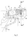
- a convertible top closure 1 serves for securing a convertible top via a movable closure hook 2 to a receptacle 4 arranged on a windscreen frame 3, the convertible top closure 1 having a dimensionally stable front Top frame 5 of the top is connected by screw means which are held in holes 6 of the top closure 1.
- the top closure 1 comprises a fixed to the underside of the front dimensionally rigid top frame 5 base support 7, in its closed position (locking position A) with the windshield frame 3 operatively connected locking hooks 2 and a motor-gear unit 8 for moving the locking hook 2 from the closed position in the Open position (unlocking position B) and vice versa.
- a central, electric motor driven top closure 1 is provided, by means of which the convertible top is pulled in the longitudinal direction of the passenger car against the windshield frame 3 and held in the cocked top position.
- the basic carrier 7 formed, for example, by an aluminum die casting has spaced, extending in the vehicle longitudinal direction and vertically aligned bearing webs 9, 10, 11 for fixing the motor-gear unit 8 and for storage of hook guides 12, 13.
- the closure hook 2 is provided in a front region 14 with a plastic extrusion coating 15, for example made of POM ( Fig. 3 and 4 ).
- a slotted guide 16 is provided for the closure hook 2, wherein a laterally offset clamping pin 17 of the closure hook 2 cooperates with at least one slide track 18 of the base support 7.
- the composite of several juxtaposed web sections slide track 18 is gem. the Fig. 3 and 4 formed by the outer boundary of an arranged on the bearing webs 9, 10 opening 19.
- the entry curves for the front hood section 5 and the front end of the locking hook 2 are in Fig. 4 shown by dashed lines, wherein the inlet curve C the hood section 5 and the inlet curve D are assigned to the locking hook 2.
- the captured between the spaced bearing webs 9, 10 closure hook 2 is pressed by a spring element 20 and a pressure roller 21 from below against the slide track 18.
- the spring element 20 is formed in the embodiment by a double leg spring, which is mounted on a transverse pin of the base support 7. At a transverse overhead end of the double leg spring sits the pressure roller 21, which presses from below against the locking hook 2, whereby the laterally projecting clamping pin 17 is pressed against the slide track 18.
- the rear end of the closure hook 2 cooperates with at least one hook guide 12, 13.
- two differently shaped hook guides 12, 13 are provided for the closure hook 2.
- the motor-gear unit 8 facing away from the hook guide 12 is formed by an elongated drive lever 22 which is connected at its one end via a transverse rivet pin 23 with the rear end of the locking hook 2.
- the other front end of the drive lever 22 is rotatably connected to a hinge pin 24 which is accommodated on the one hand on the central bearing web 10 and on the other hand on the outer bearing web 11.
- the drive lever 22 is placed in the space between the two bearing webs 10, 11.
- the motor gear unit 8 facing hook guide 13 has a disc-shaped contour and is connected via the common rivet pin 23 with the rear end of the locking hook 2 and a polygonal 25 (hexagon) with the transmission output shaft 26 force-transmitting.
- the hook guide 12, 13 is pivoted in the opening and closing operation of the convertible top closure 1 by approximately 160 °, wherein on the base support 7 mechanical stops are formed for both end positions.
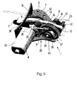
- the motor-gear unit 8 is formed by a prefabricated module 27 which is mounted from one side on an outer bearing web 9 of the base support 7 and secured by a plurality of screws 28 thereto.
- the motor-gear unit 8 comprises a transverse to the longitudinal center plane E-E of the vehicle aligned electric motor 29, which cooperates via a threefold geared transmission unit 30 with a hook guide 12, 13 for the locking hook 2.
- the motor-gear unit 8 seen in the direction of travel is provided on the left side on the base support 7.
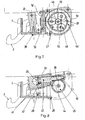
- the electric motor 29 is brought via a rectangular abutment flange 31 to the outside of a multi-part gear housing 32, 33 and fixedly connected by screws 34 ( Fig. 1 ).
- the gear unit 30 is composed of a bevel gear 35, an associated worm gear 36 and a downstream planetary gear 37 together, all gears 35, 36, 37 are housed in the common multi-part gear housing 32, 33.
- the bevel gear 35 comprises a drive bevel gear 39 arranged on an output shaft 38 of the electric motor 29 and a driven bevel gear 41 shrunk on a worm shaft 40, wherein a 90 ° deflection of the force flow takes place by means of the bevel gear set.
- the output shaft 38 of the electric motor 29 extends approximately at right angles to the longitudinal center plane EE of the vehicle and is oriented approximately horizontally, whereas the worm shaft 40 extends parallel and at a distance from the longitudinal center plane EE. Seen in longitudinal section ( Fig. 8 ), the worm shaft 40 slightly increases toward the rear.
- the worm shaft 40 is supported by two rotationally fixed bearings 42, 43 in the gear housing 32, 33.
- an elongated worm 44 is arranged, which drives an underlying worm wheel 45 of the worm gear 36.
- the worm gear transmits the torque to a sun gear 46 of the planetary gear 37, wherein the sun gear 46 is freely rotatably mounted on the transmission output shaft 26.
- the worm wheel 45 is mounted on the sun gear 46 and rotationally connected thereto.
- the cross to the Vehicle longitudinal center plane EE extending transmission output shaft 26 is mounted at its one end in the transmission housing 32, 33. The opposite end of the transmission output shaft 26 is rotatably mounted on the bearing web 9 of the base support 7.
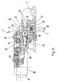
- the planetary gear 37 comprises, in addition to the sun gear 46, a plurality of planetary gears 48 rotatably mounted on a planet carrier 47 and an outer ring gear 49 (FIG. Fig. 7 ).
- the ring gear 49 has an internal toothing 50 and in addition an external toothing 51.
- the ring gear 49 is held, since the external teeth 51 of the ring gear 49 meshes with a standing arranged emergency operating screw 52.
- the emergency operating screw 52 extends in the space between the driven bevel gear 41 and the ring gear 49.
- the emergency operating screw 52 is mounted in the gear housing 32, 33 and has at its lower, the passenger compartment end facing a polygonal socket 53, in the passenger compartment ago a cranked Notbet2011 institutes negotiatel 54th is pluggable.
- the Notbet2011 tos slaughterl 54 is clipped in the embodiment inside a non-illustrated cover of the base support 7, wherein the cover is placed from the passenger compartment forth on the base support 7.
- the inner sun gear 46 drives the outer planet gears 48, wherein the planetary gears 48 additionally mesh with the internal teeth 50 of the fixed ring gear 49.
- the planet gears 48 are each mounted on transverse needle rollers 55 of the planet carrier 47.
- the planet carrier 47 is seated on a polygonal 56 (eg hexagon) of the transmission output shaft 26. Directly next to the polygon for the planet carrier 47 on the transmission output shaft 26 another polygon 25 (eg hex) for the hook guide 13 is arranged.
- the needle rollers 55 of the planet carrier 47 engage in the hook guide 13 and thereby transmit the torque to the hook guide 13. This is coupled via a polygon with the transmission output shaft 26.
- the transmission output shaft 26 rotates as fast as the hook guide 12, 13.
- the hook guide 12, 13 transmits the force on the locking hook 2 due to a lever arm.
- the shutdown of the electric motor 29 and the query whether the convertible top 1 has reached an end position is realized via a switch assembly 57.
- the switch assembly 57 is seated on the gear housing 32, 33.
- Via a cam plate 58 which is fixed on the rotationally fixed end on the transmission output shaft 26, micro switch for indicating the end position in the switch assembly 57 are driven.
Description
Die Erfindung betrifft einen Verdeckverschluss für ein Fahrzeug mit einem kulissengesteuerten Verschlusshaken, der über Führungsmittel aus einer Schließstellung in eine Offenstellung verlagerbar ist, wobei der Verschlusshaken mit zumindest einer Hakenführung zusammenwirkt, die mit einer Motor-Getriebeeinheit in Wirkverbindung steht.The invention relates to a top closure for a vehicle with a gate-controlled locking hook, which is displaceable via guide means from a closed position to an open position, wherein the closure hook cooperates with at least one hook guide, which is in operative connection with a motor-gear unit.
Ein eine gute Funktion aufweisender Verdeckverschluss der eingangs genannten Gattung geht aus der
Die
Aufgabe der Erfindung ist es, einen Verdeckverschluss der eingangs genannten Gattung so weiterzubilden, dass er einen vereinfachten Aufbau und eine kompaktere Bauweise aufweist.The object of the invention is to develop a top closure of the aforementioned type so that it has a simplified structure and a more compact design.
Erfindungsgemäß wird diese Aufgabe durch die Merkmale des Anspruchs 1 gelöst. Weitere die Erfindung in vorteilhafter Weise ausgestaltende Merkmale sind in den Unteransprüchen enthalten.According to the invention, this object is solved by the features of
Die mit der Erfindung hauptsächlich erzielten Vorteile sind darin zu sehen, dass die sich lediglich an einer Längsseite des Verschlusshakens erstreckende Motor-Getriebeeinheit einen vereinfachten Aufbau aufweist, wobei durch den quer zur Längsmittelebene des Fahrzeuges ausgerichteten Elektromotor und die dreifach untersetzte Getriebeeinheit eine kompaktere Bauweise erzielt wird. Durch den kulissengesteuerten Verschlusshaken und die spezielle Ausbildung der Kulissenbahn wird zudem ein vergrößerter Holweg des Verdeckverschlusses in X-Richtung erzielt. Durch die Anordnung einer Notbetätigungsschnecke, die im Normalbetrieb des Verdeckverschlusses ein Hohlrad des Planetengetriebes festsetzt, wird eine relativ einfache manuelle Notbetätigung für den Verdeckverschluss geschaffen. Durch die Kombination Kegelradgetriebe, Schneckengetriebe und Planetengetriebe lässt sich eine relativ hohe Gesamtübersetzung darstellen.The advantages achieved by the invention are to be seen in the fact that the motor-gear unit extending only on one longitudinal side of the closure hook has a simplified structure, wherein a compact design is achieved by the aligned perpendicular to the longitudinal center plane of the vehicle electric motor and the triply geared gear unit , Through the backdrop-controlled locking hook and the special design of the slide track is also an enlarged Holweg des Top cover achieved in the X direction. The arrangement of an emergency operating screw, which sets a ring gear of the planetary gear in normal operation of the top closure, a relatively simple manual emergency operation for the top cover is created. The combination bevel gear, worm gear and planetary gear can represent a relatively high overall ratio.
Ein Ausführungsbeispiel der Erfindung ist in den Zeichnungen dargestellt und wird im Folgenden näher erläutert.
Es zeigt
- Fig. 1
- eine perspektivische Ansicht von schräg vorne auf einen Verdeckverschluss für ein Fahrzeug,
- Fig. 2
- eine Draufsicht auf den Verdeckverschluss,
- Fig. 3
- einen Schnitt nach der Linie III-III der
Fig. 2 , wobei der Verschlusshaken eine verriegelte Stellung einnimmt, - Fig. 4
- einen Schnitt ähnlich
Fig. 3 mit dem Verschlusshaken in entriegelter Stellung, - Fig. 5
- eine Ansicht von der Seite auf den Verdeckverschluss, wobei ein Notbetätigungsschlüssel strichpunktiert dargestellt ist,
- Fig. 6
- eine perspektivische Ansicht von schräg hinten auf den Verdeckverschluss, wobei die Motorgetriebeeinheit näher dargestellt ist, jedoch ohne das Getriebegehäuse,
- Fig. 7
- einen Schnitt nach der Linie VII-VII der
Fig. 2 in größerer Darstellung, - Fig. 8
- einen Schnitt nach der Linie VIII-VIII der
Fig. 2 in größerer Darstellung, - Fig. 9
- einen Schnitt nach der Linie IX-IX der
Fig. 2 in größerer Darstellung, - Fig. 10
- einen Schnitt nach der Linie X-X der
Fig. 5 .
It shows
- Fig. 1
- a perspective view obliquely from the front of a hood for a vehicle,
- Fig. 2
- a top view of the top closure,
- Fig. 3
- a section along the line III-III of
Fig. 2 wherein the locking hook assumes a locked position, - Fig. 4
- similar to a cut
Fig. 3 with the locking hook in unlocked position, - Fig. 5
- a view from the side on the top closure, with an emergency operating key is shown in phantom,
- Fig. 6
- a perspective view obliquely from behind on the top closure, wherein the motor gear unit is shown in more detail, but without the gear housing,
- Fig. 7
- a section along the line VII-VII of
Fig. 2 in a larger scale, - Fig. 8
- a section along the line VIII-VIII of
Fig. 2 in a larger scale, - Fig. 9
- a section along the line IX-IX of
Fig. 2 in a larger scale, - Fig. 10
- a section along the line XX the
Fig. 5 ,
Ein Verdeckverschluss 1 dient zum Festsetzen eines Cabrioletverdeckes über einen bewegbaren Verschlusshaken 2 an einer an einem Windschutzrahmen 3 angeordneten Aufnahme 4, wobei der Verdeckverschluss 1 mit einem formsteifen vorderen Verdeckrahmen 5 des Verdecks über Schraubmittel verbunden ist, die in Bohrungen 6 des Verdeckverschlusses 1 gehalten sind.A
Der Verdeckverschluss 1 umfasst einen an der Unterseite des vorderen formsteifen Verdeckrahmens 5 befestigten Grundträger 7, einen in seiner Schließstellung (Verriegelungsstellung A) mit dem Windschutzscheibenrahmen 3 in Wirkverbindung stehenden Verschlusshaken 2 sowie eine Motor-Getriebeeinheit 8 zur Bewegung des Verschlusshakens 2 von der Schließstellung in die Offenstellung (Entriegelungsstellung B) und umgekehrt. Im Ausführungsbeispiel ist ein zentraler, elektromotorisch angetriebener Verdeckverschluss 1 vorgesehen, mittels dem das Cabrioletverdeck in Längsrichtung des Personenkraftwagens gegen den Windschutzscheibenrahmen 3 gezogen und in der gespannten Verdeckstellung gehalten ist.The
Der beispielsweise durch ein Aluminium-Druckgussteil gebildete Grundträger 7 weist beabstandet angeordnete, sich in Fahrzeuglängsrichtung erstreckende und vertikal ausgerichtete Lagerstege 9, 10, 11 zum Festlegen der Motor-Getriebeeinheit 8 und zur Lagerung von Hakenführungen 12, 13 auf.The
Der Verschlusshaken 2 ist in einem vorneliegenden Bereich 14 mit einer Kunststoffumspritzung 15 z.B. aus POM versehen (
Der zwischen den beabstandeten Lagerstegen 9, 10 aufgenommene Verschlusshaken 2 wird durch ein Federelement 20 und eine Druckrolle 21 von unten gegen die Kulissenbahn 18 gedrückt. Das Federelement 20 wird im Ausführungsbeispiel durch eine Doppelschenkelfeder gebildet, die auf einem querverlaufenden Bolzen des Grundträgers 7 gelagert ist. An einem querverlaufenden obenliegenden Ende der Doppelschenkelfeder sitzt die Druckrolle 21, die von unten gegen den Verschlusshaken 2 drückt, wodurch der seitlich vorstehende Spannstift 17 gegen die Kulissenbahn 18 gedrückt wird.The captured between the spaced bearing
Das hintere Ende des Verschlusshakens 2 wirkt mit zumindest einer Hakenführung 12, 13 zusammen. Im Ausführungsbeispiel sind zwei unterschiedlich ausgebildete Hakenführungen 12, 13 für den Verschlusshaken 2 vorgesehen. Die der Motor-Getriebeeinheit 8 abgewandte Hakenführung 12 wird durch einen länglichen Antriebshebel 22 gebildet, der an seinem einen Ende über einen querverlaufenden Nietbolzen 23 mit dem hinteren Ende des Verschlusshakens 2 verbunden ist. Das andere vorne liegende Ende des Antriebshebels 22 ist drehbar mit einem Gelenkbolzen 24 verbunden, der einerseits am mittleren Lagersteg 10 und andererseits am äußeren Lagersteg 11 aufgenommen ist. Der Antriebshebel 22 ist im Raum zwischen den beiden Lagerstegen 10, 11 platziert. Die der Motorgetriebeeinheit 8 zugewandte Hakenführung 13 weist eine scheibenförmige Kontur auf und ist über den gemeinsamen Nietbolzen 23 mit dem hinteren Ende des Verschlusshakens 2 und über einen Mehrkant 25 (Sechskant) mit der Getriebeabtriebswelle 26 kraftübertragend verbunden. Durch die Motor-Getriebeeinheit 8 wird die Hakenführung 12, 13 beim Öffnungs- und Schließvorgang des Verdeckverschlusses 1 um ca. 160° verschwenkt, wobei am Grundträger 7 mechanische Anschläge für beide Endlagen ausgebildet sind.The rear end of the
Die Motor-Getriebeeinheit 8 wird durch ein vorgefertigtes Modul 27 gebildet, das von einer Seite her auf einen äußeren Lagersteg 9 des Grundträgers 7 aufgesetzt und über mehrere Schrauben 28 an diesem befestigt ist.The motor-
Erfindungsgemäß umfasst die Motor-Getriebeeinheit 8 einen quer zur Längsmittelebene E-E des Fahrzeuges ausgerichteten Elektromotor 29, der über eine dreifach untersetzte Getriebeeinheit 30 mit einer Hakenführung 12, 13 für den Verschlusshaken 2 zusammenwirkt. Im Ausführungsbeispiel ist die Motor-Getriebeeinheit 8 in Fahrtrichtung gesehen linksseitig am Grundträger 7 vorgesehen.According to the invention, the motor-
Der Elektromotor 29 ist über einen rechteckförmigen Anlageflansch 31 an die Außenseite eines mehrteiligen Getriebegehäuses 32, 33 herangeführt und mit diesen durch Schrauben 34 fest verbunden (
Das Kegelradgetriebe 35 umfasst ein an einer Abtriebswelle 38 des Elektromotors 29 angeordnetes Antriebskegelrad 39 und ein auf einer Schneckenwelle 40 aufgeschrumpftes Abtriebskegelrad 41, wobei mittels des Kegelradsatzes eine 90°Umlenkung des Kraftflusses erfolgt. Die Abtriebswelle 38 des Elektromotors 29 verläuft etwa rechtwinkelig zur Längsmittelebene E-E des Fahrzeuges und ist etwa horizontal ausgerichtet, wogegen die Schneckenwelle 40 parallel und mit Abstand zur Längsmittelebene E-E verläuft. Im Längsschnitt gesehen (
Der Schneckenradsatz überträgt das Moment auf ein Sonnenrad 46 des Planetengetriebes 37, wobei das Sonnenrad 46 freidrehend auf der Getriebeabtriebswelle 26 gelagert ist. Das Schneckenrad 45 ist auf das Sonnenrad 46 aufgesteckt und verdrehfest mit diesem verbunden. Die quer zur Fahrzeuglängsmittelebene E-E verlaufende Getriebeabtriebswelle 26 ist an ihrem einen Ende im Getriebegehäuse 32, 33 gelagert. Das gegenüberliegende Ende der Getriebeabtriebswelle 26 ist am Lagersteg 9 des Grundträgers 7 drehbar gelagert.The worm gear transmits the torque to a
Das Planetengetriebe 37 umfasst neben dem Sonnenrad 46 mehrere an einem Planetenträger 47 drehbar gelagerte Planetenräder 48 sowie ein äußeres Hohlrad 49 (
Das innenliegende Sonnenrad 46 treibt die außenliegenden Planetenräder 48 an, wobei die Planetenräder 48 zusätzlich mit der Innenverzahnung 50 des feststehenden Hohlrades 49 kämmen. Die Planetenräder 48 sind jeweils auf querverlaufenden Nadelrollen 55 des Planetenträgers 47 gelagert. Der Planetenträger 47 sitzt auf einem Mehrkant 56 (z.B. Sechskant) der Getriebeabtriebswelle 26. Direkt neben dem Mehrkant für den Planetenträger 47 ist auf der Getriebeabtriebswelle 26 ein weiterer Mehrkant 25 (z.B. Sechskant) für die Hakenführung 13 angeordnet. Die Nadelrollen 55 des Planetenträgers 47 greifen in die Hakenführung 13 ein und übertragen dabei das Moment auf die Hakenführung 13. Diese ist über einen Mehrkant mit der Getriebeabtriebswelle 26 gekoppelt. Dadurch dreht sich die Getriebeabtriebswelle 26 genauso schnell wie die Hakenführung 12, 13. Die Hakenführung 12, 13 überträgt aufgrund eines Hebelarmes die Kraft auf den Verschlusshaken 2.The
Die Abschaltung des Elektromotors 29 und die Abfrage, ob der Verdeckverschluss 1 eine Endlage erreicht hat, wird über eine Schalterbaugruppe 57 realisiert. Die Schalterbaugruppe 57 sitzt am Getriebegehäuse 32, 33. Über eine Nockenscheibe 58, welche auf der Getriebeabtriebswelle 26 endseitig verdrehfest befestigt ist, werden Mikroschalter zur Anzeige der Endlage in der Schalterbaugruppe 57 angesteuert.The shutdown of the
Claims (7)
- Convertible top catch (1) for a vehicle, with a slotted-guide-controlled catch hook (2) which extends in the longitudinal direction of the vehicle and can be moved from a closed position to an open position by guide means (17, 18), with the catch hook (2) interacting with at least one hook guide (12, 13) which is operatively connected to a motor/gear mechanism unit (8) which runs only on a longitudinal side of the catch hook (2), and with the convertible top being drawn towards the windscreen frame (3) in the longitudinal direction of the passenger car and held in the stretched convertible top position by means of the convertible top catch (1), characterized in that the motor/gear mechanism unit (8) comprises an electric motor (29) which is oriented transverse to the longitudinal centre plane (E-E) of the vehicle and interacts with a hook guide (12, 13) of the catch hook (2) by means of a triple step-down gear mechanism unit (30), in that the gear mechanism unit (30) comprises a bevel gear mechanism (35), a worm gear mechanism (36) which is connected to it, and a planetary gear mechanism (37) which is connected downstream, with all the mechanisms (35, 36, 37) being accommodated in a common multipartite gear mechanism housing (32, 33), and in that the bevel gear mechanism (35) comprises a drive bevel gear (39), which is arranged on an output shaft (38) of the electric motor (29), and an output bevel gear (41) which is shrink-fitted onto a worm shaft (40), with a 90° deflection of the force flux being effected by means of the bevel gear set (39, 41).
- Convertible top catch according to Claim 1, characterized in that the worm shaft (40) is mounted in the gear mechanism housing (32, 33) by means of two rotationally fixed mounts (42, 43), and in that a worm (44) which drives a worm gear (45) of the worm gear mechanism (36) is arranged at that end of the worm shaft (40) which is opposite the output bevel gear (41).
- Convertible top catch according to Claims 1 and 2, characterized in that the worm gear set (44, 45) of the worm gear mechanism (36) transmits the torque to a sun gear (46) of the planetary gear mechanism (37), which sun gear is mounted in a freely rotating manner on a gear mechanism output shaft (26).
- Convertible top catch according to one of the preceding claims, characterized in that an internal gear (49) of the planetary gear mechanism (37) is fixed by an emergency operation worm (52) during normal operation of the convertible top catch (1).
- Convertible top catch according to one of the preceding claims, characterized in that the power is output from the planetary gear mechanism (37) by means of a planet carrier (47) which passes the torque directly to the hook guide (12, 13).
- Convertible top catch according to one of the preceding claims, characterized in that the hook guide (12, 13) is connected to a gear mechanism output shaft (26) by means of a polygon.
- Convertible top catch according to one of the preceding claims, characterized in that the slotted-guide-controlled catch hook (2) is pressed against a slotted-guide track (18) from below by means of a double-leg spring (20) and a pressure roller (21).
Applications Claiming Priority (1)
| Application Number | Priority Date | Filing Date | Title |
|---|---|---|---|
| DE200410046098 DE102004046098A1 (en) | 2004-09-23 | 2004-09-23 | Cover for a vehicle |
Publications (2)
| Publication Number | Publication Date |
|---|---|
| EP1640200A1 EP1640200A1 (en) | 2006-03-29 |
| EP1640200B1 true EP1640200B1 (en) | 2008-03-12 |
Family
ID=34937839
Family Applications (1)
| Application Number | Title | Priority Date | Filing Date |
|---|---|---|---|
| EP20050015181 Expired - Fee Related EP1640200B1 (en) | 2004-09-23 | 2005-07-13 | Latch for a top of a vehicle |
Country Status (3)
| Country | Link |
|---|---|
| US (1) | US7407201B2 (en) |
| EP (1) | EP1640200B1 (en) |
| DE (2) | DE102004046098A1 (en) |
Cited By (3)
| Publication number | Priority date | Publication date | Assignee | Title |
|---|---|---|---|---|
| DE102010044702A1 (en) | 2010-09-08 | 2012-03-08 | Magna Car Top Systems Gmbh | closure device |
| DE102010044700A1 (en) | 2010-09-08 | 2012-03-08 | Magna Car Top Systems Gmbh | closure device |
| DE102010044704A1 (en) | 2010-09-08 | 2012-03-08 | Magna Car Top Systems Gmbh | closure device |
Families Citing this family (14)
| Publication number | Priority date | Publication date | Assignee | Title |
|---|---|---|---|---|
| DE10357100B4 (en) * | 2003-12-06 | 2005-10-20 | Karmann Gmbh W | Convertible car |
| DE102004044908B3 (en) * | 2004-09-14 | 2006-06-14 | Wilhelm Karmann Gmbh | Convertible car |
| DE102007021083A1 (en) * | 2007-05-03 | 2008-11-06 | Webasto Ag | Locking device for convertible vehicle hood has locking hook that can be moved by locking mechanism actuated by actuator and cast element to which locking hook and/or locking mechanism can be fixed |
| DE102008003880B4 (en) | 2008-01-10 | 2013-05-29 | Magna Car Top Systems Gmbh | Lock for a movable roof |
| DE102010014490A1 (en) | 2010-04-10 | 2011-10-13 | Magna Car Top Systems Gmbh | Drive gear for holding top closure of cabriolet vehicle, has link-steered closure hook displaceable between closing position and open position, where gear is formed from two worm gears and connected with flange of motor of gear housings |
| DE102010035286A1 (en) | 2010-08-25 | 2012-03-01 | Magna Car Top Systems Gmbh | Adjustment drive with emergency operation |
| KR101199146B1 (en) | 2010-12-06 | 2012-11-12 | 현대자동차주식회사 | roof apparatus for open car |
| US9221378B2 (en) * | 2012-11-20 | 2015-12-29 | AL-KO Kober A.G. | Slide-out room mechanism for a vehicle |
| DE102015120267B4 (en) * | 2015-11-23 | 2022-04-28 | Webasto-Edscha Cabrio GmbH | Locking device with locking hook |
| JP6595939B2 (en) * | 2016-03-18 | 2019-10-23 | ベバスト ジャパン株式会社 | Roof lock device |
| JP6197902B2 (en) * | 2016-03-18 | 2017-09-20 | マツダ株式会社 | Opening and closing body lock structure of automobile |
| JP6726494B2 (en) * | 2016-03-18 | 2020-07-22 | マツダ株式会社 | Opening/closing body locking structure of vehicle and method of locking opening/closing body of vehicle |
| DE102016124451B4 (en) | 2016-12-15 | 2023-12-21 | Webasto-Edscha Cabrio GmbH | Locking device with locking hook and movable carriage |
| DE102018110634A1 (en) * | 2018-05-03 | 2019-11-07 | Webasto SE | Locking device with handlebar arrangement and slide |
Family Cites Families (15)
| Publication number | Priority date | Publication date | Assignee | Title |
|---|---|---|---|---|
| SE448701B (en) * | 1983-12-17 | 1987-03-16 | Webasto Werk Baier Kg W | DEVICE FOR CONTROL OF THE SHOOTING MOVEMENT AND DISTRIBUTION MOVEMENT OF THE SHUTTER WITH ROOF-CLOVED VEHICLES |
| US4709950A (en) * | 1984-06-21 | 1987-12-01 | American Device Manufacturing Co. | Crash bar door locking device |
| US4796932A (en) * | 1987-09-22 | 1989-01-10 | Hoover Universal, Inc. | Remote release and pull-down unit |
| US5058939A (en) * | 1990-11-28 | 1991-10-22 | Asc Incorporated | Power latch system |
| GB9418895D0 (en) * | 1994-09-20 | 1994-11-09 | Lucas Ind Plc | Lock mechanism |
| US5772274A (en) * | 1995-01-31 | 1998-06-30 | Asc Incorporated | Motorized drive system for a convertible roof of an automotive vehicle |
| DE19721229B4 (en) * | 1997-05-21 | 2005-05-04 | Dr.Ing.H.C. F. Porsche Ag | Closure for a hood of a vehicle, in particular a passenger car |
| JPH11334379A (en) * | 1998-05-27 | 1999-12-07 | Asmo Co Ltd | Actuator |
| DE10000002C2 (en) * | 2000-01-01 | 2002-06-27 | Webasto Vehicle Sys Int Gmbh | Locking device for a folding top |
| US6550825B2 (en) * | 2000-06-06 | 2003-04-22 | Delphi Technologies, Inc. | Cinching door latch with planetary release mechanism |
| JP4617582B2 (en) * | 2001-02-23 | 2011-01-26 | アイシン精機株式会社 | Drive motor device for vehicle door operation device and vehicle door closer device |
| FR2835870B1 (en) * | 2002-02-14 | 2005-03-11 | Airbus France | CLOSURE SYSTEM INTERPOSED BETWEEN TWO ELEMENTS |
| DE10300883B3 (en) * | 2003-01-13 | 2004-03-11 | Dr.Ing.H.C. F. Porsche Ag | Cover for closure for cabriolet vehicle roof has cover shell housing secured to closure via holder with ratchet openings for locating ratchet noses of closure |
| DE10300882B4 (en) * | 2003-01-13 | 2005-07-21 | Dr.Ing.H.C. F. Porsche Ag | Cover of a vehicle |
| DE10300881A1 (en) | 2003-01-13 | 2004-07-29 | Gross, Beatrix | Drive unit for movement of automobile component e.g. closure for cabriolet roof, incorporates additional worm gearing which can be operated manually via tool and cooperates with planetary gearing |
-
2004
- 2004-09-23 DE DE200410046098 patent/DE102004046098A1/en not_active Withdrawn
-
2005
- 2005-07-13 DE DE200550003177 patent/DE502005003177D1/en active Active
- 2005-07-13 EP EP20050015181 patent/EP1640200B1/en not_active Expired - Fee Related
- 2005-08-15 US US11/203,114 patent/US7407201B2/en active Active
Cited By (8)
| Publication number | Priority date | Publication date | Assignee | Title |
|---|---|---|---|---|
| DE102010044702A1 (en) | 2010-09-08 | 2012-03-08 | Magna Car Top Systems Gmbh | closure device |
| DE102010044700A1 (en) | 2010-09-08 | 2012-03-08 | Magna Car Top Systems Gmbh | closure device |
| DE102010044704A1 (en) | 2010-09-08 | 2012-03-08 | Magna Car Top Systems Gmbh | closure device |
| EP2428380A2 (en) | 2010-09-08 | 2012-03-14 | Magna Car Top Systems GmbH | Locking device |
| EP2428381A2 (en) | 2010-09-08 | 2012-03-14 | Magna Car Top Systems GmbH | Locking device |
| EP2428379A1 (en) | 2010-09-08 | 2012-03-14 | Magna Car Top Systems GmbH | Locking device |
| DE102010044700B4 (en) * | 2010-09-08 | 2015-07-09 | Magna Car Top Systems Gmbh | closure device |
| DE102010044704B4 (en) * | 2010-09-08 | 2015-07-16 | Magna Car Top Systems Gmbh | closure device |
Also Published As
| Publication number | Publication date |
|---|---|
| DE502005003177D1 (en) | 2008-04-24 |
| US7407201B2 (en) | 2008-08-05 |
| EP1640200A1 (en) | 2006-03-29 |
| DE102004046098A1 (en) | 2006-04-06 |
| US20060061109A1 (en) | 2006-03-23 |
Similar Documents
| Publication | Publication Date | Title |
|---|---|---|
| EP1640200B1 (en) | Latch for a top of a vehicle | |
| DE10205144B4 (en) | Locking device for a folding roof of a vehicle | |
| EP0760304B1 (en) | Soft-top for a vehicle, especially for a motor vehicle | |
| EP2065260B1 (en) | Door edge protection device | |
| DE102006025383B3 (en) | Board monitor device | |
| EP2423022B1 (en) | Actuating mechanism with emergency actuation | |
| EP3036390A1 (en) | Motor vehicle door lock | |
| EP1101886A2 (en) | Motor vehicle door lock | |
| EP1767388A2 (en) | Pivotable sliding vehicle door , especially for public transport | |
| DE3420016C2 (en) | ||
| EP0837209A2 (en) | Swinging and sliding door for vehicles | |
| DE202005015166U1 (en) | Door for bus or tram to be swiveled and slid to side for opening, comprises locking arrangement for spreading lever | |
| DE19721229A1 (en) | Closure for a hood of a vehicle, in particular a passenger car | |
| DE102008003880B4 (en) | Lock for a movable roof | |
| EP2428380B1 (en) | Locking device | |
| DE19702083C1 (en) | Door system, especially for passenger aircraft | |
| EP1707415B1 (en) | Carbriolet vehicle with manually operable emergency mechanism | |
| DE4101288A1 (en) | Combined car sliding roof and spoiler - has actuating mechanism with swivel arm with rotary drive pinion at one end, rotating about parallel axis | |
| EP3805496B1 (en) | Rotary latch lock for a door system | |
| DE102007024570B4 (en) | Hinge for a motor vehicle door | |
| EP1798085B1 (en) | Vehicle roof system for a cabriolet | |
| DE102005062211A1 (en) | Door for a vehicle comprises a door plate received by door leaf so that it can rotate | |
| EP4232674A1 (en) | Door drive for vehicle sliding door system | |
| AT408735B (en) | ACTUATING ARRANGEMENT FOR SWIVELING PARTS ON VEHICLES | |
| EP1200287B1 (en) | Retractable rear-view mirror for motor vehicles |
Legal Events
| Date | Code | Title | Description |
|---|---|---|---|
| PUAI | Public reference made under article 153(3) epc to a published international application that has entered the european phase |
Free format text: ORIGINAL CODE: 0009012 |
|
| AK | Designated contracting states |
Kind code of ref document: A1 Designated state(s): AT BE BG CH CY CZ DE DK EE ES FI FR GB GR HU IE IS IT LI LT LU LV MC NL PL PT RO SE SI SK TR |
|
| AX | Request for extension of the european patent |
Extension state: AL BA HR MK YU |
|
| 17P | Request for examination filed |
Effective date: 20060929 |
|
| 17Q | First examination report despatched |
Effective date: 20061102 |
|
| AKX | Designation fees paid |
Designated state(s): DE ES FR GB IT |
|
| GRAP | Despatch of communication of intention to grant a patent |
Free format text: ORIGINAL CODE: EPIDOSNIGR1 |
|
| GRAS | Grant fee paid |
Free format text: ORIGINAL CODE: EPIDOSNIGR3 |
|
| GRAA | (expected) grant |
Free format text: ORIGINAL CODE: 0009210 |
|
| RIN1 | Information on inventor provided before grant (corrected) |
Inventor name: RANFT, DETLEV Inventor name: POPP, HARTMUT Inventor name: PFERTNER, KURT |
|
| AK | Designated contracting states |
Kind code of ref document: B1 Designated state(s): DE ES FR GB IT |
|
| REG | Reference to a national code |
Ref country code: GB Ref legal event code: FG4D Free format text: NOT ENGLISH |
|
| REF | Corresponds to: |
Ref document number: 502005003177 Country of ref document: DE Date of ref document: 20080424 Kind code of ref document: P |
|
| RAP2 | Party data changed (patent owner data changed or rights of a patent transferred) |
Owner name: DR. ING. H.C. F. PORSCHE AKTIENGESELLSCHAFT |
|
| RAP2 | Party data changed (patent owner data changed or rights of a patent transferred) |
Owner name: DR. ING. H.C. F. PORSCHE AKTIENGESELLSCHAFT |
|
| ET | Fr: translation filed | ||
| PG25 | Lapsed in a contracting state [announced via postgrant information from national office to epo] |
Ref country code: ES Free format text: LAPSE BECAUSE OF FAILURE TO SUBMIT A TRANSLATION OF THE DESCRIPTION OR TO PAY THE FEE WITHIN THE PRESCRIBED TIME-LIMIT Effective date: 20080623 |
|
| PLBE | No opposition filed within time limit |
Free format text: ORIGINAL CODE: 0009261 |
|
| STAA | Information on the status of an ep patent application or granted ep patent |
Free format text: STATUS: NO OPPOSITION FILED WITHIN TIME LIMIT |
|
| 26N | No opposition filed |
Effective date: 20081215 |
|
| REG | Reference to a national code |
Ref country code: FR Ref legal event code: TP |
|
| REG | Reference to a national code |
Ref country code: FR Ref legal event code: CD |
|
| PGFP | Annual fee paid to national office [announced via postgrant information from national office to epo] |
Ref country code: FR Payment date: 20100805 Year of fee payment: 6 Ref country code: IT Payment date: 20100722 Year of fee payment: 6 |
|
| PGFP | Annual fee paid to national office [announced via postgrant information from national office to epo] |
Ref country code: GB Payment date: 20100722 Year of fee payment: 6 |
|
| REG | Reference to a national code |
Ref country code: FR Ref legal event code: TP |
|
| REG | Reference to a national code |
Ref country code: GB Ref legal event code: 732E Free format text: REGISTERED BETWEEN 20110310 AND 20110316 |
|
| REG | Reference to a national code |
Ref country code: GB Ref legal event code: 732E Free format text: REGISTERED BETWEEN 20110331 AND 20110406 |
|
| GBPC | Gb: european patent ceased through non-payment of renewal fee |
Effective date: 20110713 |
|
| REG | Reference to a national code |
Ref country code: FR Ref legal event code: ST Effective date: 20120330 |
|
| PG25 | Lapsed in a contracting state [announced via postgrant information from national office to epo] |
Ref country code: FR Free format text: LAPSE BECAUSE OF NON-PAYMENT OF DUE FEES Effective date: 20110801 |
|
| PG25 | Lapsed in a contracting state [announced via postgrant information from national office to epo] |
Ref country code: IT Free format text: LAPSE BECAUSE OF NON-PAYMENT OF DUE FEES Effective date: 20110713 |
|
| PG25 | Lapsed in a contracting state [announced via postgrant information from national office to epo] |
Ref country code: GB Free format text: LAPSE BECAUSE OF NON-PAYMENT OF DUE FEES Effective date: 20110713 |
|
| PGFP | Annual fee paid to national office [announced via postgrant information from national office to epo] |
Ref country code: DE Payment date: 20190704 Year of fee payment: 15 |
|
| REG | Reference to a national code |
Ref country code: DE Ref legal event code: R119 Ref document number: 502005003177 Country of ref document: DE |
|
| PG25 | Lapsed in a contracting state [announced via postgrant information from national office to epo] |
Ref country code: DE Free format text: LAPSE BECAUSE OF NON-PAYMENT OF DUE FEES Effective date: 20210202 |