EP1639951A1 - Intravaskuläre Sauganordnung zum Ansaugen von Fremdkörpern - Google Patents
Intravaskuläre Sauganordnung zum Ansaugen von Fremdkörpern Download PDFInfo
- Publication number
- EP1639951A1 EP1639951A1 EP05020435A EP05020435A EP1639951A1 EP 1639951 A1 EP1639951 A1 EP 1639951A1 EP 05020435 A EP05020435 A EP 05020435A EP 05020435 A EP05020435 A EP 05020435A EP 1639951 A1 EP1639951 A1 EP 1639951A1
- Authority
- EP
- European Patent Office
- Prior art keywords
- catheter
- suction
- foreign matter
- distal end
- tubular portion
- Prior art date
- Legal status (The legal status is an assumption and is not a legal conclusion. Google has not performed a legal analysis and makes no representation as to the accuracy of the status listed.)
- Granted
Links
Images


Classifications
-
- A—HUMAN NECESSITIES
- A61—MEDICAL OR VETERINARY SCIENCE; HYGIENE
- A61M—DEVICES FOR INTRODUCING MEDIA INTO, OR ONTO, THE BODY; DEVICES FOR TRANSDUCING BODY MEDIA OR FOR TAKING MEDIA FROM THE BODY; DEVICES FOR PRODUCING OR ENDING SLEEP OR STUPOR
- A61M25/00—Catheters; Hollow probes
- A61M25/0067—Catheters; Hollow probes characterised by the distal end, e.g. tips
- A61M25/0068—Static characteristics of the catheter tip, e.g. shape, atraumatic tip, curved tip or tip structure
-
- A—HUMAN NECESSITIES
- A61—MEDICAL OR VETERINARY SCIENCE; HYGIENE
- A61B—DIAGNOSIS; SURGERY; IDENTIFICATION
- A61B17/00—Surgical instruments, devices or methods
- A61B17/22—Implements for squeezing-off ulcers or the like on inner organs of the body; Implements for scraping-out cavities of body organs, e.g. bones; for invasive removal or destruction of calculus using mechanical vibrations; for removing obstructions in blood vessels, not otherwise provided for
-
- A—HUMAN NECESSITIES
- A61—MEDICAL OR VETERINARY SCIENCE; HYGIENE
- A61M—DEVICES FOR INTRODUCING MEDIA INTO, OR ONTO, THE BODY; DEVICES FOR TRANSDUCING BODY MEDIA OR FOR TAKING MEDIA FROM THE BODY; DEVICES FOR PRODUCING OR ENDING SLEEP OR STUPOR
- A61M25/00—Catheters; Hollow probes
- A61M25/0043—Catheters; Hollow probes characterised by structural features
- A61M25/005—Catheters; Hollow probes characterised by structural features with embedded materials for reinforcement, e.g. wires, coils, braids
- A61M25/0052—Localized reinforcement, e.g. where only a specific part of the catheter is reinforced, for rapid exchange guidewire port
-
- A—HUMAN NECESSITIES
- A61—MEDICAL OR VETERINARY SCIENCE; HYGIENE
- A61M—DEVICES FOR INTRODUCING MEDIA INTO, OR ONTO, THE BODY; DEVICES FOR TRANSDUCING BODY MEDIA OR FOR TAKING MEDIA FROM THE BODY; DEVICES FOR PRODUCING OR ENDING SLEEP OR STUPOR
- A61M25/00—Catheters; Hollow probes
- A61M25/0067—Catheters; Hollow probes characterised by the distal end, e.g. tips
- A61M25/008—Strength or flexibility characteristics of the catheter tip
-
- A—HUMAN NECESSITIES
- A61—MEDICAL OR VETERINARY SCIENCE; HYGIENE
- A61B—DIAGNOSIS; SURGERY; IDENTIFICATION
- A61B2217/00—General characteristics of surgical instruments
- A61B2217/002—Auxiliary appliance
- A61B2217/005—Auxiliary appliance with suction drainage system
-
- A—HUMAN NECESSITIES
- A61—MEDICAL OR VETERINARY SCIENCE; HYGIENE
- A61M—DEVICES FOR INTRODUCING MEDIA INTO, OR ONTO, THE BODY; DEVICES FOR TRANSDUCING BODY MEDIA OR FOR TAKING MEDIA FROM THE BODY; DEVICES FOR PRODUCING OR ENDING SLEEP OR STUPOR
- A61M25/00—Catheters; Hollow probes
- A61M2025/0004—Catheters; Hollow probes having two or more concentrically arranged tubes for forming a concentric catheter system
-
- A—HUMAN NECESSITIES
- A61—MEDICAL OR VETERINARY SCIENCE; HYGIENE
- A61M—DEVICES FOR INTRODUCING MEDIA INTO, OR ONTO, THE BODY; DEVICES FOR TRANSDUCING BODY MEDIA OR FOR TAKING MEDIA FROM THE BODY; DEVICES FOR PRODUCING OR ENDING SLEEP OR STUPOR
- A61M25/00—Catheters; Hollow probes
- A61M25/0067—Catheters; Hollow probes characterised by the distal end, e.g. tips
- A61M25/008—Strength or flexibility characteristics of the catheter tip
- A61M2025/0081—Soft tip
-
- A—HUMAN NECESSITIES
- A61—MEDICAL OR VETERINARY SCIENCE; HYGIENE
- A61M—DEVICES FOR INTRODUCING MEDIA INTO, OR ONTO, THE BODY; DEVICES FOR TRANSDUCING BODY MEDIA OR FOR TAKING MEDIA FROM THE BODY; DEVICES FOR PRODUCING OR ENDING SLEEP OR STUPOR
- A61M25/00—Catheters; Hollow probes
- A61M25/01—Introducing, guiding, advancing, emplacing or holding catheters
- A61M2025/0175—Introducing, guiding, advancing, emplacing or holding catheters having telescopic features, interengaging nestable members movable in relations to one another
Definitions
- This invention relates to an intravascular foreign manner suction assembly for sucking, sampling and removing a foreign matter such as a thrombus or an embolus which makes a cause of constriction in a blood vessel.
- the catheter assembly disclosed in U.S. Patent No. 5,569,204 includes three catheters combined, namely a central catheter, a dilator provided on the inner side of the central catheter, and an outside catheter provided on the outside of the central catheter. After the catheter assembly reaches a target location, the dilator is pulled out, and a thrombus and so forth are sucked and removed through the lumen of the central catheter by a suction device connected to the proximal end of the central catheter. Further, with the catheter assembly disclosed in U.S. Patent No.
- the catheter assembly of U.S. Patent No. 5,569,204 having such a configuration as described above makes use of the lumen of the central catheter or the outside catheter as a suction path for the suction.
- the inner diameter of the lumen of each of the catheters has a constant dimension from the distal end to the proximal end, and the inner diameter cannot avoid being restricted by the finest portion of the blood vessel into which the catheter assembly is inserted.
- the intravascular foreign matter suction assembly further comprises a suction catheter comprising a tubular portion provided on a distal side of the suction catheter, the tubular portion including a distal tube end and a proximal tube end and a solid wire-like portion provided at the proximal tube end of said tubular portion and having a distal end embedded in a wall which forms said tubular portion.
- Said suction catheter configured to be inserted in said lumen of said guiding catheter and said tubular portion is configured to project outwardly beyond the distal end of said guiding catheter for removing foreign matter existing at the target location in the blood vessel.
- the intravascular foreign matter suction assembly is an apparatus for sucking and removing a foreign matter positioned at a deep location in a coronary artery of the heart or the like and includes a guiding catheter for being inserted to a location on proximal side of a target location such as an ostium portion of a coronary artery of the heart in the aorta.
- the intravascular foreign matter suction assembly further includes a suction catheter extending through the lumen of the guiding catheter into the coronary artery farther than the distal end for sucking thrombi or emboli, and a distal end protective catheter for protecting the wall of the blood vessel from the distal end of the suction catheter.
- the suction catheter includes a tubular portion provided on the distal side and a solid wire-like portion provided on the proximal side and having a distal end embedded in a wall which forms the tubular portion.
- the tubular portion of the suction catheter has a soft tip whose distal end is flexible in order to reduce the damage to the blood vessel; and includes a reinforcing member so that, even where it has a small material thickness, it is not kinked and, if the wire-like portion is rotated by a hand, then also the distal end of the suction catheter is rotated.
- the suction catheter has a hydrophilic lubricative coating layer provided on the surface of an outer side resin layer. Further, the tubular portion of the suction catheter is shorter than the guiding catheter, and the total length of the tubular portion and the wire-like portion is greater than that of the guiding catheter.
- the distal end of the guiding catheter is fixed to the ostium of a coronary artery and the distal end portion of the suction catheter is advanced to a location of a thrombus farther than the distal end of the guiding catheter to suck the thrombus, then since the suction catheter has a small outer diameter, it can reach a deep portion at the inner part of the blood vessel. Further, on this side with respect to the opening portion at the distal end of the tubular portion of the suction catheter, the thrombus and the blood pass in the lumen of the guiding catheter having a great inner diameter. Therefore, the pressure loss is low and a sufficient suction force is assured even with a lower negative pressure. Besides, since intermediate choking or the like is not likely to occur, the thrombus can be removed efficiently in a short period of time.
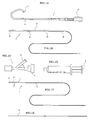
- FIG. 1 is a view showing several devices used when an intravascular foreign matter suction assembly according to an embodiment of the present invention is used.
- reference numeral 1 denotes a guiding catheter (see FIG 1A); 2 denotes a suction catheter(see FIG 1B); 3 denotes a Y-shaped connector serving as a branching connector(see FIG 1C); 4 denotes a syringe serving as a negative pressure generating device(see FIG 1D); 5 denotes a distal end protective catheter(see FIG 1E); and 6 denotes a guide wire(see FIG IF).
- FIG. 2 shows a sectional view of a distal end portion of the guiding catheter 1 of FIG 1A.
- the guiding catheter 1 includes a body portion 11 which in turn includes an inner layer 110 made of a resin material having a sliding property such as a fluorocarbon resin represented by PTFE, a reinforcing layer 111 made of a metal wire made of stainless steel or the like, and an outer layer 112 for covering the reinforcing layer 111, a flexible distal tip 12, and a connector 13 provided at the proximal end of the body portion 11.
- the body portion 11 forms a tubular wall which defines a lumen.
- the flexible distal tip 12 filler such as tungsten, bismuth oxide or barium sulfate which are X-ray contrast agents is mixed by 50 to 70 wt%, and therefore, the flexible distal tip 12 functions as an X-ray contrast marker (radiopaque marker). Therefore, the operator can confirm the position of the distal end portion of the guiding catheter 1 in the body of the patient on an X-ray image.
- X-ray contrast marker radiopaque marker
- FIG 3 shows a sectional view of a distal end portion of the suction catheter 2 of FIG 1B.
- the suction catheter 2 includes a distal side tubular portion 24, and a proximal side wire-like portion 25 formed from a solid metal wire and an outer layer such as a polymer coating.
- the tubular portion 24 includes a tubular body portion 21 which in turn includes an inner layer 210 made of a resin material having a sliding property such as a fluorocarbon resin represented by PTFE, a reinforcing layer 211 made of a metal wire made of stainless steel or the like, and an outer layer 212 for covering the reinforcing layer 211, a distal tip 22 provided at the distal end of the tubular body portion 21, and a proximal tip 23 provided at the proximal end of the tubular body portion 21.
- the tubular portion 24 has an outer diameter with which the tubular portion 24 can be inserted into the lumen of the guiding catheter 1, and the wire-like portion 25 has a sectional area smaller than the sectional area of the tube wall of the tubular portion 24.
- a lubricative coating layer is formed on the surface of the tubular portion 24 by performing hydrophilic lubricative coating which exhibits a high lubricating property when it is wet so that sliding friction of the tubular portion 24 with the inner face of a blood vessel or with the inner surface of the lumen of the guiding catheter 1 is reduced thereby to enhance the insertion feasibility.
- the front free end of the distal tip 22 has a shape inclined obliquely with respect to the longitudinal direction of the distal tip 22 to increase the area of the inlet opening thereof thereby to facilitate suction of a foreign matter and further achieve an effect that the distal end of the suction catheter 2 can advance easily between the foreign matter and the inner wall of the blood vessel.
- the rear end of the proximal tip 23 is similarly inclined obliquely, this is effective to assure the length of the wall for embedding the distal end of the wire-like portion 25 firmly in the proximal tip 23 and assure a large opening area on the proximal end side to enhance the suction force.
- each of the distal tip 22 and the proximal tip 23 is formed such that a filler such as tungsten, bismuth oxide or barium sulfate, which are X-ray contrast agents, is mixed by 50 to 70 wt% in a matrix made of a resin or a matrix made of a metal is plated with gold, it functions as an X-ray contrast marker (radiopaque marker). Consequently, the operator can confirm the positions of the distal end portion of the suction catheter 2 and the proximal end portion of the tubular portion 24 in the body of the patient on an X-ray image.
- a filler such as tungsten, bismuth oxide or barium sulfate, which are X-ray contrast agents
- FIG 4 is a view illustrating an example of a method of joining the wire-like portion 25 and the tubular portion 24 together.
- the proximal tip 23 includes a body which in turn includes a proximal end portion 231 formed by obliquely cutting one end of a metal pipe such as a pipe of stainless steel and a distal end portion 232 formed by working the other end portion of the metal pipe into a spiral shape.
- the inner and outer faces of the body are coated with a resin.
- the proximal end portion 231 is secured firmly by being welded to the distal end of the wire-like portion 25 crushed into a form of a flat plate so that it may not be broken during use.
- the resin layers which cover the inner and outer faces of the proximal tip 23 are secured to the tubular body portion 21 by fusion.
- the proximal tip 23 is formed from such a metal material as described above, the surface of the proximal tip 23 is plated with gold.
- the portion plated with gold functions as an X-ray contrast marker (radiopaque marker).
- the distal end protective catheter 5 of FIG 1E includes a distal end tubular portion 54 which in turn includes a tubular body portion 51, a distal tip 52 provided at the distal end of the tubular body portion 51, a proximal tip 53 provided at the proximal end of the tubular body portion 51, and a proximal end side wire-like portion 55 formed from a metal wire.
- the distal end protective catheter 5 is inserted in the lumen of the suction catheter 2 and projects from the distal end of the suction catheter 2 such that it acts as a protective safety tip upon insertion into a blood vessel.
- the distal tip 52 is made of a flexible material and has a thickness greater than that of the distal tip 22 of the suction catheter 2 and has a rounded extremity.
- the tubular portion 54 and the wire-like portion 55 can be joined together by a method similar to that used for the suction catheter 2 shown in FIG. 4. Also the distal tip 52 and the proximal tip 53 of the distal end protective catheter 5 have a function as a radiopaque marker similarly to those of the suction catheter 2.
- the lumen of the tubular body portion 51 of the distal end protective catheter 5 has a size sufficient to receive the guide wire 6 of FIG 1F therein.
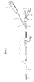
- FIG. 5 shows the devices and so forth shown in FIG 1 in a state wherein they are assembled for use.
- the intravascular foreign matter suction assembly is inserted into a blood vessel in a state illustrated in FIG. 5.
- reference numeral 7 denotes an introducer sheath.
- the introducer sheath 7 is usually used upon ordinary catheter operation, and the introducer sheath 7 is disposed in such a form that it extends from the skin to the inside of a blood vessel thereby to form a path which interconnects the outside of the body and the inside of the blood vessel.
- catheters are inserted into and used while in the introducer sheath 7. Consequently, the burden on the patient such as pain which is caused by a device slidably moving on a damaged portion of the living organism can be reduced.
- the Y-shaped connector 3 of FIG 1C is connected to the connector 13 of the guiding catheter 1; the suction catheter 2 is disposed in the lumen of the guiding catheter 1; the distal end of the distal end protective catheter 5 is inserted in the lumen of the suction catheter 2; and the guide wire 6 is inserted in the lumen of the distal end protective catheter 5.
- the respective proximal ends of the suction catheter 2, the distal end protective catheter 5, and the guide wire 6 are introduced to the outside through a main connector portion 31 of the Y-shaped connector 3.
- a valve (packing) which can close up a bore is built in the main connector portion 31 and can selectively clamp and fix the guide wire 6, the wire-like portion 25 or 55 to prevent leakage of the blood.
- the syringe 4 is connected to a sub connector portion 32 of the Y-shaped connector 3 through a tube 41.
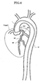
- FIG. 6 illustrates a manner of locating the assembly of the present embodiment is at a target location 80 in a coronary artery of the heart.
- the guiding catheter 1 since the guiding catheter 1 is disposed in the aorta 81 of a comparatively great diameter, it can be formed such that each of the inner and outer diameters of the guiding catheter 1 has a comparatively great dimension.
- the distal end of the guiding catheter 1 is secured in such a form that it is hooked at an ostium 821 of a coronary artery 82.
- the tubular portion 24 of the suction catheter 2 has an outer diameter with which it can be inserted into the coronary artery 82 and is introduced along the guide wire 6 to the target location 80 positioned at a deep location.
- the tubular portion 24 is designed so as to have a sufficient axial length so that the proximal end of the tubular portion 24 in an open state may not leap out from the distal end of the guiding catheter 1 upon such introduction of the tubular portion 24.
- the introduction of the suction catheter 2 and the distal end protective catheter 5 to the deep location is performed by pushing in the wire-like portions 25 and 55 on the proximal end side. Accordingly, the sum total of the lengths in the axial direction of the wire-like portion 25 and the tubular portion 24 and the sum total of the length in the axial direction of the wire-like portion 55 and the tubular portion 54 are designed longer by 50 mm or more than the length of the guiding catheter 1 in the axial direction. If the tubular portion 24 is excessively long, then the suction force decreases, and if the wire-like portion 25 is excessively long, then there is the possibility that the proximal end opening of the tubular portion 24 may project from the distal end of the guiding catheter 1.
- the sum total of the lengths in the axial direction of the wire-like portion 25 and the tubular portion 24 exceeds the length of the guiding catheter 1 in the axial direction by more than 400 mm. Accordingly, it is preferable for the total length of the tubular portion 24 and the wire-like portion 25 of the suction catheter 2 to be greater than the length of the guiding catheter 1 by at least 50 mm but no more than 400 mm.
- the devices mentioned have the following dimensions.
- the guiding catheter 1 preferably has dimensions equal to those of a guiding catheter used in ordinary catheter operation. As a standard length of a guiding catheter used normally, the total length is approximately 1,000 mm. In the following, dimensions of the devices where the length of the guiding catheter 1 is 1,000 mm are given. If the length of the guiding category changes, then also the lengthwise dimensions of the wire-like portions of the devices are preferably changed similarly.
- the length of the tubular portion 24 of the suction catheter 2 is a little greater than a length with which the tubular portion 24 can reach a coronary artery of the heart and particularly is 100 mm to 200 mm.
- the length of the tubular portion 24 is smaller than 100 mm, depending upon the target location, the distal end of the tubular portion 24 cannot sometimes reach the target location, but where the length of the tubular portion 24 is greater than 200 mm, there is the possibility that a preferable suction force may not be obtained.
- the length of the wire-like portion 25 of the suction catheter 2 ranges from 950 mm to 1,200 mm.
- the tubular portion 24 at the distal end of the wire-like portion 25 cannot be extended sufficiently.
- the length of the wire-like portion 25 is greater than 1,200 mm, then there is the possibility that the distal end opening of the tubular portion 24 may project from the distal end of the guiding catheter 1. If the proximal end opening of the tubular portion 24 projects from the distal end of the guiding catheter 1, then upon suction, the blood would be sucked not at the distal end of the suction catheter 2 but at the distal end of the guiding catheter 1.
- the proximal tip 23 provided at the proximal end of the tubular portion 24 has a function of a radiopaque marker, the operator can observe an X-ray image to confirm so that the proximal tip 23 of the suction catheter 2 may not advance farther than the distal end of the guiding catheter 1.
- the length of the tubular portion 54 of the distal end protective catheter 5 preferably ranges from 20 to 50 mm. If the length of the tubular portion 54 were smaller than 20 mm, then the effect of protecting the distal end of the suction catheter 2 when the suction catheter 2 is advanced would not be achieved sufficiently. However, if the length of the tubular portion 54 were longer than 50 mm, then the flexibility of the distal end portion thereof would be insufficient when the tubular portion 54 is combined with the suction catheter 2 to such a degree that it could not be introduced well into a winding blood vessel.
- the guiding catheter 1 is formed from a guiding catheter of 6 Fr (2.06 mm) which is used popularly and has an inner diameter of 1.8 mm.
- the outer diameter of the suction catheter 2 preferably is within a range from 1.65 mm to 1.75 mm.
- the difference between the inner diameter of the guiding catheter 1 and the outer diameter of the suction catheter 2 preferably is within a range from 0.05 mm to 0.15 mm. If the difference is smaller than 0.05 mm, then the passing performance (sliding performance) of the guiding catheter 1 in the suction catheter 2 is low and the convenience in use is poor.
- the difference is greater than 0.15 mm, then when a sucking operation is performed by the syringe 4, the blood is sucked in through the gap (clearance) between the distal end of the guiding catheter 1 and the suction catheter 2, which causes the suction performance from the distal end of the suction catheter 2 to deteriorate. It is to be noted that, since a lubricative coating layer is provided on the surface of the tubular body portion 21 of the suction catheter 2, even where the clearance is small, the suction catheter 2 can move smoothly in the guiding catheter 1.
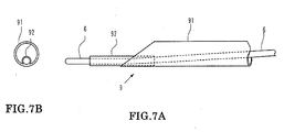
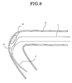
- FIGS. 7A-7B are views showing a modification to the suction catheter of the embodiment described above.
- a guide wire lumen tube 92 having a small diameter is secured to the distal end of a tubular portion 91.
- a proximal end side wire-like portion not shown of the suction catheter 9 has the same structure as that of the embodiment described hereinabove.
- the opening can be directed to a thrombus 80 as seen in FIG 8 and can suck and remove the thrombus 80 efficiently. Further, the necessity for the distal end protective catheter 5 is eliminated.
- the outer diameter of the guide wire lumen tube 92 is smaller than one half the inner diameter of the tubular portion 91 so that the guide wire lumen tube 92 may not make an obstacle to the suction.
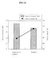
- FIGS. 9A-9B A comparative experiment of the suction force was conducted in a configuration shown in FIGS. 9A-9B using the intravascular foreign matter suction assembly of the example and a straight catheter (total length of 1,100 mm) having a tubular form along the overall length thereof and having inner and outer diameters equal to those of the tubular portion of the suction catheter used in the apparatus of the example.
- the projecting length of the distal end of the suction catheter of the example from the guiding catheter was 100 mm. Accordingly, the effective sectional area used for the suction was 1.6 mm 2 at the distance of 150 mm on the distal end side and 2.1 mm 2 at the distance of 950 mm on the proximal end side (the effective sectional area is given as a value except for the sectional area (0.2 mm 2 ⁇ 2) of the guide wire 6 and the wire-like portion 25 of the suction catheter 2).
- the effective sectional area is 1.6 mm 2 over the overall length (the effective sectional area is given as a value except for the sectional area (0.2 mm 2 ) of the guide wire 6.)
- roller pump serving as a suction apparatus, a pressure gauge and so forth other than the catheters were used commonly to the example and the comparative example.
- a syringe presented as the negative pressure generation means can be replaced by a pump.
Landscapes
- Health & Medical Sciences (AREA)
- Life Sciences & Earth Sciences (AREA)
- Animal Behavior & Ethology (AREA)
- Veterinary Medicine (AREA)
- Public Health (AREA)
- Engineering & Computer Science (AREA)
- Biomedical Technology (AREA)
- Heart & Thoracic Surgery (AREA)
- General Health & Medical Sciences (AREA)
- Anesthesiology (AREA)
- Hematology (AREA)
- Pulmonology (AREA)
- Biophysics (AREA)
- Surgery (AREA)
- Orthopedic Medicine & Surgery (AREA)
- Vascular Medicine (AREA)
- Nuclear Medicine, Radiotherapy & Molecular Imaging (AREA)
- Medical Informatics (AREA)
- Molecular Biology (AREA)
- Surgical Instruments (AREA)
- Media Introduction/Drainage Providing Device (AREA)
- External Artificial Organs (AREA)
Applications Claiming Priority (1)
| Application Number | Priority Date | Filing Date | Title |
|---|---|---|---|
| JP2004276291A JP2006087643A (ja) | 2004-09-24 | 2004-09-24 | 血管内異物吸引装置 |
Publications (2)
| Publication Number | Publication Date |
|---|---|
| EP1639951A1 true EP1639951A1 (de) | 2006-03-29 |
| EP1639951B1 EP1639951B1 (de) | 2009-04-22 |
Family
ID=35462249
Family Applications (1)
| Application Number | Title | Priority Date | Filing Date |
|---|---|---|---|
| EP05020435A Expired - Lifetime EP1639951B1 (de) | 2004-09-24 | 2005-09-20 | Intravaskuläre Sauganordnung zum Ansaugen von Fremdkörpern |
Country Status (5)
| Country | Link |
|---|---|
| US (2) | US7736355B2 (de) |
| EP (1) | EP1639951B1 (de) |
| JP (1) | JP2006087643A (de) |
| AT (1) | ATE429180T1 (de) |
| DE (1) | DE602005014058D1 (de) |
Cited By (27)
| Publication number | Priority date | Publication date | Assignee | Title |
|---|---|---|---|---|
| EP1728531A1 (de) * | 2005-06-01 | 2006-12-06 | Nipro Corporation | Thrombusabsaugkatheter |
| WO2014015308A1 (en) * | 2012-07-19 | 2014-01-23 | Boston Scientific Scimed, Inc. | Guide extension catheter with trackable tip |
| WO2014022310A1 (en) * | 2012-08-01 | 2014-02-06 | Boston Scientific Scimed, Inc. | Guide extension catheters and methods for manufacturing the same |
| WO2014043694A1 (en) * | 2012-09-17 | 2014-03-20 | Boston Scientific Scimed, Inc. | Collarless guide extension catheter |
| EP2391209A4 (de) * | 2009-01-27 | 2014-03-26 | Teleflex Medical Inc | Sputumauflösende ansauglösung für endotracheal- und tracheotomietubus |
| WO2014133897A1 (en) * | 2013-03-01 | 2014-09-04 | Boston Scientific Scimed, Inc. | Guide extension catheter with a retractable wire |
| WO2016126974A1 (en) * | 2015-02-04 | 2016-08-11 | Route 92 Medical, Inc. | Rapid aspiration thrombectomy system and method |
| EP2988684A4 (de) * | 2013-04-23 | 2016-12-21 | Gmedix Inc | Thrombenextraktionskatheter |
| US9681882B2 (en) | 2014-03-21 | 2017-06-20 | Route 92 Medical, Inc. | Rapid aspiration thrombectomy system and method |
| WO2017180398A1 (en) * | 2016-04-14 | 2017-10-19 | Medtronic Vascular Inc. | Guide extension catheter with helically-shaped entry port |
| WO2017214209A1 (en) * | 2016-06-08 | 2017-12-14 | Medtronic Vascular Inc. | Guide extension catheter with grooved push member segment |
| EP3266488A1 (de) * | 2012-01-31 | 2018-01-10 | Boston Scientific Scimed, Inc. | Führungsverlängerungskatheter |
| CN107921235A (zh) * | 2015-06-01 | 2018-04-17 | 波士顿科学国际有限公司 | 引导延伸导管 |
| US10213582B2 (en) | 2013-12-23 | 2019-02-26 | Route 92 Medical, Inc. | Methods and systems for treatment of acute ischemic stroke |
| US10327790B2 (en) | 2011-08-05 | 2019-06-25 | Route 92 Medical, Inc. | Methods and systems for treatment of acute ischemic stroke |
| US10426497B2 (en) | 2015-07-24 | 2019-10-01 | Route 92 Medical, Inc. | Anchoring delivery system and methods |
| EP2874690B1 (de) * | 2012-07-17 | 2021-03-24 | Boston Scientific Scimed, Inc. | Führungsverlängerungskatheter |
| US11020133B2 (en) | 2017-01-10 | 2021-06-01 | Route 92 Medical, Inc. | Aspiration catheter systems and methods of use |
| US11065019B1 (en) | 2015-02-04 | 2021-07-20 | Route 92 Medical, Inc. | Aspiration catheter systems and methods of use |
| US11147699B2 (en) | 2015-07-24 | 2021-10-19 | Route 92 Medical, Inc. | Methods of intracerebral implant delivery |
| US11229770B2 (en) | 2018-05-17 | 2022-01-25 | Route 92 Medical, Inc. | Aspiration catheter systems and methods of use |
| US11490895B2 (en) | 2016-03-03 | 2022-11-08 | Boston Scientific Scimed, Inc. | Guide extension catheter with expandable balloon |
| US11826517B2 (en) | 2016-10-18 | 2023-11-28 | Boston Scientific Scimed, Inc. | Guide extension catheter |
| US12144940B2 (en) | 2020-10-09 | 2024-11-19 | Route 92 Medical, Inc. | Aspiration catheter systems and methods of use |
| US12194247B2 (en) | 2017-01-20 | 2025-01-14 | Route 92 Medical, Inc. | Single operator intracranial medical device delivery systems and methods of use |
| US12262911B2 (en) | 2011-08-05 | 2025-04-01 | Route 92 Medical, Inc. | Methods and systems for treatment of acute ischemic stroke |
| US12471937B2 (en) | 2023-01-25 | 2025-11-18 | Syntheon Pv, Llc | Aspiration thrombectomy systems and methods for thrombus removal with aspiration catheter |
Families Citing this family (62)
| Publication number | Priority date | Publication date | Assignee | Title |
|---|---|---|---|---|
| EP2073723A4 (de) * | 2006-10-10 | 2011-03-30 | Mayo Foundation | Reduzierung kontrastmittelinduzierter toxizität |
| EP2120737B1 (de) | 2007-02-05 | 2020-04-01 | Boston Scientific Limited | Thrombektomie-vorrichtung |
| US11547835B2 (en) | 2018-09-17 | 2023-01-10 | Seigla Medical, Inc. | Systems, methods and apparatus for guiding and supporting catheters and methods of manufacture |
| US11660420B2 (en) | 2018-09-17 | 2023-05-30 | Seigla Medical, Inc. | Catheters and related devices and methods of manufacture |
| EP2259816B1 (de) | 2008-02-20 | 2015-10-21 | Unomedical A/S | Einführungsgerät mit horizontal beweglichem teil |
| US8070694B2 (en) | 2008-07-14 | 2011-12-06 | Medtronic Vascular, Inc. | Fiber based medical devices and aspiration catheters |
| US9510854B2 (en) | 2008-10-13 | 2016-12-06 | Boston Scientific Scimed, Inc. | Thrombectomy catheter with control box having pressure/vacuum valve for synchronous aspiration and fluid irrigation |
| US8784300B2 (en) | 2011-03-30 | 2014-07-22 | Children's Hospital & Research Center Oakland | Devices, systems, and methods for removing empyema from a pleural cavity |
| US20120259314A1 (en) * | 2011-04-11 | 2012-10-11 | Medtronic Vascular, Inc. | Apparatus and Methods for Recanalization of a Chronic Total Occlusion |
| EP2776108B1 (de) | 2011-11-09 | 2019-07-17 | Boston Scientific Scimed, Inc. | Führungsverlängerungskatheter |
| EP2872210A1 (de) * | 2012-07-13 | 2015-05-20 | Boston Scientific Scimed, Inc. | Führungsverlängerungskatheter |
| US10898680B2 (en) | 2013-03-15 | 2021-01-26 | Qxmedical, Llc | Boosting catheter and related systems and methods |
| US9144662B2 (en) | 2013-03-15 | 2015-09-29 | Qxmedical, Llc | Boosting catheter and related systems and methods |
| JP6045067B2 (ja) * | 2013-04-22 | 2016-12-14 | 朝日インテック株式会社 | 吸引カテーテル組立体 |
| US10322260B2 (en) * | 2013-05-30 | 2019-06-18 | Terumo Kabushiki Kaisha | Treatment method for treating lower limbs using multi-member catheter assembly |
| US9433427B2 (en) | 2014-04-08 | 2016-09-06 | Incuvate, Llc | Systems and methods for management of thrombosis |
| US9248221B2 (en) | 2014-04-08 | 2016-02-02 | Incuvate, Llc | Aspiration monitoring system and method |
| US9883877B2 (en) | 2014-05-19 | 2018-02-06 | Walk Vascular, Llc | Systems and methods for removal of blood and thrombotic material |
| US10617847B2 (en) | 2014-11-04 | 2020-04-14 | Orbusneich Medical Pte. Ltd. | Variable flexibility catheter support frame |
| HK1243662A1 (zh) | 2014-11-04 | 2018-07-20 | 祥丰医疗私人有限公司 | 柔韧性渐变的导管支撑框架 |
| EP3302674B1 (de) | 2015-05-26 | 2019-01-30 | Teleflex Innovations S.à.r.l. | Führungsdrahtfixierung |
| US10702292B2 (en) | 2015-08-28 | 2020-07-07 | Incuvate, Llc | Aspiration monitoring system and method |
| US10561440B2 (en) * | 2015-09-03 | 2020-02-18 | Vesatek, Llc | Systems and methods for manipulating medical devices |
| US10688277B2 (en) | 2015-09-23 | 2020-06-23 | Medtronic Vascular, Inc. | Guide extension catheter with perfusion openings |
| US11986607B2 (en) | 2015-10-01 | 2024-05-21 | Qxmedical, Llc | Catheter structure with improved support and related systems, methods, and devices |
| US20170100142A1 (en) | 2015-10-09 | 2017-04-13 | Incuvate, Llc | Systems and methods for management of thrombosis |
| US10716915B2 (en) | 2015-11-23 | 2020-07-21 | Mivi Neuroscience, Inc. | Catheter systems for applying effective suction in remote vessels and thrombectomy procedures facilitated by catheter systems |
| US10226263B2 (en) | 2015-12-23 | 2019-03-12 | Incuvate, Llc | Aspiration monitoring system and method |
| WO2017117190A1 (en) | 2015-12-28 | 2017-07-06 | Gonzalez Luis Fernando | Delivery catheter with fixed guidewire and beveled elliptical port |
| CN113368367B (zh) * | 2016-02-24 | 2024-03-29 | 禾木(中国)生物工程有限公司 | 柔性增强的神经血管导管 |
| US10492805B2 (en) | 2016-04-06 | 2019-12-03 | Walk Vascular, Llc | Systems and methods for thrombolysis and delivery of an agent |
| US10751514B2 (en) | 2016-12-09 | 2020-08-25 | Teleflex Life Sciences Limited | Guide extension catheter |
| JP7000417B2 (ja) | 2017-03-31 | 2022-02-10 | テルモ株式会社 | 医療用長尺体および医療器具セット |
| US10478535B2 (en) | 2017-05-24 | 2019-11-19 | Mivi Neuroscience, Inc. | Suction catheter systems for applying effective aspiration in remote vessels, especially cerebral arteries |
| US11234723B2 (en) * | 2017-12-20 | 2022-02-01 | Mivi Neuroscience, Inc. | Suction catheter systems for applying effective aspiration in remote vessels, especially cerebral arteries |
| CN107096120B (zh) * | 2017-06-01 | 2023-03-21 | 依奈德医疗技术(上海)有限公司 | 用于心脏介入治疗的冠状动脉输送导管、导管和装置 |
| CN119405388A (zh) | 2018-05-01 | 2025-02-11 | 因赛普特有限责任公司 | 用于从血管内部位去除闭塞性物质的装置和方法 |
| JP7353303B2 (ja) | 2018-06-05 | 2023-09-29 | メドトロニック・ヴァスキュラー・インコーポレーテッド | 医療用カテーテル |
| US11911573B2 (en) | 2018-06-05 | 2024-02-27 | Medtronic Vascular, Inc. | Medical catheter |
| US11559663B2 (en) | 2018-06-05 | 2023-01-24 | Medtronic Vascular, Inc. | Catheter including slidable push grip |
| US11278707B2 (en) | 2018-06-14 | 2022-03-22 | Stryker Corporation | Balloon catheter assembly for insertion and positioning therapeutic devices within a vascular system |
| US11471582B2 (en) | 2018-07-06 | 2022-10-18 | Incept, Llc | Vacuum transfer tool for extendable catheter |
| US11678905B2 (en) | 2018-07-19 | 2023-06-20 | Walk Vascular, Llc | Systems and methods for removal of blood and thrombotic material |
| US11400255B1 (en) | 2018-11-15 | 2022-08-02 | Route 92 Medical, Inc. | Aspiration catheter systems and methods of use |
| US11524142B2 (en) | 2018-11-27 | 2022-12-13 | Teleflex Life Sciences Limited | Guide extension catheter |
| WO2020131227A1 (en) | 2018-12-19 | 2020-06-25 | Teleflex Life Sciences Limited | Guide extension catheter |
| JP7539606B2 (ja) | 2019-01-07 | 2024-08-26 | テレフレックス ライフ サイエンシズ リミテッド ライアビリティ カンパニー | ガイド延長カテーテル |
| US11766539B2 (en) | 2019-03-29 | 2023-09-26 | Incept, Llc | Enhanced flexibility neurovascular catheter |
| GB201917184D0 (en) * | 2019-11-26 | 2020-01-08 | Univ Sheffield | Guiding device for a vascular catheter |
| CA3162704A1 (en) | 2019-12-18 | 2021-06-24 | Imperative Care, Inc. | Methods and systems for treating venous thromboembolic disease |
| US20230248498A1 (en) | 2019-12-18 | 2023-08-10 | Imperative Care, Inc. | Manually rotatable thrombus engagement tool |
| US11439799B2 (en) | 2019-12-18 | 2022-09-13 | Imperative Care, Inc. | Split dilator aspiration system |
| US11617865B2 (en) | 2020-01-24 | 2023-04-04 | Mivi Neuroscience, Inc. | Suction catheter systems with designs allowing rapid clearing of clots |
| US12274458B2 (en) | 2021-02-15 | 2025-04-15 | Walk Vascular, Llc | Systems and methods for removal of blood and thrombotic material |
| EP4291261A1 (de) | 2021-02-15 | 2023-12-20 | Walk Vascular, LLC | Systeme und verfahren zur entfernung von blut und thrombotischem material |
| EP4329643A4 (de) | 2021-04-27 | 2025-03-12 | Contego Medical, Inc. | Thrombusaspirationssystem und verfahren zur kontrolle von blutverlust |
| US20230047098A1 (en) | 2021-08-12 | 2023-02-16 | Imperative Care, Inc. | Multi catheter method of performing a robotic neurovascular procedure |
| USD1077996S1 (en) | 2021-10-18 | 2025-06-03 | Imperative Care, Inc. | Inline fluid filter |
| USD1071209S1 (en) | 2022-06-29 | 2025-04-15 | Cardiovascular Systems, Inc. | Partial flared guide extension catheter |
| USD1071208S1 (en) | 2022-06-29 | 2025-04-15 | Cardiovascular Systems, Inc. | Guide extension catheter |
| US12171917B1 (en) | 2024-01-08 | 2024-12-24 | Imperative Care, Inc. | Devices for blood capture and reintroduction during aspiration procedure |
| CN119524291B (zh) * | 2024-12-26 | 2025-09-23 | 开封市中心医院 | 一种用于介入手术的抽吸导管 |
Citations (5)
| Publication number | Priority date | Publication date | Assignee | Title |
|---|---|---|---|---|
| US5527292A (en) * | 1990-10-29 | 1996-06-18 | Scimed Life Systems, Inc. | Intravascular device for coronary heart treatment |
| US5938645A (en) * | 1995-05-24 | 1999-08-17 | Boston Scientific Corporation Northwest Technology Center Inc. | Percutaneous aspiration catheter system |
| WO2000069498A1 (en) * | 1999-05-14 | 2000-11-23 | Boston Scientific Limited | Drainage catheter delivery system |
| US20020177800A1 (en) * | 2001-04-16 | 2002-11-28 | Bagaoisan Celso J. | Aspiration catheters and method of use |
| US20030050600A1 (en) * | 2001-05-01 | 2003-03-13 | Velocimed, L.L.C. | Emboli protection devices and related methods of use |
Family Cites Families (5)
| Publication number | Priority date | Publication date | Assignee | Title |
|---|---|---|---|---|
| US5011488A (en) * | 1988-12-07 | 1991-04-30 | Robert Ginsburg | Thrombus extraction system |
| JPH06502331A (ja) * | 1990-10-29 | 1994-03-17 | サイメッド・ライフ・システムズ・インコーポレーテッド | 血管形成術ガイドカテーテル用のガイドカテーテル装置 |
| US5226888A (en) * | 1991-10-25 | 1993-07-13 | Michelle Arney | Coiled, perfusion balloon catheter |
| ES2123019T3 (es) | 1993-06-24 | 1999-01-01 | Schneider Europ Gmbh | Cateter de aspiracion. |
| US6849068B1 (en) * | 1997-03-06 | 2005-02-01 | Medtronic Ave, Inc. | Aspiration catheter |
-
2004
- 2004-09-24 JP JP2004276291A patent/JP2006087643A/ja active Pending
-
2005
- 2005-09-20 DE DE602005014058T patent/DE602005014058D1/de not_active Expired - Lifetime
- 2005-09-20 AT AT05020435T patent/ATE429180T1/de not_active IP Right Cessation
- 2005-09-20 EP EP05020435A patent/EP1639951B1/de not_active Expired - Lifetime
- 2005-09-23 US US11/232,876 patent/US7736355B2/en active Active
-
2010
- 2010-04-28 US US12/769,066 patent/US8764724B2/en active Active
Patent Citations (5)
| Publication number | Priority date | Publication date | Assignee | Title |
|---|---|---|---|---|
| US5527292A (en) * | 1990-10-29 | 1996-06-18 | Scimed Life Systems, Inc. | Intravascular device for coronary heart treatment |
| US5938645A (en) * | 1995-05-24 | 1999-08-17 | Boston Scientific Corporation Northwest Technology Center Inc. | Percutaneous aspiration catheter system |
| WO2000069498A1 (en) * | 1999-05-14 | 2000-11-23 | Boston Scientific Limited | Drainage catheter delivery system |
| US20020177800A1 (en) * | 2001-04-16 | 2002-11-28 | Bagaoisan Celso J. | Aspiration catheters and method of use |
| US20030050600A1 (en) * | 2001-05-01 | 2003-03-13 | Velocimed, L.L.C. | Emboli protection devices and related methods of use |
Cited By (81)
| Publication number | Priority date | Publication date | Assignee | Title |
|---|---|---|---|---|
| EP1728531A1 (de) * | 2005-06-01 | 2006-12-06 | Nipro Corporation | Thrombusabsaugkatheter |
| EP2391209A4 (de) * | 2009-01-27 | 2014-03-26 | Teleflex Medical Inc | Sputumauflösende ansauglösung für endotracheal- und tracheotomietubus |
| US10327790B2 (en) | 2011-08-05 | 2019-06-25 | Route 92 Medical, Inc. | Methods and systems for treatment of acute ischemic stroke |
| US10743893B2 (en) | 2011-08-05 | 2020-08-18 | Route 92 Medical, Inc. | Methods and systems for treatment of acute ischemic stroke |
| US10646239B2 (en) | 2011-08-05 | 2020-05-12 | Route 92 Medical, Inc. | Methods and systems for treatment of acute ischemic stroke |
| US10722251B2 (en) | 2011-08-05 | 2020-07-28 | Route 92 Medical, Inc. | Methods and systems for treatment of acute ischemic stroke |
| US12262911B2 (en) | 2011-08-05 | 2025-04-01 | Route 92 Medical, Inc. | Methods and systems for treatment of acute ischemic stroke |
| US11871944B2 (en) | 2011-08-05 | 2024-01-16 | Route 92 Medical, Inc. | Methods and systems for treatment of acute ischemic stroke |
| US12343036B2 (en) | 2011-08-05 | 2025-07-01 | Route 92 Medical, Inc. | Methods and systems for treatment of acute ischemic stroke |
| EP3266488A1 (de) * | 2012-01-31 | 2018-01-10 | Boston Scientific Scimed, Inc. | Führungsverlängerungskatheter |
| EP2874690B1 (de) * | 2012-07-17 | 2021-03-24 | Boston Scientific Scimed, Inc. | Führungsverlängerungskatheter |
| WO2014015308A1 (en) * | 2012-07-19 | 2014-01-23 | Boston Scientific Scimed, Inc. | Guide extension catheter with trackable tip |
| US10124148B2 (en) | 2012-07-19 | 2018-11-13 | Boston Scientific Scimed, Inc. | Guide extension catheter with trackable tip and related methods of use |
| WO2014022310A1 (en) * | 2012-08-01 | 2014-02-06 | Boston Scientific Scimed, Inc. | Guide extension catheters and methods for manufacturing the same |
| EP3042685A1 (de) * | 2012-09-17 | 2016-07-13 | Boston Scientific Scimed, Inc. | Katheter mit kragenloser führungsverlängerung |
| US9352123B2 (en) | 2012-09-17 | 2016-05-31 | Boston Scientific Scime, Inc. | Collarless guide extension catheter |
| WO2014043694A1 (en) * | 2012-09-17 | 2014-03-20 | Boston Scientific Scimed, Inc. | Collarless guide extension catheter |
| WO2014133897A1 (en) * | 2013-03-01 | 2014-09-04 | Boston Scientific Scimed, Inc. | Guide extension catheter with a retractable wire |
| CN105163789A (zh) * | 2013-03-01 | 2015-12-16 | 波士顿科学国际有限公司 | 具有可伸缩线的引导延伸导管 |
| US10130379B2 (en) | 2013-04-23 | 2018-11-20 | Normedix, Inc. | Thrombus extraction catheter |
| US11129629B2 (en) | 2013-04-23 | 2021-09-28 | Normedix, Inc. | Thrombus extraction catheter |
| EP2988684A4 (de) * | 2013-04-23 | 2016-12-21 | Gmedix Inc | Thrombenextraktionskatheter |
| US11534575B2 (en) | 2013-12-23 | 2022-12-27 | Route 92 Medical, Inc. | Methods and systems for treatment of acute ischemic stroke |
| US10213582B2 (en) | 2013-12-23 | 2019-02-26 | Route 92 Medical, Inc. | Methods and systems for treatment of acute ischemic stroke |
| US12343480B2 (en) | 2013-12-23 | 2025-07-01 | Route 92 Medical, Inc. | Methods and systems for treatment of acute ischemic stroke |
| US11318282B2 (en) | 2013-12-23 | 2022-05-03 | Route 92 Medical, Inc. | Methods and systems for treatment of acute ischemic stroke |
| US10471233B2 (en) | 2013-12-23 | 2019-11-12 | Route 92 Medical, Inc. | Methods and systems for treatment of acute ischemic stroke |
| US12115320B2 (en) | 2013-12-23 | 2024-10-15 | Route 92 Medical, Inc. | Methods and systems for treatment of acute ischemic stroke |
| US10569049B2 (en) | 2013-12-23 | 2020-02-25 | Route 92 Medical, Inc. | Methods and systems for treatment of acute ischemic stroke |
| US10864351B2 (en) | 2013-12-23 | 2020-12-15 | Route 92 Medical, Inc. | Methods and systems for treatment of acute ischemic stroke |
| US9681882B2 (en) | 2014-03-21 | 2017-06-20 | Route 92 Medical, Inc. | Rapid aspiration thrombectomy system and method |
| US9820761B2 (en) | 2014-03-21 | 2017-11-21 | Route 92 Medical, Inc. | Rapid aspiration thrombectomy system and method |
| US11065019B1 (en) | 2015-02-04 | 2021-07-20 | Route 92 Medical, Inc. | Aspiration catheter systems and methods of use |
| US11383064B2 (en) | 2015-02-04 | 2022-07-12 | Route 92 Medical, Inc. | Rapid aspiration thrombectomy system and method |
| WO2016126974A1 (en) * | 2015-02-04 | 2016-08-11 | Route 92 Medical, Inc. | Rapid aspiration thrombectomy system and method |
| AU2016215229B2 (en) * | 2015-02-04 | 2020-05-07 | Route 92 Medical, Inc. | Rapid aspiration thrombectomy system and method |
| US10485952B2 (en) | 2015-02-04 | 2019-11-26 | Route 92 Medical, Inc. | Rapid aspiration thrombectomy system and method |
| CN107405159A (zh) * | 2015-02-04 | 2017-11-28 | 92号医疗公司 | 快速抽吸血栓清除系统和方法 |
| US11806032B2 (en) | 2015-02-04 | 2023-11-07 | Route 92 Medical, Inc. | Aspiration catheter systems and methods of use |
| US11793972B2 (en) | 2015-02-04 | 2023-10-24 | Route 92 Medical, Inc. | Rapid aspiration thrombectomy system and method |
| US10456555B2 (en) | 2015-02-04 | 2019-10-29 | Route 92 Medical, Inc. | Rapid aspiration thrombectomy system and method |
| US11793529B2 (en) | 2015-02-04 | 2023-10-24 | Route 92 Medical, Inc. | Aspiration catheter systems and methods of use |
| US11633571B2 (en) | 2015-02-04 | 2023-04-25 | Route 92 Medical, Inc. | Rapid aspiration thrombectomy system and method |
| US11185664B2 (en) | 2015-02-04 | 2021-11-30 | Route 92 Medical, Inc. | Rapid aspiration thrombectomy system and method |
| US11224721B2 (en) | 2015-02-04 | 2022-01-18 | Route 92 Medical, Inc. | Rapid aspiration thrombectomy system and method |
| US11224450B2 (en) | 2015-02-04 | 2022-01-18 | Route 92 Medical, Inc. | Aspiration catheter systems and methods of use |
| US11633570B2 (en) | 2015-02-04 | 2023-04-25 | Route 92 Medical, Inc. | Rapid aspiration thrombectomy system and method |
| US11576691B2 (en) | 2015-02-04 | 2023-02-14 | Route 92 Medical, Inc. | Aspiration catheter systems and methods of use |
| AU2020205209B2 (en) * | 2015-02-04 | 2022-04-07 | Route 92 Medical, Inc. | Rapid aspiration thrombectomy system and method |
| US11305094B2 (en) | 2015-02-04 | 2022-04-19 | Route 92 Medical, Inc. | Rapid aspiration thrombectomy system and method |
| US11395903B2 (en) | 2015-02-04 | 2022-07-26 | Route 92 Medical, Inc. | Rapid aspiration thrombectomy system and method |
| US11571545B2 (en) | 2015-06-01 | 2023-02-07 | Boston Scientific Scimed, Inc. | Guide extension catheter |
| US12239798B2 (en) | 2015-06-01 | 2025-03-04 | Boston Scientific Scimed, Inc. | Guide extension catheter |
| US10682494B2 (en) | 2015-06-01 | 2020-06-16 | Boston Scientific Scimed, Inc. | Guide extension catheter |
| CN107921235B (zh) * | 2015-06-01 | 2021-05-28 | 波士顿科学国际有限公司 | 引导延伸导管 |
| CN107921235A (zh) * | 2015-06-01 | 2018-04-17 | 波士顿科学国际有限公司 | 引导延伸导管 |
| US11147699B2 (en) | 2015-07-24 | 2021-10-19 | Route 92 Medical, Inc. | Methods of intracerebral implant delivery |
| US10426497B2 (en) | 2015-07-24 | 2019-10-01 | Route 92 Medical, Inc. | Anchoring delivery system and methods |
| US12213688B2 (en) | 2015-07-24 | 2025-02-04 | Route 92 Medical, Inc. | Anchoring delivery system and methods |
| US11998468B2 (en) | 2015-07-24 | 2024-06-04 | Route 92 Medical, Inc. | Methods of intracerebral implant delivery |
| US11224449B2 (en) | 2015-07-24 | 2022-01-18 | Route 92 Medical, Inc. | Anchoring delivery system and methods |
| US11490895B2 (en) | 2016-03-03 | 2022-11-08 | Boston Scientific Scimed, Inc. | Guide extension catheter with expandable balloon |
| US10729884B2 (en) | 2016-04-14 | 2020-08-04 | Medtronic Vascular, Inc. | Guide extension catheter with helically-shaped entry port |
| WO2017180398A1 (en) * | 2016-04-14 | 2017-10-19 | Medtronic Vascular Inc. | Guide extension catheter with helically-shaped entry port |
| US11547834B2 (en) | 2016-04-14 | 2023-01-10 | Medtronic Vascular, Inc. | Guide extension catheter with helically-shaped entry port |
| CN109310846A (zh) * | 2016-06-08 | 2019-02-05 | 美敦力瓦斯科尔勒公司 | 具有带凹槽的推动构件节段的引导延伸导管 |
| WO2017214209A1 (en) * | 2016-06-08 | 2017-12-14 | Medtronic Vascular Inc. | Guide extension catheter with grooved push member segment |
| US10485956B2 (en) | 2016-06-08 | 2019-11-26 | Medtronic Vascular, Inc. | Guide extension catheter with grooved push member segment |
| CN109310846B (zh) * | 2016-06-08 | 2021-10-15 | 美敦力瓦斯科尔勒公司 | 具有带凹槽的推动构件节段的引导延伸导管 |
| US12290642B2 (en) | 2016-10-18 | 2025-05-06 | Boston Scientific Scimed, Inc. | Guide extension catheter |
| US11826517B2 (en) | 2016-10-18 | 2023-11-28 | Boston Scientific Scimed, Inc. | Guide extension catheter |
| US11020133B2 (en) | 2017-01-10 | 2021-06-01 | Route 92 Medical, Inc. | Aspiration catheter systems and methods of use |
| US12295595B2 (en) | 2017-01-10 | 2025-05-13 | Route 92 Medical, Inc. | Aspiration catheter systems and methods of use |
| US11399852B2 (en) | 2017-01-10 | 2022-08-02 | Route 92 Medical, Inc. | Aspiration catheter systems and methods of use |
| US12194247B2 (en) | 2017-01-20 | 2025-01-14 | Route 92 Medical, Inc. | Single operator intracranial medical device delivery systems and methods of use |
| US11229770B2 (en) | 2018-05-17 | 2022-01-25 | Route 92 Medical, Inc. | Aspiration catheter systems and methods of use |
| US11607523B2 (en) | 2018-05-17 | 2023-03-21 | Route 92 Medical, Inc. | Aspiration catheter systems and methods of use |
| US11925770B2 (en) | 2018-05-17 | 2024-03-12 | Route 92 Medical, Inc. | Aspiration catheter systems and methods of use |
| US12383702B2 (en) | 2018-05-17 | 2025-08-12 | Route 92 Medical, Inc. | Aspiration catheter systems and methods of use |
| US12144940B2 (en) | 2020-10-09 | 2024-11-19 | Route 92 Medical, Inc. | Aspiration catheter systems and methods of use |
| US12471937B2 (en) | 2023-01-25 | 2025-11-18 | Syntheon Pv, Llc | Aspiration thrombectomy systems and methods for thrombus removal with aspiration catheter |
Also Published As
| Publication number | Publication date |
|---|---|
| ATE429180T1 (de) | 2009-05-15 |
| US8764724B2 (en) | 2014-07-01 |
| US20060069381A1 (en) | 2006-03-30 |
| US20100217237A1 (en) | 2010-08-26 |
| JP2006087643A (ja) | 2006-04-06 |
| US7736355B2 (en) | 2010-06-15 |
| DE602005014058D1 (de) | 2009-06-04 |
| EP1639951B1 (de) | 2009-04-22 |
Similar Documents
| Publication | Publication Date | Title |
|---|---|---|
| EP1639951B1 (de) | Intravaskuläre Sauganordnung zum Ansaugen von Fremdkörpern | |
| US8241315B2 (en) | Apparatus and method for treating occluded vasculature | |
| US11065020B2 (en) | Suction catheter, suction system, and treatment method | |
| KR101166445B1 (ko) | 흡인 카테터 | |
| JP5381703B2 (ja) | 血栓吸引カテーテル | |
| US8313493B2 (en) | Hydraulic guidewire advancement system | |
| US20170333060A1 (en) | Catheter assembly for blood clots removal | |
| JP7640040B2 (ja) | 調製不要なバルーン・ガイド・カテーテル | |
| US20100204672A1 (en) | System and method for treating ischemic stroke | |
| US20120232570A1 (en) | Apparatus and method for treating occluded vasculature | |
| US12144940B2 (en) | Aspiration catheter systems and methods of use | |
| EP3967357A1 (de) | Ballonkatheter mit verbesserter flexibilität | |
| JP2009542413A (ja) | 脈管カテーテル装置および方法 | |
| JP4518044B2 (ja) | 血栓吸引カテーテル | |
| US20250235234A1 (en) | Deployable dynamic stent and adjustable cutting jet device | |
| US20230149696A1 (en) | Device Delivery Tool | |
| CN118477216A (zh) | 导引抽吸导管及具有该导管的导管系统 | |
| EP4233976A1 (de) | Katheter und drosselkatheter | |
| US20230068943A1 (en) | Flow blocking catheter | |
| JP2007202614A (ja) | カテーテル |
Legal Events
| Date | Code | Title | Description |
|---|---|---|---|
| PUAI | Public reference made under article 153(3) epc to a published international application that has entered the european phase |
Free format text: ORIGINAL CODE: 0009012 |
|
| AK | Designated contracting states |
Kind code of ref document: A1 Designated state(s): AT BE BG CH CY CZ DE DK EE ES FI FR GB GR HU IE IS IT LI LT LU LV MC NL PL PT RO SE SI SK TR |
|
| AX | Request for extension of the european patent |
Extension state: AL BA HR MK YU |
|
| 17P | Request for examination filed |
Effective date: 20060908 |
|
| 17Q | First examination report despatched |
Effective date: 20061018 |
|
| AKX | Designation fees paid |
Designated state(s): AT BE BG CH CY CZ DE DK EE ES FI FR GB GR HU IE IS IT LI LT LU LV MC NL PL PT RO SE SI SK TR |
|
| GRAP | Despatch of communication of intention to grant a patent |
Free format text: ORIGINAL CODE: EPIDOSNIGR1 |
|
| GRAS | Grant fee paid |
Free format text: ORIGINAL CODE: EPIDOSNIGR3 |
|
| GRAA | (expected) grant |
Free format text: ORIGINAL CODE: 0009210 |
|
| RIN1 | Information on inventor provided before grant (corrected) |
Inventor name: FUKUOKA, TETSUYA Inventor name: ITOU, TAKENARI |
|
| AK | Designated contracting states |
Kind code of ref document: B1 Designated state(s): AT BE BG CH CY CZ DE DK EE ES FI FR GB GR HU IE IS IT LI LT LU LV MC NL PL PT RO SE SI SK TR |
|
| REG | Reference to a national code |
Ref country code: GB Ref legal event code: FG4D |
|
| REG | Reference to a national code |
Ref country code: CH Ref legal event code: EP |
|
| REG | Reference to a national code |
Ref country code: IE Ref legal event code: FG4D |
|
| REF | Corresponds to: |
Ref document number: 602005014058 Country of ref document: DE Date of ref document: 20090604 Kind code of ref document: P |
|
| NLV1 | Nl: lapsed or annulled due to failure to fulfill the requirements of art. 29p and 29m of the patents act | ||
| PG25 | Lapsed in a contracting state [announced via postgrant information from national office to epo] |
Ref country code: FI Free format text: LAPSE BECAUSE OF FAILURE TO SUBMIT A TRANSLATION OF THE DESCRIPTION OR TO PAY THE FEE WITHIN THE PRESCRIBED TIME-LIMIT Effective date: 20090422 Ref country code: LT Free format text: LAPSE BECAUSE OF FAILURE TO SUBMIT A TRANSLATION OF THE DESCRIPTION OR TO PAY THE FEE WITHIN THE PRESCRIBED TIME-LIMIT Effective date: 20090422 Ref country code: PT Free format text: LAPSE BECAUSE OF FAILURE TO SUBMIT A TRANSLATION OF THE DESCRIPTION OR TO PAY THE FEE WITHIN THE PRESCRIBED TIME-LIMIT Effective date: 20090822 Ref country code: AT Free format text: LAPSE BECAUSE OF FAILURE TO SUBMIT A TRANSLATION OF THE DESCRIPTION OR TO PAY THE FEE WITHIN THE PRESCRIBED TIME-LIMIT Effective date: 20090422 Ref country code: ES Free format text: LAPSE BECAUSE OF FAILURE TO SUBMIT A TRANSLATION OF THE DESCRIPTION OR TO PAY THE FEE WITHIN THE PRESCRIBED TIME-LIMIT Effective date: 20090802 |
|
| PG25 | Lapsed in a contracting state [announced via postgrant information from national office to epo] |
Ref country code: SI Free format text: LAPSE BECAUSE OF FAILURE TO SUBMIT A TRANSLATION OF THE DESCRIPTION OR TO PAY THE FEE WITHIN THE PRESCRIBED TIME-LIMIT Effective date: 20090422 Ref country code: LV Free format text: LAPSE BECAUSE OF FAILURE TO SUBMIT A TRANSLATION OF THE DESCRIPTION OR TO PAY THE FEE WITHIN THE PRESCRIBED TIME-LIMIT Effective date: 20090422 Ref country code: IS Free format text: LAPSE BECAUSE OF FAILURE TO SUBMIT A TRANSLATION OF THE DESCRIPTION OR TO PAY THE FEE WITHIN THE PRESCRIBED TIME-LIMIT Effective date: 20090822 Ref country code: SE Free format text: LAPSE BECAUSE OF FAILURE TO SUBMIT A TRANSLATION OF THE DESCRIPTION OR TO PAY THE FEE WITHIN THE PRESCRIBED TIME-LIMIT Effective date: 20090722 Ref country code: NL Free format text: LAPSE BECAUSE OF FAILURE TO SUBMIT A TRANSLATION OF THE DESCRIPTION OR TO PAY THE FEE WITHIN THE PRESCRIBED TIME-LIMIT Effective date: 20090422 Ref country code: PL Free format text: LAPSE BECAUSE OF FAILURE TO SUBMIT A TRANSLATION OF THE DESCRIPTION OR TO PAY THE FEE WITHIN THE PRESCRIBED TIME-LIMIT Effective date: 20090422 |
|
| PG25 | Lapsed in a contracting state [announced via postgrant information from national office to epo] |
Ref country code: DK Free format text: LAPSE BECAUSE OF FAILURE TO SUBMIT A TRANSLATION OF THE DESCRIPTION OR TO PAY THE FEE WITHIN THE PRESCRIBED TIME-LIMIT Effective date: 20090422 Ref country code: EE Free format text: LAPSE BECAUSE OF FAILURE TO SUBMIT A TRANSLATION OF THE DESCRIPTION OR TO PAY THE FEE WITHIN THE PRESCRIBED TIME-LIMIT Effective date: 20090422 Ref country code: RO Free format text: LAPSE BECAUSE OF FAILURE TO SUBMIT A TRANSLATION OF THE DESCRIPTION OR TO PAY THE FEE WITHIN THE PRESCRIBED TIME-LIMIT Effective date: 20090422 Ref country code: CZ Free format text: LAPSE BECAUSE OF FAILURE TO SUBMIT A TRANSLATION OF THE DESCRIPTION OR TO PAY THE FEE WITHIN THE PRESCRIBED TIME-LIMIT Effective date: 20090422 |
|
| PG25 | Lapsed in a contracting state [announced via postgrant information from national office to epo] |
Ref country code: BE Free format text: LAPSE BECAUSE OF FAILURE TO SUBMIT A TRANSLATION OF THE DESCRIPTION OR TO PAY THE FEE WITHIN THE PRESCRIBED TIME-LIMIT Effective date: 20090422 Ref country code: SK Free format text: LAPSE BECAUSE OF FAILURE TO SUBMIT A TRANSLATION OF THE DESCRIPTION OR TO PAY THE FEE WITHIN THE PRESCRIBED TIME-LIMIT Effective date: 20090422 |
|
| PLBE | No opposition filed within time limit |
Free format text: ORIGINAL CODE: 0009261 |
|
| STAA | Information on the status of an ep patent application or granted ep patent |
Free format text: STATUS: NO OPPOSITION FILED WITHIN TIME LIMIT |
|
| 26N | No opposition filed |
Effective date: 20100125 |
|
| PG25 | Lapsed in a contracting state [announced via postgrant information from national office to epo] |
Ref country code: BG Free format text: LAPSE BECAUSE OF FAILURE TO SUBMIT A TRANSLATION OF THE DESCRIPTION OR TO PAY THE FEE WITHIN THE PRESCRIBED TIME-LIMIT Effective date: 20090722 |
|
| PG25 | Lapsed in a contracting state [announced via postgrant information from national office to epo] |
Ref country code: MC Free format text: LAPSE BECAUSE OF NON-PAYMENT OF DUE FEES Effective date: 20090930 |
|
| REG | Reference to a national code |
Ref country code: CH Ref legal event code: PL |
|
| PG25 | Lapsed in a contracting state [announced via postgrant information from national office to epo] |
Ref country code: IE Free format text: LAPSE BECAUSE OF NON-PAYMENT OF DUE FEES Effective date: 20090920 |
|
| PG25 | Lapsed in a contracting state [announced via postgrant information from national office to epo] |
Ref country code: LI Free format text: LAPSE BECAUSE OF NON-PAYMENT OF DUE FEES Effective date: 20090930 Ref country code: CH Free format text: LAPSE BECAUSE OF NON-PAYMENT OF DUE FEES Effective date: 20090930 Ref country code: GR Free format text: LAPSE BECAUSE OF FAILURE TO SUBMIT A TRANSLATION OF THE DESCRIPTION OR TO PAY THE FEE WITHIN THE PRESCRIBED TIME-LIMIT Effective date: 20090723 |
|
| PG25 | Lapsed in a contracting state [announced via postgrant information from national office to epo] |
Ref country code: IT Free format text: LAPSE BECAUSE OF FAILURE TO SUBMIT A TRANSLATION OF THE DESCRIPTION OR TO PAY THE FEE WITHIN THE PRESCRIBED TIME-LIMIT Effective date: 20090422 |
|
| PG25 | Lapsed in a contracting state [announced via postgrant information from national office to epo] |
Ref country code: LU Free format text: LAPSE BECAUSE OF NON-PAYMENT OF DUE FEES Effective date: 20090920 |
|
| PG25 | Lapsed in a contracting state [announced via postgrant information from national office to epo] |
Ref country code: HU Free format text: LAPSE BECAUSE OF FAILURE TO SUBMIT A TRANSLATION OF THE DESCRIPTION OR TO PAY THE FEE WITHIN THE PRESCRIBED TIME-LIMIT Effective date: 20091023 |
|
| PG25 | Lapsed in a contracting state [announced via postgrant information from national office to epo] |
Ref country code: TR Free format text: LAPSE BECAUSE OF FAILURE TO SUBMIT A TRANSLATION OF THE DESCRIPTION OR TO PAY THE FEE WITHIN THE PRESCRIBED TIME-LIMIT Effective date: 20090422 |
|
| PG25 | Lapsed in a contracting state [announced via postgrant information from national office to epo] |
Ref country code: CY Free format text: LAPSE BECAUSE OF FAILURE TO SUBMIT A TRANSLATION OF THE DESCRIPTION OR TO PAY THE FEE WITHIN THE PRESCRIBED TIME-LIMIT Effective date: 20090422 |
|
| REG | Reference to a national code |
Ref country code: FR Ref legal event code: PLFP Year of fee payment: 12 |
|
| REG | Reference to a national code |
Ref country code: FR Ref legal event code: PLFP Year of fee payment: 13 |
|
| REG | Reference to a national code |
Ref country code: FR Ref legal event code: PLFP Year of fee payment: 14 |
|
| PGFP | Annual fee paid to national office [announced via postgrant information from national office to epo] |
Ref country code: DE Payment date: 20240730 Year of fee payment: 20 |
|
| PGFP | Annual fee paid to national office [announced via postgrant information from national office to epo] |
Ref country code: GB Payment date: 20240801 Year of fee payment: 20 |
|
| PGFP | Annual fee paid to national office [announced via postgrant information from national office to epo] |
Ref country code: FR Payment date: 20240808 Year of fee payment: 20 |
|
| REG | Reference to a national code |
Ref country code: DE Ref legal event code: R071 Ref document number: 602005014058 Country of ref document: DE |
|
| REG | Reference to a national code |
Ref country code: GB Ref legal event code: PE20 Expiry date: 20250919 |