EP1639922B1 - Dispositif d'infusion avec sortie d'eau chaude - Google Patents
Dispositif d'infusion avec sortie d'eau chaude Download PDFInfo
- Publication number
- EP1639922B1 EP1639922B1 EP05020605A EP05020605A EP1639922B1 EP 1639922 B1 EP1639922 B1 EP 1639922B1 EP 05020605 A EP05020605 A EP 05020605A EP 05020605 A EP05020605 A EP 05020605A EP 1639922 B1 EP1639922 B1 EP 1639922B1
- Authority
- EP
- European Patent Office
- Prior art keywords
- brewing
- membrane
- valve
- outlet
- plate
- Prior art date
- Legal status (The legal status is an assumption and is not a legal conclusion. Google has not performed a legal analysis and makes no representation as to the accuracy of the status listed.)
- Expired - Lifetime
Links
Images


Classifications
-
- A—HUMAN NECESSITIES
- A47—FURNITURE; DOMESTIC ARTICLES OR APPLIANCES; COFFEE MILLS; SPICE MILLS; SUCTION CLEANERS IN GENERAL
- A47J—KITCHEN EQUIPMENT; COFFEE MILLS; SPICE MILLS; APPARATUS FOR MAKING BEVERAGES
- A47J31/00—Apparatus for making beverages
- A47J31/24—Coffee-making apparatus in which hot water is passed through the filter under pressure, i.e. in which the coffee grounds are extracted under pressure
- A47J31/34—Coffee-making apparatus in which hot water is passed through the filter under pressure, i.e. in which the coffee grounds are extracted under pressure with hot water under liquid pressure
- A47J31/36—Coffee-making apparatus in which hot water is passed through the filter under pressure, i.e. in which the coffee grounds are extracted under pressure with hot water under liquid pressure with mechanical pressure-producing means
- A47J31/3666—Coffee-making apparatus in which hot water is passed through the filter under pressure, i.e. in which the coffee grounds are extracted under pressure with hot water under liquid pressure with mechanical pressure-producing means whereby the loading of the brewing chamber with the brewing material is performed by the user
- A47J31/3676—Cartridges being employed
- A47J31/368—Permeable cartridges being employed
- A47J31/3685—Brewing heads therefor
Definitions
- the present invention relates to a device for preparing coffee, in particular for a low-pressure coffee machine, comprising a brewing chamber and a feed unit for brewing water, which has a feed for brewing water, a valve unit and an outlet for brewing water.
- Such a brewing device is already in the GB 939 183 showing a coffee maker for preparing coffee, tea or other hot drinks.
- the brewing chamber is formed by a holder immovably connected to the device for receiving a filter bag and a cover member closing this holder.
- the cover member is connected via a lever arm at a pivot point with the device, wherein the cover member is pivoted to close the brewing chamber about this pivot point.
- the cover part has an inlet valve, which is connected to a supply line. The brewing water flows from the inlet valve directly into the brewing chamber and hits the center of the filter bag.
- both the sealing function of this conical inlet valve in view of the limescale deposited by the high operating temperatures, as well as the lifetime of the valve, in view of the usual operating time of such coffee machines, often not sufficient.
- valves with flexible valve screen Although improved from the WO 02/088580 A1 known use of valves with flexible valve screen, the valve function in such coffee machines, however umbrella valves require careful manufacturing and assembly, while still only limited lifetimes.
- the present invention is therefore an object of the invention to provide an inexpensive brewing device for the preparation of coffee of the type mentioned above, which allows improved brewing water at the same time safe valve function.
- valve unit comprises at least one membrane and a channel plate, wherein the channel plate at least one valve opening on the membrane side facing the channel plate, at least one communicating with the at least one valve opening channel portion for radially guiding the brewing water in the channel plate and at least one communicating with the at least one channel section through hole, which opens at the opposite side of the channel plate has.
- the channel plate allows through the channel sections and the through holes a simple and effective distribution of the brewing water to the functional elements, d. H. the valve openings of the feed unit. As a result, the brewing water can be guided free of structural restrictions to any position in the channel plate or in the valve unit.
- a wide variety of valve functions can be realized in cooperation with the membrane, which allow a safe valve function by the design of the membrane as a functional part of the valve unit.
- the at least one membrane may be formed as a one-piece, flexible plate, preferably made of a rubber-elastic material, which extends substantially over an end face of the channel plate.
- a one-piece, flexible membrane plate is, especially if it is made of a rubber-elastic material, a very simple solution for a suitable membrane, which nevertheless has the advantages of high reliability and ease of manufacture.
- the arrangement of the membrane plate on the end face of the channel plate allows the free positioning of valves.
- silicone-based materials and TPE materials are also suitable for the production of such membranes.
- the at least one membrane has at least one hole, which allows a transfer of the brewing water from one side of the membrane to the other side of the membrane.
- the hole in the membrane allows the direct use of the channel plate in the brewing water supply unit without requiring lateral inflow to the channel plate.
- a modification provides that the supply unit has a hot water outlet and the valve unit comprises a hot water outlet valve.
- the integration of such a hot water spout in the feed unit extends its range of functions.
- the integration of the necessary hot water outlet valve into the valve unit of the feed unit for brewing water avoids an otherwise necessary independent valve unit for the hot water outlet, or a second pump and / or a further heating device.
- the feed unit is heated by the guidance of the hot water via the feed unit and thus reduces the cooling of the brewing water entering the brewing chamber in the feed unit.
- the combination of features of claim 4 could also enjoy protection independent of one of claims 1 to 3 and be followed up independently.
- the hot water outlet has an orifice.
- the arranged in the hot water outlet orifice allows a pressure build-up in the channel sections and the through holes of the channel plate and the pressure build-up safe operation of pressure-dependent valve mechanisms, in particular a pressure-dependent overflow valve.
- pressure-dependent valve mechanisms in particular a pressure-dependent overflow valve.
- the orifice plate allows the adaptation of the pressure curve in a hot water delivery to the pressure curve of the brewing process.
- the outlet valve can be formed by the channel plate and the at least one membrane, wherein an outlet bore in the channel plate is designed to be closed by the membrane. In this way, an outlet valve for hot water can be realized without the use of additional components.
- the valve unit may comprise an outlet valve.
- the outlet valve may be formed by the channel plate and the at least one membrane, wherein an outlet bore in the channel plate is designed to be closable by the membrane. In this way, a simple and reliable outlet valve is realized without additional components
- An expedient embodiment provides that an adjusting mechanism is provided, wherein the adjusting mechanism is designed to switch the valve unit between the outlet for brewing water and the hot water outlet.
- Such an adjustment mechanism enables the safe operation of the feed unit with an outlet for brewing water and a hot water spout, wherein the feed unit combines two brewing functions, the inflow of brewing water in a brewing chamber and the inflow of brewing water in a separate outlet for brewing water, for brewing tea or instant beverages.
- the feature combination of claim 9 could also enjoy protection independent of any of claims 1 to 8 and be followed up independently.
- the actuating mechanism may comprise two valve bodies, preferably two valve balls, and the valve bodies may be adapted to close the outlet bore and the hot water outlet bore by means of the membrane.
- This embodiment allows a simple closing of the outlet for brewing water and the hot water outlet associated holes in the channel plate through the legend laying on these holes membrane, the pressing of the membrane is again realized in the simplest way with the valve bodies.
- the adjusting mechanism further comprises a rotatable camshaft with cam contouring having different, axially offset buttons, wherein the buttons are defined by the two valve bodies associated actuating and unloading positions and wherein the switching shaft in the associated actuating and unloading positions by means of the axially offset buttons presses or relieves the valve body on the membrane and the membrane closes or releases the outlet and hot water outlet holes.
- This adjusting mechanism is switchable in the simplest way and can be coupled via the rotatable switching shaft with further functions of the coffee machine comprising a rotary movement.
- valve body By means of the axially offset buttons on the rotatable shaft, a valve body can be pressed by the above button on the membrane and close one of the holes, while the other valve body is in the range of action of the recessed button, without closing the second hole.
- the valve bodies are preferably guided in the functional part of the feed unit, for example in a suitable bore, so that their position relative to the bores of the outlet for Brewing water and the hot water spout not changed.
- a further embodiment provides that the supply unit has an overflow for brewing water and the valve unit comprises an overflow valve.
- a lockable by the valve unit overflow for brewing water allows drainage of air, condensate and cooled brewing water from the supply lines to the inflow for brewing water and from the feed unit for brewing water itself and a heating overflow, d. H. the amount of water forced out by the volume increase when water is heated from a boiler device. This ensures that even at the beginning of the use of the brewing device no cooled water passes through the valve unit and the outlet for brewing water in the brewing chamber. Both during the first brewing process after switching on the coffee machine, as well as at the beginning of each further brewing process so the brewing chamber is acted upon exclusively with hot brewing water.
- the overflow for brewing water allows the supply unit and the connecting lines to the feed unit to be heated or maintained by constantly passing a small volume flow of the heated brewing water through the lines and the feed unit and leaving the feed unit through the overflow again.
- the overflow valve provided by the valve unit can realize a direct regulation of the overflow in the feed unit.
- the overflow valve may further comprise a functional part of the delivery unit and the overflow valve may be formed by the channel plate, the at least one membrane and the functional part, the membrane having a hole which is closable by the channel plate or the functional part.
- the channel plate and the functional part can be configured with a depression, preferably a concave depression. The opposite recesses allow movement of the membrane between these wells and thus a sufficient attack surface for pressurized brewing water.
- the hole in the membrane allows in the pressureless state, a drain of the brewing water from the channel plate through the membrane in the overflow.
- the channel plate may be formed of plastic, preferably as an injection molded part.
- the channel plates made of plastic By producing the channel plates made of plastic, a sufficiently accurately designed for the valve function channel plate can be made, which allows safe operations and in particular is inexpensive to produce as an injection molded part.
- the channel plate can have bores and / or recesses for positioning the channel plate in the feed unit.
- the holes and / or recesses allow the positioning of the channel plate without the use of additional components, whereby both the total component costs and assembly costs for the feed unit are minimized.
- the channel plate on at least one end face projecting bolt portions for fixing which has at least one membrane.
- the protruding bolt sections prevent the membrane from slipping relative to the channel plate and can thus enable safe operation of the supply unit, in particular of the associated valve functions, even after a large number of operating hours.
- an actuating ring for opening the brewing chamber and preferably a handle for actuating the actuating ring may be provided, wherein the actuating ring and / or the handle are adapted to actuate the actuating mechanism.
- the coupling of the closing mechanism of the brewing chamber with the adjusting mechanism for switching between the outlet for brewing water and the hot water spout allows a safe switching between outlet and hot water outlet coupled with the set function of the coffee machine.
- a simultaneous exit of the brewing water from the outlet for brewing water and the hot water outlet is avoided and reliably prevented a flow of brewing water provided for the brewing in the brewing chamber through the hot water spout.
- the cam contouring of the switching shaft can be designed such that the outlet bore is not opened at the same time as the sealing of the brewing chamber by a corresponding sealing ring.
- valve unit comprises a second membrane.
- a second membrane allows the sealing of the channel plate to both ends and a division of the valves on both end faces of the channel plate, resulting in a simpler arrangement and safe operation of the valves in the valve unit results.
- the second membrane may be formed as a one-piece, flexible plate, preferably made of a rubber-elastic material, which extends substantially over a second end face of the channel plate.
- the second membrane may also have holes which allow the brewing water to pass from one side of the membrane to the other side of the membrane, the holes making possible the direct passage of the brewing water out of the channel plate through the membrane back into the feeding unit.
- the valve unit comprises a pressure valve, wherein the pressure valve allows the inflow of pressurized brewing water to the outlet valve and / or the hot water outlet valve.
- the pressure valve prevents the inflow of pressureless brewing water, such as air, condensate, cooled brewing water and heating overflow, the Brühwasserauslass and / or hot water spout. Only by pressurizing the brewing water, z. B. by means of a pump, the pressure valve opens and releases the inlet to the outlet valve and / or the hot water outlet valve.
- Pressure valve can be formed by the channel plate and the second membrane, wherein a through-bore in the channel plate is designed to be closed by the membrane.
- the present invention relates to a brewing device for preparing coffee, in particular for a low-pressure coffee machine, with a brewing chamber having a top Brühhuntteil and a lower Brühhuntteil, at least one arranged in a recess of the lower Brühhuntteils and filled with ground coffee filter pad (Kaffeepad) wherein the upper Brühhuntteil and the lower Brühhuntteil designed to be movable relative to each other and from an open position in which the coffee pad is inserted or removed, can be transferred in a brewing position and arranged in the upper Brühcroteil feed unit for brewing water, which is an inlet for Brewing water, a valve unit and an outlet for brewing water, wherein the valve unit comprises at least one membrane and a channel plate, wherein the channel plate at least one valve opening on the membrane side facing the channel plate, m at least one channel section communicating with the at least one valve opening for radially guiding the brewing water in the channel plate and at least one through hole communicating with the at least one channel section and terminating
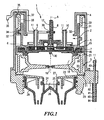
- the brewing device shown in Fig. 1 is part of a low-pressure coffee machine, which includes in known manner, not known here units such as water reservoir, boiler device, water pump and the required for the brewing and pumping electricity.
- a low-pressure coffee machine which includes in known manner, not known here units such as water reservoir, boiler device, water pump and the required for the brewing and pumping electricity.
- the upper Brühschteil 2 consists of an upper functional part 5, an inner valve unit 6 and a pressure plate 7.
- the upper functional part 5 is formed such that it covers the recorded in the pressure plate 7 valve unit 6 and the shift shaft 8 receives.
- a feed connection for brewing water 9 and a discharge connection for hot water 10 are further formed.
- a circumferential collar 11 is present at each of the open ends, which facilitates the connection and the attachment of the brewing water lines.
- the functional part 5 abuts against the pressure plate 7 and includes with its outer edge lateral lip seal 15, which is fixed in the outer region between the upper functional part 5 and the pressure plate 7 and partially protrudes in the axial direction down over the pressure plate 7.
- the pressure plate 7 has an annular circumferential, downwardly projecting web 16 in the axial direction, which projects as the only part of the pressure plate 7 down over the lip seal 15.
- a pin 30 is arranged, on which a laterally extending downwardly directed spring element for positioning and holding the coffee pad can be fastened.
- the pressure plate 7 of the upper Brühhuntteils 2 forms together with the removable cassette 8 a brewing chamber 18.
- the removable cassette 3 has a recess in the middle of the brewing chamber outlet 19 is located.
- the depression has a first shoulder 20 which fixes the coffee pad with the web 16 of the pressure plate 7.
- This paragraph 20 closes in shape a further paragraph on a projection 21 which cooperates with the recessed relative to the web 16 lip seal 15 to seal the brewing chamber 18.
- the rotating projection 21 simultaneously forms the upper edge of the removable cassette 3.
- the removable cassette 3 has on one side a handle, not shown, with which the removable cassette 3 can be pulled out of the brewing device 1 in the open position.
- the housing 4 on the side of the handle has a corresponding opening.
- the interchangeable cassette 3 can also be reversed in an inverted state, ie the top and bottom of the interchangeable cassette 3 are exchanged into the brewing device 1.
- the side shown in Fig. 1 as the underside of the removable cassette 3 has a smaller recess than the top, which can form a brewing chamber 18 with a reduced volume with this bottom.
- the shoulder 20 and the projection 21 are formed on the underside of the removable cassette 3 in the lateral region of the depression.
- the removable cassette 3 is supported on its underside with the outer shoulder 21 on the support plate 23, which laterally forms an extension of the housing 4 and is connected thereto.
- the support plate 23 has centrally a drain 26 with a drawn down splash guard 27. Below the splash guard is a sieve 24 with an underlying drain cone 25, which together provide a creamy coffee.
- the outlet 28 is screwed into a recess of the support plate 23, which is formed by the axially extending annular portion 29 of the section plate 23.
- the ring portion 29 is provided for receiving the spout 28 with an internal thread.
- the spout 28 directs the coffee two outlet spouts.
- a hot water outlet pipe 80 is arranged with a hot water channel 81.
- the hot water outlet pipe 80 merges into a projection 82, or is connected to this projection 82, which extends laterally from the support plate 23 and protrudes relative to the housing 4.
- the hot water channel 81 passes through the projection 82 and opens above the projection 82 side of the housing 4 in a hot water connection pipe 83 which is provided at the end with a collar 11 to facilitate the secure connection of a hot water line, not shown.
- the hot water spout 80 is provided with a decorated sleeve 84 which is slid onto the hot water spout 80.
- the upper functional part 5 is connected to an axially extending annular formed pressing member 31.
- a guide rib 32 is formed, which extends helically around the outer periphery of the pressing member 31.
- the guide bar 32 is divided into at least three repeating sections, resulting in the same number of points of attack for the transmission of the axial movement.
- the operating member 33 is further placed, which extends above the guide bar 32 to the upper edge of the housing.
- the likewise ring-shaped actuating part 33 is designed ramp-shaped and rotatably disposed about the pressing member 31.
- the actuating part is connected to a handle 36.
- the actuating part 33 further has a hook 34 which engages around the guide web 32.
- the guide web 32 further comprises a horizontal web portion, which is in the brewing position with the hook 34 of the actuating part 33 in connection, in order to forward the pressure forces arising during brewing in the vertical direction.
- the guide web 32 has a horizontal web portion, which is arranged at the lower end of the helical guide web 32 and serves as a stop of the lifting device for the open position of the brewing device 1.
- the handle 36 is additionally connected by means of the transmission bracket 37 with the switching shaft 8, wherein a circular portion-shaped opening 38 at the end of the transmission bracket 37 on the one side flattened end 12 of the shift shaft 8 sits, and thereby the operation of the shift shaft 8 directly with the rotation of the actuating member 33rd coupled by the handle 36.
- the valve unit 6 consists of the channel plate 40 and an upper membrane 41, which is arranged between the channel plate 40 and in the upper functional part 5, and a lower membrane 42, which is located between the channel plate 40 and the pressure plate 7.
- the upper membrane 41 has an inlet hole 43 and the channel plate 40 has an inlet bore 44.
- the inlet channel for brewing water of the inlet connection 9, the inlet hole 43 and the inlet bore 44 are arranged coaxially to each other, wherein the inlet hole 43 in the membrane 41 has a slightly larger cross-section than the inlet bore 44 and the inlet channel, even with a slightly staggered arrangement the inflow channel, the inlet hole 43 and the inlet bore 44 to allow a brewing water inlet guide without constriction.
- the inlet bore 44 of the channel plate 40 communicates with the distributor recess 45, which is arranged centrally on the upper side of the channel plate 40.
- the distributor depression 45 has in its edge region the outlet bore 46 with the outlet ring 47 projecting into the distributor depression 45 and the outlet bore 48 with the outlet ring 49 protruding into the distributor depression 45.
- the outlet bore 46 and the spout bore 48 extend from the top of the channel plate 40 to the bottom of the channel plate 40.
- the outlet recess 50 is centrally located, which communicates with the outlet bore 46 and at least one, here three outlet holes 51st in the lower membrane 42, which also communicate with at least one, here three outlet openings 52 in the pressure plate 7, in order to allow the introduction of the brewing water into the brewing chamber 18.
- the outlet bore 48 is connected via the outlet channel 53 with the throttle bore 54 in connection, which has an orifice 55 on the top of the channel plate 40, and opens via the outlet hole 56 in the upper membrane 41 in the outlet channel of the outlet port 10.
- the outlet channel, the outlet bore 56, the orifice 55 and throttle bore 54 are arranged coaxially with each other, wherein the outlet hole 56 opposite the throttle bore 54 and the outlet channel has a slightly larger diameter.
- the design of the switching shaft 8 is clearly shown in Fig. 2.
- the switching shaft 8 is rotatably supported by a centered bore 13 at the switching end 14 on a protruding from the upper functional part 5 shaft projection 57.
- the flattened end 12 opposite the switching end 14 has a much larger cross-section than the rest of the switching shaft 8 and is guided by a top functional part 5 projecting ring 58 and secured by means of the ring 58 formed locking elements 59 in position.
- the switching end 14 of the switching shaft 8 has in addition to the central bore 13 in the two switching end 14 axially offset from each other buttons 61, 62, which are matched to the actuation of the valve balls 17, 22, which is guided in two bores 60 in the upper functional part 5 and are arranged on the upper diaphragm 41 in the region of the distributor recess 45 above the outlet bore 46 and the outlet bore 48.
- the valve balls 17, 22 together with the upper rubber diaphragm 41, the distributor recess 45, the outlet bore 46 with outlet ring 47 and the outlet bore 48 with discharge ring 49, the distribution valve. Through the distribution valve can within the valve unit 6 is switched between the outlet of brewing water in the brewing chamber and the outlet of hot water.
- Fig. 3 shows a perspective view of the underside of the channel plate 40.
- the inlet bore 44 opens on the underside of the channel plate 40 in the overflow channel 63 which in turn ends in the overflow bore 64.
- a through-bore 65 is arranged, which is delimited by a pressure ridge 66, which in turn is surrounded by a passage recess 67 in the channel plate 40.
- the passage recess 67 opens via the distributor channel 68 in the distributor bore 69, which opens into the distributor depression 45 on the upper side of the channel plate 40.
- the overflow channel 63 with the overflow hole 64 and the inlet bore 44, the coniservertiefung 67 with the manifold 68 and the manifold bore 69, the outlet recess 50 with the outlet bore 46 and the outlet channel 53 with the outlet bore 48th and the throttle bore 54, are provided on the surface of the channel plate 40 with two juxtaposed ribs 70 which cooperate with a corresponding counter rib on the pressure plate 7 to effect in conjunction with the lower membrane 42 as large a sealing effect to each other and to the environment ,
- the arranged on the top of the channel plate 40 channel sections and through holes are provided in a corresponding manner with two circumferential ribs, which cooperate with a corresponding counter rib on the underside of the upper functional part 5.
- the channel plate 40 further comprises three recesses 71 arranged on the circumference of the channel plate and a plurality of positioning holes 73 in the channel plate 40 itself, which position the channel plate 40 with respect to the pressure plate 7.
- Through the positioning holes 72 extend from the pressure plate 7 more bolts into the upper functional part 5, whereby a total of a fixed positioning of the pressure plate 7, the lower diaphragm 42, the channel plate 40, the upper diaphragm 41 and the upper functional part 5 is ensured to each other .
- On the underside of the channel plate 40 a plurality of bolt portions 73 are further arranged, which protrude in the thickness of the lower membrane 42 from the lower surface of the channel plate 40 and in addition to the Positioning holes 72 and the recesses 71 support the arrangement of the lower membrane 42 on the underside of the channel plate 40 and also prevent local slippage, displacement, compression or stretching of the rubber-elastic membrane 42 substantially.
- the upper side of the channel plate 40 is also provided with corresponding bolt portions 73 in order to fix the upper di
- Fig. 4 shows a further section through the upper Brühhuntteil 2 along the line IV - IV shown in Fig. 3 Again, the arranged between the pressure plate 7 and the upper functional part 5 valve unit 6 of channel plate 40 and the upper and lower membrane 41, 42 shown.
- the distributor recess 45 can be seen in the center again, while on the underside the outlet recess 50 in connection with the outlet hole 51 in the lower membrane 42 and the outlet opening 52 laterally opening of the pin 30 into the brewing chamber 18 is further to see the overflow bore 64 extending from the underside of the channel plate 40 to the top, which communicates via the overflow channel 63 with the inlet bore 44 in connection.
- the overflow bore 64 spreads to the overflow recess 74.
- the upper membrane 41 has laterally offset to the overflow hole 64 an overflow hole 75 which is dimensioned by the diameter so that there is a pressureless flow of cold brewing water or the heating overflow from the Boiler just barely allows.
- an overflow bulge 76 is incorporated in the upper functional part 5, which extends substantially above the overflow recess 74 in the channel plate 40 and is formed with a concave curvature and a circular cross section. The overflow bulge 76 extends into the overflow channel of the overflow port 77.
- overflow channel, the overflow bulge 76 and the overflow bore 64, and preferably also the overflow groove 74 are aligned coaxially with each other, while the overflow hole 75 is arranged offset to the overflow bore 64 and the overflow channel of the overflow port 77.
- FIG. 5 also shows a cross section through the upper brewing chamber part, along the line V - V shown in FIG. 3.
- the valve unit 6, which is arranged between the upper functional part 5 and the pressure plate 7, is made up of the channel plate 40 and the upper and lower membrane 41. 42 shown. Centered on top of the channel plate 40 is the distribution well 45, while on the bottom of the outlet recess 50 with the outlet hole 51 in the lower membrane 42 and the outlet opening 52 in the pressure plate 7 is shown. Further, the through hole 65 extending from the top of the channel plate 40 to the bottom is to be seen with the pressure ring 66 projecting from the underside of the channel plate 40.
- the protruding pressure ring 66 causes a downwardly formed in the pressure plate 7 fürlaufwölbung 78 deflection of the lower membrane 42.
- Side of the pressure ring 66 and above the lower membrane 42 is located around the pressure ring 66 around the flow depression 67, which extends through the distribution channel 68th extends into the manifold bore 69.
- the resting on the support plate 23 removable cassette 3 are removed from the brewing device 1 to the to load selected depression of the removable cassette 3 with one or optionally two filter pads.
- the upper position is usually provided with two coffee pads, or a coffee pad with a double amount of ground coffee.
- the loaded removable cassette 3 is pushed back into the brewing device 1. After completion of the loading process, the brewing device is transferred with the handle 36 in the brewing position.
- the handle 36 is pivoted about the vertical axis A and the associated with him operating part 33 and the shift shaft 8 is rotated about this vertical axis A.
- the actuating member 33 presses with its ramp-shaped portion on the helical guide bar 32, wherein the contact between the actuating part 33 and the guide bar 32 decreases with increasing movement in the direction of the brewing position.
- the upper Brühschteil 2 is pressed in the vertical direction on the removable cassette 3.
- the annular circumferential, axially projecting from the pressure plate 7, web 16 touches the upper shoulder 20 of the removable cassette 3, wherein the lip seal 15 presses on the projection 21 further.
- the lower projection is pressed onto the launch plate 23.
- the position of the removable cassette 3 is aligned by the upper Brühschteil 2 during the closing operation.
- the brewing chamber 18 presses the pressure plate 7 with a pin 30 arranged on the spring element, the coffee pad evenly into the recess of the removable cassette 3. This creates between the coffee pad and the pressure plate 7 over a large area of the pressure plate 7 radially extending cavity.
- the brewing chamber 18 formed from the pressure plate 7 and the recess of the removable cassette 3 is sealed off from the environment by the web 16 pressing on the shoulder 20 and the lip seal 15 pressing on the projection 21.
- the connection between the distributor recess 45 and the outlet bore 48 is opened and, if necessary, brewing water can be removed from the outlet connection 10.
- the second valve ball 22 closes the spout bore 48 by the pressure of the axially projecting button 61 by the pressure of the upper diaphragm 41 on the spout 49, while the outlet bore 46 opposite the spreader recess 45 is open and allows for a promotion of the brewing water by a pump, the outlet of the brewing water through the outlet opening 52 into the brewing chamber 18 inside.
- buttons 61 and 62 are arranged to each other so that the outlet hole 46 is opened only in the moment in which the lip seal 15 contacts the upper projection 21 during the closing movement and ensures a seal of the brewing chamber 18 from the environment.
- the brewing water can only flow into the brewing chamber 18 when the brewing chamber 18 is sealed. This prevents that in an insufficiently closed brewing chamber 18, the brewing water can leak from this, because the seal the lip seal 15 to the upper projection 21 of the removable cassette 3 is not sure yet.
- the brewing water is heated in a boiler device.
- heated brewing water is fed through the inlet port 9 in the valve unit 6.
- the heated brewing water replaces the previously existing in these lines air, condensate and / or cooled brewing water pressure-free through the overflow valve and the overflow port 77 are led out of the upper Brühhuntteil 2.
- a portion of the already heated brewing water is also conveyed out of the upper brewing chamber part 2 via the overflow valve and the overflow connection 77. Characterized the valve unit 6 and the surrounding elements of the upper Brühhuntteils 2 is heated.
- the expansion of the brewing water in the boiler device is so small and uniform that a flow velocity or a pressure forms in the overflow valve which is insufficient to press the upper membrane 41 into the concave overflow bulge 76 and by the membrane contacting the wall the overflow bulge 76 to close the overflow hole 75 in the membrane 41.
- the overflow connection 77 remains open and no pressure can build up in the valve unit 6.
- a small stream of the heated brewing water is passed over the valve unit 6 which, upon cooling the brewing water from a water reservoir is tracked in the boiler device, whereby the valve unit 6 does not cool completely in a stand-by mode and in the valve unit 6 constantly heated brewing water ready for the preparation of coffee.
- the overflow valve allows the drain of condensate and cooled brewing water both in the brewing position of the brewing device 1, as well as in the position for tapping hot water.
- the overflow valve closes due to the increased pressure in the valve unit 6.
- the upper diaphragm 41 is pressed against the wall of the overflow bulge 76 in the upper functional part 5, whereby the overflow hole 75 is sealed in the membrane 41.
- the overflow recess 74 formed in the channel plate 40 is responsible not only for the supply of water to the overflow hole 75 at an open overflow valve, but also for the formation of a sufficient pressure on the membrane 41 and a uniform distribution of this pressure in a pressurized Condition to ensure a secure concern of the membrane on the wall of the overflow buckle 76 and thus a secure closing of the overflow valve.
- the flow valve When pressure rises in the valve unit 6, the flow valve opens from the through-bore 65, the upper pressure ring 66, the lower diaphragm 42, the fürlaufauswölbung 78 and the fürlaufverianaung 67. In the unpressurized state, the flow valve is closed because the rubber membrane 42 by the clamping between the pressure plate 7 and the channel plate 40 firmly on the opposite the underside of the channel plate 40 projecting pressure ring 66 is pressed.
- the membrane 42 When caused by the pump pressure increase in the valve unit 6, the membrane 42 is pressed down into the fürlaufsvölbung 78, thereby opening between the pressure ring 66 and the rubber membrane 42, a gap through which the brewing water in the flow depression 67 and from there via the distribution channel 68 and the distributor bore 69 can flow into the distributor recess 45.
- one or two filter pads are arranged in the brewing chamber 18.
- a circumferential locking edge of the upper filter pad rests on the top of the upper paragraph 20 and is therefore in the brewing position between the shoulder 20 and the web 16.
- hot brewing water is supplied via the inlet connection 9 of the valve unit 6 after the initiation of the brewing process by the pump. Since the overflow valve is already closed by the increase in pressure, the brewing water flows through the open flow valve into the distributor recess 45 and from there via the brewing water outlet into the brewing chamber.
- the coffee pad is first moistened by the water and flows through the brewing water in the further course, which emerges from the brewing chamber 18 as coffee at the brewing chamber outlet 19 and impinges on the wire 24 via the drain 26. It must be ensured that the coffee, which strikes the screen 24 as a thin spray jet, is immediately removed via the distributor cone 25. This refinement forms a fine crema. After a certain, adjustable period of time, or a subsidized amount of water, the pump is switched off again, thus completing the brewing process. When the pressure drops, the overflow valve opens first, reducing the pressure quickly and closing the flow valve abruptly.
- the brewing chamber 18 can be opened again by pivoting back the handle 36.
- the upper Brühschteil 2 is moved in the axial direction upwards, because the guide bar 32 is encompassed by the hook 34.
- the hook 34 transmits the induced by the rotational movement of the actuating member 32 axial movement in the direction of the open position on the guide bar 32 on the pressing member 31 and thus on the upper Brühhuntteil 2.
- opening the brewing chamber 18 can be arranged on a pin 30 spring element on the wet coffee pad Press and solve after the brewing on the pressure plate 7 adhering areas of the coffee pad, the coffee pad remains when opening the brewing device in the recess of the removable cassette 3 and is not moved together with the upper part of the brewing chamber upwards.
- the pressure plate 7 is moved so far up that the web 16 is above the opening for the removable cassette 3 in the housing.
- the removable cassette 3 can be pulled out of the brewing device together with the spent, moistened by the brewing water coffee pad.
- the removable cassette 3 can be re-provided for a further brewing process with a coffee pad, or pushed back unfilled in the brewing device.
- an orifice 55 is arranged, which builds up a pressure due to their flow resistance during the removal of hot water in the valve unit 6, which ensures a secure closing of the overflow valve as in the brewing process.
- the diameter of the orifice 55 is preferably adjusted so that the pump can be operated at the same operating point both during the brewing process and during the tapping of hot water. In this way, both coffee and hot water can be provided in a comparable amount with the same setting of the electronic control.
- the outlet port 10 for hot water at the upper Brühschteil 2 is connected by means of a plastic tube with the hot water outlet pipe 80 which is arranged laterally on the brewing device and connected by the projection 82 with the support plate 23.
Landscapes
- Engineering & Computer Science (AREA)
- Mechanical Engineering (AREA)
- Food Science & Technology (AREA)
- Apparatus For Making Beverages (AREA)
- Alcoholic Beverages (AREA)
- Micro-Organisms Or Cultivation Processes Thereof (AREA)
- Cookers (AREA)
Claims (22)
- Dispositif d'infusion pour préparer du café, en particulier pour une machine à café basse pression, comprenant une chambre d'infusion (18) et une unité d'amenée pour l'eau d'infusion qui comporte une amenée (9) et une sortie pour l'eau d'infusion ainsi qu'une unité de soupape (6) pourvue d'au moins une membrane (41) et d'une plaque à conduits (40), la plaque à conduits (40) présentant au moins une ouverture de soupape sur sa face reliée à la membrane (41), au moins une partie de conduit qui est reliée à ladite ouverture de soupape et qui est destinée à guider l'eau d'infusion dans la plaque à conduits (40), et au moins un perçage de passage qui est relié à ladite partie de conduit et qui débouche sur la face opposée de la plaque (40),
caractérisé en ce que la ou les membranes (41) présentent au moins un trou qui permet à l'eau d'infusion de passer d'une face de la membrane à l'autre. - Dispositif d'infusion selon la revendication 1, caractérisé en ce que la ou les membranes (41) sont conçues comme des plaques flexibles d'une seule pièce, de préférence en caoutchouc, qui s'étendent globalement sur une surface frontale de la plaque à conduits (40).
- Dispositif d'infusion selon la revendication 1 ou 2, caractérisé en ce que l'unité d'amenée présente une sortie d'eau chaude (10) et l'unité de soupape (6) comprend une soupape d'écoulement d'eau chaude.
- Dispositif d'infusion selon la revendication 3, caractérisé en ce que la sortie d'eau chaude (10) présente un orifice d'étranglement (55).
- Dispositif d'infusion selon la revendication 3 ou 4, caractérisé en ce que la soupape d'écoulement est formée par la plaque à conduits (40) et la ou les membranes (41), un perçage d'écoulement (48) étant formé dans ladite plaque (40) de manière à pouvoir être obturé par la membrane (41).
- Dispositif d'infusion selon l'une des revendications 1 à 5, caractérisé en ce que l'unité de soupape (6) comprend une soupape d'écoulement.
- Dispositif d'infusion selon la revendication 6, caractérisé en ce que la soupape de sortie est formée par la plaque à conduits (40) et la ou les membranes (41), un perçage de sortie (46) étant formé dans ladite plaque (40) de manière à pouvoir être obturé par la membrane (41).
- Dispositif d'infusion selon l'une des revendications 3 à 7, caractérisé en ce qu'il est prévu un mécanisme de positionnement, ce mécanisme de positionnement étant conçu pour faire passer l'unité de soupape (6) de la sortie prévue pour l'eau d'infusion à la sortie d'eau chaude (10) et inversement.
- Dispositif d'infusion selon la revendication 8, caractérisé en ce que le mécanisme de positionnement comprend deux corps de soupape, de préférence deux billes de soupape (17, 22), et ces corps de soupape sont aptes à obturer le perçage de sortie (46) et le perçage d'écoulement d'eau chaude (48) à l'aide de la membrane (41).
- Dispositif d'infusion selon la revendication 9, caractérisé en ce que le mécanisme de positionnement comprend par ailleurs un axe de commande rotatif (8) avec un contour à cames qui présente différentes surfaces de commande (61, 62) décalées axialement, les surfaces de commande (61, 62) étant définies par les positions de positionnement et de détente associées aux deux corps de soupape, et l'axe de commande (8), dans les positions de positionnement et de détente associées, poussant les corps de soupape sur la membrane (41) ou les déchargeant à l'aide desdites surfaces de commande (61, 62) décalées axialement, et la membrane (41) obturant ou dégageant les perçages de sortie et d'écoulement d'eau chaude (46, 48).
- Dispositif d'infusion selon l'une des revendications 1 à 10, caractérisé en ce que l'unité d'amenée comporte un trop-plein pour l'eau d'infusion (77) et l'unité de soupape (6) comprend une soupape de trop-plein.
- Dispositif d'infusion selon la revendication 11, caractérisé en ce que la soupape de trop-plein comprend par ailleurs un élément fonctionnel de l'unité d'amenée, et la soupape de trop-plein est formée par la plaque à conduits (40), la ou les membranes (41) et l'élément fonctionnel, la membrane (41) présentant un trou (75) qui est apte à être obturé par la plaque à conduits (40) ou l'élément fonctionnel.
- Dispositif d'infusion selon l'une des revendications 1 à 12, caractérisé en ce que la plaque à conduits (40) est en matière plastique et est de préférence conçue comme une pièce moulée par injection.
- Dispositif d'infusion selon l'une des revendications 1 à 13, caractérisé en ce que la plaque à conduits (40) présente des perçages (72) et/ou des creux (71) pour son positionnement dans l'unité d'amenée.
- Dispositif d'infusion selon l'une des revendications 1 à 14, caractérisé en ce que la plaque à conduits (40) présente sur au moins une face frontale des parties de tiges saillantes (73) pour la fixation de ladite membrane (41).
- Dispositif d'infusion selon l'une des revendications 10 à 15, caractérisé en ce qu'il est prévu une bague d'actionnement (33) pour l'ouverture de la chambre d'infusion (18), et de préférence une poignée (36) pour l'actionnement de ladite bague (33), la bague d'actionnement (33) et/ou la poignée (36) étant conçues pour actionner le mécanisme de positionnement.
- Dispositif d'infusion selon l'une des revendications 1 à 16, caractérisé en ce que l'unité de soupape (6) comprend une seconde membrane (42).
- Dispositif d'infusion selon la revendication 17, caractérisé en ce que la seconde membrane (42) est conçue comme une plaque flexible d'une seule pièce, de préférence en caoutchouc, qui s'étend globalement sur une seconde surface frontale de la plaque à conduits (40).
- Dispositif d'infusion selon la revendication 17 ou 18, caractérisé en ce que la seconde membrane (42) présente des trous qui permettent à l'eau d'infusion de passer d'une face de la membrane à l'autre.
- Dispositif d'infusion selon l'une des revendications 7 à 19, caractérisé en ce que l'unité de soupape (6) comprend une soupape de pression, la soupape de pression permettant l'amenée d'eau d'infusion sous pression dans la soupape de sortie et/ou dans la soupape d'écoulement d'eau chaude.
- Dispositif d'infusion selon la revendication 20, caractérisé en ce que la soupape de pression est formée par la plaque à conduits (40) et la seconde membrane (42), un perçage de passage étant formé dans la plaque à conduits (40) de manière à pouvoir être obturé par la membrane (42).
- Dispositif d'infusion selon l'une des revendications 1 à 21, caractérisé en ce que la chambre d'infusion (18) comporte une partie supérieure (2), une partie inférieure et au moins un sachet-filtre qui est disposé dans une cavité de la partie de chambre d'infusion inférieure et qui est rempli de café moulu, les parties de chambre d'infusion supérieure (2) et inférieure étant mobiles l'une par rapport à l'autre et étant aptes à passer d'une position d'ouverture dans laquelle la dosette de café peut être mise en place ou enlevée à une position d'infusion, et l'unité d'amenée étant disposée dans la partie de chambre supérieure (2).
Priority Applications (1)
| Application Number | Priority Date | Filing Date | Title |
|---|---|---|---|
| PL05020605T PL1639922T3 (pl) | 2004-09-22 | 2005-09-21 | Urządzenie do zaparzania z odpływem gorącej wody |
Applications Claiming Priority (1)
| Application Number | Priority Date | Filing Date | Title |
|---|---|---|---|
| DE202004014738U DE202004014738U1 (de) | 2004-09-22 | 2004-09-22 | Brühvorrichtung mit Heißwasserauslauf |
Publications (3)
| Publication Number | Publication Date |
|---|---|
| EP1639922A2 EP1639922A2 (fr) | 2006-03-29 |
| EP1639922A3 EP1639922A3 (fr) | 2006-05-24 |
| EP1639922B1 true EP1639922B1 (fr) | 2007-12-12 |
Family
ID=35462354
Family Applications (1)
| Application Number | Title | Priority Date | Filing Date |
|---|---|---|---|
| EP05020605A Expired - Lifetime EP1639922B1 (fr) | 2004-09-22 | 2005-09-21 | Dispositif d'infusion avec sortie d'eau chaude |
Country Status (4)
| Country | Link |
|---|---|
| EP (1) | EP1639922B1 (fr) |
| AT (1) | ATE380491T1 (fr) |
| DE (2) | DE202004014738U1 (fr) |
| PL (1) | PL1639922T3 (fr) |
Families Citing this family (3)
| Publication number | Priority date | Publication date | Assignee | Title |
|---|---|---|---|---|
| US7861645B2 (en) | 2005-10-14 | 2011-01-04 | Electrical And Electronics Limited | Apparatus for preventing unintended or premature release of liquid in a beverage brewing device and method thereof |
| DE102005055182B4 (de) * | 2005-11-18 | 2015-05-21 | BSH Hausgeräte GmbH | Partikelsieb für Pad-Kaffeemaschinen |
| DE102013203656B4 (de) * | 2013-03-04 | 2016-03-03 | Robert Bosch Gmbh | Mikrofluidisches Drehventil |
Family Cites Families (4)
| Publication number | Priority date | Publication date | Assignee | Title |
|---|---|---|---|---|
| GB939183A (en) | 1960-01-21 | 1963-10-09 | Atomic Energy Authority Uk | Improvements in or relating to nuclear fuel elements |
| CZ294409B6 (cs) * | 1993-12-20 | 2004-12-15 | Compagnie Mediterraneenne Des Cafes (S. A.) | Automat pro přípravu horkých spařovaných nápojů |
| IT1310366B1 (it) * | 1999-05-04 | 2002-02-13 | Euromatik Srl | Dispositivo di alimentazione di cialde monodose precompresse nellemacchine per la produzione di bevande di caffe' espresso. |
| ITTO20010404A1 (it) | 2001-04-27 | 2002-10-27 | Pres Block Spa | Valvola di tipo perfezionato. |
-
2004
- 2004-09-22 DE DE202004014738U patent/DE202004014738U1/de not_active Expired - Lifetime
-
2005
- 2005-09-21 PL PL05020605T patent/PL1639922T3/pl unknown
- 2005-09-21 DE DE502005002202T patent/DE502005002202D1/de not_active Expired - Lifetime
- 2005-09-21 AT AT05020605T patent/ATE380491T1/de active
- 2005-09-21 EP EP05020605A patent/EP1639922B1/fr not_active Expired - Lifetime
Also Published As
| Publication number | Publication date |
|---|---|
| PL1639922T3 (pl) | 2008-04-30 |
| EP1639922A3 (fr) | 2006-05-24 |
| ATE380491T1 (de) | 2007-12-15 |
| DE502005002202D1 (de) | 2008-01-24 |
| DE202004014738U1 (de) | 2006-02-09 |
| EP1639922A2 (fr) | 2006-03-29 |
Similar Documents
| Publication | Publication Date | Title |
|---|---|---|
| EP0588987B1 (fr) | Machine pour preparation d'une boisson | |
| EP0662297B1 (fr) | Dispositif pour produire du lait moussé pour cappuccino | |
| EP0544690B1 (fr) | Machine a cafe express | |
| EP2545826B1 (fr) | Machine à café expresso avec unité d'infusion | |
| DE10334542A1 (de) | Brühvorrichtung mit elastischem Element zum Niederhalten des Kaffeepads | |
| EP3654809B1 (fr) | Procédé pour commander manuellement une unité de commande de distribution de vapeur dans une machine à café et unité de commande correspondante | |
| EP1944089A2 (fr) | Pomme de douche ayant plusieurs zones fonctionnelles | |
| EP1690482B1 (fr) | Dispositif d'infusion avec soupape de surpression | |
| EP1639922B1 (fr) | Dispositif d'infusion avec sortie d'eau chaude | |
| EP2062512B1 (fr) | Machine à café dotée d'un dispositif de ventilation | |
| EP1440645B1 (fr) | Machine à café | |
| DE69904029T2 (de) | Dampfbügeleisen | |
| DE2346707A1 (de) | Mischventil fuer warmes und kaltes wasser | |
| DE60303888T2 (de) | Kaffeemaschine | |
| EP0111969B1 (fr) | Dispositif de filtrage | |
| EP1502530B1 (fr) | Mécanisme de vanne pour un dispositif d'infusion | |
| DE4431435A1 (de) | Einhebelmischventil | |
| DE602005002216T2 (de) | Dampfspendevorrichtung für die Zubereitung von heissen und/oder aufgeschäumten Getränken | |
| EP3643843B1 (fr) | Cartouche de commutation pour connecter une voie d'eau dans une armature, une douchette ou une pomme de douche | |
| EP0927580B1 (fr) | Pomme de douche | |
| DE3942969C2 (fr) | ||
| DE2657355A1 (de) | Brueheinrichtung fuer kaffeemaschinen | |
| DE3742203A1 (de) | Vorrichtung zum zubereiten von cappuccino | |
| DE60120626T2 (de) | Espressomaschine mit einem abwassersystem für das heizelement | |
| EP0194431B1 (fr) | Dispositif d'injection de carburant à haute pression pour moteur à combustion interne |
Legal Events
| Date | Code | Title | Description |
|---|---|---|---|
| PUAI | Public reference made under article 153(3) epc to a published international application that has entered the european phase |
Free format text: ORIGINAL CODE: 0009012 |
|
| AK | Designated contracting states |
Kind code of ref document: A2 Designated state(s): AT BE BG CH CY CZ DE DK EE ES FI FR GB GR HU IE IS IT LI LT LU LV MC NL PL PT RO SE SI SK TR |
|
| AX | Request for extension of the european patent |
Extension state: AL BA HR MK YU |
|
| PUAL | Search report despatched |
Free format text: ORIGINAL CODE: 0009013 |
|
| AK | Designated contracting states |
Kind code of ref document: A3 Designated state(s): AT BE BG CH CY CZ DE DK EE ES FI FR GB GR HU IE IS IT LI LT LU LV MC NL PL PT RO SE SI SK TR |
|
| AX | Request for extension of the european patent |
Extension state: AL BA HR MK YU |
|
| 17P | Request for examination filed |
Effective date: 20060724 |
|
| RIN1 | Information on inventor provided before grant (corrected) |
Inventor name: DIE ERFINDER HABEN AUF IHRE NENNUNG VERZICHTET. |
|
| AKX | Designation fees paid |
Designated state(s): AT BE BG CH CY CZ DE DK EE ES FI FR GB GR HU IE IS IT LI LT LU LV MC NL PL PT RO SE SI SK TR |
|
| GRAP | Despatch of communication of intention to grant a patent |
Free format text: ORIGINAL CODE: EPIDOSNIGR1 |
|
| 111Z | Information provided on other rights and legal means of execution |
Free format text: ATBEBGCHCYCZDEDKEEESFIFRGBGRHUIEISITLTLULVMCNLPLPTROSESISKTR Effective date: 20070710 |
|
| GRAS | Grant fee paid |
Free format text: ORIGINAL CODE: EPIDOSNIGR3 |
|
| GRAA | (expected) grant |
Free format text: ORIGINAL CODE: 0009210 |
|
| AK | Designated contracting states |
Kind code of ref document: B1 Designated state(s): AT BE BG CH CY CZ DE DK EE ES FI FR GB GR HU IE IS IT LI LT LU LV MC NL PL PT RO SE SI SK TR |
|
| REG | Reference to a national code |
Ref country code: GB Ref legal event code: FG4D Free format text: NOT ENGLISH |
|
| REG | Reference to a national code |
Ref country code: CH Ref legal event code: NV Representative=s name: ISLER & PEDRAZZINI AG Ref country code: CH Ref legal event code: EP |
|
| GBT | Gb: translation of ep patent filed (gb section 77(6)(a)/1977) |
Effective date: 20071212 |
|
| REG | Reference to a national code |
Ref country code: IE Ref legal event code: FG4D Free format text: LANGUAGE OF EP DOCUMENT: GERMAN |
|
| REF | Corresponds to: |
Ref document number: 502005002202 Country of ref document: DE Date of ref document: 20080124 Kind code of ref document: P |
|
| PG25 | Lapsed in a contracting state [announced via postgrant information from national office to epo] |
Ref country code: SE Free format text: LAPSE BECAUSE OF FAILURE TO SUBMIT A TRANSLATION OF THE DESCRIPTION OR TO PAY THE FEE WITHIN THE PRESCRIBED TIME-LIMIT Effective date: 20080312 |
|
| REG | Reference to a national code |
Ref country code: PL Ref legal event code: T3 |
|
| PG25 | Lapsed in a contracting state [announced via postgrant information from national office to epo] |
Ref country code: LV Free format text: LAPSE BECAUSE OF FAILURE TO SUBMIT A TRANSLATION OF THE DESCRIPTION OR TO PAY THE FEE WITHIN THE PRESCRIBED TIME-LIMIT Effective date: 20071212 Ref country code: SI Free format text: LAPSE BECAUSE OF FAILURE TO SUBMIT A TRANSLATION OF THE DESCRIPTION OR TO PAY THE FEE WITHIN THE PRESCRIBED TIME-LIMIT Effective date: 20071212 Ref country code: LT Free format text: LAPSE BECAUSE OF FAILURE TO SUBMIT A TRANSLATION OF THE DESCRIPTION OR TO PAY THE FEE WITHIN THE PRESCRIBED TIME-LIMIT Effective date: 20071212 Ref country code: FI Free format text: LAPSE BECAUSE OF FAILURE TO SUBMIT A TRANSLATION OF THE DESCRIPTION OR TO PAY THE FEE WITHIN THE PRESCRIBED TIME-LIMIT Effective date: 20071212 |
|
| ET | Fr: translation filed | ||
| PG25 | Lapsed in a contracting state [announced via postgrant information from national office to epo] |
Ref country code: CZ Free format text: LAPSE BECAUSE OF FAILURE TO SUBMIT A TRANSLATION OF THE DESCRIPTION OR TO PAY THE FEE WITHIN THE PRESCRIBED TIME-LIMIT Effective date: 20071212 Ref country code: ES Free format text: LAPSE BECAUSE OF FAILURE TO SUBMIT A TRANSLATION OF THE DESCRIPTION OR TO PAY THE FEE WITHIN THE PRESCRIBED TIME-LIMIT Effective date: 20080323 Ref country code: IS Free format text: LAPSE BECAUSE OF FAILURE TO SUBMIT A TRANSLATION OF THE DESCRIPTION OR TO PAY THE FEE WITHIN THE PRESCRIBED TIME-LIMIT Effective date: 20080412 |
|
| PG25 | Lapsed in a contracting state [announced via postgrant information from national office to epo] |
Ref country code: SK Free format text: LAPSE BECAUSE OF FAILURE TO SUBMIT A TRANSLATION OF THE DESCRIPTION OR TO PAY THE FEE WITHIN THE PRESCRIBED TIME-LIMIT Effective date: 20071212 Ref country code: RO Free format text: LAPSE BECAUSE OF FAILURE TO SUBMIT A TRANSLATION OF THE DESCRIPTION OR TO PAY THE FEE WITHIN THE PRESCRIBED TIME-LIMIT Effective date: 20071212 |
|
| PG25 | Lapsed in a contracting state [announced via postgrant information from national office to epo] |
Ref country code: PT Free format text: LAPSE BECAUSE OF FAILURE TO SUBMIT A TRANSLATION OF THE DESCRIPTION OR TO PAY THE FEE WITHIN THE PRESCRIBED TIME-LIMIT Effective date: 20080512 |
|
| REG | Reference to a national code |
Ref country code: IE Ref legal event code: FD4D |
|
| PLBE | No opposition filed within time limit |
Free format text: ORIGINAL CODE: 0009261 |
|
| STAA | Information on the status of an ep patent application or granted ep patent |
Free format text: STATUS: NO OPPOSITION FILED WITHIN TIME LIMIT |
|
| PG25 | Lapsed in a contracting state [announced via postgrant information from national office to epo] |
Ref country code: DK Free format text: LAPSE BECAUSE OF FAILURE TO SUBMIT A TRANSLATION OF THE DESCRIPTION OR TO PAY THE FEE WITHIN THE PRESCRIBED TIME-LIMIT Effective date: 20071212 Ref country code: IE Free format text: LAPSE BECAUSE OF FAILURE TO SUBMIT A TRANSLATION OF THE DESCRIPTION OR TO PAY THE FEE WITHIN THE PRESCRIBED TIME-LIMIT Effective date: 20071212 |
|
| 26N | No opposition filed |
Effective date: 20080915 |
|
| PG25 | Lapsed in a contracting state [announced via postgrant information from national office to epo] |
Ref country code: MC Free format text: LAPSE BECAUSE OF NON-PAYMENT OF DUE FEES Effective date: 20080930 Ref country code: EE Free format text: LAPSE BECAUSE OF FAILURE TO SUBMIT A TRANSLATION OF THE DESCRIPTION OR TO PAY THE FEE WITHIN THE PRESCRIBED TIME-LIMIT Effective date: 20071212 Ref country code: BG Free format text: LAPSE BECAUSE OF FAILURE TO SUBMIT A TRANSLATION OF THE DESCRIPTION OR TO PAY THE FEE WITHIN THE PRESCRIBED TIME-LIMIT Effective date: 20080312 |
|
| PG25 | Lapsed in a contracting state [announced via postgrant information from national office to epo] |
Ref country code: CY Free format text: LAPSE BECAUSE OF FAILURE TO SUBMIT A TRANSLATION OF THE DESCRIPTION OR TO PAY THE FEE WITHIN THE PRESCRIBED TIME-LIMIT Effective date: 20071212 |
|
| PG25 | Lapsed in a contracting state [announced via postgrant information from national office to epo] |
Ref country code: HU Free format text: LAPSE BECAUSE OF FAILURE TO SUBMIT A TRANSLATION OF THE DESCRIPTION OR TO PAY THE FEE WITHIN THE PRESCRIBED TIME-LIMIT Effective date: 20080613 Ref country code: LU Free format text: LAPSE BECAUSE OF NON-PAYMENT OF DUE FEES Effective date: 20080921 |
|
| PG25 | Lapsed in a contracting state [announced via postgrant information from national office to epo] |
Ref country code: TR Free format text: LAPSE BECAUSE OF FAILURE TO SUBMIT A TRANSLATION OF THE DESCRIPTION OR TO PAY THE FEE WITHIN THE PRESCRIBED TIME-LIMIT Effective date: 20071212 |
|
| PG25 | Lapsed in a contracting state [announced via postgrant information from national office to epo] |
Ref country code: IT Free format text: LAPSE BECAUSE OF NON-PAYMENT OF DUE FEES Effective date: 20080930 |
|
| PG25 | Lapsed in a contracting state [announced via postgrant information from national office to epo] |
Ref country code: GR Free format text: LAPSE BECAUSE OF NON-PAYMENT OF DUE FEES Effective date: 20080930 |
|
| REG | Reference to a national code |
Ref country code: DE Ref legal event code: R082 Ref document number: 502005002202 Country of ref document: DE Representative=s name: GRUENECKER, KINKELDEY, STOCKMAIR & SCHWANHAEUS, DE |
|
| REG | Reference to a national code |
Ref country code: DE Ref legal event code: R081 Ref document number: 502005002202 Country of ref document: DE Owner name: WMF WUERTTEMBERGISCHE METALLWARENFABRIK AKTIEN, DE Free format text: FORMER OWNER: PAV PATENTVERWERTUNG KG, 83395 FREILASSING, DE Effective date: 20121004 Ref country code: DE Ref legal event code: R082 Ref document number: 502005002202 Country of ref document: DE Representative=s name: GRUENECKER, KINKELDEY, STOCKMAIR & SCHWANHAEUS, DE Effective date: 20121004 Ref country code: DE Ref legal event code: R081 Ref document number: 502005002202 Country of ref document: DE Owner name: WMF AG, DE Free format text: FORMER OWNER: PAV PATENTVERWERTUNG KG, 83395 FREILASSING, DE Effective date: 20121004 Ref country code: DE Ref legal event code: R082 Ref document number: 502005002202 Country of ref document: DE Representative=s name: GRUENECKER PATENT- UND RECHTSANWAELTE PARTG MB, DE Effective date: 20121004 Ref country code: DE Ref legal event code: R081 Ref document number: 502005002202 Country of ref document: DE Owner name: WMF GROUP GMBH, DE Free format text: FORMER OWNER: PAV PATENTVERWERTUNG KG, 83395 FREILASSING, DE Effective date: 20121004 |
|
| REG | Reference to a national code |
Ref country code: CH Ref legal event code: PUE Owner name: WMF WUERTTEMBERGISCHE METALLWARENFABRIK AG, DE Free format text: FORMER OWNER: PAV PATENTVERWERTUNG KG, DE |
|
| REG | Reference to a national code |
Ref country code: NL Ref legal event code: SD Effective date: 20130920 |
|
| REG | Reference to a national code |
Ref country code: FR Ref legal event code: TP Owner name: WMF WURTTEMBERGISCHE METALLWARENFABRIK AKTIENG, DE Effective date: 20130926 |
|
| PGFP | Annual fee paid to national office [announced via postgrant information from national office to epo] |
Ref country code: NL Payment date: 20130920 Year of fee payment: 9 Ref country code: AT Payment date: 20130919 Year of fee payment: 9 Ref country code: CH Payment date: 20130923 Year of fee payment: 9 |
|
| REG | Reference to a national code |
Ref country code: GB Ref legal event code: 732E Free format text: REGISTERED BETWEEN 20131010 AND 20131016 |
|
| PGFP | Annual fee paid to national office [announced via postgrant information from national office to epo] |
Ref country code: GB Payment date: 20130920 Year of fee payment: 9 Ref country code: PL Payment date: 20130920 Year of fee payment: 9 |
|
| PGFP | Annual fee paid to national office [announced via postgrant information from national office to epo] |
Ref country code: FR Payment date: 20130918 Year of fee payment: 9 Ref country code: BE Payment date: 20130919 Year of fee payment: 9 |
|
| REG | Reference to a national code |
Ref country code: DE Ref legal event code: R082 Ref document number: 502005002202 Country of ref document: DE Representative=s name: GRUENECKER, KINKELDEY, STOCKMAIR & SCHWANHAEUS, DE |
|
| REG | Reference to a national code |
Ref country code: AT Ref legal event code: PC Ref document number: 380491 Country of ref document: AT Kind code of ref document: T Owner name: WMF WUERTTEMBERGISCHE METALLWARENFABRIK AKTIEN, DE Effective date: 20140303 |
|
| REG | Reference to a national code |
Ref country code: DE Ref legal event code: R081 Ref document number: 502005002202 Country of ref document: DE Owner name: WMF AG, DE Free format text: FORMER OWNER: WMF WUERTTEMBERGISCHE METALLWARENFABRIK AKTIENGESELLSCHAFT, 73312 GEISLINGEN, DE Effective date: 20140310 Ref country code: DE Ref legal event code: R082 Ref document number: 502005002202 Country of ref document: DE Representative=s name: GRUENECKER, KINKELDEY, STOCKMAIR & SCHWANHAEUS, DE Effective date: 20140310 Ref country code: DE Ref legal event code: R082 Ref document number: 502005002202 Country of ref document: DE Representative=s name: GRUENECKER PATENT- UND RECHTSANWAELTE PARTG MB, DE Effective date: 20140310 Ref country code: DE Ref legal event code: R081 Ref document number: 502005002202 Country of ref document: DE Owner name: WMF GROUP GMBH, DE Free format text: FORMER OWNER: WMF WUERTTEMBERGISCHE METALLWARENFABRIK AKTIENGESELLSCHAFT, 73312 GEISLINGEN, DE Effective date: 20140310 |
|
| REG | Reference to a national code |
Ref country code: CH Ref legal event code: PL |
|
| REG | Reference to a national code |
Ref country code: AT Ref legal event code: MM01 Ref document number: 380491 Country of ref document: AT Kind code of ref document: T Effective date: 20140921 |
|
| GBPC | Gb: european patent ceased through non-payment of renewal fee |
Effective date: 20140921 |
|
| REG | Reference to a national code |
Ref country code: FR Ref legal event code: ST Effective date: 20150529 |
|
| PG25 | Lapsed in a contracting state [announced via postgrant information from national office to epo] |
Ref country code: BE Free format text: LAPSE BECAUSE OF NON-PAYMENT OF DUE FEES Effective date: 20140930 Ref country code: NL Free format text: LAPSE BECAUSE OF NON-PAYMENT OF DUE FEES Effective date: 20150401 |
|
| PG25 | Lapsed in a contracting state [announced via postgrant information from national office to epo] |
Ref country code: GB Free format text: LAPSE BECAUSE OF NON-PAYMENT OF DUE FEES Effective date: 20140921 Ref country code: CH Free format text: LAPSE BECAUSE OF NON-PAYMENT OF DUE FEES Effective date: 20140930 Ref country code: LI Free format text: LAPSE BECAUSE OF NON-PAYMENT OF DUE FEES Effective date: 20140930 |
|
| PG25 | Lapsed in a contracting state [announced via postgrant information from national office to epo] |
Ref country code: FR Free format text: LAPSE BECAUSE OF NON-PAYMENT OF DUE FEES Effective date: 20140930 Ref country code: AT Free format text: LAPSE BECAUSE OF NON-PAYMENT OF DUE FEES Effective date: 20140921 |
|
| PG25 | Lapsed in a contracting state [announced via postgrant information from national office to epo] |
Ref country code: PL Free format text: LAPSE BECAUSE OF NON-PAYMENT OF DUE FEES Effective date: 20140921 |
|
| REG | Reference to a national code |
Ref country code: DE Ref legal event code: R082 Ref document number: 502005002202 Country of ref document: DE Representative=s name: GRUENECKER PATENT- UND RECHTSANWAELTE PARTG MB, DE Ref country code: DE Ref legal event code: R081 Ref document number: 502005002202 Country of ref document: DE Owner name: WMF GROUP GMBH, DE Free format text: FORMER OWNER: WMF AG, 73312 GEISLINGEN, DE |
|
| PGFP | Annual fee paid to national office [announced via postgrant information from national office to epo] |
Ref country code: DE Payment date: 20180924 Year of fee payment: 14 |
|
| REG | Reference to a national code |
Ref country code: DE Ref legal event code: R119 Ref document number: 502005002202 Country of ref document: DE |
|
| PG25 | Lapsed in a contracting state [announced via postgrant information from national office to epo] |
Ref country code: DE Free format text: LAPSE BECAUSE OF NON-PAYMENT OF DUE FEES Effective date: 20200401 |