EP1639239B1 - Method and device for estimating a nitrogen oxide mass stored in a catalytic trapping device of a motor vehicle - Google Patents
Method and device for estimating a nitrogen oxide mass stored in a catalytic trapping device of a motor vehicle Download PDFInfo
- Publication number
- EP1639239B1 EP1639239B1 EP04767463A EP04767463A EP1639239B1 EP 1639239 B1 EP1639239 B1 EP 1639239B1 EP 04767463 A EP04767463 A EP 04767463A EP 04767463 A EP04767463 A EP 04767463A EP 1639239 B1 EP1639239 B1 EP 1639239B1
- Authority
- EP
- European Patent Office
- Prior art keywords
- catalytic
- nitrogen oxides
- mass
- reactor
- trap
- Prior art date
- Legal status (The legal status is an assumption and is not a legal conclusion. Google has not performed a legal analysis and makes no representation as to the accuracy of the status listed.)
- Not-in-force
Links
Images

Classifications
-
- F—MECHANICAL ENGINEERING; LIGHTING; HEATING; WEAPONS; BLASTING
- F01—MACHINES OR ENGINES IN GENERAL; ENGINE PLANTS IN GENERAL; STEAM ENGINES
- F01N—GAS-FLOW SILENCERS OR EXHAUST APPARATUS FOR MACHINES OR ENGINES IN GENERAL; GAS-FLOW SILENCERS OR EXHAUST APPARATUS FOR INTERNAL COMBUSTION ENGINES
- F01N3/00—Exhaust or silencing apparatus having means for purifying, rendering innocuous, or otherwise treating exhaust
- F01N3/08—Exhaust or silencing apparatus having means for purifying, rendering innocuous, or otherwise treating exhaust for rendering innocuous
- F01N3/0807—Exhaust or silencing apparatus having means for purifying, rendering innocuous, or otherwise treating exhaust for rendering innocuous by using absorbents or adsorbents
- F01N3/0871—Regulation of absorbents or adsorbents, e.g. purging
-
- F—MECHANICAL ENGINEERING; LIGHTING; HEATING; WEAPONS; BLASTING
- F01—MACHINES OR ENGINES IN GENERAL; ENGINE PLANTS IN GENERAL; STEAM ENGINES
- F01N—GAS-FLOW SILENCERS OR EXHAUST APPARATUS FOR MACHINES OR ENGINES IN GENERAL; GAS-FLOW SILENCERS OR EXHAUST APPARATUS FOR INTERNAL COMBUSTION ENGINES
- F01N9/00—Electrical control of exhaust gas treating apparatus
- F01N9/005—Electrical control of exhaust gas treating apparatus using models instead of sensors to determine operating characteristics of exhaust systems, e.g. calculating catalyst temperature instead of measuring it directly
-
- F—MECHANICAL ENGINEERING; LIGHTING; HEATING; WEAPONS; BLASTING
- F02—COMBUSTION ENGINES; HOT-GAS OR COMBUSTION-PRODUCT ENGINE PLANTS
- F02D—CONTROLLING COMBUSTION ENGINES
- F02D41/00—Electrical control of supply of combustible mixture or its constituents
- F02D41/02—Circuit arrangements for generating control signals
- F02D41/021—Introducing corrections for particular conditions exterior to the engine
- F02D41/0235—Introducing corrections for particular conditions exterior to the engine in relation with the state of the exhaust gas treating apparatus
- F02D41/027—Introducing corrections for particular conditions exterior to the engine in relation with the state of the exhaust gas treating apparatus to purge or regenerate the exhaust gas treating apparatus
- F02D41/0275—Introducing corrections for particular conditions exterior to the engine in relation with the state of the exhaust gas treating apparatus to purge or regenerate the exhaust gas treating apparatus the exhaust gas treating apparatus being a NOx trap or adsorbent
-
- F—MECHANICAL ENGINEERING; LIGHTING; HEATING; WEAPONS; BLASTING
- F01—MACHINES OR ENGINES IN GENERAL; ENGINE PLANTS IN GENERAL; STEAM ENGINES
- F01N—GAS-FLOW SILENCERS OR EXHAUST APPARATUS FOR MACHINES OR ENGINES IN GENERAL; GAS-FLOW SILENCERS OR EXHAUST APPARATUS FOR INTERNAL COMBUSTION ENGINES
- F01N2570/00—Exhaust treating apparatus eliminating, absorbing or adsorbing specific elements or compounds
- F01N2570/14—Nitrogen oxides
-
- F—MECHANICAL ENGINEERING; LIGHTING; HEATING; WEAPONS; BLASTING
- F02—COMBUSTION ENGINES; HOT-GAS OR COMBUSTION-PRODUCT ENGINE PLANTS
- F02D—CONTROLLING COMBUSTION ENGINES
- F02D2200/00—Input parameters for engine control
- F02D2200/02—Input parameters for engine control the parameters being related to the engine
- F02D2200/08—Exhaust gas treatment apparatus parameters
- F02D2200/0806—NOx storage amount, i.e. amount of NOx stored on NOx trap
-
- F—MECHANICAL ENGINEERING; LIGHTING; HEATING; WEAPONS; BLASTING
- F02—COMBUSTION ENGINES; HOT-GAS OR COMBUSTION-PRODUCT ENGINE PLANTS
- F02D—CONTROLLING COMBUSTION ENGINES
- F02D2200/00—Input parameters for engine control
- F02D2200/02—Input parameters for engine control the parameters being related to the engine
- F02D2200/08—Exhaust gas treatment apparatus parameters
- F02D2200/0811—NOx storage efficiency
-
- Y—GENERAL TAGGING OF NEW TECHNOLOGICAL DEVELOPMENTS; GENERAL TAGGING OF CROSS-SECTIONAL TECHNOLOGIES SPANNING OVER SEVERAL SECTIONS OF THE IPC; TECHNICAL SUBJECTS COVERED BY FORMER USPC CROSS-REFERENCE ART COLLECTIONS [XRACs] AND DIGESTS
- Y02—TECHNOLOGIES OR APPLICATIONS FOR MITIGATION OR ADAPTATION AGAINST CLIMATE CHANGE
- Y02A—TECHNOLOGIES FOR ADAPTATION TO CLIMATE CHANGE
- Y02A50/00—TECHNOLOGIES FOR ADAPTATION TO CLIMATE CHANGE in human health protection, e.g. against extreme weather
- Y02A50/20—Air quality improvement or preservation, e.g. vehicle emission control or emission reduction by using catalytic converters
-
- Y—GENERAL TAGGING OF NEW TECHNOLOGICAL DEVELOPMENTS; GENERAL TAGGING OF CROSS-SECTIONAL TECHNOLOGIES SPANNING OVER SEVERAL SECTIONS OF THE IPC; TECHNICAL SUBJECTS COVERED BY FORMER USPC CROSS-REFERENCE ART COLLECTIONS [XRACs] AND DIGESTS
- Y02—TECHNOLOGIES OR APPLICATIONS FOR MITIGATION OR ADAPTATION AGAINST CLIMATE CHANGE
- Y02T—CLIMATE CHANGE MITIGATION TECHNOLOGIES RELATED TO TRANSPORTATION
- Y02T10/00—Road transport of goods or passengers
- Y02T10/10—Internal combustion engine [ICE] based vehicles
- Y02T10/12—Improving ICE efficiencies
-
- Y—GENERAL TAGGING OF NEW TECHNOLOGICAL DEVELOPMENTS; GENERAL TAGGING OF CROSS-SECTIONAL TECHNOLOGIES SPANNING OVER SEVERAL SECTIONS OF THE IPC; TECHNICAL SUBJECTS COVERED BY FORMER USPC CROSS-REFERENCE ART COLLECTIONS [XRACs] AND DIGESTS
- Y02—TECHNOLOGIES OR APPLICATIONS FOR MITIGATION OR ADAPTATION AGAINST CLIMATE CHANGE
- Y02T—CLIMATE CHANGE MITIGATION TECHNOLOGIES RELATED TO TRANSPORTATION
- Y02T10/00—Road transport of goods or passengers
- Y02T10/10—Internal combustion engine [ICE] based vehicles
- Y02T10/40—Engine management systems
Definitions
- the present invention relates to a method and a system for estimating a mass of nitrogen oxides stored in a device for catalytic trapping of nitrogen oxides traversed by the exhaust gases of an internal combustion engine of motor vehicle.
- the estimation of the mass of nitrogen oxides stored in such a catalytic trapping device is particularly useful for managing the regeneration of the catalytic trapping device, by supplying the engine with a fuel-rich mixture during a fuel phase. regeneration of said device.
- the document WO 01/00972 describes such a device.
- a catalytic trapping device can be arranged in the exhaust line of the engine.
- the catalytic trapping device operates in a discontinuous manner, that is to say in nominal operation in a fuel-poor mixture, the catalytic device traps the nitrogen oxides, but does not not treat.
- the engine must operate in fuel-rich mixture for a short regeneration period of the device, so that the unburned hydrocarbons and carbon monoxide then emitted in large quantities reduce the nitrogen oxides stored.
- the patent DE 199 07 382 relates to estimating the temperature of a nitrogen oxide trapping device from the temperature of the gases upstream of the trapping device. However, it is not used to estimate the amounts of adsorbed nitrogen oxides, storage and purge efficiencies.
- the aim of the invention is, in the light of the foregoing, to propose a solution that makes it possible to estimate the mass of nitrogen oxides stored in a catalytic nitrogen oxide trap device, in a more precise way than in known methods.
- the method according to the invention makes it possible to estimate a mass of nitrogen oxides stored in a device for catalytic trapping of nitrogen oxides, comprising a catalytic phase, through which the exhaust gases of a combustion engine internal vehicle, comprising an electronic control unit.
- the geometry of the catalytic trapping device is discretized into several (n) successive individual reactors perfectly agitated.
- a thermal model is combined, making it possible to calculate the variation of the temperature of the catalytic phase of the catalytic trapping device during the passage of the exhaust gases, and an adsorption model making it possible to calculate the mass at any time. of nitrogen oxides stored in the catalytic trapping device according to the characteristics of the catalytic trapping device, the temperatures resulting from the thermal model for each individual reactor, and the mass flow rate of the engine exhaust gas.
- the adsorption properties of nitrogen oxides of the catalytic phase are very strongly related to the temperature of the adsorption sites.
- the combination of an adsorption model based on the thermal state of the catalytic phase to a thermal model makes it possible to improve the estimates efficiently.
- Said storage capacity is a function of corrective parameters comprising the hourly volume velocity of the individual reactor i, the aging of the catalytic trapping device, and its sulfur poisoning.
- the geometry of the catalytic trapping device is discretized into a number of successive perfectly stirred individual reactors of between 1 and 6.
- the device comprises means for effecting a correction on the storage capacity of the catalytic trapping device (1) of nitrogen oxides of each individual reactor i of rank i.
- Said correction is a predetermined function of the inlet temperature of the individual reactor i
- said storage capacity is a function of corrective parameters comprising the hourly volume velocity of the individual reactor i, the aging of the catalytic trapping device, and its poisoning at sulfur.
- a particularly advantageous application of the invention consists in periodically regenerating a device for catalytic trapping of nitrogen oxides through which the exhaust gases of a lean-burn internal combustion engine of a motor vehicle comprise an electronic control unit.
- the mass of nitrogen oxides trapped in the catalytic trapping device is estimated by means of the method according to the invention, or with a device according to the invention, which will be an input data of a device for managing the regeneration phases of the catalytic device.
- FIG. 1 there is shown the general architecture of a system for estimating a mass of nitrogen oxides stored in a catalytic trapping device 1 of nitrogen oxides crossed by exhaust gases 2 of a internal combustion engine 3 of a motor vehicle 4, supplied with a lean fuel mixture, comprising an electronic control unit 5.
- the electronic control unit 5 is connected with the catalytic trapping device 1, and with the engine 3.
- the engine 3 rejects exhaust gases in the exhaust line 2. These exhaust gases pass through the catalytic trapping device 1 which will store a part of the nitrogen oxides contained in the exhaust gas. These gases are then released into the atmosphere.
- the electronic calculation unit is connected to control means of the engine 3 making it possible to operate the engine 3 in a fuel-rich mixture as a means of regeneration of the catalytic trapping device 1.
- the figure 2 represents a perfectly stirred individual reactor of rank i belonging to the discretization of the catalytic trapping device 1 in n perfectly stirred individual reactors, for an adsorption model, according to the invention.
- a thermal model is described which makes it possible to calculate, from certain input data, the outlet temperature on a reactor. individual.
- This model also uses a discretization of the catalytic device in individual reactors, independent of the discretization of the adsorption model.
- This thermal model makes it possible to calculate the outlet temperature of an individual reactor of rank k of the thermal model corresponding to the inlet of an individual reactor of rank i of the adsorption model.
- the individual k-rank reactor of the thermal model is chosen so that its outlet temperature is that of the rank i reactor of the adsorption model, in other words so that a part of the catalytic phase of these two individual reactors is common.
- the said thermal model taken as an example uses the mass flow rate Qg of the exhaust gases, the value of which is fed to the inlet 8 of the reactor 7, the temperature T_k -1 arriving at the inlet 9 of said individual reactor 7 of rank k-1.
- the temperature measured under the engine hood and brought to the inlet 10, the speed of the vehicle brought to the inlet 11, and the concentrations of the substances contained in the exhaust gas at the inlet of the catalytic trapping device 1 are brought to the input 12.
- the thermal model makes it possible to calculate the output temperature T_k 13 of the individual reactor 7 of rank k-1, which serves as input temperature T_i of the individual reactor 6 of rank i for the adsorption model, the value of T_k equal to T_i being brought by the connection 13.
- the adsorption model uses, at the inlet of an individual reactor 6 of rank i of said adsorption model, the inlet temperature T_i, fed to the inlet 13, the mass flow rate NOx_i of nitrogen oxides fed to the inlet 14, a corrective factor such as the hourly space velocity VVH_i on the inlet 15, and any other corrections, such as the aging of the catalytic trapping device 1 or the nive
- the thermal aging of the catalytic trapping device results in an irreversible reduction in the specific exchange surface area accessible to the gases. Thermal aging thus impacts the adsorption of oxides of nitrogen and the reduction of these nitrogen oxides during the regeneration phases of the device.
- a block 17 then calculates the maximum mass, NSC_i of nitrogen oxides being able to be stored by the reactor i 6, at the output 18 of the block 17.
- a block 19 calculates the NS_i / NSC_i ratio of nitrogen oxides of the individual reactor 6 of rank i at the outlet 20 of the block 19, as well as the mass NS_i of nitrogen oxides present in the reactor i 6 at the outlet 21 of the block 19.
- the block 19 performs these calculations by means of the input 18 NSC_i, and the input 22 represents the quantity of nitrogen oxides adsorbed instantaneously dNS_i / dt by the reactor i 6.
- the quantity of oxides of The adsorption model comprises a looping of the ratio NS_i / NSC_i nitrogen oxides of the individual reactor 6 of rank i of block 19 on the block 23, which is adsorbed instantaneously dNS_i / dt by the reactor. by the connection 20.
- the mass NSC_i of the individual reactor 6 of rank i is a predetermined function of T_i.
- the block 23 also calculates, at the outlet 24, the efficiency Eff_i of instantaneous storage of nitrogen oxides in the individual reactor 6 of rank i, as a predetermined function of the ratio NS_i / NSC_i and T_i.
- a block 25 then calculates the mass flow rate of nitrogen oxides NOx_i + 1 at the outlet 26 of the individual reactor 6 of rank i, which will be the mass flow rate at the inlet of the reactor of rank i + 1.
- This calculation carried out by the block 25 by means of the formula (1-Eff_i) * NOx_i, which takes as input the efficiency Eff_i of storage instantaneous nitrogen oxides and mass flow NOx_i of nitrogen oxides.
- the adsorption model makes it possible to calculate the mass flow rate of nitrogen oxides NOx_i + 1 at outlet 26 of the individual reactor 6 of rank i, which will be an input of the adsorption model for the individual reactor of rank i + 1.
- the NOx_1 value of the mass flow rate of nitrogen oxides at the inlet of the first reactor and the hourly volume velocity VVH_i are calculated using known or measured models.
- the quantity of nitrogen oxides instantly adsorbed by the individual reactor 6 of rank i dNS_i / dt is calculated using the product NOx_i * Eff_i.
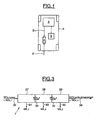
- the figure 3 represents a device discretized according to the invention, in three successive individual reactors perfectly agitated, namely the reactor 27 of rank 1, the reactor 28 of rank 2, and the reactor 29 of rank 3.
- Each reactor of rank i behaves like that is explained in the figure 2 .
- the mass of nitrogen oxides NS_2, at outlet 33, stored in the second reactor 28, and the mass flow rate of nitrogen oxides NOx_3 at the outlet 34 of the second reactor 28 are calculated, and inlet 34 of the third reactor 29.
- the mass of nitrogen oxides NS_3, at the outlet 35, stored in the third reactor 29, and the mass flow rate of NOx_4 nitrogen oxides at the outlet 36 of the third reactor 29 are calculated.
- the invention makes it possible to estimate the mass of nitrogen oxides trapped in the catalytic trapping device precisely, while simultaneously taking into account a thermal model and an adsorption model in the catalytic trapping device.
- the invention also makes it possible to accurately estimate the mass flow rate of nitrogen oxides at the outlet of the catalytic trapping device.
- the invention also makes it possible to control the regeneration of the catalytic trapping device by operating the fuel-rich mixture engine for a predetermined short time, based on the estimate of the mass of nitrogen oxides stored in the device. catalytic trapping, and its comparison with a predetermined value.
Abstract
Description
La présente invention concerne un procédé et un système d'estimation d'une masse d'oxydes d'azote stockée dans un dispositif de piégeage catalytique d'oxydes d'azote traversé par les gaz d'échappement d'un moteur à combustion interne de véhicule automobile.The present invention relates to a method and a system for estimating a mass of nitrogen oxides stored in a device for catalytic trapping of nitrogen oxides traversed by the exhaust gases of an internal combustion engine of motor vehicle.
L'estimation de la masse d'oxydes d'azote stockée dans un tel dispositif de piégeage catalytique est notamment utile pour gérer la régénération du dispositif de piégeage catalytique, en alimentant le moteur avec un mélange plus riche en carburant lors d'une phase de régénération dudit dispositif. Le document
En effet, afin de répondre à la baisse des seuils admis pour les émissions de gaz polluants des véhicules automobiles, un dispositif de piégeage catalytique peut être disposé dans la ligne d'échappement du moteur. Contrairement à un catalyseur d'oxydation traditionnel, le dispositif de piégeage catalytique fonctionne de façon discontinue, c'est-à-dire qu'en fonctionnement nominal en mélange pauvre en carburant, le dispositif catalytique piège les oxydes d'azote, mais ne les traite pas. Pour régénérer le dispositif de piégeage catalytique, le moteur doit fonctionner en mélange riche en carburant pendant une courte période de régénération du dispositif, afin que les hydrocarbures imbrûlés et les monoxydes de carbone alors émis en grande quantité réduisent les oxydes d'azote stockés.Indeed, in order to meet the lower thresholds for emissions of gaseous pollutants from motor vehicles, a catalytic trapping device can be arranged in the exhaust line of the engine. In contrast to a conventional oxidation catalyst, the catalytic trapping device operates in a discontinuous manner, that is to say in nominal operation in a fuel-poor mixture, the catalytic device traps the nitrogen oxides, but does not not treat. To regenerate the catalytic trapping device, the engine must operate in fuel-rich mixture for a short regeneration period of the device, so that the unburned hydrocarbons and carbon monoxide then emitted in large quantities reduce the nitrogen oxides stored.
Pour optimiser le traitement de l'ensemble des polluants, il est nécessaire de gérer au mieux les phases de stockage et de régénération du piège. Il est notamment nécessaire d'estimer au cours du temps la quantité d'oxydes d'azote stockée, ou du moins l'efficacité de stockage en oxydes d'azote du dispositif de piégeage, pendant le fonctionnement nominal du moteur en mélange pauvre en carburant.To optimize the treatment of all pollutants, it is necessary to better manage the storage and regeneration phases of the trap. In particular, it is necessary to estimate, over time, the quantity of nitrogen oxides stored, or at least the nitrogen oxide storage efficiency of the trapping device, during the nominal operation of the fuel-lean engine. .
Le brevet
L'invention a pour but, au vu de ce qui précède, de proposer une solution qui permette d'estimer la masse d'oxydes d'azote stockée dans un dispositif de piégeage catalytique d'oxydes d'azote, de manière plus précise que dans les méthodes connues.The aim of the invention is, in the light of the foregoing, to propose a solution that makes it possible to estimate the mass of nitrogen oxides stored in a catalytic nitrogen oxide trap device, in a more precise way than in known methods.
Le procédé selon l'invention permet d'estimer une masse d'oxydes d'azote stockée dans un dispositif de piégeage catalytique d'oxydes d'azote, comprenant une phase catalytique, traversé par les gaz d'échappement d'un moteur à combustion interne de véhicule automobile, comportant une unité de contrôle électronique. Dans ce procédé, on discrétise la géométrie du dispositif de piégeage catalytique en plusieurs (n) réacteurs individuels successifs parfaitement agités. De plus, on combine un modèle thermique, permettant de calculer la variation de la température de la phase catalytique du dispositif de piégeage catalytique lors de la traversée des gaz d'échappement, et un modèle d'adsorption permettant de calculer à tout instant la masse d'oxydes d'azote stockée dans le dispositif de piégeage catalytique en fonction des caractéristiques du dispositif de piégeage catalytique, des températures issues du modèle thermique pour chaque réacteur individuel, et du débit massique de gaz d'échappement du moteur.The method according to the invention makes it possible to estimate a mass of nitrogen oxides stored in a device for catalytic trapping of nitrogen oxides, comprising a catalytic phase, through which the exhaust gases of a combustion engine internal vehicle, comprising an electronic control unit. In this process, the geometry of the catalytic trapping device is discretized into several (n) successive individual reactors perfectly agitated. In addition, a thermal model is combined, making it possible to calculate the variation of the temperature of the catalytic phase of the catalytic trapping device during the passage of the exhaust gases, and an adsorption model making it possible to calculate the mass at any time. of nitrogen oxides stored in the catalytic trapping device according to the characteristics of the catalytic trapping device, the temperatures resulting from the thermal model for each individual reactor, and the mass flow rate of the engine exhaust gas.
Les propriétés d'adsorption d'oxydes d'azote de la phase catalytique sont très fortement liées à la température des sites d'adsorption. La combinaison d'un modèle d'adsorption se basant sur l'état thermique de la phase catalytique à un modèle thermique permet d'améliorer efficacement les estimations.The adsorption properties of nitrogen oxides of the catalytic phase are very strongly related to the temperature of the adsorption sites. The combination of an adsorption model based on the thermal state of the catalytic phase to a thermal model makes it possible to improve the estimates efficiently.
Dans un mode de mise en oeuvre préféré, on effectue une correction sur la capacité de stockage du dispositif de piégeage catalytique en oxydes d'azote de chaque réacteur individuel i de rang i (i=1 à n) étant une fonction prédéterminée de la température de la phase catalytique du réacteur individuel i. Ladite capacité de stockage est une fonction de paramètres correctifs comprenant la vitesse volumique horaire du réacteur individuel i, le vieillissement du dispositif de piégeage catalytique, et son empoisonnement au soufre.In a preferred embodiment, a correction is made to the storage capacity of the catalytic nitrogen oxide trap device of each individual reactor i of rank i (i = 1 to n) being a predetermined function of the temperature. of the catalytic phase of the individual reactor i. Said storage capacity is a function of corrective parameters comprising the hourly volume velocity of the individual reactor i, the aging of the catalytic trapping device, and its sulfur poisoning.
Dans un mode de mise en oeuvre avantageux, on calcule la masse d'oxydes d'azote adsorbée instantanément (dNS_i/dt) par le dispositif de piégeage catalytique de chaque réacteur individuel i (i=1 à n) au moyen de la relation suivante : ![]()
dans laquelle :
- NOx_i :
- débit massique d'oxydes d'azote en entrée du réacteur individuel i, en g/s, NOx_1 calculé ;
- Eff_i :
- efficacité de stockage instantanée dans le réacteur individuel i, fonction prédéterminée de NS_i/NSC_i et de T_i, obtenue par bouclage du calcul de NS_i/NSC_i ;
- NS_i:
- masse d'oxydes d'azote présente dans le réacteur i , en g ;
- NSC_i :
- masse maximale d'oxydes d'azote pouvant être stockée par le réacteur i, en g
- T_i:
- température de la phase catalytique en entrée du réacteur individuel i, calculée par le modèle thermique, en K.
in which :
- NOx_i:
- mass flow rate of nitrogen oxides at the inlet of the individual reactor i, in g / s, NOx_1 calculated;
- Eff_i:
- instantaneous storage efficiency in the individual reactor i, a predetermined function of NS_i / NSC_i and T_i, obtained by looping the calculation of NS_i / NSC_i;
- NS_i:
- mass of nitrogen oxides present in the reactor i, in g;
- NSC_i:
- maximum mass of nitrogen oxides that can be stored by reactor i, in g
- t_i:
- temperature of the catalytic phase at the inlet of the individual reactor i, calculated by the thermal model, in K.
Dans un mode de mise en oeuvre préféré, on calcule la masse d'oxydes d'azote (NS_i) présente dans le réacteur individuel i depuis la fin de la dernière phase de régénération du dispositif de piégeage catalytique au moyen de la relation suivante : 
dans laquelle :
- intervalle t0 à t :
- intervalle de temps entre la fin (t0) de la dernière phase de régénération du dispositif de piégeage catalytique et l'instant présent (t), en s ; et
- NS_i :
- masse d'oxydes d'azote présente dans le réacteur i , en g.
- NS_i(t0):
- masse estimée d'oxydes d'azote présente dans le réacteur i à l'instant t0 correspondant à la fin de la dernière phase de régénération du dispositif catalytique (1), en g.
in which :
- interval t0 to t:
- time interval between the end (t 0 ) of the last regeneration phase of the catalytic trapping device and the instant present (t), in s; and
- NS_i:
- mass of nitrogen oxides present in the reactor i, in g.
- NS_i (t 0 ):
- estimated mass of nitrogen oxides present in the reactor i at time t0 corresponding to the end of the last regeneration phase of the catalytic device (1), in g.
Dans un mode de mise en oeuvre avantageux, on calcule la masse totale (NS) d'oxydes d'azote stockée dans l'ensemble du dispositif de piégeage catalytique au moyen de la relation suivante : ![]()
dans laquelle :
- NS :
- masse totale d'oxydes d'azote stockée dans l'ensemble du dispositif de piégeage catalytique, en g ; et
- NS_i :
- masse d'oxydes d'azote présente dans le réacteur individuel i, en g.
in which :
- NS:
- total mass of nitrogen oxides stored in the entire catalytic trapping device, in g; and
- NS_i:
- mass of nitrogen oxides present in the individual reactor i, in g.
Dans un mode de mise en oeuvre préféré, on calcule le débit d'oxydes d'azote non traités quittant le dernier réacteur n, au moyen de la relation suivante : ![]()
dans laquelle :
- NOx_sortie échappement :
- débit massique d'oxydes d'azote non traités, en sortie d'échappement après traversée du dispositif de piégeage catalytique, en g/s ;
- NOx_n :
- débit massique d'oxydes d'azote en entrée du dernier réacteur n, en g/s ; et
- Eff_n :
- efficacité de stockage instantanée dans le dernier réacteur n.
in which :
- Exhaust NOx:
- mass flow rate of untreated nitrogen oxides, at the exhaust outlet after passing through the catalytic trapping device, in g / s;
- NOx_n:
- mass flow rate of nitrogen oxides at the inlet of the last reactor n, in g / s; and
- Eff_n:
- instantaneous storage efficiency in the last reactor n.
Dans un mode de mise en oeuvre avantageux, on discrétise la géométrie du dispositif de piégeage catalytique en un nombre de réacteurs individuels successifs parfaitement agités compris entre 1 et 6.In an advantageous embodiment, the geometry of the catalytic trapping device is discretized into a number of successive perfectly stirred individual reactors of between 1 and 6.
Le dispositif selon l'invention permet d'estimer d'une masse d'oxydes d'azote stockée dans un dispositif de piégeage catalytique d'oxydes d'azote, comprenant une phase catalytique, et traversé par les gaz d'échappement d'un moteur à combustion interne de véhicule automobile, comportant une unité de contrôle électronique. Le dispositif comprend en outre :
- des moyens pour discrétiser la géométrie du dispositif de piégeage catalytique en plusieurs (n) réacteurs individuels successifs parfaitement agités ; et
- des moyens pour estimer la masse d'oxydes d'azote présente dans le dispositif de piégeage catalytique en combinant un modèle thermique permettant de calculer la variation de la température de la phase catalytique du dispositif de piégeage catalytique (1) lors de la traversée des gaz d'échappement, et un modèle d'adsorption permettant de calculer à tout instant la masse d'oxydes d'azote stockée dans le dispositif de piégeage catalytique (1) en fonction des caractéristiques du dispositif de piégeage catalytique (1), des températures issues du modèle thermique pour chaque réacteur individuel, et du débit massique de gaz d'échappement du moteur (3).
- means for discretizing the geometry of the catalytic trapping device into several (n) successive individual reactors perfectly agitated; and
- means for estimating the mass of nitrogen oxides present in the catalytic trapping device by combining a thermal model making it possible to calculate the variation of the temperature of the catalytic phase of the catalytic trapping device (1) during the crossing of the gases exhaust, and an adsorption model for calculating at any time the mass of nitrogen oxides stored in the catalytic trapping device (1) according to the characteristics of the catalytic trapping device (1), temperatures from the thermal model for each individual reactor, and the mass flow rate of the engine exhaust gas (3).
Dans un mode de réalisation préféré, le dispositif comprend des moyens pour effectuer une correction sur la capacité de stockage du dispositif de piégeage catalytique (1) en oxydes d'azote de chaque réacteur individuel i de rang i. Ladite correction est une fonction prédéterminée de la température d'entrée du réacteur individuel i, et ladite capacité de stockage est une fonction de paramètres correctifs comprenant la vitesse volumique horaire du réacteur individuel i, le vieillissement du dispositif de piégeage catalytique, et son empoisonnement au soufre.In a preferred embodiment, the device comprises means for effecting a correction on the storage capacity of the catalytic trapping device (1) of nitrogen oxides of each individual reactor i of rank i. Said correction is a predetermined function of the inlet temperature of the individual reactor i, and said storage capacity is a function of corrective parameters comprising the hourly volume velocity of the individual reactor i, the aging of the catalytic trapping device, and its poisoning at sulfur.
Une application particulièrement intéressante de l'invention consiste à régénérer périodiquement un dispositif de piégeage catalytique d'oxydes d'azote traversé par les gaz d'échappement d'un moteur à combustion interne à mélange pauvre de véhicule automobile comportant une unité de contrôle électronique. On estime la masse d'oxydes d'azote piégée dans le dispositif de piégeage catalytique au moyen du procédé selon l'invention, ou avec un dispositif selon l'invention, qui sera une donnée d'entrée d'un dispositif de gestion des phases de régénération du dispositif catalytique.A particularly advantageous application of the invention consists in periodically regenerating a device for catalytic trapping of nitrogen oxides through which the exhaust gases of a lean-burn internal combustion engine of a motor vehicle comprise an electronic control unit. The mass of nitrogen oxides trapped in the catalytic trapping device is estimated by means of the method according to the invention, or with a device according to the invention, which will be an input data of a device for managing the regeneration phases of the catalytic device.
D'autres buts, caractéristiques et avantages de l'invention apparaîtront à la lecture de la description suivante, donnée uniquement à titre d'exemple nullement limitatif, et faite en référence aux dessins annexés sur lesquels :
- la
figure 1 est un schéma synoptique d'un dispositif selon l'invention ; - la
figure 2 est un diagramme illustrant un réacteur individuel selon l'invention ; et - la
figure 3 est un diagramme illustrant un dispositif discrétisé selon l'invention.
- the
figure 1 is a block diagram of a device according to the invention; - the
figure 2 is a diagram illustrating an individual reactor according to the invention; and - the
figure 3 is a diagram illustrating a discretized device according to the invention.
Sur la
Le moteur 3 rejette des gaz d'échappement dans la ligne d'échappement 2. Ces gaz d'échappement traversent le dispositif de piégeage catalytique 1 qui va stocker une partie des oxydes d'azote contenus dans les gaz d'échappement. Ces gaz sont ensuite rejetés dans l'atmosphère. L'unité électronique de calcul est reliée à des moyens de commande du moteur 3 permettant de faire fonctionner le moteur 3 en mélange riche en carburant comme moyen de régénération du dispositif de piégeage catalytique 1.The
La
En entrée du réacteur individuel 7 de rang k du modèle thermique, ledit modèle thermique pris à titre d'exemple utilise le débit massique Qg des gaz d'échappement, dont la valeur est amenée sur l'entrée 8 du réacteur 7, la température T_k-1 arrivant sur l'entrée 9 dudit réacteur individuel 7 de rang k-1. La température Text mesurée sous le capot moteur et amenée à l'entrée 10, la vitesse du véhicule amenée sur l'entrée 11, et les concentrations des substances contenues dans les gaz d'échappement en entrée du dispositif de piégeage catalytique 1 sont amenées sur l'entrée 12. Le modèle thermique permet de calculer la température T_k de sortie 13 du réacteur individuel 7 de rang k-1, qui sert de température d'entrée T_i du réacteur individuel 6 de rang i pour le modèle d'adsorption, la valeur de T_k égale à T_i étant amenée par la connexion 13. Le modèle d'adsorption utilise, en entrée d'un réacteur individuel 6 de rang i dudit modèle d'adsorption, la température en entrée T_i, amenée sur l'entrée 13, le débit massique NOx_i d'oxydes d'azote amené sur l'entrée 14, un facteur correctif comme la vitesse volumique horaire VVH_i sur l'entrée 15, et d'éventuelles autres corrections, comme le vieillissement du dispositif de piégeage catalytique 1 ou le niveau d'empoisonnement au soufre sur l'entrée 16. En effet, le vieillissement thermique du dispositif de piégeage catalytique se traduit par une diminution irréversible de la surface spécifique d'échange accessible aux gaz. Le vieillissement thermique impacte donc l'adsorption des oxydes d'azote ainsi que la réduction de ces oxydes d'azote lors des phases de régénération du dispositif. des modifications irréversibles de la phase active en contact avec les gaz d'échappement, comme le frittage des métaux précieux, et de modifications irréversibles de la structure poreuse à base d'alumine, comme le frittage de l'alumine. De plus, la phase catalytique est sensible à l'empoisonnement par le soufre, car les oxydes de soufre Sox, entrant en compétition avec les oxydes d'azote NOx, viennent se fixer sur les sites actifs de la phase catalytique. Ces oxydes de soufre ne sont pas réduits ou désorbés lors des phases de régénération des NOx, il faut effectuer une régénération spécifique par désorption thermique en présence de réducteurs. Un bloc 17 calcule alors la masse maximale, NSC_i d'oxydes d'azote pouvant être stockée par le réacteur i 6, en sortie 18 du bloc 17. Cette masse maximale NSC_i dépend notamment de la température dans le réacteur de rang i, et de la vitesse volumique horaire et la composition du gaz. Un bloc 19 calcule le rapport NS_i/NSC_i en oxydes d'azotes du réacteur individuel 6 de rang i en sortie 20 du bloc 19, ainsi que la masse NS_i d'oxydes d'azote présente dans le réacteur i 6 en sortie 21 du bloc 19. Le bloc 19 effectue ces calculs au moyen de l'entrée 18 NSC_i, et de l'entrée 22 représentant la quantité d'oxydes d'azote adsorbée instantanément dNS_i/dt par le réacteur i 6. La quantité d'oxydes d'azote adsorbée instantanément dNS_i/dt par le réacteur i 6 est calculée par un bloc 23. Le modèle d'adsorption comprend un bouclage du rapport NS_i/NSC_i en oxydes d'azotes du réacteur individuel 6 de rang i du bloc 19 sur le bloc 23 par la connexion 20. La masse NSC_i du réacteur individuel 6 de rang i est une fonction prédéterminée de T_i. Le bloc 23 calcule également, en sortie 24, l'efficacité Eff_i de stockage instantanée d'oxydes d'azote dans le réacteur individuel 6 de rang i, comme une fonction prédéterminée du rapport NS_i/NSC_i et de T_i. Un bloc 25 calcule alors le débit massique d'oxydes d'azote NOx_i+1 en sortie 26 du réacteur individuel 6 de rang i, qui sera le débit massique en entrée du réacteur de rang i+1. Ce calcul, effectué par le bloc 25 au moyen de la formule (1-Eff_i)*NOx_i qui prend en entrée l'efficacité Eff_i de stockage instantanée d'oxydes d'azote et le débit massique NOx_i d'oxydes d'azote. Le modèle d'adsorption permet de calculer le débit massique d'oxydes d'azote NOx_i+1 en sortie 26 du réacteur individuel 6 de rang i, qui sera une entrée du modèle d'adsorption pour le réacteur individuel de rang i+1. La valeur NOx_1 du débit massique d'oxydes d'azote en entrée du premier réacteur et la vitesse volumique horaire VVH_i sont calculées au moyen de modèles connus ou mesurées. La quantité d'oxydes d'azote instantanément adsorbée par le réacteur individuel 6 de rang i dNS_i/dt est calculée au moyen du produit NOx_i * Eff_i. On en déduit ensuite la masse d'oxydes d'azote NS_i stockée dans le réacteur individuel 6 de rang i en intégrant la masse adsorbée instantanément dNS_i/dt sur l'intervalle de temps entre la fin de la dernière phase de régénération du dispositif de piégeage catalytique et l'instant présent et en y ajoutant la masse estimée d'oxydes d'azote NS_i(t0) présente dans le réacteur i à l'instant t0 correspondant à la fin de la dernière phase de régénération du dispositif catalytique (1).
Au final, on a calculé la masse d'oxydes d'azote présente dans le dispositif de piégeage catalytique 1 en sommant les masses d'oxydes d'azote NS_i présentes dans chaque réacteur individuel 6 de rang i, pour i allant de 1 à n : ![]()
Finally, the mass of nitrogen oxides present in the ![]()
La
L'invention permet d'estimer la masse d'oxydes d'azote piégée dans le dispositif de piégeage catalytique de manière précise, en tenant compte simultanément d'un modèle thermique et d'un modèle d'adsorption dans le dispositif de piégeage catalytique.The invention makes it possible to estimate the mass of nitrogen oxides trapped in the catalytic trapping device precisely, while simultaneously taking into account a thermal model and an adsorption model in the catalytic trapping device.
L'invention permet également d'estimer avec précision le débit massique d'oxydes d'azote en sortie du dispositif de piégeage catalytique.The invention also makes it possible to accurately estimate the mass flow rate of nitrogen oxides at the outlet of the catalytic trapping device.
L'invention permet en outre de commander la régénération du dispositif de piégeage catalytique par fonctionnement du moteur en mélange riche en carburant pendant une courte durée prédéterminée, à partir de l'estimation de la masse d'oxydes d'azote stockée dans le dispositif de piégeage catalytique, et de sa comparaison avec une valeur prédéterminée.The invention also makes it possible to control the regeneration of the catalytic trapping device by operating the fuel-rich mixture engine for a predetermined short time, based on the estimate of the mass of nitrogen oxides stored in the device. catalytic trapping, and its comparison with a predetermined value.
Claims (10)
- Method of estimating a mass of nitrogen oxides stored in a catalytic nitrogen oxides trap (1) comprising a catalytic phase, and through which there pass the exhaust gases (2) of an internal combustion engine (3) of a motor vehicle (4) comprising an electronic control unit (5), characterized in that:- the geometry of the catalytic trap (1) is broken down into several (n) perfectly agitated successive individual reactors (6, 7); and- a thermal model, that can be used for calculating the variation in temperature of the catalytic phase of the catalytic trap (1) as the exhaust gases pass through it is combined with an adsorption model that can be used to calculate, at any instant, the mass of nitrogen oxides stored in the catalytic trap (1) as a function of the characteristics of the catalytic trap (1), of the temperatures from the thermal model for each individual reactor, and of the mass flow rate of exhaust gases from the engine (3).
- Method according to Claim 1, characterized in that a correction is applied to the storage capacity of the catalytic nitrogen oxides trap (1) of each individual reactor i of rank i (i=1 to n) being a predetermined function of the temperature of the catalytic phase of the individual reactor i, the said storage capacity being a function of corrective parameters comprising the hourly volumetric rate of the individual reactor i, the aging of the catalytic trap (1) and the degree to which it has been poisoned with sulphur.
- Method according to Claim 2, characterized in that the mass of nitrogen oxides instantaneously adsorbed (dNS_i/dt) by the catalytic trap (1) of each individual reactor i (i=1 to n) is calculated using the following relationship:

in which:NOx_i : mass flow rate of nitrogen oxides entering the individual reactor i, in g/s, NOx_1 calculated;Eff_i : the instantaneous storage efficiency in the individual reactor i, which is a predetermined function of NS_i/NSC_i and of T_i, obtained by looping back the calculation of NS_i/NSC_i;NS_i : the mass of nitrogen oxides present in reactor i, in g;NSC_i : the maximum mass of nitrogen oxides that can be stored by the reactor i, in gT_i : the temperature of the catalytic phase at the entry to the individual reactor i, calculated by the thermal model, in K. - Method according to Claim 3, characterized in that the mass of nitrogen oxides (NS_i) present in the individual reactor i is calculated using the following relationship:

In which:the interval t0 to t: the time interval between the end (t0) of the last regeneration phase of the catalytic trap (1) and the present time (t) in s; andNS_i : mass of nitrogen oxides present in reactor i, in gNS_i (t0) : estimated mass of nitrogen oxides present in reactor i at the time t0 corresponding to the end of the last regeneration phase of the catalytic device (1), in g. - Method according to Claim 4, characterized in that the total mass (NS) of nitrogen oxides stored in the entire catalytic trap (1) is calculated using the following relationship:

in which:NS : total mass of nitrogen oxides stored in the entire catalytic trap (1), in g; andNS_i : mass of nitrogen oxides present in the individual reactor i, in g. - Method according to Claim 5, characterized in that the flow rate of untreated nitrogen oxides leaving the last reactor n is calculated using the following relationship:

in which:NOx_leaving exhaust: mass flow rate of untreated nitrogen oxides leaving the exhaust having passed through the catalytic trap (1), in g/s:NOx_n : mass flow rate of nitrogen oxides entering the last reactor n, in g/s; andEff_n : instantaneous storage efficiency storage in the final reactor n. - Method according to any one of Claims 1 to 6, characterized in that the geometry of the catalytic trap (1) is broken down into a number of between 1 and 6 perfectly agitated successive individual reactors.
- Device for estimating a mass of nitrogen oxides stored in a catalytic nitrogen oxides trap (1), comprising a catalytic phase and through which there pass the exhaust gases (2) of an internal combustion engine (3) of a motor vehicle (4) comprising an electronic control unit (5), characterized in that it comprises:- means for breaking down the geometry of the catalytic trap into several (n) perfectly agitated successive individual reactors; and- means for estimating the mass of nitrogen oxides present in the catalytic trap (1) by combining a thermal model that can be used to calculate the variation in temperature of the catalytic phase of the catalytic trap (1) as the exhaust gases pass through it and an adsorption model that can be used to calculate at any instant the mass of nitrogen oxides stored in the catalytic trap (1) as a function of the characteristics of the catalytic trap (1), of the temperatures from the thermal model for each individual reactor, and of the mass flow rate of exhaust gas from the engine (3).
- Device according to Claim 8, characterized in that it comprises means for applying a correction to the storage capacity of the catalytic nitrogen oxides trap (1) of each individual reactor i of rank i, the said correction being a predetermined function of the inlet temperature of the individual reactor i, and the said storage capacity being a function of corrective parameters comprising the hourly volumetric flow rate of the individual reactor i, the aging of the catalytic trap (1) and the degree to which it has been poisoned with sulphur.
- Method for periodically regenerating a catalytic nitrogen oxides trap (1) through which there pass the exhaust gases (2) of an internal combustion engine (3) of a motor vehicle (4) comprising an electronic control unit (5), characterized in that the mass of nitrogen oxides trapped in the catalytic trap (1) is estimated using the method according to Claims 6 or 7 or using the device according to Claims 8 or 9.
Applications Claiming Priority (2)
| Application Number | Priority Date | Filing Date | Title |
|---|---|---|---|
| FR0307889A FR2856741B1 (en) | 2003-06-30 | 2003-06-30 | METHOD AND DEVICE FOR ESTIMATING A MASS OF STORED NITROGEN OXIDES IN A CATALYTIC TRAPPING DEVICE OF A MOTOR VEHICLE |
| PCT/FR2004/001615 WO2005003529A1 (en) | 2003-06-30 | 2004-06-25 | Method and device for estimating a nitrogen oxide mass stored in a catalytic trapping device of a motor vehicle |
Publications (2)
| Publication Number | Publication Date |
|---|---|
| EP1639239A1 EP1639239A1 (en) | 2006-03-29 |
| EP1639239B1 true EP1639239B1 (en) | 2009-10-07 |
Family
ID=33515522
Family Applications (1)
| Application Number | Title | Priority Date | Filing Date |
|---|---|---|---|
| EP04767463A Not-in-force EP1639239B1 (en) | 2003-06-30 | 2004-06-25 | Method and device for estimating a nitrogen oxide mass stored in a catalytic trapping device of a motor vehicle |
Country Status (8)
| Country | Link |
|---|---|
| US (1) | US7219008B2 (en) |
| EP (1) | EP1639239B1 (en) |
| JP (1) | JP4404900B2 (en) |
| KR (1) | KR20060028776A (en) |
| AT (1) | ATE445088T1 (en) |
| DE (1) | DE602004023507D1 (en) |
| FR (1) | FR2856741B1 (en) |
| WO (1) | WO2005003529A1 (en) |
Families Citing this family (8)
| Publication number | Priority date | Publication date | Assignee | Title |
|---|---|---|---|---|
| FR2877043B1 (en) * | 2004-10-27 | 2006-12-22 | Renault Sas | METHOD AND DEVICE FOR ESTIMATING EXHAUST GAS ENTERING A POST-PROCESSING SYSTEM PLACED IN DOWNSTREAM OF A SYSTEM FOR TREATING THESE GASES |
| US7363758B2 (en) * | 2004-11-09 | 2008-04-29 | Ford Global Technologies, Llc | Lean burn engine control NOx purging based on positional loading of oxidants in emission control device |
| FR2893978B1 (en) | 2005-11-28 | 2008-01-04 | Renault Sas | SYSTEM FOR PERIODIC REGENERATION OF A CATALYTIC TRAPPING DEVICE OF NITROGEN OXIDES |
| FR2907163B1 (en) * | 2006-10-12 | 2008-12-26 | Renault Sas | DEVICE AND METHOD FOR ESTIMATING THE INSTANTANEOUS EFFICIENCY OF STORING NITROGEN OXIDES FROM A CATALYTIC TRAPPING SYSTEM OF NITROGEN OXIDES |
| FR2927948B1 (en) * | 2008-02-27 | 2010-02-26 | Renault Sas | METHOD AND SYSTEM FOR DIAGNOSIS OF MALFUNCTION OF AN EXHAUST GAS TREATMENT SYSTEM |
| FR2937378B1 (en) * | 2008-10-16 | 2011-08-26 | Renault Sas | METHOD FOR CONTROLLING THE PURGING OF A NITROGEN OXIDE TRAP |
| US8091416B2 (en) * | 2009-01-16 | 2012-01-10 | GM Global Technology Operations LLC | Robust design of diagnostic enabling conditions for SCR NOx conversion efficiency monitor |
| GB2549321B (en) * | 2016-04-15 | 2019-09-25 | Jaguar Land Rover Ltd | Control of aftertreatment of an internal combustion engine |
Family Cites Families (8)
| Publication number | Priority date | Publication date | Assignee | Title |
|---|---|---|---|---|
| DE19801815A1 (en) * | 1998-01-19 | 1999-07-22 | Volkswagen Ag | Lean-burn i.c. engine exhaust gas cleaning process |
| DE19907382A1 (en) * | 1999-02-20 | 2000-08-24 | Bayerische Motoren Werke Ag | Engine catalyser temperture estimation method uses temperature model for calculating catalyst temperature in dependence on measured or calculated exhaust gas temperature |
| DE19929293A1 (en) * | 1999-06-25 | 2000-12-28 | Volkswagen Ag | Method of control of the operating condition of an IC engine uses the catalyser cell parameters for engine control circuitry |
| DE19929292A1 (en) * | 1999-06-25 | 2000-12-28 | Volkswagen Ag | Control of the operating condition of motor vehicle internal combustion engine dependent upon the catalyst cell temperature uses set detected threshold levels to vary engine control parameters |
| JP3304929B2 (en) * | 1999-08-26 | 2002-07-22 | トヨタ自動車株式会社 | Internal combustion engine |
| JP3659193B2 (en) * | 2001-06-08 | 2005-06-15 | 日産自動車株式会社 | Exhaust gas purification system for internal combustion engine |
| WO2003031780A1 (en) * | 2001-10-11 | 2003-04-17 | Southwest Research Institute | Systems and method for controlling diesel engine emissions |
| FR2853691B1 (en) * | 2003-04-11 | 2005-05-27 | Renault Sa | METHOD AND DEVICE FOR ESTIMATING THE THERMAL CONDITION OF A CATALYTIC TRAP WITH NITROGEN OXIDES IMPLANTED IN THE EXHAUST LINE OF AN INTERNAL COMBUSTION ENGINE |
-
2003
- 2003-06-30 FR FR0307889A patent/FR2856741B1/en not_active Expired - Fee Related
-
2004
- 2004-06-25 AT AT04767463T patent/ATE445088T1/en not_active IP Right Cessation
- 2004-06-25 WO PCT/FR2004/001615 patent/WO2005003529A1/en active Application Filing
- 2004-06-25 EP EP04767463A patent/EP1639239B1/en not_active Not-in-force
- 2004-06-25 KR KR1020057025137A patent/KR20060028776A/en active IP Right Grant
- 2004-06-25 US US10/562,452 patent/US7219008B2/en not_active Expired - Fee Related
- 2004-06-25 JP JP2006516326A patent/JP4404900B2/en not_active Expired - Fee Related
- 2004-06-25 DE DE602004023507T patent/DE602004023507D1/en active Active
Also Published As
| Publication number | Publication date |
|---|---|
| JP2007520658A (en) | 2007-07-26 |
| KR20060028776A (en) | 2006-04-03 |
| WO2005003529A1 (en) | 2005-01-13 |
| DE602004023507D1 (en) | 2009-11-19 |
| FR2856741B1 (en) | 2005-09-30 |
| JP4404900B2 (en) | 2010-01-27 |
| ATE445088T1 (en) | 2009-10-15 |
| US7219008B2 (en) | 2007-05-15 |
| US20060241850A1 (en) | 2006-10-26 |
| EP1639239A1 (en) | 2006-03-29 |
| FR2856741A1 (en) | 2004-12-31 |
Similar Documents
| Publication | Publication Date | Title |
|---|---|---|
| EP1008379B1 (en) | Process and apparatus for removing nitrogen oxides from an exhaust passage of an internal comustion engine | |
| EP2501909B1 (en) | Method for controlling pollutant emissions from a combustion engine | |
| FR2952124A1 (en) | METHOD AND DEVICE FOR MONITORING AN EXHAUST GAS CLEANING INSTALLATION | |
| EP1639239B1 (en) | Method and device for estimating a nitrogen oxide mass stored in a catalytic trapping device of a motor vehicle | |
| EP1674699A1 (en) | System for starting regeneration of an exhaust system comprising a NOx trap | |
| EP1954925B1 (en) | System for determining the level of sulphur poisoning of depollution means integrated into the exhaust line of a motor vehicle engine | |
| EP1989427A2 (en) | SULPHUR OXIDE (SOx) REMOVAL METHOD AND SYSTEM AND CONTROLLER FOR SAID SYSTEM | |
| EP2151563A1 (en) | Method for managing the operation of a NOx trap installed on an exhaust line of an internal combustion engine | |
| EP2802760B1 (en) | Optimized management of an scr catalyst by means of the periodic regeneration of a particle filter | |
| EP1747359B1 (en) | Method and device for estimating the thermal state of a catalytic nitrogen oxide trap installed in the exhaust system of an internal combustion engine | |
| EP1982065B1 (en) | SULPHUR OXIDE (SOx) REMOVAL METHOD AND SYSTEM AND STOP MODULE FOR SAID SYSTEM | |
| EP2177729B1 (en) | Method to control the purging of a Nitric oxygen trap | |
| EP1957768B1 (en) | System for periodic regeneration of a nitrogen oxide catalytic trapping device | |
| EP2097622B1 (en) | System and method for regenerating a device for catalytically trapping oxides of nitrogen | |
| EP2014884A1 (en) | Assessment of the charge of a particle filter | |
| FR2878901A1 (en) | Catalytic nitrogen oxide trap`s heat ageing estimating method for internal combustion engine, involves determining ageing factor represented by sum of numbers of time units passed in grades of temperature by severity factors of grades | |
| FR2907163A1 (en) | DEVICE AND METHOD FOR ESTIMATING THE INSTANTANEOUS EFFICIENCY OF STORING NITROGEN OXIDES FROM A CATALYTIC TRAPPING SYSTEM OF NITROGEN OXIDES | |
| EP2550438B1 (en) | Method to control exhaust emissions from a combustion engine | |
| FR2930967A1 (en) | Sulfur oxides purge triggering tool optimization system for diesel engine of vehicle, has control module to modify threshold value of regeneration system to fixed threshold based on average value of sulfur mass and desulfation frequency | |
| EP2147201B1 (en) | Method and device for estimating the temperature of an exhaust gas after-treatment system by means of a physical model | |
| FR2952675A1 (en) | METHOD FOR CONTROLLING POLLUTANT EMISSIONS OF A COMBUSTION ENGINE | |
| WO2010116062A1 (en) | Method for reducing the nitrous oxide in motor vehicle exhaust gases | |
| FR3103217A1 (en) | OPTIMIZED PURGE PROCESS OF A NITROGEN OXIDE TRAP | |
| FR2927943A1 (en) | Sulfur oxides purging controlling method for motor vehicle, involves determining instantaneous storage effectiveness of sulfur oxides from value obtained from formula formed by parameter taking into account ageing of material of converter |
Legal Events
| Date | Code | Title | Description |
|---|---|---|---|
| PUAI | Public reference made under article 153(3) epc to a published international application that has entered the european phase |
Free format text: ORIGINAL CODE: 0009012 |
|
| 17P | Request for examination filed |
Effective date: 20051214 |
|
| AK | Designated contracting states |
Kind code of ref document: A1 Designated state(s): AT BE BG CH CY CZ DE DK EE ES FI FR GB GR HU IE IT LI LU MC NL PL PT RO SE SI SK TR |
|
| DAX | Request for extension of the european patent (deleted) | ||
| RIN1 | Information on inventor provided before grant (corrected) |
Inventor name: GAUVIN, FABRICE Inventor name: MEURISSE, OLIVIER Inventor name: BARRILLON, PASCAL Inventor name: COCHET, STEPHANE |
|
| 17Q | First examination report despatched |
Effective date: 20081114 |
|
| GRAP | Despatch of communication of intention to grant a patent |
Free format text: ORIGINAL CODE: EPIDOSNIGR1 |
|
| GRAS | Grant fee paid |
Free format text: ORIGINAL CODE: EPIDOSNIGR3 |
|
| GRAA | (expected) grant |
Free format text: ORIGINAL CODE: 0009210 |
|
| AK | Designated contracting states |
Kind code of ref document: B1 Designated state(s): AT BE BG CH CY CZ DE DK EE ES FI FR GB GR HU IE IT LI LU MC NL PL PT RO SE SI SK TR |
|
| REG | Reference to a national code |
Ref country code: GB Ref legal event code: FG4D Free format text: NOT ENGLISH |
|
| REG | Reference to a national code |
Ref country code: CH Ref legal event code: EP |
|
| REG | Reference to a national code |
Ref country code: IE Ref legal event code: FG4D |
|
| REF | Corresponds to: |
Ref document number: 602004023507 Country of ref document: DE Date of ref document: 20091119 Kind code of ref document: P |
|
| PG25 | Lapsed in a contracting state [announced via postgrant information from national office to epo] |
Ref country code: SI Free format text: LAPSE BECAUSE OF FAILURE TO SUBMIT A TRANSLATION OF THE DESCRIPTION OR TO PAY THE FEE WITHIN THE PRESCRIBED TIME-LIMIT Effective date: 20091007 |
|
| NLV1 | Nl: lapsed or annulled due to failure to fulfill the requirements of art. 29p and 29m of the patents act | ||
| PG25 | Lapsed in a contracting state [announced via postgrant information from national office to epo] |
Ref country code: ES Free format text: LAPSE BECAUSE OF FAILURE TO SUBMIT A TRANSLATION OF THE DESCRIPTION OR TO PAY THE FEE WITHIN THE PRESCRIBED TIME-LIMIT Effective date: 20100118 Ref country code: SE Free format text: LAPSE BECAUSE OF FAILURE TO SUBMIT A TRANSLATION OF THE DESCRIPTION OR TO PAY THE FEE WITHIN THE PRESCRIBED TIME-LIMIT Effective date: 20091007 Ref country code: FI Free format text: LAPSE BECAUSE OF FAILURE TO SUBMIT A TRANSLATION OF THE DESCRIPTION OR TO PAY THE FEE WITHIN THE PRESCRIBED TIME-LIMIT Effective date: 20091007 Ref country code: PT Free format text: LAPSE BECAUSE OF FAILURE TO SUBMIT A TRANSLATION OF THE DESCRIPTION OR TO PAY THE FEE WITHIN THE PRESCRIBED TIME-LIMIT Effective date: 20100208 |
|
| REG | Reference to a national code |
Ref country code: IE Ref legal event code: FD4D |
|
| PG25 | Lapsed in a contracting state [announced via postgrant information from national office to epo] |
Ref country code: PL Free format text: LAPSE BECAUSE OF FAILURE TO SUBMIT A TRANSLATION OF THE DESCRIPTION OR TO PAY THE FEE WITHIN THE PRESCRIBED TIME-LIMIT Effective date: 20091007 |
|
| PG25 | Lapsed in a contracting state [announced via postgrant information from national office to epo] |
Ref country code: AT Free format text: LAPSE BECAUSE OF FAILURE TO SUBMIT A TRANSLATION OF THE DESCRIPTION OR TO PAY THE FEE WITHIN THE PRESCRIBED TIME-LIMIT Effective date: 20091007 |
|
| PG25 | Lapsed in a contracting state [announced via postgrant information from national office to epo] |
Ref country code: RO Free format text: LAPSE BECAUSE OF FAILURE TO SUBMIT A TRANSLATION OF THE DESCRIPTION OR TO PAY THE FEE WITHIN THE PRESCRIBED TIME-LIMIT Effective date: 20091007 Ref country code: EE Free format text: LAPSE BECAUSE OF FAILURE TO SUBMIT A TRANSLATION OF THE DESCRIPTION OR TO PAY THE FEE WITHIN THE PRESCRIBED TIME-LIMIT Effective date: 20091007 Ref country code: NL Free format text: LAPSE BECAUSE OF FAILURE TO SUBMIT A TRANSLATION OF THE DESCRIPTION OR TO PAY THE FEE WITHIN THE PRESCRIBED TIME-LIMIT Effective date: 20091007 Ref country code: IE Free format text: LAPSE BECAUSE OF FAILURE TO SUBMIT A TRANSLATION OF THE DESCRIPTION OR TO PAY THE FEE WITHIN THE PRESCRIBED TIME-LIMIT Effective date: 20091007 Ref country code: DK Free format text: LAPSE BECAUSE OF FAILURE TO SUBMIT A TRANSLATION OF THE DESCRIPTION OR TO PAY THE FEE WITHIN THE PRESCRIBED TIME-LIMIT Effective date: 20091007 Ref country code: BG Free format text: LAPSE BECAUSE OF FAILURE TO SUBMIT A TRANSLATION OF THE DESCRIPTION OR TO PAY THE FEE WITHIN THE PRESCRIBED TIME-LIMIT Effective date: 20100107 |
|
| PLBE | No opposition filed within time limit |
Free format text: ORIGINAL CODE: 0009261 |
|
| STAA | Information on the status of an ep patent application or granted ep patent |
Free format text: STATUS: NO OPPOSITION FILED WITHIN TIME LIMIT |
|
| PG25 | Lapsed in a contracting state [announced via postgrant information from national office to epo] |
Ref country code: CZ Free format text: LAPSE BECAUSE OF FAILURE TO SUBMIT A TRANSLATION OF THE DESCRIPTION OR TO PAY THE FEE WITHIN THE PRESCRIBED TIME-LIMIT Effective date: 20091007 Ref country code: SK Free format text: LAPSE BECAUSE OF FAILURE TO SUBMIT A TRANSLATION OF THE DESCRIPTION OR TO PAY THE FEE WITHIN THE PRESCRIBED TIME-LIMIT Effective date: 20091007 |
|
| 26N | No opposition filed |
Effective date: 20100708 |
|
| PG25 | Lapsed in a contracting state [announced via postgrant information from national office to epo] |
Ref country code: GR Free format text: LAPSE BECAUSE OF FAILURE TO SUBMIT A TRANSLATION OF THE DESCRIPTION OR TO PAY THE FEE WITHIN THE PRESCRIBED TIME-LIMIT Effective date: 20100108 |
|
| BERE | Be: lapsed |
Owner name: RENAULT S.A.S. Effective date: 20100630 |
|
| PG25 | Lapsed in a contracting state [announced via postgrant information from national office to epo] |
Ref country code: MC Free format text: LAPSE BECAUSE OF NON-PAYMENT OF DUE FEES Effective date: 20100630 |
|
| REG | Reference to a national code |
Ref country code: CH Ref legal event code: PL |
|
| PG25 | Lapsed in a contracting state [announced via postgrant information from national office to epo] |
Ref country code: IT Free format text: LAPSE BECAUSE OF FAILURE TO SUBMIT A TRANSLATION OF THE DESCRIPTION OR TO PAY THE FEE WITHIN THE PRESCRIBED TIME-LIMIT Effective date: 20091007 |
|
| PG25 | Lapsed in a contracting state [announced via postgrant information from national office to epo] |
Ref country code: CH Free format text: LAPSE BECAUSE OF NON-PAYMENT OF DUE FEES Effective date: 20100630 Ref country code: LI Free format text: LAPSE BECAUSE OF NON-PAYMENT OF DUE FEES Effective date: 20100630 |
|
| PG25 | Lapsed in a contracting state [announced via postgrant information from national office to epo] |
Ref country code: BE Free format text: LAPSE BECAUSE OF NON-PAYMENT OF DUE FEES Effective date: 20100630 |
|
| PG25 | Lapsed in a contracting state [announced via postgrant information from national office to epo] |
Ref country code: CY Free format text: LAPSE BECAUSE OF FAILURE TO SUBMIT A TRANSLATION OF THE DESCRIPTION OR TO PAY THE FEE WITHIN THE PRESCRIBED TIME-LIMIT Effective date: 20091007 |
|
| PG25 | Lapsed in a contracting state [announced via postgrant information from national office to epo] |
Ref country code: LU Free format text: LAPSE BECAUSE OF NON-PAYMENT OF DUE FEES Effective date: 20100625 Ref country code: HU Free format text: LAPSE BECAUSE OF FAILURE TO SUBMIT A TRANSLATION OF THE DESCRIPTION OR TO PAY THE FEE WITHIN THE PRESCRIBED TIME-LIMIT Effective date: 20100408 |
|
| PG25 | Lapsed in a contracting state [announced via postgrant information from national office to epo] |
Ref country code: TR Free format text: LAPSE BECAUSE OF FAILURE TO SUBMIT A TRANSLATION OF THE DESCRIPTION OR TO PAY THE FEE WITHIN THE PRESCRIBED TIME-LIMIT Effective date: 20091007 |
|
| REG | Reference to a national code |
Ref country code: FR Ref legal event code: PLFP Year of fee payment: 12 |
|
| REG | Reference to a national code |
Ref country code: FR Ref legal event code: PLFP Year of fee payment: 13 |
|
| REG | Reference to a national code |
Ref country code: FR Ref legal event code: PLFP Year of fee payment: 14 |
|
| REG | Reference to a national code |
Ref country code: FR Ref legal event code: PLFP Year of fee payment: 15 |
|
| PGFP | Annual fee paid to national office [announced via postgrant information from national office to epo] |
Ref country code: FR Payment date: 20210622 Year of fee payment: 18 Ref country code: DE Payment date: 20210618 Year of fee payment: 18 |
|
| PGFP | Annual fee paid to national office [announced via postgrant information from national office to epo] |
Ref country code: GB Payment date: 20210625 Year of fee payment: 18 |
|
| REG | Reference to a national code |
Ref country code: DE Ref legal event code: R119 Ref document number: 602004023507 Country of ref document: DE |
|
| GBPC | Gb: european patent ceased through non-payment of renewal fee |
Effective date: 20220625 |
|
| PG25 | Lapsed in a contracting state [announced via postgrant information from national office to epo] |
Ref country code: FR Free format text: LAPSE BECAUSE OF NON-PAYMENT OF DUE FEES Effective date: 20220630 |
|
| PG25 | Lapsed in a contracting state [announced via postgrant information from national office to epo] |
Ref country code: GB Free format text: LAPSE BECAUSE OF NON-PAYMENT OF DUE FEES Effective date: 20220625 Ref country code: DE Free format text: LAPSE BECAUSE OF NON-PAYMENT OF DUE FEES Effective date: 20230103 |