EP1639181B1 - Method for attaching a line to a boom and line for use in such a method - Google Patents
Method for attaching a line to a boom and line for use in such a method Download PDFInfo
- Publication number
- EP1639181B1 EP1639181B1 EP04748683A EP04748683A EP1639181B1 EP 1639181 B1 EP1639181 B1 EP 1639181B1 EP 04748683 A EP04748683 A EP 04748683A EP 04748683 A EP04748683 A EP 04748683A EP 1639181 B1 EP1639181 B1 EP 1639181B1
- Authority
- EP
- European Patent Office
- Prior art keywords
- line
- head
- boom
- opening
- clasp
- Prior art date
- Legal status (The legal status is an assumption and is not a legal conclusion. Google has not performed a legal analysis and makes no representation as to the accuracy of the status listed.)
- Expired - Lifetime
Links
- 238000000034 method Methods 0.000 title claims description 20
- 238000005406 washing Methods 0.000 claims description 6
- 229920003023 plastic Polymers 0.000 claims description 5
- 239000004033 plastic Substances 0.000 claims description 5
- 239000000835 fiber Substances 0.000 claims description 4
- 229920000915 polyvinyl chloride Polymers 0.000 claims description 4
- 239000004800 polyvinyl chloride Substances 0.000 claims description 4
- 238000002788 crimping Methods 0.000 claims description 3
- 239000002184 metal Substances 0.000 description 3
- 229910052751 metal Inorganic materials 0.000 description 3
- 238000003780 insertion Methods 0.000 description 2
- 230000037431 insertion Effects 0.000 description 2
- 238000004519 manufacturing process Methods 0.000 description 2
- RYGMFSIKBFXOCR-UHFFFAOYSA-N Copper Chemical compound [Cu] RYGMFSIKBFXOCR-UHFFFAOYSA-N 0.000 description 1
- 229910000831 Steel Inorganic materials 0.000 description 1
- 239000010949 copper Substances 0.000 description 1
- 229910052802 copper Inorganic materials 0.000 description 1
- 238000001035 drying Methods 0.000 description 1
- 230000000694 effects Effects 0.000 description 1
- 230000007257 malfunction Effects 0.000 description 1
- 239000000463 material Substances 0.000 description 1
- 230000000717 retained effect Effects 0.000 description 1
- 239000010959 steel Substances 0.000 description 1
- 238000004804 winding Methods 0.000 description 1
Images


Classifications
-
- D—TEXTILES; PAPER
- D06—TREATMENT OF TEXTILES OR THE LIKE; LAUNDERING; FLEXIBLE MATERIALS NOT OTHERWISE PROVIDED FOR
- D06F—LAUNDERING, DRYING, IRONING, PRESSING OR FOLDING TEXTILE ARTICLES
- D06F57/00—Supporting means, other than simple clothes-lines, for linen or garments to be dried or aired
- D06F57/02—Supporting means, other than simple clothes-lines, for linen or garments to be dried or aired mounted on pillars, e.g. rotatably
- D06F57/04—Supporting means, other than simple clothes-lines, for linen or garments to be dried or aired mounted on pillars, e.g. rotatably and having radial arms, e.g. collapsible
-
- D—TEXTILES; PAPER
- D06—TREATMENT OF TEXTILES OR THE LIKE; LAUNDERING; FLEXIBLE MATERIALS NOT OTHERWISE PROVIDED FOR
- D06F—LAUNDERING, DRYING, IRONING, PRESSING OR FOLDING TEXTILE ARTICLES
- D06F53/00—Clothes-lines; Supports therefor
Definitions
- the invention relates to the production of equipment such as rotary clothes dryers, drying racks and the like.
- This equipment has booms to which lines are attached for hanging up the washing.
- rotary clothes dryers there are a large number of such lines, which have to be attached one by one to the arms of the rotary clothes dryer in a labour-intensive manner.
- EP 0 134 253 A1 dicloses a method for attaching a line for a washing line to a boom, such as the arm of a rotary clothes dryer, according to the preambule of claim 1.
- EP 0 134 253 A1 is related to a clothes dryer having lines which at one end have a holding buffer or retainer that could be viewed as a barbed form.
- This retainer is introduced into a hole and then displaced along the opening so as to be held behind the wall in question.
- the retainer is moved in the opposite direction after being introduced into the hole, no connection would take place. Instead, the retainer would first of all have to be moved along the length direction of the boom in question before a holding action can take place. It can therefore become disconnected easily.
- the barbed form can be obtained in many different ways.
- a clasp with a barb which clasp is fastened to the relevant end of the line, is mentioned as an example.
- the barb of the clasp for example consisting of a unit made of metal or plastic, ensures that the line is retained after it has been inserted into the relevant opening.
- the clasp can also have more than one barb, for example two barbs located opposite one another that point away from one another.
- the aim of the invention is achieved by means of a method for attaching a line for a washing line to a boom, such as the arm of a rotary clothes dryer, characterized by comprising the following steps:
- fitting the lines on the boom can be mechanised and automated to a substantial extent. Insertion of the head of the line is an operation that is not very susceptible to malfunction because the head guides itself into the opening after it has been brought into the correct position by a robot or in some other way.
- the final fixing, obtained by simply pulling back the line, such that the head and the free section of line automatically hook securely, is also an operation that is easy to mechanise.
- the clasp can be formed by crimping on, winding around or otherwise fitting a squeeze piece, such as a crimp piece, for example made of plastic, copper or steel.
- a squeeze piece such as a crimp piece, for example made of plastic, copper or steel.
- a piece of metal strip or metal wire can be used in this operation; specially manufactured clamps can also be used. These clamps can optionally have a securing lip that is hooked into the hole in the head to further increase the stability of the join.
- the invention furthermore relates to a line for use in the method described above, and having a barbed form at one end of the line.
- a line for use in the method described above, and having a barbed form at one end of the line.
- Such a line is known from EP 0 134 253 A1 . It discloses a retainer, that could be viewed as a barbed form, at the end of the line. However, that retainer is not suited to be used in the method according to the invention.
- GB 755 619 A and US 2,508,491 disclose hooks and clips, and fasteners and thimbles, respectively, which are also not suited to be used in the method according to the invention.
- the invention further provides for a line according to the preamble of claim 4, which further has a folded-over head at said one end of the line, a free section of line that extends from the head along the portion of the line adjoining the head and a clasp between the head and the section of line.
- the line can comprise a fibre core that is enclosed in a plastic sheath.
- the sheath of the line can consist of polyvinyl chloride.
- Such a material is fairly flexible per se and consequently does not contribute to the rigidity of the line.
- the tensile forces in the line can nevertheless be transmitted to the boom without any problem, without the flexibility of the sheath playing a role here.
- US-A 5 240 128 discloses a rotary clothes dryer of this type, wherein the arms carry slider members that are provided with slot-shaped holes with a wide and a narrow part.
- the lines of the rotary clothes dryer have clamps at the ends thereof which clamps are inserted in the wide parts of the slot-shaped holes. The lines are then moved to the narrow parts of the slot-shaped holes, such that the clamps are securely hooked. It is not barbed forms that are concerned here.
- GB-A 755 619 shows wire clamps for clamping the free end of a wire that has been bent through 180°. The form of the wire thus obtained is not used as a barbed form.
- the line indicated in its entirety by 1 in Figure 1 which has a fibre core 2 and a plastic sheath 3 made of, for example, polyvinyl chloride, can be used in the method according to the invention.
- the fibres 2 have a high tensile strength and high tensile rigidity. Consequently, the line used as washing line will not give too much and droop when heavy items are hung on it.
- the purpose of the polyvinyl chloride sheath 3 is merely to protect the bundle of fibres 2 and to facilitate hanging up the washing. However, the flexibility of such a sheath 3 is fairly high and therefore also does not contribute to the rigidity and strength of the line 1.
- the line 1 is bent over at one end, as a result of which a head 4 is produced ( Fig. 3 ), as well as a free section 5 of line adjoining the latter.
- This form is fixed by the squeeze piece or crimp piece indicated in its entirety by 6, the initial form of which is indicated by 7 in Figure 2a .
- This crimp piece is U-shaped and has two arms 8, 9 as well as an intermediate section 10.
- the arms are shaped to give the two curls indicated by 11 and 12, which are joined by the intermediate section 10 as shown in Figure 2b .
- the crimp piece 6 is shown in this latter state in Figure 3 .
- the arms 8, 9 are each pushed through the line 4, such that one half of the line in each case runs in the two spaces as defined by the curls 11, 12.
- Firm mechanical fastening of the line 4 is thus ensured.
- This fastening can also be obtained by allowing the line in its entirety, that is to say not split, to run through both spaces as defined by the curls.
- a line 1 prepared in this way is inserted in the hole 13 of the boom indicated in its entirety by 14, in this case in the arm of a rotary clothes dryer ( Fig. 4 ).
- This boom is likewise U-shaped and has the arms 15, 16 shown in Figure 5 , which are joined by an intermediate section (not visible).
- the head 4 enters the hole. Then the portion of the line 1 around which the crimp piece 6 has been clamped and then the free section of line 5 that points outwards under the effect of crimping.
Landscapes
- Engineering & Computer Science (AREA)
- Textile Engineering (AREA)
- Detail Structures Of Washing Machines And Dryers (AREA)
- Ropes Or Cables (AREA)
Description
- The invention relates to the production of equipment such as rotary clothes dryers, drying racks and the like. This equipment has booms to which lines are attached for hanging up the washing. In the case of rotary clothes dryers there are a large number of such lines, which have to be attached one by one to the arms of the rotary clothes dryer in a labour-intensive manner.
- Such a state of affairs is fairly inconvenient, whilst the associated costs are also fairly high. The aim of the invention is, therefore, to provide a method by means of which the lines can be attached more easily and at lower cost and to enable a more streamlined production of said equipment.
EP 0 134 253 A1 dicloses a method for attaching a line for a washing line to a boom, such as the arm of a rotary clothes dryer, according to the preambule ofclaim 1. -
EP 0 134 253 A1 is related to a clothes dryer having lines which at one end have a holding buffer or retainer that could be viewed as a barbed form. This retainer is introduced into a hole and then displaced along the opening so as to be held behind the wall in question. When the retainer is moved in the opposite direction after being introduced into the hole, no connection would take place. Instead, the retainer would first of all have to be moved along the length direction of the boom in question before a holding action can take place. It can therefore become disconnected easily. - The barbed form can be obtained in many different ways. A clasp with a barb, which clasp is fastened to the relevant end of the line, is mentioned as an example. The barb of the clasp, for example consisting of a unit made of metal or plastic, ensures that the line is retained after it has been inserted into the relevant opening. The clasp can also have more than one barb, for example two barbs located opposite one another that point away from one another.
- The aim of the invention is achieved by means of a method for attaching a line for a washing line to a boom, such as the arm of a rotary clothes dryer, characterized by comprising the following steps:
- folding over the line so as to form a folded-over head and a free section of line extending from the head along the portion of the line adjoining the head,
- fitting a clasp between the head and the free section of line,
- providing a boom provided with an opening which has dimensions that approximately correspond to those of the head of the line,
- moving the boom and the line towards one another for taking up the head in one end of the opening over a distance such that the head and the section of line have emerged completely from the other end of the opening,
- hooking the free section of line behind the portion of the boom that surrounds the other end of the opening.
- With the method according to the invention fitting the lines on the boom can be mechanised and automated to a substantial extent. Insertion of the head of the line is an operation that is not very susceptible to malfunction because the head guides itself into the opening after it has been brought into the correct position by a robot or in some other way. The final fixing, obtained by simply pulling back the line, such that the head and the free section of line automatically hook securely, is also an operation that is easy to mechanise.
- The clasp can be formed by crimping on, winding around or otherwise fitting a squeeze piece, such as a crimp piece, for example made of plastic, copper or steel. A piece of metal strip or metal wire can be used in this operation; specially manufactured clamps can also be used. These clamps can optionally have a securing lip that is hooked into the hole in the head to further increase the stability of the join.
- The invention furthermore relates to a line for use in the method described above, and having a barbed form at one end of the line. Such a line, according to the preamble of
claim 4, is known fromEP 0 134 253 A1 . It discloses a retainer, that could be viewed as a barbed form, at the end of the line. However, that retainer is not suited to be used in the method according to the invention.GB 755 619 A US 2,508,491 disclose hooks and clips, and fasteners and thimbles, respectively, which are also not suited to be used in the method according to the invention. - For use in the method according to the invention, the invention further provides for a line according to the preamble of
claim 4, which further has a folded-over head at said one end of the line, a free section of line that extends from the head along the portion of the line adjoining the head and a clasp between the head and the section of line. - The line can comprise a fibre core that is enclosed in a plastic sheath. The sheath of the line can consist of polyvinyl chloride. Such a material is fairly flexible per se and consequently does not contribute to the rigidity of the line. As a consequence of clamping the head with a crimp sleeve, the tensile forces in the line can nevertheless be transmitted to the boom without any problem, without the flexibility of the sheath playing a role here.
- Reference is made to the prior art as disclosed in
EP-A 134 253 -
US-A 5 240 128 discloses a rotary clothes dryer of this type, wherein the arms carry slider members that are provided with slot-shaped holes with a wide and a narrow part. The lines of the rotary clothes dryer have clamps at the ends thereof which clamps are inserted in the wide parts of the slot-shaped holes. The lines are then moved to the narrow parts of the slot-shaped holes, such that the clamps are securely hooked. It is not barbed forms that are concerned here. -
GB-A 755 619 - The invention will be explained in more detail below with reference to an illustrative embodiment shown in the figures.
-
Figure 1 shows a line for use in the method according to the invention. -
Figure 2 shows a clamp for use with this method. -
Figure 3 shows a line as produced using the method according to the invention. -
Figure 4 shows a first stage in attaching the line to a boom. -
Figure 5 shows a first view of the attached line with boom. -
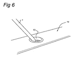
Figure 6 shows a second view. - The line indicated in its entirety by 1 in
Figure 1 , which has afibre core 2 and a plastic sheath 3 made of, for example, polyvinyl chloride, can be used in the method according to the invention. Thefibres 2 have a high tensile strength and high tensile rigidity. Consequently, the line used as washing line will not give too much and droop when heavy items are hung on it. The purpose of the polyvinyl chloride sheath 3 is merely to protect the bundle offibres 2 and to facilitate hanging up the washing. However, the flexibility of such a sheath 3 is fairly high and therefore also does not contribute to the rigidity and strength of theline 1. - With regard to the method according to the invention the
line 1 is bent over at one end, as a result of which ahead 4 is produced (Fig. 3 ), as well as afree section 5 of line adjoining the latter. This form is fixed by the squeeze piece or crimp piece indicated in its entirety by 6, the initial form of which is indicated by 7 inFigure 2a . This crimp piece is U-shaped and has two arms 8, 9 as well as anintermediate section 10. When deforming the crimp piece the arms are shaped to give the two curls indicated by 11 and 12, which are joined by theintermediate section 10 as shown inFigure 2b . Thecrimp piece 6 is shown in this latter state inFigure 3 . In this embodiment the arms 8, 9 are each pushed through theline 4, such that one half of the line in each case runs in the two spaces as defined by thecurls line 4 is thus ensured. This fastening can also be obtained by allowing the line in its entirety, that is to say not split, to run through both spaces as defined by the curls. - According to the invention a
line 1 prepared in this way is inserted in thehole 13 of the boom indicated in its entirety by 14, in this case in the arm of a rotary clothes dryer (Fig. 4 ). This boom is likewise U-shaped and has thearms Figure 5 , which are joined by an intermediate section (not visible). - During the first stage of insertion the
head 4 enters the hole. Then the portion of theline 1 around which thecrimp piece 6 has been clamped and then the free section ofline 5 that points outwards under the effect of crimping. - After the entire head, crimp
piece 6 and thefree end 1 of the line have been inserted through the hole, the line is pulled back to some extent, as a result of which the situation as shown in the view inFigure 5 is produced. In this situation both theend 5 of the line and thehead 4 bear firmly against the surroundings of thehole 13, which yields a very stable fixing between theline 1 and thearm 14, as is also shown in the view inFigure 6 . - Although reference has been made in the description to a line with a fibre core and a sheath, a wide variety of other types of lines can also be used. Rotary clothes dryers and the like have also been mentioned. This covers any equipment in which lines are attached to booms.
Claims (7)
- Method for attaching a line (1) for a washing line to a boom, such as the arm (14) of a rotary clothes dryer, comprising the following steps:- providing a barbed form (4 - 6) at one end of the line (1),- providing a boom (14) provided with an opening (13) which has dimensions that approximately correspond to those of the barbed form (4 - 6) of the line (1),- moving the boom (14) and the line (1) towards one another for taking up the barbed form (4-6) in one end of the opening (13) over a distance such that the barbed form (4-6) has emerged from the other end of the opening (13),- moving the line (1) and the boom (14) in opposing directions with respect to one another such that the barbed form (4 - 6) is held securely by hooking behind the portion of the boom (14) that surrounds the other end of the opening (13),characterized by comprising the following steps:- folding over the line (1) so as to form a folded-over head (4) and a free section of line (5) extending from the head (4) along the portion of the line (1) adjoining the head (4),- fitting a clasp (6) between the head (4) and the free section of line (5),- providing a boom (14) provided with an opening (13) which has dimensions that approximately correspond to those of the head (4) of the line (1),- moving the boom (14) and the line (1) towards one another for taking up the head (4) in one end of the opening (13) over a distance such that the head (4) and the free section of line (5) have emerged completely from the other end of the opening (13),- hooking the free section of line (5) behind the portion of the boom (14) that surrounds the other end of the opening (13).
- Method according to Claim 1,comprising hooking the head (4) behind the section of the boom (14) that surrounds the other end of the opening (13).
- Method according to Claim 1 or 2, wherein the clasp (6) is formed by crimping on a crimp piece. Line (1) for use in the method according to one of the preceding claims, having form (4 - 6) at one end.
- Line (1) for use with the method according to one of Claims and having a barbed form at one end of the line, characterized by : 1-3 having a folded-over head (4) at said one end, a free section of line (5) that extends from the head (4) along the portion of the line (1) adjoining the head, and a clasp (6) between the head (4) and the section of line (5).
- Line (1) according to Claim 4, wherein the clasp (6) is a crimp sleeve.
- Line (1) according to Claim 4 or 5, wherein a fibre core (2) is accommodated in a plastic sheath (3).
- Line (1) according to Claim 6, wherein the sheath (3) comprises polyvinyl chloride.
Applications Claiming Priority (2)
| Application Number | Priority Date | Filing Date | Title |
|---|---|---|---|
| NL1023763A NL1023763C2 (en) | 2003-06-27 | 2003-06-27 | Method for attaching a wire to a jib, as well as wire for use with such a method. |
| PCT/NL2004/000453 WO2005001190A1 (en) | 2003-06-27 | 2004-06-25 | Method for attaching a line to a boom and line for use in such a method |
Publications (2)
| Publication Number | Publication Date |
|---|---|
| EP1639181A1 EP1639181A1 (en) | 2006-03-29 |
| EP1639181B1 true EP1639181B1 (en) | 2012-11-14 |
Family
ID=33550489
Family Applications (1)
| Application Number | Title | Priority Date | Filing Date |
|---|---|---|---|
| EP04748683A Expired - Lifetime EP1639181B1 (en) | 2003-06-27 | 2004-06-25 | Method for attaching a line to a boom and line for use in such a method |
Country Status (3)
| Country | Link |
|---|---|
| EP (1) | EP1639181B1 (en) |
| NL (1) | NL1023763C2 (en) |
| WO (1) | WO2005001190A1 (en) |
Cited By (1)
| Publication number | Priority date | Publication date | Assignee | Title |
|---|---|---|---|---|
| EP4242369A1 (en) | 2022-03-08 | 2023-09-13 | Carl Freudenberg KG | Clothes drier with a device for hooking the clothesline |
Families Citing this family (1)
| Publication number | Priority date | Publication date | Assignee | Title |
|---|---|---|---|---|
| US11634276B2 (en) | 2017-11-17 | 2023-04-25 | Kohler Co. | Trash can |
Family Cites Families (7)
| Publication number | Priority date | Publication date | Assignee | Title |
|---|---|---|---|---|
| US2508491A (en) * | 1946-04-03 | 1950-05-23 | Cayo Peter | Clothesline |
| GB755619A (en) * | 1953-10-26 | 1956-08-22 | Ft Products Ltd | Improvements relating to thimbles for cords |
| DE1952037U (en) * | 1966-10-14 | 1966-12-22 | Hermann Nethe O H G | ROPE. |
| US3952376A (en) * | 1975-01-07 | 1976-04-27 | Ellis Industries, Inc. | Line connecting apparatus |
| ATE34414T1 (en) * | 1983-07-22 | 1988-06-15 | Leifheit Ag | WASHER. |
| ES2076408T3 (en) * | 1991-05-18 | 1995-11-01 | Leifheit Ag | AERATED AND DRYING FRAME. |
| US5630257A (en) * | 1994-12-07 | 1997-05-20 | Tiger Products, Inc. | Versatile adjustable fastener system |
-
2003
- 2003-06-27 NL NL1023763A patent/NL1023763C2/en not_active IP Right Cessation
-
2004
- 2004-06-25 EP EP04748683A patent/EP1639181B1/en not_active Expired - Lifetime
- 2004-06-25 WO PCT/NL2004/000453 patent/WO2005001190A1/en not_active Ceased
Cited By (1)
| Publication number | Priority date | Publication date | Assignee | Title |
|---|---|---|---|---|
| EP4242369A1 (en) | 2022-03-08 | 2023-09-13 | Carl Freudenberg KG | Clothes drier with a device for hooking the clothesline |
Also Published As
| Publication number | Publication date |
|---|---|
| EP1639181A1 (en) | 2006-03-29 |
| NL1023763C2 (en) | 2005-01-03 |
| WO2005001190A1 (en) | 2005-01-06 |
Similar Documents
| Publication | Publication Date | Title |
|---|---|---|
| US7845609B2 (en) | Loop line | |
| US7433571B2 (en) | Cable bundling and organizing system | |
| WO1998034475A1 (en) | Split ring for fishing | |
| EP1639181B1 (en) | Method for attaching a line to a boom and line for use in such a method | |
| US6751829B2 (en) | Tape-less cable connector | |
| CN108883863A (en) | Metal tape | |
| KR200326729Y1 (en) | Cable hanger | |
| JP4155432B2 (en) | Striatum holder | |
| JP3486715B2 (en) | Wire harness | |
| CN212302023U (en) | Double-hook aerial optical cable coil fixing frame | |
| KR101381584B1 (en) | Hanger for arranging incoming communication cable | |
| JP3463088B2 (en) | Handle member for wire harness and wire harness incorporating the same | |
| JP2010253009A (en) | Hanger with circular hook | |
| GB2061367A (en) | Interconnection of longitudinal edges of split mesh cable grips | |
| US5639068A (en) | Cable lead tool | |
| JP2002271935A (en) | Method for inserting wires through net tube | |
| CN218526059U (en) | Novel cable and wire clamp | |
| JP3910168B2 (en) | Spiral hanger | |
| JP2709826B2 (en) | Cable fixing method and fixing device used for it | |
| JP7136981B2 (en) | Connection tool and connection method for bundled hangers | |
| CN220097203U (en) | Can fix, ribbon structure of dismantlement | |
| JP2002354622A (en) | Cable protective pipe lead-in method | |
| KR101061809B1 (en) | Easy hanger | |
| CN116732756A (en) | Laundry dryer comprising means for gripping a clothesline | |
| CN120959091A (en) | Fruit tree shade |
Legal Events
| Date | Code | Title | Description |
|---|---|---|---|
| PUAI | Public reference made under article 153(3) epc to a published international application that has entered the european phase |
Free format text: ORIGINAL CODE: 0009012 |
|
| 17P | Request for examination filed |
Effective date: 20051128 |
|
| AK | Designated contracting states |
Kind code of ref document: A1 Designated state(s): AT BE BG CH CY CZ DE DK EE ES FI FR GB GR HU IE IT LI LU MC NL PL PT RO SE SI SK TR |
|
| DAX | Request for extension of the european patent (deleted) | ||
| 17Q | First examination report despatched |
Effective date: 20110223 |
|
| GRAP | Despatch of communication of intention to grant a patent |
Free format text: ORIGINAL CODE: EPIDOSNIGR1 |
|
| GRAS | Grant fee paid |
Free format text: ORIGINAL CODE: EPIDOSNIGR3 |
|
| GRAA | (expected) grant |
Free format text: ORIGINAL CODE: 0009210 |
|
| AK | Designated contracting states |
Kind code of ref document: B1 Designated state(s): AT BE BG CH CY CZ DE DK EE ES FI FR GB GR HU IE IT LI LU MC NL PL PT RO SE SI SK TR |
|
| REG | Reference to a national code |
Ref country code: GB Ref legal event code: FG4D |
|
| REG | Reference to a national code |
Ref country code: CH Ref legal event code: EP Ref country code: AT Ref legal event code: REF Ref document number: 584086 Country of ref document: AT Kind code of ref document: T Effective date: 20121115 |
|
| REG | Reference to a national code |
Ref country code: NL Ref legal event code: T3 Ref country code: IE Ref legal event code: FG4D |
|
| REG | Reference to a national code |
Ref country code: DE Ref legal event code: R096 Ref document number: 602004040043 Country of ref document: DE Effective date: 20130110 |
|
| REG | Reference to a national code |
Ref country code: AT Ref legal event code: MK05 Ref document number: 584086 Country of ref document: AT Kind code of ref document: T Effective date: 20121114 |
|
| PG25 | Lapsed in a contracting state [announced via postgrant information from national office to epo] |
Ref country code: ES Free format text: LAPSE BECAUSE OF FAILURE TO SUBMIT A TRANSLATION OF THE DESCRIPTION OR TO PAY THE FEE WITHIN THE PRESCRIBED TIME-LIMIT Effective date: 20130225 Ref country code: SE Free format text: LAPSE BECAUSE OF FAILURE TO SUBMIT A TRANSLATION OF THE DESCRIPTION OR TO PAY THE FEE WITHIN THE PRESCRIBED TIME-LIMIT Effective date: 20121114 Ref country code: FI Free format text: LAPSE BECAUSE OF FAILURE TO SUBMIT A TRANSLATION OF THE DESCRIPTION OR TO PAY THE FEE WITHIN THE PRESCRIBED TIME-LIMIT Effective date: 20121114 |
|
| PG25 | Lapsed in a contracting state [announced via postgrant information from national office to epo] |
Ref country code: GR Free format text: LAPSE BECAUSE OF FAILURE TO SUBMIT A TRANSLATION OF THE DESCRIPTION OR TO PAY THE FEE WITHIN THE PRESCRIBED TIME-LIMIT Effective date: 20130215 Ref country code: PL Free format text: LAPSE BECAUSE OF FAILURE TO SUBMIT A TRANSLATION OF THE DESCRIPTION OR TO PAY THE FEE WITHIN THE PRESCRIBED TIME-LIMIT Effective date: 20121114 Ref country code: CY Free format text: LAPSE BECAUSE OF FAILURE TO SUBMIT A TRANSLATION OF THE DESCRIPTION OR TO PAY THE FEE WITHIN THE PRESCRIBED TIME-LIMIT Effective date: 20121114 Ref country code: SI Free format text: LAPSE BECAUSE OF FAILURE TO SUBMIT A TRANSLATION OF THE DESCRIPTION OR TO PAY THE FEE WITHIN THE PRESCRIBED TIME-LIMIT Effective date: 20121114 Ref country code: PT Free format text: LAPSE BECAUSE OF FAILURE TO SUBMIT A TRANSLATION OF THE DESCRIPTION OR TO PAY THE FEE WITHIN THE PRESCRIBED TIME-LIMIT Effective date: 20130314 |
|
| PG25 | Lapsed in a contracting state [announced via postgrant information from national office to epo] |
Ref country code: AT Free format text: LAPSE BECAUSE OF FAILURE TO SUBMIT A TRANSLATION OF THE DESCRIPTION OR TO PAY THE FEE WITHIN THE PRESCRIBED TIME-LIMIT Effective date: 20121114 |
|
| PG25 | Lapsed in a contracting state [announced via postgrant information from national office to epo] |
Ref country code: EE Free format text: LAPSE BECAUSE OF FAILURE TO SUBMIT A TRANSLATION OF THE DESCRIPTION OR TO PAY THE FEE WITHIN THE PRESCRIBED TIME-LIMIT Effective date: 20121114 Ref country code: SK Free format text: LAPSE BECAUSE OF FAILURE TO SUBMIT A TRANSLATION OF THE DESCRIPTION OR TO PAY THE FEE WITHIN THE PRESCRIBED TIME-LIMIT Effective date: 20121114 Ref country code: BG Free format text: LAPSE BECAUSE OF FAILURE TO SUBMIT A TRANSLATION OF THE DESCRIPTION OR TO PAY THE FEE WITHIN THE PRESCRIBED TIME-LIMIT Effective date: 20130214 Ref country code: DK Free format text: LAPSE BECAUSE OF FAILURE TO SUBMIT A TRANSLATION OF THE DESCRIPTION OR TO PAY THE FEE WITHIN THE PRESCRIBED TIME-LIMIT Effective date: 20121114 Ref country code: CZ Free format text: LAPSE BECAUSE OF FAILURE TO SUBMIT A TRANSLATION OF THE DESCRIPTION OR TO PAY THE FEE WITHIN THE PRESCRIBED TIME-LIMIT Effective date: 20121114 |
|
| PG25 | Lapsed in a contracting state [announced via postgrant information from national office to epo] |
Ref country code: RO Free format text: LAPSE BECAUSE OF FAILURE TO SUBMIT A TRANSLATION OF THE DESCRIPTION OR TO PAY THE FEE WITHIN THE PRESCRIBED TIME-LIMIT Effective date: 20121114 Ref country code: IT Free format text: LAPSE BECAUSE OF FAILURE TO SUBMIT A TRANSLATION OF THE DESCRIPTION OR TO PAY THE FEE WITHIN THE PRESCRIBED TIME-LIMIT Effective date: 20121114 |
|
| PLBE | No opposition filed within time limit |
Free format text: ORIGINAL CODE: 0009261 |
|
| STAA | Information on the status of an ep patent application or granted ep patent |
Free format text: STATUS: NO OPPOSITION FILED WITHIN TIME LIMIT |
|
| 26N | No opposition filed |
Effective date: 20130815 |
|
| REG | Reference to a national code |
Ref country code: DE Ref legal event code: R097 Ref document number: 602004040043 Country of ref document: DE Effective date: 20130815 |
|
| PG25 | Lapsed in a contracting state [announced via postgrant information from national office to epo] |
Ref country code: MC Free format text: LAPSE BECAUSE OF FAILURE TO SUBMIT A TRANSLATION OF THE DESCRIPTION OR TO PAY THE FEE WITHIN THE PRESCRIBED TIME-LIMIT Effective date: 20121114 |
|
| REG | Reference to a national code |
Ref country code: CH Ref legal event code: PL |
|
| REG | Reference to a national code |
Ref country code: IE Ref legal event code: MM4A |
|
| PG25 | Lapsed in a contracting state [announced via postgrant information from national office to epo] |
Ref country code: CH Free format text: LAPSE BECAUSE OF NON-PAYMENT OF DUE FEES Effective date: 20130630 Ref country code: LI Free format text: LAPSE BECAUSE OF NON-PAYMENT OF DUE FEES Effective date: 20130630 Ref country code: IE Free format text: LAPSE BECAUSE OF NON-PAYMENT OF DUE FEES Effective date: 20130625 |
|
| PG25 | Lapsed in a contracting state [announced via postgrant information from national office to epo] |
Ref country code: TR Free format text: LAPSE BECAUSE OF FAILURE TO SUBMIT A TRANSLATION OF THE DESCRIPTION OR TO PAY THE FEE WITHIN THE PRESCRIBED TIME-LIMIT Effective date: 20121114 |
|
| REG | Reference to a national code |
Ref country code: FR Ref legal event code: PLFP Year of fee payment: 12 |
|
| PG25 | Lapsed in a contracting state [announced via postgrant information from national office to epo] |
Ref country code: HU Free format text: LAPSE BECAUSE OF FAILURE TO SUBMIT A TRANSLATION OF THE DESCRIPTION OR TO PAY THE FEE WITHIN THE PRESCRIBED TIME-LIMIT; INVALID AB INITIO Effective date: 20040625 Ref country code: LU Free format text: LAPSE BECAUSE OF NON-PAYMENT OF DUE FEES Effective date: 20130625 |
|
| PGFP | Annual fee paid to national office [announced via postgrant information from national office to epo] |
Ref country code: GB Payment date: 20150630 Year of fee payment: 12 |
|
| PGFP | Annual fee paid to national office [announced via postgrant information from national office to epo] |
Ref country code: NL Payment date: 20150626 Year of fee payment: 12 Ref country code: FR Payment date: 20150630 Year of fee payment: 12 |
|
| PGFP | Annual fee paid to national office [announced via postgrant information from national office to epo] |
Ref country code: DE Payment date: 20150831 Year of fee payment: 12 |
|
| PGFP | Annual fee paid to national office [announced via postgrant information from national office to epo] |
Ref country code: BE Payment date: 20150629 Year of fee payment: 12 |
|
| PG25 | Lapsed in a contracting state [announced via postgrant information from national office to epo] |
Ref country code: BE Free format text: LAPSE BECAUSE OF NON-PAYMENT OF DUE FEES Effective date: 20160630 |
|
| REG | Reference to a national code |
Ref country code: DE Ref legal event code: R119 Ref document number: 602004040043 Country of ref document: DE |
|
| REG | Reference to a national code |
Ref country code: NL Ref legal event code: MM Effective date: 20160701 |
|
| GBPC | Gb: european patent ceased through non-payment of renewal fee |
Effective date: 20160625 |
|
| REG | Reference to a national code |
Ref country code: FR Ref legal event code: ST Effective date: 20170228 |
|
| PG25 | Lapsed in a contracting state [announced via postgrant information from national office to epo] |
Ref country code: FR Free format text: LAPSE BECAUSE OF NON-PAYMENT OF DUE FEES Effective date: 20160630 Ref country code: DE Free format text: LAPSE BECAUSE OF NON-PAYMENT OF DUE FEES Effective date: 20170103 |
|
| PG25 | Lapsed in a contracting state [announced via postgrant information from national office to epo] |
Ref country code: NL Free format text: LAPSE BECAUSE OF NON-PAYMENT OF DUE FEES Effective date: 20160701 Ref country code: GB Free format text: LAPSE BECAUSE OF NON-PAYMENT OF DUE FEES Effective date: 20160625 |