EP1638132B1 - Mass chromatography - Google Patents
Mass chromatography Download PDFInfo
- Publication number
- EP1638132B1 EP1638132B1 EP05004827.1A EP05004827A EP1638132B1 EP 1638132 B1 EP1638132 B1 EP 1638132B1 EP 05004827 A EP05004827 A EP 05004827A EP 1638132 B1 EP1638132 B1 EP 1638132B1
- Authority
- EP
- European Patent Office
- Prior art keywords
- ion
- sample
- aperture
- gas
- column
- Prior art date
- Legal status (The legal status is an assumption and is not a legal conclusion. Google has not performed a legal analysis and makes no representation as to the accuracy of the status listed.)
- Expired - Fee Related
Links
- 238000004587 chromatography analysis Methods 0.000 title 1
- 238000004458 analytical method Methods 0.000 claims description 29
- 238000004817 gas chromatography Methods 0.000 claims description 6
- 238000000065 atmospheric pressure chemical ionisation Methods 0.000 claims description 5
- 150000002500 ions Chemical class 0.000 description 401
- 239000007789 gas Substances 0.000 description 218
- 230000035945 sensitivity Effects 0.000 description 61
- 238000010276 construction Methods 0.000 description 25
- 230000014509 gene expression Effects 0.000 description 20
- 239000012535 impurity Substances 0.000 description 16
- 238000005259 measurement Methods 0.000 description 16
- 230000014759 maintenance of location Effects 0.000 description 14
- 239000012159 carrier gas Substances 0.000 description 13
- 230000035484 reaction time Effects 0.000 description 11
- 230000008859 change Effects 0.000 description 10
- 238000011109 contamination Methods 0.000 description 7
- 238000010790 dilution Methods 0.000 description 7
- 239000012895 dilution Substances 0.000 description 7
- 230000007935 neutral effect Effects 0.000 description 6
- 239000013598 vector Substances 0.000 description 6
- 238000005192 partition Methods 0.000 description 5
- 230000001105 regulatory effect Effects 0.000 description 5
- IJGRMHOSHXDMSA-UHFFFAOYSA-N Atomic nitrogen Chemical compound N#N IJGRMHOSHXDMSA-UHFFFAOYSA-N 0.000 description 4
- 238000002290 gas chromatography-mass spectrometry Methods 0.000 description 4
- 238000010206 sensitivity analysis Methods 0.000 description 4
- 238000000926 separation method Methods 0.000 description 4
- YXFVVABEGXRONW-UHFFFAOYSA-N Toluene Chemical compound CC1=CC=CC=C1 YXFVVABEGXRONW-UHFFFAOYSA-N 0.000 description 3
- 238000010586 diagram Methods 0.000 description 3
- 238000005040 ion trap Methods 0.000 description 3
- 238000004949 mass spectrometry Methods 0.000 description 3
- 239000000463 material Substances 0.000 description 3
- HSQFVBWFPBKHEB-UHFFFAOYSA-N 2,3,4-trichlorophenol Chemical compound OC1=CC=C(Cl)C(Cl)=C1Cl HSQFVBWFPBKHEB-UHFFFAOYSA-N 0.000 description 2
- XKRFYHLGVUSROY-UHFFFAOYSA-N Argon Chemical compound [Ar] XKRFYHLGVUSROY-UHFFFAOYSA-N 0.000 description 2
- 238000000451 chemical ionisation Methods 0.000 description 2
- 230000007423 decrease Effects 0.000 description 2
- 238000001514 detection method Methods 0.000 description 2
- 230000005684 electric field Effects 0.000 description 2
- 238000005516 engineering process Methods 0.000 description 2
- 239000001307 helium Substances 0.000 description 2
- 229910052734 helium Inorganic materials 0.000 description 2
- SWQJXJOGLNCZEY-UHFFFAOYSA-N helium atom Chemical compound [He] SWQJXJOGLNCZEY-UHFFFAOYSA-N 0.000 description 2
- 239000007788 liquid Substances 0.000 description 2
- 238000000034 method Methods 0.000 description 2
- 229910052757 nitrogen Inorganic materials 0.000 description 2
- 239000004065 semiconductor Substances 0.000 description 2
- 239000000126 substance Substances 0.000 description 2
- BLRPTPMANUNPDV-UHFFFAOYSA-N Silane Chemical compound [SiH4] BLRPTPMANUNPDV-UHFFFAOYSA-N 0.000 description 1
- 239000003570 air Substances 0.000 description 1
- 229910052786 argon Inorganic materials 0.000 description 1
- 238000000668 atmospheric pressure chemical ionisation mass spectrometry Methods 0.000 description 1
- 230000033228 biological regulation Effects 0.000 description 1
- 238000003965 capillary gas chromatography Methods 0.000 description 1
- 238000004140 cleaning Methods 0.000 description 1
- 239000000470 constituent Substances 0.000 description 1
- 230000003247 decreasing effect Effects 0.000 description 1
- 238000007599 discharging Methods 0.000 description 1
- PZPGRFITIJYNEJ-UHFFFAOYSA-N disilane Chemical compound [SiH3][SiH3] PZPGRFITIJYNEJ-UHFFFAOYSA-N 0.000 description 1
- 230000000694 effects Effects 0.000 description 1
- 230000007613 environmental effect Effects 0.000 description 1
- 238000010438 heat treatment Methods 0.000 description 1
- 239000011261 inert gas Substances 0.000 description 1
- 238000000752 ionisation method Methods 0.000 description 1
- 238000012423 maintenance Methods 0.000 description 1
- 238000012986 modification Methods 0.000 description 1
- 230000004048 modification Effects 0.000 description 1
- 230000008569 process Effects 0.000 description 1
- 239000007787 solid Substances 0.000 description 1
- 239000000243 solution Substances 0.000 description 1
- 230000032258 transport Effects 0.000 description 1
Images


Classifications
-
- H—ELECTRICITY
- H01—ELECTRIC ELEMENTS
- H01J—ELECTRIC DISCHARGE TUBES OR DISCHARGE LAMPS
- H01J49/00—Particle spectrometers or separator tubes
- H01J49/02—Details
- H01J49/04—Arrangements for introducing or extracting samples to be analysed, e.g. vacuum locks; Arrangements for external adjustment of electron- or ion-optical components
- H01J49/0422—Arrangements for introducing or extracting samples to be analysed, e.g. vacuum locks; Arrangements for external adjustment of electron- or ion-optical components for gaseous samples
-
- G—PHYSICS
- G01—MEASURING; TESTING
- G01N—INVESTIGATING OR ANALYSING MATERIALS BY DETERMINING THEIR CHEMICAL OR PHYSICAL PROPERTIES
- G01N30/00—Investigating or analysing materials by separation into components using adsorption, absorption or similar phenomena or using ion-exchange, e.g. chromatography or field flow fractionation
- G01N30/02—Column chromatography
- G01N30/62—Detectors specially adapted therefor
- G01N30/72—Mass spectrometers
- G01N30/7206—Mass spectrometers interfaced to gas chromatograph
- G01N30/7213—Mass spectrometers interfaced to gas chromatograph splitting of the gaseous effluent
-
- H—ELECTRICITY
- H01—ELECTRIC ELEMENTS
- H01J—ELECTRIC DISCHARGE TUBES OR DISCHARGE LAMPS
- H01J49/00—Particle spectrometers or separator tubes
- H01J49/02—Details
- H01J49/10—Ion sources; Ion guns
- H01J49/14—Ion sources; Ion guns using particle bombardment, e.g. ionisation chambers
- H01J49/145—Ion sources; Ion guns using particle bombardment, e.g. ionisation chambers using chemical ionisation
-
- H—ELECTRICITY
- H01—ELECTRIC ELEMENTS
- H01J—ELECTRIC DISCHARGE TUBES OR DISCHARGE LAMPS
- H01J49/00—Particle spectrometers or separator tubes
- H01J49/02—Details
- H01J49/10—Ion sources; Ion guns
- H01J49/16—Ion sources; Ion guns using surface ionisation, e.g. field-, thermionic- or photo-emission
- H01J49/168—Ion sources; Ion guns using surface ionisation, e.g. field-, thermionic- or photo-emission field ionisation, e.g. corona discharge
Definitions
- This invention relates to an atmospheric pressure chemical ionization mass spectrometry for analyzing a sample gas separated by gas chromatography.
- gas chromatography will be abbreviated as "GC”, a mass spectrometer, as “MS”, an apparatus including the combination of the gas chromatography and the mass spectrometer, as “GC/MS”, an atmospheric pressure chemical ionization source, as “APCI source”, an atmospheric pressure chemical ionization mass spectrometer (apparatus including the combination of APCI and MS), as “APCI/MS”, a chemical ionization source, as “CI source”, an electron impact ion source, as "EI source”, and an apparatus including the combination of the gas chromatography and the atmospheric pressure chemical ionization mass spectrometer, as "GC/APCI/MS”.
- GC/MS is a known analytic technology.
- APCI/MS is an apparatus that ionizes trace components in a mixed sample and detects them with a high level of sensitivity by using an ion-molecule reaction. This apparatus has been utilized for the analysis of the trace components contained in environmental samples and living body samples.
- Another report (refer to JP-A-6-310091 ) is known that separates an ion generation portion and a sample gas introduction portion and efficiently transports ions into apertures so that trace impurities can be measured with a high sensitivity and stably for a long time even for those semiconductor material gases such as monosilane and disilane that are likely to invite contamination inside an ion source.
- the sample gas separated in a column of the GC is mixed with a carrier gas and is then introduced to an APCI source through a line.
- the flow rate of the carrier gas flowing through the line is set to a minimum flow rate that can keep the atmospheric pressure inside a discharge space of the APCI source for the purpose of high sensitivity analysis.
- An orifice is disposed so that the discharge space can be kept steadily and easily at the atmospheric pressure and the flow rate of an exhaust line can be regulated to the minimum flow rate.
- JP-A-11-295269 there is an introduction system extending to APCI/MS through GC and a makeup flow passage connected to an outflow passage from GC is disposed.
- the reference puts the following description:
- the flow rate of the sample gas introduced into APCI/MS is generally from hundreds of mL (milliliters)/min to several L/min.
- the flow rate of the carrier gas of GC is generally 20 to 50 mL/min. It is therefore necessary to add a corresponding amount of a makeup gas from the makeup passage to the outflow gas from GC. Because this makeup gas dilutes the impurities as the assumed objects, however, its flow rate must be reduced as much as possible. To improve the sensitivity of the impurities in the analysis through GC, therefore, it is preferred to minimize the flow rate of the sample gas introduced into APCI/MS such as about 300 mL/min.”
- JP-A-6-310091 puts the following description:
- ... includes an ion generation portion as an area for generating a primary ion, having an introduction port of a primary ion generation gas and ionization means, a sample introduction portion as an area into which the sample gas is introduced, a mixing portion in which the primary ion supplied with the primary ion generation gas from the ion generation portion is mixed with the sample gas and ions of an object material in the sample gas are generated by an ion-molecule reaction, and a mass analysis portion which is held under high vacuum and in which the ion introduced from the mixing portion through an aperture is subjected to mass separation, wherein at least one of means for transporting the ion to the aperture by adding an electric field by an electrode disposed in the mixing portion, means for constituting the ion generation portion and the sample introduction portion into a double wall tube and making the flow of the primary ion generation gas and the flow of the sample gas parallel to each other in the mixing portion, and means for discharging the gas reaching the aperture in a direction extending along a surface having the aperture is
- JP-A-6-310091 reads as follows:
- the primary ion is injected with the primary ion generation gas under the atmospheric pressure and the primary ion is mixed with the sample gas at the atmospheric pressure ahead of the aperture of the mass analysis portion.
- the ion of the object material is generated by the ion-molecule reaction. Because the ion generation portion and the sample introduction portion are separated in APCI/MS, the ion generation portion is not contaminated even when a gas flowing out from GC and LC (liquid chromatograph) is used as the sample gas and ionization can be carried out stably for a long time".
- JP-A-9-15207 the sample gas separated in the column of GC is mixed with the carrier gas and is introduced into the APCI source through the line.
- the outflow gas from GC is introduced into APCI/Ms after the makeup gas is added from the makeup passage. Therefore, the outflow gas from GC is diluted. Because ionization of the sample described in "Prior Art" in JP-A-6-310091 is conducted at the atmospheric pressure, the outflow gas from GC is diluted, too.
- the analysis by GC/MS is suitable for separation analysis of a plurality of components contained in a mixed sample, particularly for separation analysis of components having high volatility.
- the ion source used for GC/MS generally includes a CI source and an EI source. These ion sources are used for ionization under vacuum of about 0.1 torr to several torr.
- the sample gas separated by GC is introduced into the ion source under this vacuum.
- the impurities are adsorbed to the wall of the ion source and to constituent components and remain inside the ion source. Consequently, the ion source is contaminated and an S/N ratio gets decreased. Therefore, maintenance such as frequent cleaning of the ion source is necessary and hinders efficient analysis.
- ionization of the sample is conducted at the atmospheric pressure and a differential exhaust portion for transporting the ion from the ion source to the mass analysis portion under vacuum is disposed.
- the ion from the ion source is introduced into the vacuum portion through an ion introduction aperture having a diameter of about 0.1 to about 0.5 mm ⁇ .
- a gas (primary ion generation gas (discharge gas)) of a flow rate of about 0.1 to about 1 L/min must be caused to flow steadily to the ion source and the gas flow rate flowing through the ion introduction aperture is about 0.1 to about 1 L/min.
- the gas from GC is diluted by the primary ion generation gas that is caused to flow to the ion source.
- the problem of the drop of sensitivity occurs when the gas from GC is merely mixed with the primary ion generation gas.
- US 2003/015657 A1 discloses a mass spectrometer related to the one of the present invention.
- the APCI source includes a first ionization portion for generating a primary ion from a primary ion generation gas by corona discharge generated by a voltage applied to a needle electrode disposed inside the first ionization portion, and a second ionization portion for generating a sample ion by an ion-molecule reaction between the sample gas directly introduced from an end of a GC column and the primary ion sent from the first ionization portion, having an aperture at the end of the GC column disposed therein.
- the sample gas separated in the GC column contains a single component completely separated or a plurality of components not completely separated.
- the first ionization portion and the second ionization portion are separated from each other by a lead-out electrode having a primary ion introduction aperture through which the primary ion passes.
- the primary ion generation gas introduced into the second ionization portion passes through the primary ion introduction aperture, flows to the tip end of the needle electrode and is exhausted from the first ionization portion.
- the sample ion generated in the second ionization portion is introduced into the mass analysis portion through the sample ion movement aperture, the differential exhaust portion and the sample ion introduction aperture and is subjected to mass analysis.
- the sample gas is directly introduced from a position in the proximity of an axis connecting the center of the primary ion introduction aperture through which the primary ion passes and the center of the sample ion movement aperture through which the sample ion moves, into the second ionization portion from the aperture at the end of the GC column.
- the center of the aperture at the end of the GC column is arranged at the position that is substantially equidistant from the center of an ion outlet of the primary ion introduction aperture and from the center of an ion inlet of the sample ion movement aperture and satisfies the relation r ⁇ 2R where R is a radius of the primary ion introduction aperture and r is a distance from the axis connecting the center of the primary ion introduction aperture to the center of the sample ion movement aperture.
- the sample gas that is directly introduced with the carrier gas from the aperture at the end of the GC column into the second ionization portion under the state where it is not diluted flows to the primary ion introduction aperture and to the sample ion movement aperture at substantially the same flow rate along the axis connecting the center of the primary ion introduction aperture to the center of the sample ion movement aperture.
- the retention time in which the primary ion and the sample molecule coexist in the field of the ion-molecule reaction as the field in which the primary ion and the sample molecule react with each other becomes long and a sufficient time for the progress of the ion-molecule reaction can be secured.
- the sample molecule can be efficiently ionized, the generation amount of the sample ion increases and the sensitivity can be improved.
- the APCI source (first ionization portion, second ionization portion, needle electrode, apertures) is not contaminated by the impurities contained in the sample gas and the analysis can be carried out at a high sensitivity without being affected by the impurities.
- the mass spectrometer (GC/APCI/MS) can analyze at a high sensitivity the mixed sample containing large amounts of impurities without contamination of the ion source by the impurities.
- the invention can provide an APCI source not generating contamination and a mass spectrometer (GC/APCI/MS) and a mass spectrometry using the APCI source and capable of high sensitivity analysis without being affected by dilution of a sample gas by a primary ion generation gas.
- GC/APCI/MS mass spectrometer
- the invention employs a construction in which a sample gas is directly introduced into the field of an ion-molecule reaction capable of ionization with high efficiency and the resulting sample ion is introduced highly efficiently into a mass analysis portion. Therefore, the invention can prevent the drop of sensitivity due to dilution of the sample gas before its introduction into an ion source and contamination of the ion source, and makes it possible to conduct high sensitivity analysis.
- Fig. 1 is a sectional view showing a construction of a mass spectrometer according to a first embodiment of the invention.
- This mass spectrometer (GC/APCI/MS) is a high sensitivity apparatus that ionizes sample molecules (sample gas) separated by a GC column by an APCI source and analyzes the mass.
- a first ionization portion 3 and a second ionization portion 5 are separated from each other by a first partition (lead-out electrode 4) having a primary ion introduction aperture 11 through which a primary ion passes.
- the second ionization portion 5 is an area that is interposed by the first partition and a second partition that has a sample ion movement aperture 8 through which a sample ion of a sample gas generated by the reaction between the sample molecule and the primary ion (hereinafter called "ion-molecule reaction") inside the second ionization portion 5 passes.
- the mass spectrometer includes the first ionization portion 3, the second ionization portion 5, a differential exhaust portion 17 and a mass analysis portion 15.
- the first ionization portion 3 and the second ionization portion 5 are separated by the lead-out electrode 4 having the primary ion introduction aperture 11 and the second ionization portion 5 and the differential exhaust portion 17 are separated by a wall having the sample ion movement aperture 8.
- the differential exhaust portion 17 and the mass analysis portion 11 are separated by a wall having an ion introduction aperture 14.
- the primary ion introduction aperture 11 is an aperture through which the primary ion generated in the first ionization portion 3 moves and the sample ion movement aperture 8 is an aperture through which the sample ion generated in the second ionization portion 5 moves.
- the ion introduction aperture 14 is an aperture for introducing the sample ion into the mass analysis portion 15. The sample ion moves into the mass analysis portion 15 through the sample ion movement aperture 8, the differential exhaust portion 17 and the ion introduction aperture 14.
- the needle electrode 10 is arranged inside the first ionization portion 3 as a corona discharge portion and a primary ion generation gas exhaust piping 7 is connected.
- the primary ion generation gas exhaust piping 7 is connected to the first ionization portion 3 at a position far from the lead-out electrode 4 (position on the root side of needle electrode 10) on the opposite side to the tip end of the needle electrode 10.
- a primary ion generation gas introduction piping 1 for supplying a primary ion generation gas from a gas cylinder 2 is connected to the second ionization portion 5.
- the primary ion generation gas from the gas cylinder 2 is introduced through the primary ion generation gas introduction piping 1 into the second ionization portion 5 while its flow rate is regulated by a mass flow controller 6.
- the primary ion generation gas is preferably the one that does not impedes ionization of the sample gas introduced from the aperture 12 at the end of the GC column 9 into the second ionization portion 5, such as air, nitrogen, or helium and argon having low ionization efficiency.
- a high voltage is applied to the needle electrode 10 and the primary ion generation gas is ionized due to corona discharge to generate the primary ion.
- the primary ion generation gas introduced into the second ionization portion 5 and the sample gas flow along an axis (indicated by one-dot-chain line in Fig. 1 ) connecting the center of the primary ion introduction aperture 11 to the center of the sample ion movement aperture 8 into the first ionization portion 3 through the primary ion introduction aperture 11 and into the differential exhaust portion 17 through the sample ion movement aperture 8.
- the primary ion flows also into the second ionization portion 5 along the axis indicated by one-dot-chain line in Fig. 1 .
- the field of the ion-molecule reaction in which the ion-molecule reaction proceeds is an area in the proximity of the axis in which the primary ion and the sample molecule coexist and which is indicated by one-dot chain line in Fig. 1 .
- the flow rate of the primary ion generation gas to be introduced into the second ionization portion 5 is the balance obtained by subtracting the flow rate of the sample gas introduced from the aperture 12 at the end of the GC column 9 into the second ionization portion 5 from the sum of the flow rate of the gas exhausted from the primary ion generation gas exhaust piping 7 and the flow rate of the gas flowing out from the sample ion movement aperture 8 into the differential exhaust portion 17.
- the mass flow controller 6 arranged in the primary ion generation gas introduction piping 1 or a mass flow controller (not shown) arranged in the primary ion generation gas exhaust piping 7 regulates the flow rate of the primary ion generation gas.
- the sample (mixed sample) is introduced with a carrier gas 13 into one of the ends (inlet) of the GC column 9 and is separated.
- a liquid sample is injected into the inlet of the GC column 9 or a gas of components adsorbed to a solid and desorbed by heating is introduced into the GC column 9.
- the carrier gas 13 allowed to flow into the GC column 9 is preferably helium or nitrogen as an inert gas.
- the mass flow controller or a pressure controller controls the flow rate of the carrier gas 13 to a constant flow rate.
- the center of the aperture 12 at the end (other end) of the GC column 9 is arranged in the proximity of the axis indicated by one-dot-chain line in Fig. 1 . Because the aperture 12 at the end of the GC column 9 for introducing the sample gas (which flows through the GC column with the carrier gas and contains a single component separated completely or a plurality of components not completely separated) separated by the GC column 9 is arranged in the proximity of the axis indicated by one-dot-chain line in Fig. 1 , dilution of the sample as by the primary ion generation gas can be prevented and high sensitivity can be achieved.
- the detailed explanation of the position at which the center of the aperture 12 at the end of the GC column 9 is arranged will be given later.
- the lead-out electrode 4 leads out the primary ion, the sample gas is introduced into the position in the proximity of the axis indicated by one-dot-chain line in Fig. 1 and the sample ion is generated by the ion-molecule reaction.
- the sample gas introduced from the aperture 12 at the end of the GC column 9 is diluted inside the second ionization portion 5 and is exhausted from the sample ion movement aperture 8 and the primary ion introduction aperture 11.
- the center of the aperture 12 at the end of the GC column 9 is arranged at a position substantially equidistant from the center of the ion outlet of the primary ion introduction aperture 11 and from the center of the ion inlet of the sample ion movement aperture 8, the sample gas introduced from the aperture 12 at the end of the GC column 9 is discharged with good balance from the primary ion introduction aperture 11 and the sample ion movement aperture 8.
- the retention time in which the primary ion and the sample molecule coexist can be extended and the sufficient time for the progress of the ion-molecule reaction can be secured.
- the generation amount of the sample ion can be increased and the sensitivity can be improved. The process in which the sample ion is generated will be later explained in detail.
- the tip end of the needle electrode 10, the center of the primary ion introduction aperture 11, the center of the sample ion movement aperture 8 and the center of the ion introduction aperture 14 are arranged on the same axis in the construction of the first embodiment but they can be so arranged as to be deviated from one another. When they are arranged in deviation, it is possible to prevent the neutral molecule from mixing into the mass analysis portion 15 and to reduce the noise resulting from the neutral molecule.
- the sample ion generated at the position in the proximity of the axis indicated by one-dot-chain line in Fig. 1 inside the second ionization portion 5 is caused to flow through the sample ion movement aperture 8 by the potential applied between the sample ion movement aperture 8 and the ion introduction aperture 14, is introduced in the direction indicated by arrows into the mass analysis portion 15 exhausted to high vacuum by an exhaust system not shown in the drawing through the ion introduction aperture 14, and mass analysis of the sample ion is made.
- Mass spectrometers such as a quadrupole mass spectrometer, an ion trap mass spectrometer, an ion trap TOF (time of-flight) mass spectrometer, magnetic section mass spectrometer, etc, can be applied to the mass analysis portion 15.
- the primary ion generation gas flowing through the sample ion movement aperture 8 and the sample gas are exhausted by an exhaust system, not shown, for exhausting the differential exhaust portion 17.
- the second ionization portion 5 is at 760 Torr (atmospheric pressure). Therefore, the flow rate of the gas flowing through the sample ion movement aperture 8 is about 350 mL/min.
- the introduction amount of the primary ion generation gas is 1,000 mL/min
- the flow rate of the gas flowing out from the primary ion introduction aperture 11 into the first ionization portion 3 is about 650 mL/min.
- the sample is separated by the GC column 9 and the sample components so separated are serially introduced with the carrier gas 13 from the aperture 12 at the end of the GC column 9 into the second ionization portion 5.
- the flow rate of the carrier gas 13 is several mL/min and the sample gas from the GC column 9 is introduced to the position in the proximity of the axis indicated by one-dot-chain line in Fig. 1 . Therefore, the generation amount of the sample ion can be increased.
- the sample gas flowing into the second ionization portion 5 flows along the axis indicated by one-dot-chain line in Fig. 1 and is sufficiently diluted by the primary ion generation gas passing through the primary ion introduction aperture 11. Consequently, the inner wall of the second ionization portion 5 is not contaminated by impurities contained in the sample gas.
- the outline of the ionization process of the sample gas is as follows. The explanation will be given on the case of positive ionization by way of example. Corona discharge is induced between the needle electrode 10 to which a high voltage of about +4 kV is applied and the lead-out electrode 4 to which about +1 kV is applied.
- the primary ion N 2 + or N 4 +
- the primary ion N 2 + or N 4 +
- the primary ion introduction aperture 11 having a diameter of about 2 mm ⁇ is formed in the lead-out electrode 4, the resulting primary ion is introduced by the electric field into the second ionization portion 5.
- the ion of the sample gas (secondary ion: sample ion) is generated inside the second ionization portion 5 by the ion-molecule reaction between the primary ion generated by the corona discharge and the sample gas introduced from the aperture 12 at the end of the GC column 9.
- the construction of the first embodiment shown in Fig. 1 is particularly effective when negative ionization of the sample gas is conducted.
- negative ionization of the sample gas is conducted by using air for the primary ion generation gas
- the primary ion generation gas flows from the needle tip of the needle electrode 10 towards its root and the reaction between the radical NO* resulting from the corona discharge and the primary ion O 2 - can be suppressed.
- the sensitivity can be improved because O 2 - led out to the second ionization portion 5 efficiently reacts with the sample gas introduced from the aperture 12 at the end of the GC column 9.
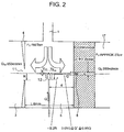
- Fig. 2 is a partial enlarged view of Fig. 1 and explains the center position of the aperture 12 at the end of the GC column 9 and the flow of the gas inside the second ionization portion 5.
- the pressure P 1 of the second ionization portion 5 is 760 Torr
- the pressure P 2 of the differential exhaust portion 17 is 2 Torr
- the amount Q 8 of the gas that flows into the sample ion movement aperture 8 is about 350 mL/min.
- the position in the proximity of the axis indicated by one-dot-chain line in Figs. 1 and 2 is the area in which the concentration of the primary ion generated by the corona discharge is high and when the sample gas is directly injected into this area, a high sensitivity can be achieved.
- the construction satisfies the relation r ⁇ 2R where R is the inner diameter (radius) of the primary ion introduction aperture 11 and r is the distance between the center of the aperture 12 at the end of the GC column 9 and the axis indicated by one-dot-chain line.
- the center of the aperture 12 at the end of the GC column 9 in the direction of the axis indicated by one-dot-chain line in Figs. 1 and 2 is preferably arranged at the position that can extend the coexistence retention time of the primary ion and the sample molecule in the field of the ion-molecule reaction and can secure the sufficient reaction time.
- the center of the aperture 12 at the end of the GC column 9 at the position at which the sample gas introduced from the aperture 12 at the end of the GC column 9 can be discharged with good balance from the primary ion introduction aperture 11 and from the sample ion movement aperture 8 inside the second ionization portion 5.
- the coexistence retention time of the primary ion and the sample molecule in the field of the ion-molecule reaction can be sufficiently extended, the sufficient time for the progress of the ion-molecule reaction can be secured, too, the generation amount of the sample ion can be increased and the sensitivity can be improved.
- the position from the axis indicated by one-dot-chain line and the center position of the aperture 12 at the end of the GC column 9 in the direction of the axis indicated by one-dot-chain line in Figs. 1 and 2 are regulated so as to satisfy the relation 0.02Q ⁇ Q' ⁇ 0.95Q when Q is the flow rate of the sample gas flowing through the aperture 12 at the end of the GC column 9 and Q' is the flow rate of the sample gas Q discharged to the differential exhaust portion 17 through the sample ion movement aperture 8.
- reaction time T can be estimated in the following way.
- a velocity distribution inside the second ionization portion 5 will be considered on the assumption that no disturbance exists in the proximity of the introduction portion of the primary ion generation gas introduced from the primary ion generation gas introduction piping 1.
- the flow rate of the sample gas introduced from the aperture 12 at the end of the GC column 9 is by far smaller than the flow rate of the primary ion generation gas introduced from the primary ion generation gas introduction piping 1. Therefore, the influences of the introduction of the sample gas on the flow field are neglected.
- a flow velocity vector at the position spaced apart by the distance d from the center of the ion inlet of the sample ion movement aperture 8 in the proximity of the axis connecting the center of the ion outlet of the primary ion introduction aperture 11 and the center of the ion inlet of the sample ion movement aperture 8 is the sum of a velocity vector V 8 due to the gas flow exhausted from the sample ion movement aperture 8 (direction represents the center of sample ion movement aperture 8) and a speed vector V 11 (direction represents the center of sample ion movement aperture 11) due to the gas flow exhausted from the primary ion introduction aperture 11.
- the magnitudes of the vectors (flow velocity) are expressed by expression (2) and (3).
- V 8 Q 8 / 2 ⁇ d 2
- V 11 Q 11 / 2 ⁇ L - d 2
- Q a and Q 11 represent the gas flow rates exhausted from the sample ion movement aperture 8 and from the primary ion introduction aperture 11, respectively, and L represents the distance between the center of the sample ion movement aperture 8 and the center of the primary ion introduction aperture 11.
- Expressions (2) and (3) represent that the flow velocity becomes smaller at positions away from the respective exhaust ports (sample ion movement aperture 8 and primary ion introduction aperture 11).
- the aperture 12 at the end of the outlet of the GC column 9 is preferably arranged at the position that increases the reaction time T 8 or T 11 .
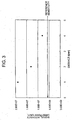
- Fig. 3 shows the measurement result of the change (sensitivity change) of the signal intensity (in arbitrary unit) by the sample ion that is detected when the distance r between the center position of the aperture 12 at the end of the GC column 9 and the axis indicated by one-dot-chain line shown in Figs. 1 and 2 is changed.
- the value 2.00E + 7 represents 2.00 x 10 7 . This also holds true of the expression of the ordinate in Figs. 4 and 7 .
- Fig. 3 shows, as a reference sensitivity, the signal intensity (in arbitrary unit) measured by charging the same sample into the GC column 9, conducting separation, connecting the aperture 12 at the end of the GC column 9 to the primary ion generation gas introduction piping 1 between the mass flow controller 6 and the second ionization portion shown in Fig. 1 , and mixing the separated sample gas flowing out from the aperture 12 at the end of the GC column 9 with the primary ion generation gas that is caused to flow at a rate of 1,000 mL/min through the primary ion generation gas introduction piping 1.
- TCP trichlorophenol
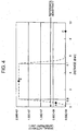
- Fig. 4 shows the change of the signal intensity due to the sample ion detected when the distanced (see Fig. 2 ) of the center position of the aperture 12 at the end of the GC column 9 from the ion inlet of the sample ion introduction aperture 8 is changed.
- the measurement condition is the same as that of Fig. 3 .
- the primary ion generation gas is caused to flow at a flow rate of 1,000 mL/min through the primary ion generation gas introduction piping 1, the primary ion generation gas is exhausted at a flow rate of 350 mL/min from the sample ion introduction aperture 8 and the primary ion generation gas is exhausted at a rate of 650 mL/min from the primary ion introduction aperture 11.
- the sensitivity can be improved 3.2 times at the point B in Fig. 4 .
- the sensitivity is 0.7 times at the point A and is 0.1 times at the point C and is lower than the reference sensitivity.
- the sample gas introduced from the aperture 12 at the end of the GC column 9 is exhausted half and half at the point B shown in Fig. 4 from the primary ion introduction aperture 11 and from the sample ion movement aperture 8. Therefore, the reaction time can be regarded as the mean value of T 8 and T 11 .
- the signal intensity 1E + 9 can be obtained. Though this value does not agree with the experimental value shown in Fig. 4 , the reaction can be regarded as having proceeded sufficiently and got into saturation.
- Fig. 4 shows by dotted line the relation between the distance d and the signal intensity acquired from the result described above. Because the reaction has got into saturation within the range of 0.9 mm ⁇ d ⁇ 5.1 mm, the signal intensity does not rise any more.
- the end 12 of the outlet of the GC column 9 is preferably arranged at the position that satisfies the relation 0.02Q ⁇ Q' ⁇ 0.95Q for the flow rate Q' of the sample gas Q exhausted from the sample ion movement aperture 8.
- reaction time T 8 or T 11 obtained from Expression (4) or (5) becomes sufficiently long and the reaction time in which the primary ion and the sample molecule coexist can be sufficiently extended in the field of the ion-molecule reaction, the generation amount of the sample ion can be increased and the sensitivity can be improved.
- the relation 0.4Q ⁇ Q' ⁇ 0.6Q is substantially satisfied, a similar effect can be obtained.
- Q' ⁇ 0.5Q can be satisfied when the center of the aperture 12 at the end of the GC column 9 is arranged at the intermediate position substantially equidistant from the center of the ion outlet of the primary ion introduction aperture 11 and from the center of the ion inlet of the sample ion movement Aperture 8.
- Q' ⁇ 0.5Q the sample gas introduced from the aperture 12 at the end of the GC column 9 is exhausted with good balance from the primary ion introduction aperture 11 and from the sample ion movement aperture 8.
- the retention time in which the primary ion and the sample molecule coexist in the field of the ion-molecule reaction can be sufficiently extended, the sufficient time for the progress of the ion-molecule reaction can be secured, the generation amount of the sample ion can be increased and the sensitivity can be improved.
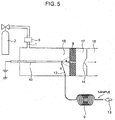
- Fig. 5 is a sectional view showing a construction of a mass spectrometer according to the second embodiment, which is an example useful to understand the invention but not an embodiment of the invention.
- the construction of the second embodiment is effective for executing positive ionization of the sample gas.
- the sample gas introduced from the aperture 12 at the end of the GC column 9 is introduced into a corona discharge portion (area indicated by dotted line in Fig. 2 ).
- the needle electrode 10 is arranged inside the ionization portion 18 and the primary ion generation gas introduction piping 1 is connected at a position far from the sample ion movement aperture 8 (position on the root side of needle electrode 10) on the opposite side to the tip end of the needle electrode 10 inside the ionization portion 18.
- the primary ion generation gas from the gas cylinder 2 is introduced through the primary ion generation gas introduction piping 1 into the ionization portion 18 while its flow rate is regulated by the mass flow controller 6.
- the center of the aperture 12 at the end of the GC column 9 is arranged at a position at which the sample gas from the aperture 12 at the end of the GC column 9 is introduced into the corona discharge portion.
- the center of the aperture 12 at the end of the GC column 9 is preferably arranged at the position satisfying the relation x ⁇ a between the center of the distal end of the needle electrode 10 and the center of the ion inlet of the sample ion movement aperture 8.
- symbol a represents the distance between the center of the tip end of the needle electrode 10 and the center of the ion inlet of the sample ion movement aperture 8 and symbol x represents the distance between the center of the tip end of the needle electrode 10 and the center of the aperture 12 at the end of the GC column 9.
- the primary ion generation gas and the sample gas are exhausted from only the sample ion movement aperture 8. Therefore, the full amount of the primary ion generation gas and the full amount of the sample gas introduced from the aperture 12 at the end of the GC column 9 are exhausted from the sample ion movement aperture 8 to the differential exhaust portion 17. In consequence, the sum of the primary ion generation gas and the introduction amount of the sample gas into the ionization portion 18 is equal to the gas amount exhausted from the sample ion movement aperture 18. Because the sample gas is not exhausted from the ionization portion 18 through exhaust ports other than the ion movement aperture 8, the amount of the sample gas exhausted without reacting with the primary ion becomes small and the sensitivity can be improved.
- the sample gas flow rate introduced from the aperture 12 at the end of the GC column 9 is 4 mL/min and 100% of the sum of the introduction amount of the primary ion generation gas and the introduction amount of the sample gas is exhausted from the sample ion movement aperture 8
- the introduction amount of the primary ion generation gas is 346 mL/min and the dilution ratio of the sample gas inside the ionization portion 18 becomes lower than in the construction shown in Fig. 1 . Therefore, this construction is effective when contamination of the ion source by impurities is small.
- This exhaust port is preferably formed in the wall of the ionization portion 18 in the proximity of the corona discharge portion of the ionization portion 18 and in the proximity of the sample ion movement aperture 8 such as the wall in the direction perpendicular to the needle electrode 10 and intersecting at right angles the partition forming the sample ion movement aperture 8.
- the different exhaust port (not shown) is separately formed from the sample ion movement aperture 8 in the ionization portion 18, at least 80% of the sum of the introduction amount of the primary ion generation gas and that of the sample gas is preferably exhausted from the sample ion movement aperture 8.
- the proportion of the sample gas flowing along the portion near the axis connecting the distal end of the needle electrode and the center of the ion inlet of the sample ion movement aperture 8 at which the primary ion and, the sample gas (molecule) efficiently react with each other occupies at least 80% of the full amount introduced into the ionization portion 18 and the measurement can be carried out while the sensitivity of 80 to 100% is maintained in comparison with the case where the full amount introduced into the ionization portion 18 is caused to flow along the portion near the axis connecting the tip end of the needle electrode 10 and the center of the ion inlet of the sample ion movement aperture 8.
- the tip end of the needle electrode 10, the center of the sample ion movement aperture 8 and the center of the ion introduction aperture 14 are arranged on the same axis but they can be arranged while deviating from one another. When they are arranged in deviation, it is possible to prevent the neutral molecule from mixing into the mass analysis portion 15 and to reduce the noise resulting from the neutral molecule. In either case, the resulting sample ion is introduced into the mass analysis portion 15 through the sample ion movement aperture 8 and the ion introduction aperture 14.
- Fig. 6 is a sectional view showing a construction of a mass spectrometer according to the third embodiment, which is an example useful to understand the invention but not an embodiment of the invention.
- the construction of the third embodiment is effective for executing positive ionization of the sample components having a small reaction rate constant in the ionization reaction.
- the difference of the third embodiment from the first embodiment resides in the arrangement position of the center of the aperture 12 at the end of the GC column 9, the arrangement position of the primary ion generation gas introduction piping 1 and exhausting of the gas from an ion passage aperture 20 in place of the primary ion generation gas exhaust piping 7.
- the sample gas introduced from the aperture 12 at the end of the GC column 9 is introduced into the corona discharge portion (area indicated by dotted line in Fig. 6 ) in the same way as in the second embodiment.
- the ionization portion 18' in which the needle electrode 10 is arranged is connected to an ion movement space (area into which primary ion generation gas is introduced) 19 through the lead-out electrode 4 in which the ion passage aperture 20 is formed.
- the ion movement space 19 is connected to the differential exhaust portion 17 through a partition in which the sample ion movement aperture 8 is formed.
- the primary ion generation gas from the gas cylinder 2 is introduced through the primary ion generation gas introduction piping 1 into the ionization portion 18' at the position opposite to the tip end of the needle electrode 10 and far from the ion passage aperture 20 (position on the root side of needle electrode 10) while its flow rate is regulated by the mass flow controller 6.
- the primary ion generation gas introduced into the ionization portion 18' is introduced into the ion movement space 19 together with the sample gas, the primary ion and the sample ion generated in the ionization portion 18' through the ion passage aperture 20 and is exhausted from the differential exhaust portion 17.
- the center of the aperture 12 at the end of the GC column 9 is arranged at a position at which the sample gas from the aperture 12 at the end of the GC column 9 is introduced into the corona discharge portion.
- the center of the aperture 12 at the end of the GC column 9 is preferably arranged at the position satisfying the relation x ⁇ a between the center of the tip end of the needle electrode 10 and the center of the ion inlet of the ion passage aperture 20.
- symbol a represents the distance between the center of the tip end of the needle electrode 10 and the center of the ion inlet of the ion passage aperture 20 and symbol x represents the distance between the center of the distal end of the needle electrode 10 and the center of the aperture 12 at the end of the GC column 9.
- the relation z ⁇ a is preferably satisfied.
- symbol a represents the distance between the center of the tip end of the needle electrode 10 and the center of the ion inlet of the ion passage aperture 20
- symbol z represents the distance between the center of the ion outlet of the ion passage aperture 20 and the center of the ion inlet of the sample ion movement aperture 8.
- the sample gas introduced into the corona discharge portion passes through the ion passage aperture 20 and is introduced into the ion movement space 19.
- the sample ion is generated by the ion-molecule reaction between the primary ion generated by corona discharge inside the corona discharge portion and the sample molecule.
- the sample ion is also generated by the ion-molecule reaction between the primary ion and the sample gas passing through the ion passage aperture 20.
- At least 80% of the sum of the introduction amount of the primary ion generation gas and that of the sample gas is preferably exhausted from the sample ion movement aperture 8 even when an exhaust port (not shown) is disposed separately from the primary on generation gas exhaust piping 7 in the ionization portion 18' or the ion movement space 19 in the same way as in the second embodiment.
- the proportion of the sample gas flowing along the portion near the axis connecting the tip end of the needle electrode 10 and the center of the ion inlet of the sample ion movement aperture 8 at which the primary ion and the sample gas (molecule) efficiently react with each other occupies at least 80% of the full amount introduced into the ionization portion 18 and the measurement can be carried out while the sensitivity of 80 to 100% is maintained in comparison with the case where the full amount introduced into the ionization portion 18 is caused to flow along the portion near the axis connecting the distal end of the needle electrode 10 and the center of the ion movement aperture 8 in the same way as in the second embodiment.
- the sample gas is directly exhausted from the corona discharge portion to the sample ion movement aperture 8. Therefore, when a sample having a low reaction rate constant in the ionization reaction is ionized, the retention time in which the primary ion and the sample molecule coexist cannot be secured sufficiently and the generation amount of the sample ion cannot be increased.
- the third embodiment having the ion movement space 19 can conduct the analysis at a higher sensitivity than in the second embodiment.
- the tip end of the needle electrode 10, the center of the ion passage aperture 20, the center of the sample ion movement aperture 8 and the center of the ion introduction aperture 14 are arranged on the same axis but they can be arranged while deviating from one another. When they are arranged in deviation, it is possible to prevent the neutral molecule from mixing into the mass analysis portion 15 and to reduce the noise resulting from the neutral molecule. In either case, the resulting sample ion is introduced into the mass analysis portion 15 through the ion passage hole 20, the sample ion movement aperture 8 and the ion introduction aperture 14.
- Fig. 7 shows the measurement result of the change (sensitivity change) of the signal intensity (in arbitrary unit) by the sample ion that is detected when the distance x between the center of the aperture 12 at the end of the GC column 9 and the center of the tip end of the needle electrode 10 is changed.
- the measurement condition is the same as the condition used for obtaining the result shown in Fig. 3 .
- a and z satisfy the relation z ⁇ a.
- the primary ion generation gas is caused to flow at a flow rate of about 350 mL/min through the primary ion generation gas introduction piping 1 and the full amount of the primary ion generation gas and the full amount of the sample gas from the aperture 12 at the end of the GC column 9 are exhausted from the differential exhaust portion 17 through the ion passage aperture 20 and the sample ion movement aperture 8.
- the inner diameter of the sample gas piping may be the same as the inner diameter of the GC column.
- the invention can provide the mass spectrometer (GC/APCI/MS) and the mass spectrometry method that separate the mixed sample by GC, ionize the sample gas so separated by using the APCI source having the construction that does not easily invite contamination and can be applied to mixed samples of a broad application field without being affected by dilution of the sample gas by the primary ion generation gas.
- GC/APCI/MS mass spectrometer
Landscapes
- Chemical & Material Sciences (AREA)
- Analytical Chemistry (AREA)
- Physics & Mathematics (AREA)
- Engineering & Computer Science (AREA)
- Plasma & Fusion (AREA)
- Health & Medical Sciences (AREA)
- Life Sciences & Earth Sciences (AREA)
- Biochemistry (AREA)
- General Health & Medical Sciences (AREA)
- General Physics & Mathematics (AREA)
- Immunology (AREA)
- Pathology (AREA)
- Other Investigation Or Analysis Of Materials By Electrical Means (AREA)
- Electron Tubes For Measurement (AREA)
Description
- This invention relates to an atmospheric pressure chemical ionization mass spectrometry for analyzing a sample gas separated by gas chromatography.
- In the description to follow, gas chromatography will be abbreviated as "GC", a mass spectrometer, as "MS", an apparatus including the combination of the gas chromatography and the mass spectrometer, as "GC/MS", an atmospheric pressure chemical ionization source, as "APCI source", an atmospheric pressure chemical ionization mass spectrometer (apparatus including the combination of APCI and MS), as "APCI/MS", a chemical ionization source, as "CI source", an electron impact ion source, as "EI source", and an apparatus including the combination of the gas chromatography and the atmospheric pressure chemical ionization mass spectrometer, as "GC/APCI/MS".
- GC/MS is a known analytic technology. APCI/MS is an apparatus that ionizes trace components in a mixed sample and detects them with a high level of sensitivity by using an ion-molecule reaction. This apparatus has been utilized for the analysis of the trace components contained in environmental samples and living body samples. A report of a high sensitivity analytical apparatus including the combination of GC and APCI/MS, for analyzing various trace impurities inclusive of semiconductor specific gases (refer to
JP-A-9-15207 JP-A-295269 JP-A-6-310091 - According to
JP-A-9-15207 - According to
JP-A-11-295269 - "The flow rate of the sample gas introduced into APCI/MS is generally from hundreds of mL (milliliters)/min to several L/min. The flow rate of the carrier gas of GC is generally 20 to 50 mL/min. It is therefore necessary to add a corresponding amount of a makeup gas from the makeup passage to the outflow gas from GC. Because this makeup gas dilutes the impurities as the assumed objects, however, its flow rate must be reduced as much as possible. To improve the sensitivity of the impurities in the analysis through GC, therefore, it is preferred to minimize the flow rate of the sample gas introduced into APCI/MS such as about 300 mL/min."
-
JP-A-6-310091 - "... includes an ion generation portion as an area for generating a primary ion, having an introduction port of a primary ion generation gas and ionization means, a sample introduction portion as an area into which the sample gas is introduced, a mixing portion in which the primary ion supplied with the primary ion generation gas from the ion generation portion is mixed with the sample gas and ions of an object material in the sample gas are generated by an ion-molecule reaction, and a mass analysis portion which is held under high vacuum and in which the ion introduced from the mixing portion through an aperture is subjected to mass separation, wherein at least one of means for transporting the ion to the aperture by adding an electric field by an electrode disposed in the mixing portion, means for constituting the ion generation portion and the sample introduction portion into a double wall tube and making the flow of the primary ion generation gas and the flow of the sample gas parallel to each other in the mixing portion, and means for discharging the gas reaching the aperture in a direction extending along a surface having the aperture is added so as to increase a detection ion amount".
- In the column of "prior Art",
JP-A-6-310091 - "The primary ion is injected with the primary ion generation gas under the atmospheric pressure and the primary ion is mixed with the sample gas at the atmospheric pressure ahead of the aperture of the mass analysis portion. The ion of the object material is generated by the ion-molecule reaction. Because the ion generation portion and the sample introduction portion are separated in APCI/MS, the ion generation portion is not contaminated even when a gas flowing out from GC and LC (liquid chromatograph) is used as the sample gas and ionization can be carried out stably for a long time".
- Ionization of the sample gas by chemical ionization in air is well known (refer to "The Journal of Chemical Physics", Vol. 52, 212-221(1970)).
- In
JP-A-9-15207 JP-A-11-295269 JP-A-6-310091 JP-A-6-310091 - The analysis by GC/MS is suitable for separation analysis of a plurality of components contained in a mixed sample, particularly for separation analysis of components having high volatility. The ion source used for GC/MS generally includes a CI source and an EI source. These ion sources are used for ionization under vacuum of about 0.1 torr to several torr. The sample gas separated by GC is introduced into the ion source under this vacuum. However, when the sample contains a large number of impurities, the impurities are adsorbed to the wall of the ion source and to constituent components and remain inside the ion source. Consequently, the ion source is contaminated and an S/N ratio gets decreased. Therefore, maintenance such as frequent cleaning of the ion source is necessary and hinders efficient analysis.
- When the APCI source is used for the ion source, on the other hand, ionization of the sample is conducted at the atmospheric pressure and a differential exhaust portion for transporting the ion from the ion source to the mass analysis portion under vacuum is disposed. The ion from the ion source is introduced into the vacuum portion through an ion introduction aperture having a diameter of about 0.1 to about 0.5 mmφ. To keep stable duration of corona discharge, a gas (primary ion generation gas (discharge gas)) of a flow rate of about 0.1 to about 1 L/min must be caused to flow steadily to the ion source and the gas flow rate flowing through the ion introduction aperture is about 0.1 to about 1 L/min.
- Because the flow rate from GC is several to dozens of mL/min, the gas from GC is diluted by the primary ion generation gas that is caused to flow to the ion source. However, the problem of the drop of sensitivity occurs when the gas from GC is merely mixed with the primary ion generation gas.
-
US 2003/015657 A1 discloses a mass spectrometer related to the one of the present invention. - It is an object of the invention to provide an APCI source not easily contaminated, and a mass spectrometer and a mass spectrometry including the combination of a gas chromatography using this APCI source and capable of high sensitivity analysis without being affected by dilution of a sample gas by a primary ion generation gas with an atmospheric pressure ionization mass spectrometer.
- A typical construction of the mass spectrometer (GC/APCI/MS) according to the invention will be explained. The APCI source includes a first ionization portion for generating a primary ion from a primary ion generation gas by corona discharge generated by a voltage applied to a needle electrode disposed inside the first ionization portion, and a second ionization portion for generating a sample ion by an ion-molecule reaction between the sample gas directly introduced from an end of a GC column and the primary ion sent from the first ionization portion, having an aperture at the end of the GC column disposed therein.
- The sample gas separated in the GC column contains a single component completely separated or a plurality of components not completely separated. The first ionization portion and the second ionization portion are separated from each other by a lead-out electrode having a primary ion introduction aperture through which the primary ion passes. The primary ion generation gas introduced into the second ionization portion passes through the primary ion introduction aperture, flows to the tip end of the needle electrode and is exhausted from the first ionization portion. The sample ion generated in the second ionization portion is introduced into the mass analysis portion through the sample ion movement aperture, the differential exhaust portion and the sample ion introduction aperture and is subjected to mass analysis.
- The sample gas is directly introduced from a position in the proximity of an axis connecting the center of the primary ion introduction aperture through which the primary ion passes and the center of the sample ion movement aperture through which the sample ion moves, into the second ionization portion from the aperture at the end of the GC column. The center of the aperture at the end of the GC column is arranged at the position that is substantially equidistant from the center of an ion outlet of the primary ion introduction aperture and from the center of an ion inlet of the sample ion movement aperture and satisfies the relation r ≦ 2R where R is a radius of the primary ion introduction aperture and r is a distance from the axis connecting the center of the primary ion introduction aperture to the center of the sample ion movement aperture.
- The sample gas that is directly introduced with the carrier gas from the aperture at the end of the GC column into the second ionization portion under the state where it is not diluted flows to the primary ion introduction aperture and to the sample ion movement aperture at substantially the same flow rate along the axis connecting the center of the primary ion introduction aperture to the center of the sample ion movement aperture.
- The retention time in which the primary ion and the sample molecule coexist in the field of the ion-molecule reaction as the field in which the primary ion and the sample molecule react with each other becomes long and a sufficient time for the progress of the ion-molecule reaction can be secured. In consequence, the sample molecule can be efficiently ionized, the generation amount of the sample ion increases and the sensitivity can be improved.
- Because the sample gas flows through the primary ion introduction aperture and the sample ion movement aperture while being diluted by the primary ion generation gas, the APCI source (first ionization portion, second ionization portion, needle electrode, apertures) is not contaminated by the impurities contained in the sample gas and the analysis can be carried out at a high sensitivity without being affected by the impurities.
- The mass spectrometer (GC/APCI/MS) according to the invention can analyze at a high sensitivity the mixed sample containing large amounts of impurities without contamination of the ion source by the impurities.
- The invention can provide an APCI source not generating contamination and a mass spectrometer (GC/APCI/MS) and a mass spectrometry using the APCI source and capable of high sensitivity analysis without being affected by dilution of a sample gas by a primary ion generation gas.
- The invention employs a construction in which a sample gas is directly introduced into the field of an ion-molecule reaction capable of ionization with high efficiency and the resulting sample ion is introduced highly efficiently into a mass analysis portion. Therefore, the invention can prevent the drop of sensitivity due to dilution of the sample gas before its introduction into an ion source and contamination of the ion source, and makes it possible to conduct high sensitivity analysis.
- The mass spectrometer according to preferred embodiments of the invention will be explained in detail with reference to the accompanying drawing.
- Other objects, features and advantages of the invention will become apparent from the following description of the embodiments of the invention taken in conjunction with the accompanying drawings.
-
-
Fig. 1 is a sectional view showing a construction of a mass spectrometer according to a first embodiment of the invention; -
Fig. 2 is a partial enlarged view ofFig. 1 and is an explanatory view showing an arrangement of the center of anaperture 12 at an end of aGC column 9 inside asecond ionization portion 5 and the flow of a gas inside thesecond ionization portion 5; -
Fig. 3 is a diagram showing a measurement result of a change of a signal intensity by a sample ion detected when a distance r between the center of theaperture 12 at the end of theGC column 9 and an axis indicated by one-dot-chain line inFigs. 1 and2 is changed in the construction of the first embodiment; -
Fig. 4 is a diagram showing a measurement result of the change of the signal intensity by the sample ion detected when the distance between the center of theaperture 12 at the end of theGC column 9 and the axis indicated by one-dot-chain line inFigs. 1 and2 is kept constant and the center position of theaperture 12 at the end of theGC column 9 is changed in the direction of the axis indicated by one-dot-chain line inFigs. 1 and2 in the construction of the first embodiment; -
Fig. 5 is a sectional view showing a construction of a mass spectrometer according to a second embodiment, which is an example useful to understand the invention but not an embodiment of the invention; -
Fig. 6 is a sectional view showing a construction of a mass spectrometer according to a third embodiment, which is an example useful to understand the invention but not an embodiment of the invention; and -
Fig. 7 is a diagram showing a measurement result of a change of a signal intensity by a sample ion detected when a distance between the center of theaperture 12 at the end of theGC column 9 and the center of a tip end portion of aneedle electrode 10 is changed in the construction of the third embodiment. -
Fig. 1 is a sectional view showing a construction of a mass spectrometer according to a first embodiment of the invention. This mass spectrometer (GC/APCI/MS) is a high sensitivity apparatus that ionizes sample molecules (sample gas) separated by a GC column by an APCI source and analyzes the mass. - A
first ionization portion 3 and asecond ionization portion 5 are separated from each other by a first partition (lead-out electrode 4) having a primaryion introduction aperture 11 through which a primary ion passes. Thesecond ionization portion 5 is an area that is interposed by the first partition and a second partition that has a sampleion movement aperture 8 through which a sample ion of a sample gas generated by the reaction between the sample molecule and the primary ion (hereinafter called "ion-molecule reaction") inside thesecond ionization portion 5 passes. - The mass spectrometer according to the first embodiment includes the
first ionization portion 3, thesecond ionization portion 5, adifferential exhaust portion 17 and amass analysis portion 15. Thefirst ionization portion 3 and thesecond ionization portion 5 are separated by the lead-outelectrode 4 having the primaryion introduction aperture 11 and thesecond ionization portion 5 and thedifferential exhaust portion 17 are separated by a wall having the sampleion movement aperture 8. Thedifferential exhaust portion 17 and themass analysis portion 11 are separated by a wall having anion introduction aperture 14. The primaryion introduction aperture 11 is an aperture through which the primary ion generated in thefirst ionization portion 3 moves and the sampleion movement aperture 8 is an aperture through which the sample ion generated in thesecond ionization portion 5 moves. Theion introduction aperture 14 is an aperture for introducing the sample ion into themass analysis portion 15. The sample ion moves into themass analysis portion 15 through the sampleion movement aperture 8, thedifferential exhaust portion 17 and theion introduction aperture 14. - The
needle electrode 10 is arranged inside thefirst ionization portion 3 as a corona discharge portion and a primary ion generation gas exhaust piping 7 is connected. The primary ion generation gas exhaust piping 7 is connected to thefirst ionization portion 3 at a position far from the lead-out electrode 4 (position on the root side of needle electrode 10) on the opposite side to the tip end of theneedle electrode 10. - A primary ion generation gas introduction piping 1 for supplying a primary ion generation gas from a
gas cylinder 2 is connected to thesecond ionization portion 5. The primary ion generation gas from thegas cylinder 2 is introduced through the primary ion generation gas introduction piping 1 into thesecond ionization portion 5 while its flow rate is regulated by amass flow controller 6. The primary ion generation gas is preferably the one that does not impedes ionization of the sample gas introduced from theaperture 12 at the end of theGC column 9 into thesecond ionization portion 5, such as air, nitrogen, or helium and argon having low ionization efficiency. A high voltage is applied to theneedle electrode 10 and the primary ion generation gas is ionized due to corona discharge to generate the primary ion. - The primary ion generation gas introduced into the
second ionization portion 5 and the sample gas flow along an axis (indicated by one-dot-chain line inFig. 1 ) connecting the center of the primaryion introduction aperture 11 to the center of the sampleion movement aperture 8 into thefirst ionization portion 3 through the primaryion introduction aperture 11 and into thedifferential exhaust portion 17 through the sampleion movement aperture 8. The primary ion flows also into thesecond ionization portion 5 along the axis indicated by one-dot-chain line inFig. 1 . Therefore, the field of the ion-molecule reaction in which the ion-molecule reaction proceeds is an area in the proximity of the axis in which the primary ion and the sample molecule coexist and which is indicated by one-dot chain line inFig. 1 . - The flow rate of the primary ion generation gas to be introduced into the
second ionization portion 5 is the balance obtained by subtracting the flow rate of the sample gas introduced from theaperture 12 at the end of theGC column 9 into thesecond ionization portion 5 from the sum of the flow rate of the gas exhausted from the primary ion generation gas exhaust piping 7 and the flow rate of the gas flowing out from the sampleion movement aperture 8 into thedifferential exhaust portion 17. Themass flow controller 6 arranged in the primary ion generation gas introduction piping 1 or a mass flow controller (not shown) arranged in the primary ion generation gas exhaust piping 7 regulates the flow rate of the primary ion generation gas. - The sample (mixed sample) is introduced with a
carrier gas 13 into one of the ends (inlet) of theGC column 9 and is separated. A liquid sample is injected into the inlet of theGC column 9 or a gas of components adsorbed to a solid and desorbed by heating is introduced into theGC column 9. Thecarrier gas 13 allowed to flow into theGC column 9 is preferably helium or nitrogen as an inert gas. Preferably, the mass flow controller or a pressure controller (not shown) controls the flow rate of thecarrier gas 13 to a constant flow rate. - The center of the
aperture 12 at the end (other end) of theGC column 9 is arranged in the proximity of the axis indicated by one-dot-chain line inFig. 1 . Because theaperture 12 at the end of theGC column 9 for introducing the sample gas (which flows through the GC column with the carrier gas and contains a single component separated completely or a plurality of components not completely separated) separated by theGC column 9 is arranged in the proximity of the axis indicated by one-dot-chain line inFig. 1 , dilution of the sample as by the primary ion generation gas can be prevented and high sensitivity can be achieved. The detailed explanation of the position at which the center of theaperture 12 at the end of theGC column 9 is arranged will be given later. - To increase the generation amount of the sample ion by the ion-molecule reaction and to accomplish a high sensitivity, it is necessary to secure the field of the ion-molecule reaction as long as possible, to extend the retention time of the coexistence of the primary ion and the sample molecule and to secure the time in which the ion-molecule reaction proceeds. To this end, it is important to introduce the sample gas into the position in the proximity of the axis indicated by one-dot-chain line in
Fig. 1 lest the sample gas introduced from theaperture 12 at the end of theGC column 9 into thesecond ionization portion 5 is diluted by the primary ion generation gas inside thesecond ionization portion 5. - In the
second ionization portion 5, the lead-outelectrode 4 leads out the primary ion, the sample gas is introduced into the position in the proximity of the axis indicated by one-dot-chain line inFig. 1 and the sample ion is generated by the ion-molecule reaction. The sample gas introduced from theaperture 12 at the end of theGC column 9 is diluted inside thesecond ionization portion 5 and is exhausted from the sampleion movement aperture 8 and the primaryion introduction aperture 11. - When the center of the
aperture 12 of theGC column 9 is too close to the sampleion movement aperture 8, the sample gas is exhausted almost fully from the sampleion movement aperture 8. At this time, the retention time in which the primary ion and the sample molecule coexist becomes short in the field of the ion-molecule reaction, a sufficient time for the ion-molecule reaction cannot be secured, the generation amount of the sample ion becomes small and the sensitivity drops. - When the center of the
aperture 12 of theGC column 9 is too close to the primaryion introduction aperture 11, the sample gas is exhausted almost fully from the primaryion introduction aperture 11. At this time, too, the retention time in which the primary ion and the sample molecule coexist becomes short in the field of the ion-molecule reaction, a sufficient time for the ion-molecule reaction cannot be secured, the generation amount of the sample ion becomes small and the sensitivity drops in the same way as described above. - To increase the generation amount of the sample ion and to improve the sensitivity, it is important to secure the retention time in which the primary ion and the sample molecule coexist in the field of the ion-molecule reaction and to secure a sufficient time in which the ion-molecule reaction proceeds. When the center of the
aperture 12 at the end of theGC column 9 is arranged at a position substantially equidistant from the center of the ion outlet of the primaryion introduction aperture 11 and from the center of the ion inlet of the sampleion movement aperture 8, the sample gas introduced from theaperture 12 at the end of theGC column 9 is discharged with good balance from the primaryion introduction aperture 11 and the sampleion movement aperture 8. Consequently, the retention time in which the primary ion and the sample molecule coexist can be extended and the sufficient time for the progress of the ion-molecule reaction can be secured. As a result, the generation amount of the sample ion can be increased and the sensitivity can be improved. The process in which the sample ion is generated will be later explained in detail. - Incidentally, the tip end of the
needle electrode 10, the center of the primaryion introduction aperture 11, the center of the sampleion movement aperture 8 and the center of theion introduction aperture 14 are arranged on the same axis in the construction of the first embodiment but they can be so arranged as to be deviated from one another. When they are arranged in deviation, it is possible to prevent the neutral molecule from mixing into themass analysis portion 15 and to reduce the noise resulting from the neutral molecule. - The sample ion generated at the position in the proximity of the axis indicated by one-dot-chain line in
Fig. 1 inside thesecond ionization portion 5 is caused to flow through the sampleion movement aperture 8 by the potential applied between the sampleion movement aperture 8 and theion introduction aperture 14, is introduced in the direction indicated by arrows into themass analysis portion 15 exhausted to high vacuum by an exhaust system not shown in the drawing through theion introduction aperture 14, and mass analysis of the sample ion is made. Mass spectrometers such as a quadrupole mass spectrometer, an ion trap mass spectrometer, an ion trap TOF (time of-flight) mass spectrometer, magnetic section mass spectrometer, etc, can be applied to themass analysis portion 15. - The primary ion generation gas flowing through the sample
ion movement aperture 8 and the sample gas are exhausted by an exhaust system, not shown, for exhausting thedifferential exhaust portion 17. - When the aperture diameter of the sample
ion movement aperture 8 is 0.25 mmφ and the degree of vacuum is 2 Torr in the construction shown inFig. 1 , thesecond ionization portion 5 is at 760 Torr (atmospheric pressure). Therefore, the flow rate of the gas flowing through the sampleion movement aperture 8 is about 350 mL/min. When the introduction amount of the primary ion generation gas is 1,000 mL/min, the flow rate of the gas flowing out from the primaryion introduction aperture 11 into thefirst ionization portion 3 is about 650 mL/min. - The sample is separated by the
GC column 9 and the sample components so separated are serially introduced with thecarrier gas 13 from theaperture 12 at the end of theGC column 9 into thesecond ionization portion 5. When acapillary GC column 9 having high resolution is used, the flow rate of thecarrier gas 13 is several mL/min and the sample gas from theGC column 9 is introduced to the position in the proximity of the axis indicated by one-dot-chain line inFig. 1 . Therefore, the generation amount of the sample ion can be increased. The sample gas flowing into thesecond ionization portion 5 flows along the axis indicated by one-dot-chain line inFig. 1 and is sufficiently diluted by the primary ion generation gas passing through the primaryion introduction aperture 11. Consequently, the inner wall of thesecond ionization portion 5 is not contaminated by impurities contained in the sample gas. - The outline of the ionization process of the sample gas is as follows. The explanation will be given on the case of positive ionization by way of example. Corona discharge is induced between the
needle electrode 10 to which a high voltage of about +4 kV is applied and the lead-outelectrode 4 to which about +1 kV is applied. When dry air is used for the primary ion generation gas, for example, the primary ion (N2 + or N4 +) is generated by the reaction of the Expression (1) or (2) (refer to the afore-mentioned "The Journal of Chemical Physics", Vol. 52, 212-221 (1970)"):
N2 → N2 ++ e- ... (1)
N2 + + 2N2 → N4 + + N2 ... (2)
- Because the primary
ion introduction aperture 11 having a diameter of about 2 mmφ is formed in the lead-outelectrode 4, the resulting primary ion is introduced by the electric field into thesecond ionization portion 5. The ion of the sample gas (secondary ion: sample ion) is generated inside thesecond ionization portion 5 by the ion-molecule reaction between the primary ion generated by the corona discharge and the sample gas introduced from theaperture 12 at the end of theGC column 9. - The construction of the first embodiment shown in
Fig. 1 is particularly effective when negative ionization of the sample gas is conducted. When negative ionization of the sample gas is conducted by using air for the primary ion generation gas, the primary ion generation gas flows from the needle tip of theneedle electrode 10 towards its root and the reaction between the radical NO* resulting from the corona discharge and the primary ion O2 - can be suppressed. Also, the sensitivity can be improved because O2 - led out to thesecond ionization portion 5 efficiently reacts with the sample gas introduced from theaperture 12 at the end of theGC column 9. -
Fig. 2 is a partial enlarged view ofFig. 1 and explains the center position of theaperture 12 at the end of theGC column 9 and the flow of the gas inside thesecond ionization portion 5. - When the pressure P1 of the
second ionization portion 5 is 760 Torr, the pressure P2 of thedifferential exhaust portion 17 is 2 Torr, the diameter of the sampleion movement aperture 8 is D = 0.25 mmφ and its length is 20 mm, the amount Q8 of the gas that flows into the sampleion movement aperture 8 is about 350 mL/min. The position in the proximity of the axis indicated by one-dot-chain line inFigs. 1 and2 is the area in which the concentration of the primary ion generated by the corona discharge is high and when the sample gas is directly injected into this area, a high sensitivity can be achieved. - The construction satisfies the relation r ≦ 2R where R is the inner diameter (radius) of the primary
ion introduction aperture 11 and r is the distance between the center of theaperture 12 at the end of theGC column 9 and the axis indicated by one-dot-chain line. The center of theaperture 12 at the end of theGC column 9 in the direction of the axis indicated by one-dot-chain line inFigs. 1 and2 is preferably arranged at the position that can extend the coexistence retention time of the primary ion and the sample molecule in the field of the ion-molecule reaction and can secure the sufficient reaction time. - When the center of the
aperture 12 at the end of theGC column 9 is too close to the sampleion movement aperture 8, the sample gas is discharged almost fully from the sampleion movement aperture 8. Because the sample gas is not ionized at this time and is discharged from the primaryion introduction aperture 11, the coexistence retention time of the primary ion and the sample molecule in the field of the ion-molecule reaction becomes short, the sufficient time in which the ion-molecule reaction proceeds cannot be secured, the generation amount of the sample ion decreases and the sensitivity drops in the same way as described above. - When the center of the
aperture 12 at the end of theGC column 9 is too close to the primaryion introduction aperture 11, the sample gas is discharged almost fully from the primaryion introduction aperture 11. At this time, too, because the sample gas is not ionized and is discharged from the primaryion introduction aperture 11, the coexistence retention time of the primary ion and the sample molecule in the field of the ion-molecule reaction becomes short, the sufficient time in which the ion-molecule reaction proceeds cannot be secured, the generation amount of the sample ion decreases and the sensitivity drops in the same way as described above. - In other words, to accomplish the high sensitivity, it is necessary to arrange the center of the
aperture 12 at the end of theGC column 9 at the position at which the sample gas introduced from theaperture 12 at the end of theGC column 9 can be discharged with good balance from the primaryion introduction aperture 11 and from the sampleion movement aperture 8 inside thesecond ionization portion 5. When such a construction is employed, the coexistence retention time of the primary ion and the sample molecule in the field of the ion-molecule reaction can be sufficiently extended, the sufficient time for the progress of the ion-molecule reaction can be secured, too, the generation amount of the sample ion can be increased and the sensitivity can be improved. - Preferably, the position from the axis indicated by one-dot-chain line and the center position of the
aperture 12 at the end of theGC column 9 in the direction of the axis indicated by one-dot-chain line inFigs. 1 and2 are regulated so as to satisfy the relation 0.02Q ≦ Q' ≦ 0.95Q when Q is the flow rate of the sample gas flowing through theaperture 12 at the end of theGC column 9 and Q' is the flow rate of the sample gas Q discharged to thedifferential exhaust portion 17 through the sampleion movement aperture 8. - The number of the sample ions generated by the ion-molecule reaction between the sample molecule and the primary ion can be calculated in accordance with the following expression:

- Here, when the distance d of the center position of the
aperture 12 at the end of the outlet of theGC column 9 from the ion inlet of the sampleion introduction aperture 8 is changed, A, σ and I remain unchanged in the expression (1) and p is constant when the measurement is made under the same sample condition. Therefore, the reaction time T can be estimated in the following way. - A velocity distribution inside the
second ionization portion 5 will be considered on the assumption that no disturbance exists in the proximity of the introduction portion of the primary ion generation gas introduced from the primary ion generation gas introduction piping 1. The flow rate of the sample gas introduced from theaperture 12 at the end of theGC column 9 is by far smaller than the flow rate of the primary ion generation gas introduced from the primary ion generation gas introduction piping 1. Therefore, the influences of the introduction of the sample gas on the flow field are neglected. A flow velocity vector at the position spaced apart by the distance d from the center of the ion inlet of the sampleion movement aperture 8 in the proximity of the axis connecting the center of the ion outlet of the primaryion introduction aperture 11 and the center of the ion inlet of the sampleion movement aperture 8 is the sum of a velocity vector V8 due to the gas flow exhausted from the sample ion movement aperture 8 (direction represents the center of sample ion movement aperture 8) and a speed vector V11 (direction represents the center of sample ion movement aperture 11) due to the gas flow exhausted from the primaryion introduction aperture 11. The magnitudes of the vectors (flow velocity) are expressed by expression (2) and (3).

- Here, Qa and Q11 represent the gas flow rates exhausted from the sample
ion movement aperture 8 and from the primaryion introduction aperture 11, respectively, and L represents the distance between the center of the sampleion movement aperture 8 and the center of the primaryion introduction aperture 11. Expressions (2) and (3) represent that the flow velocity becomes smaller at positions away from the respective exhaust ports (sampleion movement aperture 8 and primary ion introduction aperture 11). - Let's consider the time T till the sample molecule at the position spaced apart by the distance d from the center of the sample
ion movement aperture 8 enters the sampleion movement aperture 8. When the velocity vector V11 is negligibly small in the proximity of the sampleion movement aperture 8, for example, that is, when d is smaller than L, only V8 may be taken into consideration as the flow velocity. The time T8 (reaction time) till the sample molecule introduced from theaperture 12 at the end of the outlet of theGC column 9 enters the sampleion movement aperture 8 is calculated intoexpression 4 by integrating the expression (2).
- Similarly, when the position of the sample molecule is close to the primary
ion introduction aperture 11 and d is close to L, only V11 may be taken into consideration as the flow velocity and the reaction time T11 is calculated into expression (5) by integrating the expression (3).
- To increase the number of sample ions expressed by expression (1), that is, to improve the sensitivity, the
aperture 12 at the end of the outlet of theGC column 9 is preferably arranged at the position that increases the reaction time T8 or T11. -
Fig. 3 shows the measurement result of the change (sensitivity change) of the signal intensity (in arbitrary unit) by the sample ion that is detected when the distance r between the center position of theaperture 12 at the end of theGC column 9 and the axis indicated by one-dot-chain line shown inFigs. 1 and2 is changed. In the expression of the ordinate inFig. 3 , the value 2.00E + 7 represents 2.00 x 10⁷. This also holds true of the expression of the ordinate inFigs. 4 and7 . - Under the measurement condition shown in
Fig. 3 , measurement is conducted by charging 1 µL of a toluene solution of trichlorophenol (TCP) having a concentration of 1 ppm as a sample into theGC column 9, setting a carrier gas flow rate to 5 mL/min and measuring positive ions by using an ion trap type mass spectrometer. For comparison,Fig. 3 shows, as a reference sensitivity, the signal intensity (in arbitrary unit) measured by charging the same sample into theGC column 9, conducting separation, connecting theaperture 12 at the end of theGC column 9 to the primary ion generation gas introduction piping 1 between themass flow controller 6 and the second ionization portion shown inFig. 1 , and mixing the separated sample gas flowing out from theaperture 12 at the end of theGC column 9 with the primary ion generation gas that is caused to flow at a rate of 1,000 mL/min through the primary ion generation gas introduction piping 1. - The sensitivity can be improved 3.2 times, 2.2 times and 1.3 times at r = 1 mm, 2 mm and 4 mm, respectively, in comparison with the reference sensitivity. It can be understood from this result that the sensitivity becomes lower as the distance r between the center of the
aperture 12 at the end of theGC column 9 and the axis indicated by one-dot-chain line shown inFigs. 1 and2 becomes greater. It can be understood also from the result shown inFig. 3 that the signal intensities (in arbitrary unit) measured at r = 1 mm, 2 mm and 4 mm satisfying the relation r ≦ 2R = 4 mm with respect to the inner diameter of the primary ion introduction aperture 11 (radius R = 2 nim (2R = 4 mm)) is greater than the reference sensitivity. It has been confirmed that when r ≦ 2R, the sensitivity can be made higher than when the measurement is conducted by merely connecting theaperture 12 at the end of theGC column 9 to the primary ion generation gas introduction piping 1 and mixing the separated sample gas flowing out from theaperture 12 at the end of theGC column 9 with the primary ion generation gas. -
Fig. 4 shows the measurement result of the change (sensitivity change) of the signal intensity (in arbitrary unit) by.the sample ion detected when the center position of theaperture 12 at the end of theGC column 9 is changed in the direction of the axis indicated by one-dot-chain line while the distance between the center of theaperture 12 at the end of theGC column 9 and the axis indicated by one-dot-chain line inFigs. 1 and2 is kept constant at r = 1 mm. In other words,Fig. 4 shows the change of the signal intensity due to the sample ion detected when the distanced (seeFig. 2 ) of the center position of theaperture 12 at the end of theGC column 9 from the ion inlet of the sampleion introduction aperture 8 is changed. The measurement condition is the same as that ofFig. 3 . - The primary ion generation gas is caused to flow at a flow rate of 1,000 mL/min through the primary ion generation gas introduction piping 1, the primary ion generation gas is exhausted at a flow rate of 350 mL/min from the sample
ion introduction aperture 8 and the primary ion generation gas is exhausted at a rate of 650 mL/min from the primaryion introduction aperture 11. - The point A shown in
Fig. 4 represents the signal intensity (in arbitrary unit) due to the sample ion detected when the center position of theaperture 12 at the end of theGC column 9 is arranged extremely close to the sampleion movement aperture 8 and the distance is set to d = 0.5 mm. When d = 0.5 mm, the sample gas flowing out from theaperture 12 at the end of theGC column 9 is almost fully introduced into the sampleion movement aperture 8. - The point B shown in
Fig. 4 represents the signal intensity (in arbitrary unit) due to the sample ion detected when the center position of theaperture 12 at the end of theGC column 9 is arranged at the intermediate position substantially equidistant from the center of the ion output of the primaryion introduction aperture 11 and from the center of the ion inlet of the sampleion movement aperture 8 and the distance is set to d = 3 mm. When d = 3 mm, about a half of the flow rate of the sample gas flowing out from theaperture 12 at the end of theGC column 9 is exhausted from the sampleion introduction aperture 8 and the flow rate of the remaining gas is exhausted from the primaryion introduction aperture 11. - The point C in
Fig. 4 represents the signal intensity (in arbitrary unit) by the sample ion detected at d = 9 mm when the center of theaperture 12 at the end of theGC column 9 is arranged at a position inside thefirst ionization portion 3 between the center of the primaryion introduction aperture 11 and the center of the distal end of theneedle electrode 10. When d = 9 mm, the flow rate of the sample gas flowing though theaperture 12 at the end of theGC column 9 is exhausted substantially fully from the primary ion generation gas exhaust piping 7. In comparison with the reference sensitivity, the sensitivity can be improved 3.2 times at the point B inFig. 4 . The sensitivity is 0.7 times at the point A and is 0.1 times at the point C and is lower than the reference sensitivity. It has been confirmed from this result that the higher sensitivity than the reference sensitivity can be obtained when the center of theaperture 12 at the end of theGC column 9 is arranged at the intermediate position substantially equidistant from the center of the ion outlet of the primaryion introduction aperture 11 and from the center of the ion inlet of the referenceion movement aperture 8.
- Here, the point A shown in
Fig. 4 is close to the sampleion movement aperture 8 and the following Expression (7) can be assumed.
- When the condition of the point A (d = 0.5 mm, Q8 = 350 mL/min, signal intensity = 4E + 6) is put, A' = 8.0
E + 9. Because the sensitivity at the point A (d = 0.5 mm) is 0.7 times the reference sensitivity, the position at which the sensitivity equal to the reference sensitivity is obtained is given as d = 0.6 mm from Expressions (6) and (7). - Similarly, the position close to the primary
ion introduction aperture 11 at which the sensitivity equal to the reference sensitivity is obtained is given as d = 5.4 mm by putting L = 6 mm, Q11 = 650 mL/min and A = 8.0E + 9 into (6) by regarding Expression (6) as (8) :
- The sample gas introduced from the
aperture 12 at the end of theGC column 9 is exhausted half and half at the point B shown inFig. 4 from the primaryion introduction aperture 11 and from the sampleion movement aperture 8. Therefore, the reaction time can be regarded as the mean value of T8 and T11. When d = 3 mm is put into Expressions (6), (7) and (8), the signal intensity = 1E + 9 can be obtained. Though this value does not agree with the experimental value shown inFig. 4 , the reaction can be regarded as having proceeded sufficiently and got into saturation. -
Fig. 4 shows by dotted line the relation between the distance d and the signal intensity acquired from the result described above. Because the reaction has got into saturation within the range of 0.9 mm ≦ d ≦ 5.1 mm, the signal intensity does not rise any more. - The flow velocity ratio obtained from the velocity vectors V8 and V11 when the position of the
aperture 12 at the end of the outlet of theGC column 9 is arranged at d = 0.9 mm is V8:V11 ≈ 18:1. Assuming that the flow rate Q of the gas introduced from theaperture 12 at the end of the outlet of theGC column 9 is distributed in accordance with this flow velocity ratio and is exhausted from the sampleion movement aperture 8 and from the primaryion introduction aperture 11, the flow rate Q' exhausted from the sample ion movement aperture is given by Q' ≈ 0.95Q. Similarly, when theaperture 12 is arranged at d = 5.1 mm, Q' is given by Q' = 0.02Q. - To sum up, the
end 12 of the outlet of theGC column 9 is preferably arranged at the position that satisfies the relation 0.02Q ≦ Q' ≦ 0.95Q for the flow rate Q' of the sample gas Q exhausted from the sampleion movement aperture 8. - Particularly when sample components having a small collision cross section and a long reaction time till saturation are ionized, regulation is made so that Q' becomes substantially equal to about 0.5Q. The equation Q' = 0.5Q can be satisfied when the center of the
aperture 12 at the end of theGC column 9 is arranged at the intermediate position substantially equidistant from the center of the ion outlet of the primaryion introduction aperture 11 and from the center of the ion inlet of the sampleion movement aperture 8, more accurately at the position at which the flow velocity V8 is substantially equal to the flow velocity V11 obtained from Expressions (2) and (3). In this case, the reaction time T8 or T11 obtained from Expression (4) or (5) becomes sufficiently long and the reaction time in which the primary ion and the sample molecule coexist can be sufficiently extended in the field of the ion-molecule reaction, the generation amount of the sample ion can be increased and the sensitivity can be improved. Incidentally, when the relation 0.4Q ≦ Q' ≦ 0.6Q is substantially satisfied, a similar effect can be obtained. - In other words, Q' ≈ 0.5Q can be satisfied when the center of the
aperture 12 at the end of theGC column 9 is arranged at the intermediate position substantially equidistant from the center of the ion outlet of the primaryion introduction aperture 11 and from the center of the ion inlet of the sampleion movement Aperture 8. When Q' ≈ 0.5Q is satisfied, the sample gas introduced from theaperture 12 at the end of theGC column 9 is exhausted with good balance from the primaryion introduction aperture 11 and from the sampleion movement aperture 8. Consequently, the retention time in which the primary ion and the sample molecule coexist in the field of the ion-molecule reaction can be sufficiently extended, the sufficient time for the progress of the ion-molecule reaction can be secured, the generation amount of the sample ion can be increased and the sensitivity can be improved. -
Fig. 5 is a sectional view showing a construction of a mass spectrometer according to the second embodiment, which is an example useful to understand the invention but not an embodiment of the invention. The construction of the second embodiment is effective for executing positive ionization of the sample gas. - In the second embodiment, the sample gas introduced from the
aperture 12 at the end of theGC column 9 is introduced into a corona discharge portion (area indicated by dotted line inFig. 2 ). Theneedle electrode 10 is arranged inside theionization portion 18 and the primary ion generation gas introduction piping 1 is connected at a position far from the sample ion movement aperture 8 (position on the root side of needle electrode 10) on the opposite side to the tip end of theneedle electrode 10 inside theionization portion 18. The primary ion generation gas from thegas cylinder 2 is introduced through the primary ion generation gas introduction piping 1 into theionization portion 18 while its flow rate is regulated by themass flow controller 6. - In the second embodiment, the center of the
aperture 12 at the end of theGC column 9 is arranged at a position at which the sample gas from theaperture 12 at the end of theGC column 9 is introduced into the corona discharge portion. When theaperture 12 at the end of theGC column 9 is disposed at this time inside the corona discharge portion, corona discharge cannot be induced stably or the resulting sample ion adheres to theaperture 12 at the end of the GC column to lower the sensitivity. Therefore, the center of theaperture 12 at the end of theGC column 9 is preferably arranged at the position satisfying the relation x ≧ a between the center of the distal end of theneedle electrode 10 and the center of the ion inlet of the sampleion movement aperture 8. Here, symbol a represents the distance between the center of the tip end of theneedle electrode 10 and the center of the ion inlet of the sampleion movement aperture 8 and symbol x represents the distance between the center of the tip end of theneedle electrode 10 and the center of theaperture 12 at the end of theGC column 9. - In the second embodiment, the primary ion generation gas and the sample gas are exhausted from only the sample
ion movement aperture 8. Therefore, the full amount of the primary ion generation gas and the full amount of the sample gas introduced from theaperture 12 at the end of theGC column 9 are exhausted from the sampleion movement aperture 8 to thedifferential exhaust portion 17. In consequence, the sum of the primary ion generation gas and the introduction amount of the sample gas into theionization portion 18 is equal to the gas amount exhausted from the sampleion movement aperture 18. Because the sample gas is not exhausted from theionization portion 18 through exhaust ports other than theion movement aperture 8, the amount of the sample gas exhausted without reacting with the primary ion becomes small and the sensitivity can be improved. - Assuming that the gas flow rate passing through the sample
ion movement aperture 8 is 350 mL/min, the sample gas flow rate introduced from theaperture 12 at the end of theGC column 9 is 4 mL/min and 100% of the sum of the introduction amount of the primary ion generation gas and the introduction amount of the sample gas is exhausted from the sampleion movement aperture 8, the introduction amount of the primary ion generation gas is 346 mL/min and the dilution ratio of the sample gas inside theionization portion 18 becomes lower than in the construction shown inFig. 1 . Therefore, this construction is effective when contamination of the ion source by impurities is small. - To reduce contamination by the impurities inside the
ionization portion 18, it is advisable to increase the flow rate of the primary ion generation gas and to dilute the sample gas in the proximity of the corona discharge portion. To conduct measurement while the internal pressure of theionization portion 18 is kept at the atmospheric pressure, however, it is necessary to exhaust the mixed gas of the primary ion generation gas and the sample gas from theionization portion 18 in the amount corresponding to the increment of the flow rate of the primary ion generation gas through an exhaust port separately from the sampleion movement aperture 8. This exhaust port is preferably formed in the wall of theionization portion 18 in the proximity of the corona discharge portion of theionization portion 18 and in the proximity of the sampleion movement aperture 8 such as the wall in the direction perpendicular to theneedle electrode 10 and intersecting at right angles the partition forming the sampleion movement aperture 8. When the flow rate of the primary ion generation gas is increased, however, the proportion of the sample gas that is diluted by the primary ion generation gas increases and the sensitivity drops. - Therefore, when the different exhaust port (not shown) is separately formed from the sample
ion movement aperture 8 in theionization portion 18, at least 80% of the sum of the introduction amount of the primary ion generation gas and that of the sample gas is preferably exhausted from the sampleion movement aperture 8. - Under such a condition, the proportion of the sample gas flowing along the portion near the axis connecting the distal end of the needle electrode and the center of the ion inlet of the sample
ion movement aperture 8 at which the primary ion and, the sample gas (molecule) efficiently react with each other occupies at least 80% of the full amount introduced into theionization portion 18 and the measurement can be carried out while the sensitivity of 80 to 100% is maintained in comparison with the case where the full amount introduced into theionization portion 18 is caused to flow along the portion near the axis connecting the tip end of theneedle electrode 10 and the center of the ion inlet of the sampleion movement aperture 8. - In the construction of the second embodiment, the tip end of the
needle electrode 10, the center of the sampleion movement aperture 8 and the center of theion introduction aperture 14 are arranged on the same axis but they can be arranged while deviating from one another. When they are arranged in deviation, it is possible to prevent the neutral molecule from mixing into themass analysis portion 15 and to reduce the noise resulting from the neutral molecule. In either case, the resulting sample ion is introduced into themass analysis portion 15 through the sampleion movement aperture 8 and theion introduction aperture 14. -
Fig. 6 is a sectional view showing a construction of a mass spectrometer according to the third embodiment, which is an example useful to understand the invention but not an embodiment of the invention. The construction of the third embodiment is effective for executing positive ionization of the sample components having a small reaction rate constant in the ionization reaction. - The difference of the third embodiment from the first embodiment resides in the arrangement position of the center of the
aperture 12 at the end of theGC column 9, the arrangement position of the primary ion generation gas introduction piping 1 and exhausting of the gas from anion passage aperture 20 in place of the primary ion generation gas exhaust piping 7. In the third embodiment, the sample gas introduced from theaperture 12 at the end of theGC column 9 is introduced into the corona discharge portion (area indicated by dotted line inFig. 6 ) in the same way as in the second embodiment. - The ionization portion 18' in which the
needle electrode 10 is arranged is connected to an ion movement space (area into which primary ion generation gas is introduced) 19 through the lead-outelectrode 4 in which theion passage aperture 20 is formed. Theion movement space 19 is connected to thedifferential exhaust portion 17 through a partition in which the sampleion movement aperture 8 is formed. The primary ion generation gas from thegas cylinder 2 is introduced through the primary ion generation gas introduction piping 1 into the ionization portion 18' at the position opposite to the tip end of theneedle electrode 10 and far from the ion passage aperture 20 (position on the root side of needle electrode 10) while its flow rate is regulated by themass flow controller 6. The primary ion generation gas introduced into the ionization portion 18' is introduced into theion movement space 19 together with the sample gas, the primary ion and the sample ion generated in the ionization portion 18' through theion passage aperture 20 and is exhausted from thedifferential exhaust portion 17. - In the third embodiment, the center of the
aperture 12 at the end of theGC column 9 is arranged at a position at which the sample gas from theaperture 12 at the end of theGC column 9 is introduced into the corona discharge portion. When theaperture 12 at the end of theGC column 9 is disposed at this time inside the corona discharge portion, corona discharge cannot be induced stably or the resulting sample ion adheres to theaperture 12 at the end of the GC column to lower the sensitivity. Therefore, the center of theaperture 12 at the end of theGC column 9 is preferably arranged at the position satisfying the relation x ≧ a between the center of the tip end of theneedle electrode 10 and the center of the ion inlet of theion passage aperture 20. Here, symbol a represents the distance between the center of the tip end of theneedle electrode 10 and the center of the ion inlet of theion passage aperture 20 and symbol x represents the distance between the center of the distal end of theneedle electrode 10 and the center of theaperture 12 at the end of theGC column 9. - To secure a longer retention time in which the primary ion and the sample molecule coexist, the relation z ≧ a is preferably satisfied. Here, symbol a represents the distance between the center of the tip end of the
needle electrode 10 and the center of the ion inlet of theion passage aperture 20 and symbol z represents the distance between the center of the ion outlet of theion passage aperture 20 and the center of the ion inlet of the sampleion movement aperture 8. - The sample gas introduced into the corona discharge portion passes through the
ion passage aperture 20 and is introduced into theion movement space 19. The sample ion is generated by the ion-molecule reaction between the primary ion generated by corona discharge inside the corona discharge portion and the sample molecule. The sample ion is also generated by the ion-molecule reaction between the primary ion and the sample gas passing through theion passage aperture 20. As a result, the retention time for the coexistence of the primary ion and the sample molecule can be secured in both corona discharge portion andion movement space 19, the sufficient time for the progress of the ion-molecule reaction can be secured, the generation amount of the sample ion can be increased and the sensitivity can be improved. - In the third embodiment, at least 80% of the sum of the introduction amount of the primary ion generation gas and that of the sample gas is preferably exhausted from the sample
ion movement aperture 8 even when an exhaust port (not shown) is disposed separately from the primary on generation gas exhaust piping 7 in the ionization portion 18' or theion movement space 19 in the same way as in the second embodiment. - Under such a condition, the proportion of the sample gas flowing along the portion near the axis connecting the tip end of the
needle electrode 10 and the center of the ion inlet of the sampleion movement aperture 8 at which the primary ion and the sample gas (molecule) efficiently react with each other occupies at least 80% of the full amount introduced into theionization portion 18 and the measurement can be carried out while the sensitivity of 80 to 100% is maintained in comparison with the case where the full amount introduced into theionization portion 18 is caused to flow along the portion near the axis connecting the distal end of theneedle electrode 10 and the center of theion movement aperture 8 in the same way as in the second embodiment. - In the second embodiment shown in
Fig. 5 , the sample gas is directly exhausted from the corona discharge portion to the sampleion movement aperture 8. Therefore, when a sample having a low reaction rate constant in the ionization reaction is ionized, the retention time in which the primary ion and the sample molecule coexist cannot be secured sufficiently and the generation amount of the sample ion cannot be increased. In this case, the third embodiment having theion movement space 19 can conduct the analysis at a higher sensitivity than in the second embodiment. - In the construction of the third embodiment, the tip end of the
needle electrode 10, the center of theion passage aperture 20, the center of the sampleion movement aperture 8 and the center of theion introduction aperture 14 are arranged on the same axis but they can be arranged while deviating from one another. When they are arranged in deviation, it is possible to prevent the neutral molecule from mixing into themass analysis portion 15 and to reduce the noise resulting from the neutral molecule. In either case, the resulting sample ion is introduced into themass analysis portion 15 through theion passage hole 20, the sampleion movement aperture 8 and theion introduction aperture 14. -
Fig. 7 shows the measurement result of the change (sensitivity change) of the signal intensity (in arbitrary unit) by the sample ion that is detected when the distance x between the center of theaperture 12 at the end of theGC column 9 and the center of the tip end of theneedle electrode 10 is changed. The measurement condition is the same as the condition used for obtaining the result shown inFig. 3 . - The distance a between the center of the tip end of the
needle electrode 10 and the center of the ion inlet of theion passage aperture 20 is a = 3.5 mm, the distance z between the center of the ion outlet of theion passage aperture 20 and the center of the ion inlet of the sampleion movement aperture 8 is z = 6 mm, and a and z satisfy the relation z ≧ a. The primary ion generation gas is caused to flow at a flow rate of about 350 mL/min through the primary ion generation gas introduction piping 1 and the full amount of the primary ion generation gas and the full amount of the sample gas from theaperture 12 at the end of theGC column 9 are exhausted from thedifferential exhaust portion 17 through theion passage aperture 20 and the sampleion movement aperture 8. - The sensitivity at x = 2 mm when x ≦ a is 0.7 times the reference sensitivity and is lower than the reference sensitivity but the sensitivity at x = 4 mm when x ≧ a is trice the reference sensitivity.
- Incidentally, it is possible to connect the outlet at the other end opposite to one end (inlet) of the
GC column 9 through which the sample (mixed sample) is introduced with thecarrier gas 13 to one of the ends of the sample gas piping and to use the outlet at the other end of this sample gas piping in place of theaperture 12 at the end of theGC column 9 in the first, second and third embodiments. - In other words, it is possible in the embodiment shown in
Figs. 1 and2 to connect the other end of the GC column and thesecond ionization portion 5 by the sample gas piping, to arrange the outlet at the other end of the sample gas piping to the center position of theaperture 12 at the other end of theGC column 9 shown inFigs. 1 and2 , to connect the other end of theGC column 9 and theionization portion 18, 18' by the sample gas piping in the embodiment shown inFig. 5 and in the third embodiment shown inFig. 6 , and to arrange the outlet at the other end of the sample gas piping to the center position of theaperture 12 at the end of theGC column 9 shown inFigs. 5 and6 . In these constructions, the inner diameter of the sample gas piping may be the same as the inner diameter of the GC column. - The invention can provide the mass spectrometer (GC/APCI/MS) and the mass spectrometry method that separate the mixed sample by GC, ionize the sample gas so separated by using the APCI source having the construction that does not easily invite contamination and can be applied to mixed samples of a broad application field without being affected by dilution of the sample gas by the primary ion generation gas.
- It should be further understood by those skilled in the art that although the foregoing description has been made on an embodiment of the invention, the invention is not limited thereto and various changes and modifications may be made without departing from the scope of the appended claims.
Claims (5)
- A mass spectrometer comprising:an atmospheric pressure chemical ionization (APCI) source including:(at) a first ionization portion (3) including a needle electrode (10) to which a voltage for corona discharge is to be applied, and an exhaust aperture (7) for a primary ion generation gas, for generating a primary ion from said primary ion generation gas by discharge of said needle electrode (10) ;(a2) a primary ion introduction aperture (11) through which said primary ion is to flow; and(a3) a second ionization portion (5) including an introduction aperture (11) of said primary ion generation gas, for generating a sample ion of a sample gas by the reaction between said primary ion introduced from said primary ion introduction aperture (11) and said sample gas introduced from an end (12) of a column (9) of gas chromatography, said second ionization portion (5) having the end of said column (9) arranged therein;(b) a sample ion movement aperture (8) through which said sample ion is to move; and(c) a mass analysis portion (15) for conducting mass analysis of said sample ion; wherein:said exhaust aperture (7) is arranged at a portion on the opposite side to the tip end of said needle electrode (10), said primary ion generation gas introduced into said second ionization portion (5) being caused to flow to said exhaust aperture (7) from the distal end of said needle electrode (10) through said primary ion introduction aperture (11), andthe end of the column (9) is arranged at a position satisfying the relation

- A mass spectrometer as defined in claim 1, which satisfies the relation 0.02Q ≤ Q' ≤ 0.95Q, where Q is the flow rate of said sample gas at the end of said column (9) and Q' is the flow rate of said sample gas introduced into said second ionization portion (5) and exhausted from said sample ion movement aperture (8).
- A mass spectrometer as defined in claim 1, which satisfies the relation 0.4Q ≤ Q' ≤ 0.6Q, where Q is the flow rate of said sample gas at the end of said column (9) and Q' is the flow rate of said sample gas introduced into said second ionization portion (5) and exhausted from said sample ion movement aperture (8).
- A mass spectrometer as defined in claim 1, which includes a sample gas piping connected to the end of said column (9), and wherein the end of said sample gas piping is arranged inside said second ionization portion (5) in place of the end of said column (9) disposed inside said second ionization portion (5).
- A mass spectrometer as defined in claim 1, wherein said sample ion moving in said sample ion movement aperture (8) is to be introduced into said mass analysis portion (15) through a differential exhaust portion (17).
Applications Claiming Priority (1)
| Application Number | Priority Date | Filing Date | Title |
|---|---|---|---|
| JP2004269112A JP4492267B2 (en) | 2004-09-16 | 2004-09-16 | Mass spectrometer |
Publications (3)
| Publication Number | Publication Date |
|---|---|
| EP1638132A2 EP1638132A2 (en) | 2006-03-22 |
| EP1638132A3 EP1638132A3 (en) | 2007-03-14 |
| EP1638132B1 true EP1638132B1 (en) | 2016-02-17 |
Family
ID=35509336
Family Applications (1)
| Application Number | Title | Priority Date | Filing Date |
|---|---|---|---|
| EP05004827.1A Expired - Fee Related EP1638132B1 (en) | 2004-09-16 | 2005-03-04 | Mass chromatography |
Country Status (3)
| Country | Link |
|---|---|
| US (1) | US7064320B2 (en) |
| EP (1) | EP1638132B1 (en) |
| JP (1) | JP4492267B2 (en) |
Families Citing this family (38)
| Publication number | Priority date | Publication date | Assignee | Title |
|---|---|---|---|---|
| US7138626B1 (en) | 2005-05-05 | 2006-11-21 | Eai Corporation | Method and device for non-contact sampling and detection |
| US7568401B1 (en) | 2005-06-20 | 2009-08-04 | Science Applications International Corporation | Sample tube holder |
| US7576322B2 (en) * | 2005-11-08 | 2009-08-18 | Science Applications International Corporation | Non-contact detector system with plasma ion source |
| JP4982087B2 (en) | 2006-02-08 | 2012-07-25 | 株式会社日立製作所 | Mass spectrometer and mass spectrometry method |
| JP4823794B2 (en) * | 2006-07-24 | 2011-11-24 | 株式会社日立製作所 | Mass spectrometer and detection method |
| US8123396B1 (en) | 2007-05-16 | 2012-02-28 | Science Applications International Corporation | Method and means for precision mixing |
| US8008617B1 (en) | 2007-12-28 | 2011-08-30 | Science Applications International Corporation | Ion transfer device |
| US8227750B1 (en) * | 2008-04-28 | 2012-07-24 | Bruker-Michrom, Inc. | Method and apparatus for nano-capillary/micro electrospray for use in liquid chromatography-mass spectrometry |
| EP2294600A1 (en) * | 2008-05-30 | 2011-03-16 | Thermo Finnigan LLC | Method and apparatus for generation of reagent ions in a mass spectrometer |
| US8071957B1 (en) | 2009-03-10 | 2011-12-06 | Science Applications International Corporation | Soft chemical ionization source |
| JP5622751B2 (en) | 2010-01-25 | 2014-11-12 | 株式会社日立ハイテクノロジーズ | Mass spectrometer |
| JP5596402B2 (en) * | 2010-04-19 | 2014-09-24 | 株式会社日立ハイテクノロジーズ | Analysis device, ionization device, and analysis method |
| JP5711372B2 (en) * | 2010-08-19 | 2015-04-30 | レコ コーポレイションLeco Corporation | Mass spectrometer with soft ionization glow discharge and regulator |
| US8319194B2 (en) | 2010-08-25 | 2012-11-27 | Hitachi High-Technologies Corporation | Drug detection equipment |
| JP5497615B2 (en) | 2010-11-08 | 2014-05-21 | 株式会社日立ハイテクノロジーズ | Mass spectrometer |
| JP6025406B2 (en) | 2012-06-04 | 2016-11-16 | 株式会社日立ハイテクノロジーズ | Mass spectrometer |
| CN103940899B (en) * | 2014-03-21 | 2019-03-29 | 东华理工大学 | A kind of rapid detection method and device of trace explosive |
| KR101934663B1 (en) | 2015-03-06 | 2019-01-02 | 마이크로매스 유케이 리미티드 | An inlet instrument device for an ion analyzer coupled to a rapid evaporation ionization mass spectrometry (" REIMS ") device |
| US11289320B2 (en) | 2015-03-06 | 2022-03-29 | Micromass Uk Limited | Tissue analysis by mass spectrometry or ion mobility spectrometry |
| US11367605B2 (en) | 2015-03-06 | 2022-06-21 | Micromass Uk Limited | Ambient ionization mass spectrometry imaging platform for direct mapping from bulk tissue |
| CN107530065A (en) | 2015-03-06 | 2018-01-02 | 英国质谱公司 | In vivo Microendoscopic tissue identification instrument |
| WO2016142686A1 (en) | 2015-03-06 | 2016-09-15 | Micromass Uk Limited | Liquid trap or separator for electrosurgical applications |
| EP4257967A3 (en) | 2015-03-06 | 2024-03-27 | Micromass UK Limited | Collision surface for improved ionisation |
| US10978284B2 (en) | 2015-03-06 | 2021-04-13 | Micromass Uk Limited | Imaging guided ambient ionisation mass spectrometry |
| CN107580675B (en) | 2015-03-06 | 2020-12-08 | 英国质谱公司 | Rapid evaporative ionization mass spectrometry ("REIMS") and desorption electrospray ionization mass spectrometry ("DESI-MS") analysis of swab and biopsy samples |
| US11031222B2 (en) | 2015-03-06 | 2021-06-08 | Micromass Uk Limited | Chemically guided ambient ionisation mass spectrometry |
| US10777398B2 (en) | 2015-03-06 | 2020-09-15 | Micromass Uk Limited | Spectrometric analysis |
| DE202016008460U1 (en) | 2015-03-06 | 2018-01-22 | Micromass Uk Limited | Cell population analysis |
| WO2016142683A1 (en) | 2015-03-06 | 2016-09-15 | Micromass Uk Limited | Improved ionisation of gaseous samples |
| WO2016142681A1 (en) | 2015-03-06 | 2016-09-15 | Micromass Uk Limited | Spectrometric analysis of microbes |
| CN108700590B (en) | 2015-03-06 | 2021-03-02 | 英国质谱公司 | Cell population analysis |
| CN105181785A (en) * | 2015-03-19 | 2015-12-23 | 南昌大学 | Method for rapid discrimination of Cinnamomun camphcra of different chemotypes |
| GB201517195D0 (en) | 2015-09-29 | 2015-11-11 | Micromass Ltd | Capacitively coupled reims technique and optically transparent counter electrode |
| WO2017178833A1 (en) | 2016-04-14 | 2017-10-19 | Micromass Uk Limited | Spectrometric analysis of plants |
| JP6767037B2 (en) * | 2016-07-28 | 2020-10-14 | 国立大学法人静岡大学 | Isotope measuring device and isotope measuring method |
| US11482405B2 (en) * | 2018-04-05 | 2022-10-25 | Shimadzu Corporation | Mass spectrometry device and mass spectrometry method |
| WO2021171936A1 (en) * | 2020-02-25 | 2021-09-02 | 株式会社バイオクロマト | Ionization device, mass spectroscopy system, and ionization method |
| CN114864373B (en) * | 2022-04-25 | 2023-08-11 | 苏州大学 | Corona discharge ion source |
Family Cites Families (10)
| Publication number | Priority date | Publication date | Assignee | Title |
|---|---|---|---|---|
| JPH0550648U (en) * | 1991-11-27 | 1993-07-02 | 株式会社日立製作所 | Mass spectrometer |
| JPH06310091A (en) * | 1993-04-26 | 1994-11-04 | Hitachi Ltd | Atmospheric pressure ionization mass spectrometer |
| JPH0915207A (en) | 1995-06-29 | 1997-01-17 | Osaka Oxygen Ind Ltd | High-sensitivity analytical device for gas |
| JP3607997B2 (en) | 1998-04-09 | 2005-01-05 | 大陽日酸株式会社 | Analyzer for trace impurities in gas |
| EP1093151B1 (en) * | 1999-09-20 | 2010-09-01 | Hitachi, Ltd. | Ion source, mass spectrometer, mass spectrometry, and monitoring system |
| JP4054493B2 (en) | 1999-09-20 | 2008-02-27 | 株式会社日立製作所 | Ion source |
| JP2001351569A (en) * | 2000-06-02 | 2001-12-21 | Hitachi Ltd | On-line monitor for measuring gas |
| JP3660279B2 (en) * | 2001-07-23 | 2005-06-15 | 株式会社日立製作所 | Sample ionizer and mass spectrometer |
| JP3787116B2 (en) * | 2002-11-06 | 2006-06-21 | 株式会社日立製作所 | How to detect chemical agents |
| JP2004157057A (en) * | 2002-11-08 | 2004-06-03 | Hitachi Ltd | Mass analyzing apparatus |
-
2004
- 2004-09-16 JP JP2004269112A patent/JP4492267B2/en active Active
-
2005
- 2005-03-04 US US11/071,345 patent/US7064320B2/en active Active
- 2005-03-04 EP EP05004827.1A patent/EP1638132B1/en not_active Expired - Fee Related
Also Published As
| Publication number | Publication date |
|---|---|
| EP1638132A3 (en) | 2007-03-14 |
| EP1638132A2 (en) | 2006-03-22 |
| JP4492267B2 (en) | 2010-06-30 |
| US7064320B2 (en) | 2006-06-20 |
| US20060054806A1 (en) | 2006-03-16 |
| JP2006086002A (en) | 2006-03-30 |
Similar Documents
| Publication | Publication Date | Title |
|---|---|---|
| EP1638132B1 (en) | Mass chromatography | |
| US6797947B2 (en) | Internal introduction of lock masses in mass spectrometer systems | |
| US7741600B2 (en) | Apparatus and method for providing ions to a mass analyzer | |
| US10290482B1 (en) | Tandem collision/reaction cell for inductively coupled plasma-mass spectrometry (ICP-MS) | |
| US10090140B2 (en) | IRMS sample introduction system and method | |
| US8324565B2 (en) | Ion funnel for mass spectrometry | |
| US7564029B2 (en) | Sample ionization at above-vacuum pressures | |
| US20040051038A1 (en) | Ion guide | |
| EP2086000A2 (en) | Methods and Apparatus for Reducing Noise in Mass Spectrometry | |
| US9305758B2 (en) | Interface for mass spectrometry apparatus | |
| US8884217B2 (en) | Multimode cells and methods of using them | |
| US10126265B2 (en) | Perturbation ion mobility mass spectrometry and the method of measuring ion mobility of selected ions | |
| US8299428B2 (en) | Detectors and ion sources | |
| JP2000243347A (en) | Ion trap type mass spectrometer and ion trap mass spectrometry | |
| US9048078B2 (en) | Mass spectrometry | |
| KR102215830B1 (en) | Systems and methods for using gas mixtures to select ions | |
| US11239068B2 (en) | Inductively coupled plasma mass spectrometer with mass correction | |
| US20210351028A1 (en) | Quadrupole mass spectrometer | |
| CN110277299B (en) | Series collision/reaction tank for inductively coupled plasma mass spectrometry | |
| US20240162027A1 (en) | System and Method for Variable FFT Analysis Windows in Mass Spectrometry | |
| US6956206B2 (en) | Negative ion atmospheric pressure ionization and selected ion mass spectrometry using a 63NI electron source | |
| JPH0770301B2 (en) | Mass spectrometer |
Legal Events
| Date | Code | Title | Description |
|---|---|---|---|
| PUAI | Public reference made under article 153(3) epc to a published international application that has entered the european phase |
Free format text: ORIGINAL CODE: 0009012 |
|
| AK | Designated contracting states |
Kind code of ref document: A2 Designated state(s): AT BE BG CH CY CZ DE DK EE ES FI FR GB GR HU IE IS IT LI LT LU MC NL PL PT RO SE SI SK TR |
|
| AX | Request for extension of the european patent |
Extension state: AL BA HR LV MK YU |
|
| 17P | Request for examination filed |
Effective date: 20060331 |
|
| PUAL | Search report despatched |
Free format text: ORIGINAL CODE: 0009013 |
|
| AK | Designated contracting states |
Kind code of ref document: A3 Designated state(s): AT BE BG CH CY CZ DE DK EE ES FI FR GB GR HU IE IS IT LI LT LU MC NL PL PT RO SE SI SK TR |
|
| AX | Request for extension of the european patent |
Extension state: AL BA HR LV MK YU |
|
| AKX | Designation fees paid |
Designated state(s): DE FR GB |
|
| 17Q | First examination report despatched |
Effective date: 20120131 |
|
| GRAP | Despatch of communication of intention to grant a patent |
Free format text: ORIGINAL CODE: EPIDOSNIGR1 |
|
| RIC1 | Information provided on ipc code assigned before grant |
Ipc: H01J 49/04 20060101AFI20150619BHEP Ipc: H01J 49/14 20060101ALI20150619BHEP |
|
| INTG | Intention to grant announced |
Effective date: 20150710 |
|
| GRAS | Grant fee paid |
Free format text: ORIGINAL CODE: EPIDOSNIGR3 |
|
| INTG | Intention to grant announced |
Effective date: 20151208 |
|
| GRAA | (expected) grant |
Free format text: ORIGINAL CODE: 0009210 |
|
| AK | Designated contracting states |
Kind code of ref document: B1 Designated state(s): DE FR GB |
|
| REG | Reference to a national code |
Ref country code: GB Ref legal event code: FG4D |
|
| REG | Reference to a national code |
Ref country code: FR Ref legal event code: PLFP Year of fee payment: 12 |
|
| REG | Reference to a national code |
Ref country code: DE Ref legal event code: R096 Ref document number: 602005048448 Country of ref document: DE |
|
| REG | Reference to a national code |
Ref country code: DE Ref legal event code: R097 Ref document number: 602005048448 Country of ref document: DE |
|
| PLBE | No opposition filed within time limit |
Free format text: ORIGINAL CODE: 0009261 |
|
| STAA | Information on the status of an ep patent application or granted ep patent |
Free format text: STATUS: NO OPPOSITION FILED WITHIN TIME LIMIT |
|
| 26N | No opposition filed |
Effective date: 20161118 |
|
| REG | Reference to a national code |
Ref country code: FR Ref legal event code: PLFP Year of fee payment: 13 |
|
| REG | Reference to a national code |
Ref country code: FR Ref legal event code: PLFP Year of fee payment: 14 |
|
| PGFP | Annual fee paid to national office [announced via postgrant information from national office to epo] |
Ref country code: DE Payment date: 20200218 Year of fee payment: 16 Ref country code: GB Payment date: 20200226 Year of fee payment: 16 |
|
| PGFP | Annual fee paid to national office [announced via postgrant information from national office to epo] |
Ref country code: FR Payment date: 20200214 Year of fee payment: 16 |
|
| REG | Reference to a national code |
Ref country code: DE Ref legal event code: R119 Ref document number: 602005048448 Country of ref document: DE |
|
| GBPC | Gb: european patent ceased through non-payment of renewal fee |
Effective date: 20210304 |
|
| PG25 | Lapsed in a contracting state [announced via postgrant information from national office to epo] |
Ref country code: DE Free format text: LAPSE BECAUSE OF NON-PAYMENT OF DUE FEES Effective date: 20211001 Ref country code: FR Free format text: LAPSE BECAUSE OF NON-PAYMENT OF DUE FEES Effective date: 20210331 Ref country code: GB Free format text: LAPSE BECAUSE OF NON-PAYMENT OF DUE FEES Effective date: 20210304 |