EP1637897A2 - Method for determining the identity of a battery pack - Google Patents
Method for determining the identity of a battery pack Download PDFInfo
- Publication number
- EP1637897A2 EP1637897A2 EP05022309A EP05022309A EP1637897A2 EP 1637897 A2 EP1637897 A2 EP 1637897A2 EP 05022309 A EP05022309 A EP 05022309A EP 05022309 A EP05022309 A EP 05022309A EP 1637897 A2 EP1637897 A2 EP 1637897A2
- Authority
- EP
- European Patent Office
- Prior art keywords
- battery pack
- voltage
- battery
- capacitor
- circuit
- Prior art date
- Legal status (The legal status is an assumption and is not a legal conclusion. Google has not performed a legal analysis and makes no representation as to the accuracy of the status listed.)
- Withdrawn
Links
Images


Classifications
-
- H—ELECTRICITY
- H01—ELECTRIC ELEMENTS
- H01M—PROCESSES OR MEANS, e.g. BATTERIES, FOR THE DIRECT CONVERSION OF CHEMICAL ENERGY INTO ELECTRICAL ENERGY
- H01M10/00—Secondary cells; Manufacture thereof
- H01M10/42—Methods or arrangements for servicing or maintenance of secondary cells or secondary half-cells
- H01M10/44—Methods for charging or discharging
- H01M10/441—Methods for charging or discharging for several batteries or cells simultaneously or sequentially
-
- G—PHYSICS
- G01—MEASURING; TESTING
- G01R—MEASURING ELECTRIC VARIABLES; MEASURING MAGNETIC VARIABLES
- G01R31/00—Arrangements for testing electric properties; Arrangements for locating electric faults; Arrangements for electrical testing characterised by what is being tested not provided for elsewhere
- G01R31/36—Arrangements for testing, measuring or monitoring the electrical condition of accumulators or electric batteries, e.g. capacity or state of charge [SoC]
- G01R31/378—Arrangements for testing, measuring or monitoring the electrical condition of accumulators or electric batteries, e.g. capacity or state of charge [SoC] specially adapted for the type of battery or accumulator
-
- H—ELECTRICITY
- H01—ELECTRIC ELEMENTS
- H01M—PROCESSES OR MEANS, e.g. BATTERIES, FOR THE DIRECT CONVERSION OF CHEMICAL ENERGY INTO ELECTRICAL ENERGY
- H01M10/00—Secondary cells; Manufacture thereof
- H01M10/42—Methods or arrangements for servicing or maintenance of secondary cells or secondary half-cells
- H01M10/44—Methods for charging or discharging
- H01M10/443—Methods for charging or discharging in response to temperature
-
- H—ELECTRICITY
- H01—ELECTRIC ELEMENTS
- H01M—PROCESSES OR MEANS, e.g. BATTERIES, FOR THE DIRECT CONVERSION OF CHEMICAL ENERGY INTO ELECTRICAL ENERGY
- H01M10/00—Secondary cells; Manufacture thereof
- H01M10/42—Methods or arrangements for servicing or maintenance of secondary cells or secondary half-cells
- H01M10/46—Accumulators structurally combined with charging apparatus
-
- H—ELECTRICITY
- H01—ELECTRIC ELEMENTS
- H01M—PROCESSES OR MEANS, e.g. BATTERIES, FOR THE DIRECT CONVERSION OF CHEMICAL ENERGY INTO ELECTRICAL ENERGY
- H01M10/00—Secondary cells; Manufacture thereof
- H01M10/42—Methods or arrangements for servicing or maintenance of secondary cells or secondary half-cells
- H01M10/48—Accumulators combined with arrangements for measuring, testing or indicating the condition of cells, e.g. the level or density of the electrolyte
- H01M10/486—Accumulators combined with arrangements for measuring, testing or indicating the condition of cells, e.g. the level or density of the electrolyte for measuring temperature
-
- H—ELECTRICITY
- H02—GENERATION; CONVERSION OR DISTRIBUTION OF ELECTRIC POWER
- H02J—ELECTRIC POWER NETWORKS; CIRCUIT ARRANGEMENTS OR SYSTEMS FOR SUPPLYING OR DISTRIBUTING ELECTRIC POWER; SYSTEMS FOR STORING ELECTRIC ENERGY
- H02J7/00—Circuit arrangements for charging or discharging batteries or for supplying loads from batteries
- H02J7/40—Circuit arrangements for charging or discharging batteries or for supplying loads from batteries characterised by the exchange of charge or discharge related data
- H02J7/443—Circuit arrangements for charging or discharging batteries or for supplying loads from batteries characterised by the exchange of charge or discharge related data using passive battery identification means, e.g. resistors or capacitors
-
- H—ELECTRICITY
- H02—GENERATION; CONVERSION OR DISTRIBUTION OF ELECTRIC POWER
- H02J—ELECTRIC POWER NETWORKS; CIRCUIT ARRANGEMENTS OR SYSTEMS FOR SUPPLYING OR DISTRIBUTING ELECTRIC POWER; SYSTEMS FOR STORING ELECTRIC ENERGY
- H02J7/00—Circuit arrangements for charging or discharging batteries or for supplying loads from batteries
- H02J7/485—Circuit arrangements for charging or discharging batteries or for supplying loads from batteries with provisions for charging different types of batteries
-
- H—ELECTRICITY
- H02—GENERATION; CONVERSION OR DISTRIBUTION OF ELECTRIC POWER
- H02J—ELECTRIC POWER NETWORKS; CIRCUIT ARRANGEMENTS OR SYSTEMS FOR SUPPLYING OR DISTRIBUTING ELECTRIC POWER; SYSTEMS FOR STORING ELECTRIC ENERGY
- H02J7/00—Circuit arrangements for charging or discharging batteries or for supplying loads from batteries
- H02J7/90—Regulation of charging or discharging current or voltage
- H02J7/971—Regulation of charging or discharging current or voltage the charge cycle being controlled or terminated in response to non-electric parameters
- H02J7/975—Regulation of charging or discharging current or voltage the charge cycle being controlled or terminated in response to non-electric parameters in response to temperature
- H02J7/977—Regulation of charging or discharging current or voltage the charge cycle being controlled or terminated in response to non-electric parameters in response to temperature of the battery
-
- H—ELECTRICITY
- H01—ELECTRIC ELEMENTS
- H01M—PROCESSES OR MEANS, e.g. BATTERIES, FOR THE DIRECT CONVERSION OF CHEMICAL ENERGY INTO ELECTRICAL ENERGY
- H01M10/00—Secondary cells; Manufacture thereof
- H01M10/42—Methods or arrangements for servicing or maintenance of secondary cells or secondary half-cells
- H01M10/4221—Methods or arrangements for servicing or maintenance of secondary cells or secondary half-cells with battery type recognition
-
- H—ELECTRICITY
- H02—GENERATION; CONVERSION OR DISTRIBUTION OF ELECTRIC POWER
- H02J—ELECTRIC POWER NETWORKS; CIRCUIT ARRANGEMENTS OR SYSTEMS FOR SUPPLYING OR DISTRIBUTING ELECTRIC POWER; SYSTEMS FOR STORING ELECTRIC ENERGY
- H02J7/00—Circuit arrangements for charging or discharging batteries or for supplying loads from batteries
- H02J7/34—Parallel operation in networks using both storage and other DC sources, e.g. providing buffering
- H02J7/345—Parallel operation in networks using both storage and other DC sources, e.g. providing buffering using capacitors as storage or buffering devices
-
- Y—GENERAL TAGGING OF NEW TECHNOLOGICAL DEVELOPMENTS; GENERAL TAGGING OF CROSS-SECTIONAL TECHNOLOGIES SPANNING OVER SEVERAL SECTIONS OF THE IPC; TECHNICAL SUBJECTS COVERED BY FORMER USPC CROSS-REFERENCE ART COLLECTIONS [XRACs] AND DIGESTS
- Y02—TECHNOLOGIES OR APPLICATIONS FOR MITIGATION OR ADAPTATION AGAINST CLIMATE CHANGE
- Y02E—REDUCTION OF GREENHOUSE GAS [GHG] EMISSIONS, RELATED TO ENERGY GENERATION, TRANSMISSION OR DISTRIBUTION
- Y02E60/00—Enabling technologies; Technologies with a potential or indirect contribution to GHG emissions mitigation
- Y02E60/10—Energy storage using batteries
Definitions
- This invention relates generally to a battery charger monitor that monitors battery pack parameters during charging of a battery and, more particularly, to a battery charger monitor that monitors battery voltage, battery temperature and determines battery pack identification using an identification capacitor within the battery pack, where the battery pack identification and the battery temperature are monitored on a single line between the battery monitor and the battery pack.
- 4,388,582 and 4,392,101 both issued to Sar et al., and assigned to the assignee of the present invention, disclose a quick battery charging technique which monitors the charging of a battery pack by noting inflection points in a voltage charging curve as the electrical chemical potential within the battery cells changes with respect to time. By determining specific inflection points in the charging curve, it is possible to accurately terminate the charging when the battery pack is at full charge.
- the battery monitor may also determine other pieces of useful information, including battery pack temperature and battery pack identification.
- Monitoring battery pack temperature is useful because overheating the battery pack during charging can cause significant damage to the battery pack. Determining the battery pack identification is desirable to ascertain certain things such as maximum battery voltage and capacity, battery chemistry, manufacturing date, etc. This information can be used by a charging control algorithm controlling the charging process to aid in monitoring and adjusting the charging process.
- the prescaler circuit allows the battery charger to effectively monitor the battery voltage for a wide range of battery packs having varying voltages.
- U.S. Patent Application Serial No. 08/834,375 also discloses a technique for monitoring battery temperature using a similar analog-to-digital conversion method.
- U.S. Patent No. 5,489,834 issued to Pitkanen discloses a battery type and temperature identification circuit.
- the battery pack being charged includes a negative temperature coefficient resistor, a voltage divider resistor, and a fixed identification resistor electrically connected in a voltage divider circuit.
- the identification resistor is different for each different battery pack type, and provides the basis for determining battery type.
- An output voltage from the voltage divider circuit follows a particular curve set by the identification resistor as the temperature on the pack changes.
- the identification resistor is selected based on the battery pack type, and the values of the negative temperature coefficient resistor and voltage divider resistor are selected to be the same or nearly the same for each battery type, the different voltage curves at the output of the voltage divider circuit for the different battery types can be spaced apart. By determining which curve the output voltage follows for changes in temperature gives an indication of the battery pack identification.
- German Patent Application No. DE 42 25 686 A1 published March 3, 1994 discloses a circuit for recognizing and charging a battery pack, where the battery pack includes a temperature dependent resistor and an identification capacitor.
- a microprocessor applies a DC voltage signal to the battery pack to determine the resistive value of the temperature dependent resistor.
- a square wave signal is applied to the battery pack, and the impedance is measured.
- What is needed is a battery charger monitor circuit that is able to charge a battery pack in the charger, monitor the voltage of the battery, monitor the temperature of the battery, and provide an indication of the battery pack identification in and efficient and cost effective manner, and doesn't suffer the drawbacks of the prior art devices discussed above. It is therefore, an object of the present invention to provide such a battery monitor circuit.
- a method of determining the identity of a battery pack comprising the steps of:
- a battery monitor uses a thermistor in combination with an AC circuit component (i.e. one that exhibits a recactance), such as a capacitor or an inductor, to determine battery pack temperature and battery pack identification.
- an AC circuit component i.e. one that exhibits a recactance
- the resistance of the thermistor is measured when the battery pack circuit is in a steady-state condition.
- an AC signal is applied to the battery pack circuit under a cynamic circuit condition to identify the AC circuit component and identify the battery pack.
- the temperature of the battery pack and the identification of the battery pack can be determined on a single line.
- a first voltage divider network including a reference capacitor, where an output voltage of the first voltage divider network is applied to one terminal of a comparator.
- a second voltage divider network is provided that is electrically connected to the battery pack.
- the second voltage divider network includes a thermistor positioned within the battery pack at a location suitable to take battery pack temperature measurements, and a plurality of resistors within the battery monitor circuit. The output of the second voltage divider network is applied to another terminal of the comparator.
- the resistive value of the thermistor can be determined based on the output of the comparator. This resistive value is representative of the temperature within the battery pack.
- the second voltage divider network and the comparator are also used to determine battery pack identification.
- An unknown identification capacitor that has a value unique to a particular battery pack is included in the battery pack, and is connected in circuit with the thermistor and the second voltage divider network.
- the battery monitor circuit can determine the capacitance value of the identification capacitor based on its discharge rate.
- One terminal of the comparator is switched to a low reference voltage potential once the identification capacitor has been charged and is at a steady state.
- the second voltage divider network includes a low value resistor that allows the identification capacitor to be quickly discharged. Once the voltage potential of the second divider network applied to the positive terminal of the comparator falls below the reference potential, the monitor can determine the value of the capacitor based on the known value of the resistances.
- the identification of the battery pack is determined by whether a thermistor and a capacitor exist in the battery pack circuit. To determine whether the thermistor is in the battery pack circuit, a voltage output of a voltage divider network is measured. If the measurement indicates that the thermistor does exist, then the voltage measurement is used to determine the resistance of the thermistor. To determine whether the capacitor exists in the battery pack circuit, the capacitor is first discharged, assuming that it does exist. Next, charging of the capacitor is initiated, and after a predetermined period of time, a voltage output of the battery pack circuit is measured to determine whether it is above or below a predetermined threshold value. If it is above the threshold value, then the capacitor does not exist, and if it is below the threshold the capacitor does exist.
- FIG. 1 shows a schematic diagram of a battery monitoring circuit 10 that is separated into a battery pack side 12 and a battery charger side 14, according to an embodiment of the present invention.
- the battery pack side 12 is electrically connected to the battery charger side 14 at three connections 16, 18 and 20, as shown.
- the battery monitor circuit 10 is used to monitor a battery pack 22 including a plurality of battery cells 24.
- the battery monitoring circuit 10 provides three major functions, including monitoring the charging process of the battery pack 22, determining the temperature of the battery pack 22, and identifying the battery pack 22.
- the connection 16 connects a battery pack voltage measuring and charging line
- the connection 18 connects a battery pack temperature and battery pack identification line
- the connection 20 provides a ground connection.
- the battery monitoring circuit 10 will include battery charging circuitry in association with the monitoring circuitry on the battery charger side 14.
- the battery pack identification can provide various desirable information, including battery chemistry, such as nickel cadmium, metal hydride, lithium, etc., number of cells 14, manufacturing date, rated voltage, etc.
- the battery monitoring circuit 10 is microprocessor controlled by a microprocessor 26.
- the microprocessor 26 can be any suitable microprocessor for the purposes described herein, and as will be well understood by those in the art, many different microprocessors are available for this purpose.
- Four of the microprocessor pins are labeled 1, 2, 3 and 4 for purposes of the discussion herein. However, these pins will have different pin numbers depending on which microprocessor is used. As will be discussed in greater detail below, the battery pack temperature and the battery pack identification are both determined from a single connection at pin 2.
- the battery pack side 12 includes a battery pack circuit 30 in electrical connection with the battery pack 22.
- the battery pack circuit 30 includes an identification capacitor 32 and a thermistor 34.
- the thermistor 34 is a variable resistor that changes its resistance based on temperature, as is well understood in the art. Other types of temperature sensing devices may be applicable within the scope of the present invention, as would be appreciated by those skilled in the art.
- the identification capacitor 32 is specially selected to identify the battery pack 22, and thus has a different capacitive value depending upon the pack 22.
- the thermistor 34 is strategically placed within the battery pack 22 so as to provide a temperature reading of the pack 22. Thus, everything on the battery pack side 12 is removable from the actual battery charger as a single unit, and can be replaced with other battery packs.
- both the temperature of the battery pack 22 and the identification of the battery pack 22 are determined through a single connection to the battery charger side 14, here connection 18.
- the temperature of the battery pack 22 is measured when the battery pack circuit 30 is in a steady-state condition, where a DC signal is applied through the connection 18.
- the battery pack circuit 30 is put under a dynamic circuit condition to determine the value of the capacitor 32.
- the capacitor 32 can be replaced with another AC circuit component, such as an inductor.
- the battery charger side 14 of the battery monitoring circuit 10 includes a voltage attenuator 36 or prescaler circuit (resistor divider network) that is used to attenuate the output voltage of the battery pack 12 to be at or near a desirable voltage output.
- the attenuation of the voltage attenuator 36 can be selectively set so that the desirable voltage output is nearly the same for all battery packs 22 regardless of its actual voltage.
- This attenuated voltage is applied to the positive terminal of a comparator 38 at pin 1 of the microprocessor 26.
- the charging voltage applied to the battery pack 22 is applied through the connection 16 from a current source (not shown) to charge the battery pack 22.
- the battery charger side 14 of the battery monitor circuit 10 further includes an RC circuit 40.
- the RC circuit 40 includes a reference capacitor 42 having a known value, and resistors R 1 and R 2 also having known values that make up a voltage divider network within the circuit 40.
- the output voltage of the RC circuit 40 is applied to pin 4 of the microprocessor 26.
- the microprocessor 26 switches a switch 44 to a suitable reference potential, here a plus five volt potential, the capacitor 42 is charged through the resistor R 2 .
- the switch 44 is switched to a high impedance state, and the voltage of the capacitor 42 dissipates through the resistor R 1 at a known dissipation rate based on the values of the capacitor 42 and the resistors R 1 and R 2 .
- This capacitor dissipation voltage is applied to the negative (inverting) terminal of the comparator 38 through a switch 46.
- the microprocessor 26 begins counting at a predetermined clock pulse rate by an internal timer. Once the voltage potential of the capacitor 42 falls below the attenuated voltage of the battery pack 12, the output V out of the comparator 38 goes high, and the microprocessor 26 stores the number of counts.
- Resistors R 3 , R 4 and R 5 and the thermistor 34 make up a voltage divider network 48.
- the switch 44 is connected to the five volt reference potential to charge the capacitor 42, and pins 2 and 3 are set to a high impedance input state, i.e., open, so that the identification capacitor 32 on the battery pack side 12 is charged through the resistor R 3 .
- the thermistor 34 and the resistor R 4 are connected in parallel, and combine with the resistor R 3 to form the voltage divider network 48.
- the output of the voltage divider network 48 at pin 2 is now a function of the temperature of the battery pack 22.
- FIG. 2 A graph of this voltage divider output is shown in Figure 2, where the voltage output at pin 2 is on the vertical axis and temperature is on the horizontal axis. As is apparent, as the temperature increases, the resistance of the thermistor 34 goes down and the voltage divider output at pin 2 decreases.
- the analog voltage divider output at pin 2 is applied to the positive (noninverting) terminal of a comparator 50.
- the voltage signal from the RC circuit 40 is applied to pin 4 of the microprocessor 26, which in turn is applied to the negative (inverting) input terminal of the comparator 50 through the switch 46.
- the capacitor 42 is charged, and the switch 44 is switched to a high impedance state, the capacitor 42 begins to discharge, and the microprocessor 26 begins to count clock pulses.
- the comparator 50 switches high and the microprocessor 26 stores the count pulse as a digital conversion. This count pulse is a digital representation of the temperature.
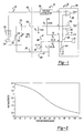
- Figure 3 is a graph showing the voltage divider output at pin 2 in Log AD counts on the vertical axis and temperature on the horizontal axis. As is apparent, as the temperature goes up, the resistance of the thermistor goes down, the voltage output goes down and the digital count decreases.
- the comparators 38 and 50 and the switches 44 and 46 are shown internal to the microprocessor 26. This configuration is shown by way of a non-limiting example in that these components can be external to the microprocessor 26, and the outputs of the comparators 38 and 50 can be applied as inputs to the microprocessor 26. Further, the comparison between the various signals discussed above, and switching of the switches can be performed in software by programming the microprocessor 26. The depiction shown in Figure 1 is solely intended to give an understanding of the basic operation of the monitoring circuit 10 of the invention.
- the identification of the battery pack 22 is also determined at pin 2 of the microprocessor 26.
- pin 2 is set to a high impedance input state and pin 3 is set to a high output state by switching a switch 52 to a +5 volt potential.
- the thermistor 34 and the resistor R 4 are in parallel, and the resistor R 3 and R 5 are in parallel in the voltage divider circuit 48.
- the capacitor 32 is charged through the voltage divider circuit 48 by the high output state potential applied to the resistor R 3 and R 5 .
- a low reference voltage, here 0.2 volts, is applied to the negative terminal of the comparator 50 through the switch 46, and an internal timer of the microprocessor 26 is initialized.
- the capacitor 32 is discharged by setting pin 3 to a low output state by switching the switch 52 to ground and the internal timer is started.
- the charging and discharging of the capacitor 32 provides a changing or dynamic circuit electrical condition.
- the resistor R 5 has a much lower value than the thermistor 34 and the resistors R 3 and R 4 , the capacitor 32 discharges quickly through the resistor R 5 .
- the changing resistance of the thermistor 34 as the temperature changes does not have a significant effect on the discharge rate of the capacitor 32.
- the resistor R 5 has a value that is two magnitudes lower than the resistors R 3 and R 4 to provide this quick discharge.
- this is by way of a non-limiting example in that other values may be applicable for different designs.
- the comparator 50 switches high, and the timed count is stored. This count value represents a voltage discharge time of the capacitor 32. Because the values of R 3 , R 4 , R 5 and the thermistor 34 are known, the value of the capacitor 32 can be determined based on its discharge rate. Because different values for different capacitors will have different discharge times for the same resistor values, by inserting a known capacitor in association with the battery pack 22, the battery pack 22 can be identified.
- the values of the resistors R 3 and R 4 and the thermistor 34 are selected so that the voltage drop across the thermistor 34 falls within the common mode input voltage range of the comparator 50 and within the predicted temperature range of interest. However, these values are not optimized for measuring the voltage decay across the capacitor 32 due to a large temperature dependency. This is apparent by viewing the graph shown in Figure 4, depicting the decay times versus temperature for different values of the capacitor 32 without the resistor R 5 . This shows that without the lower value resistor R 5 , the temperature change on the thermistor 34 has a great effect on the discharge time of a capacitor having different values. Without the resistor R 5 , the process would consume a large amount of software resources when modeled as a microcontroller program, although it would work.
- the decay time temperature dependency can be dramatically reduced by the addition of the resistor R 5 .
- one terminal of the resistor R 5 can be set high when the resistors R 3 and R 5 are in parallel, or set low when the thermistor 34 and resistors R 4 and R 5 are in parallel to dynamically alter the output of the voltage divider circuit 48.
- the voltage divider circuit 48 is optimized for temperature readings. By making the resistor R 5 small in comparison to the thermistor 34, and by setting pin 3 high or low, the voltage divider circuit 48 is optimized for measuring the discharge time of the capacitor 32.
- the resistor R 5 Because the value of the resistor R 5 is small, it "overrides” the effects of the other resistances in the voltage divider circuit 48, including the thermistor 34. This fast charging and discharging through the resistor R 5 results in a capacitor decay time temperature independence as shown in the graph of Figure 5.
- FIG. 6 shows a schematic diagram of a battery monitoring circuit 60 that is separated into a battery pack side 62 and a battery charger side 64, according to another embodiment of the present invention.
- the battery pack side 62 is electrically connected to the battery charger side 64 at three separate connections 66, 68 and 70, as shown.
- the battery monitoring circuit 60 is used to monitor a battery pack 72 that includes a plurality of battery cells 74.
- the connection 66 connects a battery pack voltage measuring and charging line
- the connection 68 connects a battery pack temperature and battery pack identification line
- the connection 70 provides a ground connection.
- the battery monitoring circuit 60 is microprocessor controlled by a microprocessor 76.
- the microprocessor 76 can be any suitable microprocessor for the purposes described herein, such as the Zilog Z86C83, known to those skilled in the art.
- Five of the microprocessor pins are labeled 1, 2, 3, 4 and 5 for purposes of discussion herein. However, these pins will have different pin numbers depending on which microprocessor is used.
- the battery pack 72 is charged by a control signal applied to pin 1 to turn on a current source 78.
- the voltage of the battery pack 72 is measured at pin 2 of the microprocessor 76 using a 12-bit log A/D converter 80 in the same manner as described above.
- the details of the charging and charge monitoring of the battery pack 72 can be any suitable technique known in the art consistent with the battery monitoring circuit 60.
- the battery pack side 62 includes an identification capacitor 82 and a thermistor 84, just as with the embodiment described above.
- the monitoring circuit 60 does not identify the battery pack 72 by determining the actual capacitance of the capacitor 82, but determines the identity of the battery pack 70 by whether the capacitor 82 exists, regardless of its value, and whether the thermistor 84 exists.
- the temperature of the pack may not need to be determined, or may be determined by indirect thermal sensing or other thermal sensing techniques, and thus the thermistor 84 is not needed. Since the identification capacitor 82 only has the purpose of determining the identity of the battery pack 72, the capacitor 82 can also be eliminated.
- both the thermistor 84 and the capacitor 82 can be eliminated. Accordingly, a first type of battery pack can be identified by determining that it does not have a thermistor or a capacitor, a second type of battery pack can be identified by determining that it has a thermistor and no capacitor, and a third type of battery pack can be identified by determining that it has both a thermistor and a capacitor.
- the charger side 64 of the monitoring circuit 60 includes a circuit 86 that includes a pull-up resistor R 6 connected to a five volt potential and resistors R 7 and R 8 electrically connected as shown, that combine with the thermistor 84 to define a voltage divider network.
- the resistor R 8 is electrically removed from the circuit 86 by setting an analog/digital I/O at pin 4 of the microprocessor 76 to a high impedance. Then, the thermistor 84 and the resistor R 6 divide the +5 volt potential.
- the divided voltage is measured at pin 3 of the microprocessor 76, where the voltage is applied to an 8-bit analog/digital converter 88 that converts the voltage to a digital representation readable by the microprocessor 76.
- An 8-bit A/D converter is used in this embodiment because it provides a good absolute accuracy, although it has less resolution than the A/D converters identified above. Because the value of R 6 is known, if the thermistor 84 did not exist in the battery pack side 62, then the thermistor 84 would not act to divide the voltage. The microprocessor 76 would determine this by the value stored in the A/D converter 88. Likewise, if the thermistor 84 does exist in the battery pack side 62, a different value will be stored in the A/D converter 88. Therefore, the microprocessor 76 can identify whether the thermistor 84 exists or not.
- the monitoring circuit 60 will determine the temperature of the battery pack 72 by the resistance of the thermistor 84. Because the resistance value of the thermistor 84 will change based on the temperature of the pack 72, values stored in the A/D converter 88 will change based on the resistance value of the thermistor 84, giving an indication of the pack temperature in the manner as described above.
- the monitoring circuit 60 determines that the thermistor does not exist in the battery pack side 62, then it is determined that the battery pack 72 is a particular battery pack type, such as a nickel cadmium battery pack. If the monitoring circuit 60 determines that the thermistor 84 does exist in the battery pack side 62, it will then determine if the thermistor 84 has a value that falls within a certain range. If the resistive value of the thermistor 84 is within the range, the circuit 60 then determines whether the capacitor 82 does or doesn't exist. First, pin 4 is set as an output low to discharge the capacitor 82 through pin 4, assuming that it does exist. In this configuration, the pin 4 is a digital output.
- Pin 3 of the microprocessor 76 is then set to a high impedance input to remove that connection from the circuit 86.
- pin 4 is set to an analog high impedance input.
- the five voltage potential applied to the resistor R 6 begins to charge the capacitor 82.
- a voltage reading is then taken at pin 4 by an 8-bit analog/digital converter 90 a predetermined period of time after the pin 4 is set to an input, to measure the voltage of the circuit 86.
- the predetermined period of time is less than the time it takes the capacitor 82 to fully charge and the circuit 86 to reach steady state.
- the microprocessor 76 If the measured voltage is above a predetermined threshold when the time period has elapsed after the pin 4 is set to an analog input, then the microprocessor 76 knows that the capacitor 82 does not exist in the battery pack 62 because the voltage of the circuit 86 increased too fast. If the voltage at pin 4 is below the predetermined threshold, then the microprocessor 76 makes a determination that the capacitor 82 does exist.
- the capacitor 82 is 10 ⁇ f and the threshold value is 0.7V.
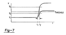
- Figure 7 shows a graph with voltage V on the vertical axis and time t on the horizontal axis.
- the capacitor 82 is discharged by making pin 4 an output low as discussed above.
- the voltage at pin 4 is V 1 after the capacitor 82 is discharged and the circuit 86 is at a steady state.
- pin 4 is switched to an analog A/D input and the voltage at pin 4 begins to rise.
- time t 2 here 1 ms after time t 1 , the voltage is measured at pin 4 by the converter 90.
- the voltage at pin 4 should be V 2 at time t 2 , which is above the threshold. If the capacitor 82 does exist in the battery pack 62, the voltage at pin 4 should be V 3 at time t 2 , which is below the threshold V T as shown by graph line 94.
Landscapes
- Engineering & Computer Science (AREA)
- Manufacturing & Machinery (AREA)
- Chemical & Material Sciences (AREA)
- Chemical Kinetics & Catalysis (AREA)
- Electrochemistry (AREA)
- General Chemical & Material Sciences (AREA)
- Power Engineering (AREA)
- Physics & Mathematics (AREA)
- General Physics & Mathematics (AREA)
- Secondary Cells (AREA)
- Charge And Discharge Circuits For Batteries Or The Like (AREA)
- Tests Of Electric Status Of Batteries (AREA)
Abstract
Description
- This invention relates generally to a battery charger monitor that monitors battery pack parameters during charging of a battery and, more particularly, to a battery charger monitor that monitors battery voltage, battery temperature and determines battery pack identification using an identification capacitor within the battery pack, where the battery pack identification and the battery temperature are monitored on a single line between the battery monitor and the battery pack.
- Many different electrical devices, such as some power tools, cellular phones, appliances, etc., use battery packs that are rechargeable. Modern battery chargers are capable of charging battery packs having different rated voltages and different battery chemistry, i.e., nickel-cadmium, metal hydride, lithium, etc. Most of these battery chargers monitor the voltage of the battery pack during the charging process to provide a full charge without exceeding the maximum charge of the battery pack which could cause damage to the pack. U.S. Patent Nos. 4,388,582 and 4,392,101, both issued to Sar et al., and assigned to the assignee of the present invention, disclose a quick battery charging technique which monitors the charging of a battery pack by noting inflection points in a voltage charging curve as the electrical chemical potential within the battery cells changes with respect to time. By determining specific inflection points in the charging curve, it is possible to accurately terminate the charging when the battery pack is at full charge.
- In addition to monitoring the voltage of a battery pack that is being charged, the battery monitor may also determine other pieces of useful information, including battery pack temperature and battery pack identification. Monitoring battery pack temperature is useful because overheating the battery pack during charging can cause significant damage to the battery pack. Determining the battery pack identification is desirable to ascertain certain things such as maximum battery voltage and capacity, battery chemistry, manufacturing date, etc. This information can be used by a charging control algorithm controlling the charging process to aid in monitoring and adjusting the charging process.
- Battery chargers and charger monitors that monitor battery voltage and battery temperature during the charging process can be found in U.S. Patent No. 5,352,969 and U.S. Patent Application Serial No. 08/834,375, filed April 16, 1997, titled "Indirect Thermal Sensing System for a Battery Charger", both assigned to the assignee of the instant application. Both of these documents disclose an analog-to-digital conversion technique that coverts an analog battery voltage signal to a digital representation suitable for microprocessor analysis. The battery voltage signal is attenuated by a voltage attenuation or prescaler circuit, acting as a voltage divider, to cause the battery voltage to be in a predetermined narrow range regardless of the battery voltage. The prescaler circuit allows the battery charger to effectively monitor the battery voltage for a wide range of battery packs having varying voltages. U.S. Patent Application Serial No. 08/834,375 also discloses a technique for monitoring battery temperature using a similar analog-to-digital conversion method.
- U.S. Patent No. 5,489,834 issued to Pitkanen discloses a battery type and temperature identification circuit. The battery pack being charged includes a negative temperature coefficient resistor, a voltage divider resistor, and a fixed identification resistor electrically connected in a voltage divider circuit. The identification resistor is different for each different battery pack type, and provides the basis for determining battery type. An output voltage from the voltage divider circuit follows a particular curve set by the identification resistor as the temperature on the pack changes. Because the value of the identification resistor is selected based on the battery pack type, and the values of the negative temperature coefficient resistor and voltage divider resistor are selected to be the same or nearly the same for each battery type, the different voltage curves at the output of the voltage divider circuit for the different battery types can be spaced apart. By determining which curve the output voltage follows for changes in temperature gives an indication of the battery pack identification.
- This technique does, however, suffer from a number of drawbacks and disadvantages. Particularly, because each of the voltage signals for the different battery packs are voltage divided by a particular identification resistor to be separated, the resolution of the voltage signal is low, and distinction between one voltage curve to a next voltage curve could provide error because of curve overlap. Because one voltage curve for one battery pack type is adjacent to another battery pack type, it may be impossible to tell whether the voltage representation is at the end of one voltage curve or at the beginning of a next voltage curve. Additionally, because the battery type identification circuit must have accurate resolution within the range of each voltage curve as well as over the entire range of the voltage curves combined, a very expensive analog-to-digital converter is required.
- German Patent Application No. DE 42 25 686 A1, published March 3, 1994 discloses a circuit for recognizing and charging a battery pack, where the battery pack includes a temperature dependent resistor and an identification capacitor. A microprocessor applies a DC voltage signal to the battery pack to determine the resistive value of the temperature dependent resistor. Next, a square wave signal is applied to the battery pack, and the impedance is measured. The value of the identification capacitor is then determined by the equation Z=1/(sqr(1/R)2 + (1/Xc)2) to identify the battery pack.
- What is needed is a battery charger monitor circuit that is able to charge a battery pack in the charger, monitor the voltage of the battery, monitor the temperature of the battery, and provide an indication of the battery pack identification in and efficient and cost effective manner, and doesn't suffer the drawbacks of the prior art devices discussed above. It is therefore, an object of the present invention to provide such a battery monitor circuit.
- In accordance with the present invention, there is provided a method of determining the identity of a battery pack, said method comprising the steps of:
- initiating charging of a capacitive component of a battery pack circuit of the battery pack;
- waiting a predetermined period of time after initiating the charging of the capacitive component; and
- measuring a voltage output of the battery pack circuit after the predetermined period of time to determine whether the voltage output is above or below a predetermined threshold value, characterised in that the method further comprises the step of discharging the capacitive component of the battery pack circuit prior to the step of initiating charging of the capacitive component.
- In accordance with the teachings of the present invention, a battery monitor is disclosed that uses a thermistor in combination with an AC circuit component (i.e. one that exhibits a recactance), such as a capacitor or an inductor, to determine battery pack temperature and battery pack identification. To determine the battery pack temperature, the resistance of the thermistor is measured when the battery pack circuit is in a steady-state condition. Next, an AC signal is applied to the battery pack circuit under a cynamic circuit condition to identify the AC circuit component and identify the battery pack. Thus, the temperature of the battery pack and the identification of the battery pack can be determined on a single line.
- According to one embodiment, to determine the battery pack temperature in one embodiment, a first voltage divider network is provided, including a reference capacitor, where an output voltage of the first voltage divider network is applied to one terminal of a comparator. A second voltage divider network is provided that is electrically connected to the battery pack. The second voltage divider network includes a thermistor positioned within the battery pack at a location suitable to take battery pack temperature measurements, and a plurality of resistors within the battery monitor circuit. The output of the second voltage divider network is applied to another terminal of the comparator. Once the reference capacitor is charged, it is allowed to discharge through the first voltage divider network. When the reference capacitor decays below the value of the output of the second voltage divider network, the comparator switches high. Because the values of the reference capacitor and the resistors in the first voltage divider network, and the plurality of resistors in the second voltage divider network are known, the resistive value of the thermistor can be determined based on the output of the comparator. This resistive value is representative of the temperature within the battery pack.
- According to one embodiment, the second voltage divider network and the comparator are also used to determine battery pack identification. An unknown identification capacitor that has a value unique to a particular battery pack is included in the battery pack, and is connected in circuit with the thermistor and the second voltage divider network. The battery monitor circuit can determine the capacitance value of the identification capacitor based on its discharge rate. One terminal of the comparator is switched to a low reference voltage potential once the identification capacitor has been charged and is at a steady state. The second voltage divider network includes a low value resistor that allows the identification capacitor to be quickly discharged. Once the voltage potential of the second divider network applied to the positive terminal of the comparator falls below the reference potential, the monitor can determine the value of the capacitor based on the known value of the resistances.
- In another embodiment, the identification of the battery pack is determined by whether a thermistor and a capacitor exist in the battery pack circuit. To determine whether the thermistor is in the battery pack circuit, a voltage output of a voltage divider network is measured. If the measurement indicates that the thermistor does exist, then the voltage measurement is used to determine the resistance of the thermistor. To determine whether the capacitor exists in the battery pack circuit, the capacitor is first discharged, assuming that it does exist. Next, charging of the capacitor is initiated, and after a predetermined period of time, a voltage output of the battery pack circuit is measured to determine whether it is above or below a predetermined threshold value. If it is above the threshold value, then the capacitor does not exist, and if it is below the threshold the capacitor does exist.
- Other advantages and objects of the present invention will become apparent to those skilled in the art from the subsequent detailed description, appended claims and drawings.
- Figure 1 is a circuit diagram of a battery pack monitoring circuit that determines battery pack voltage temperature and identity according to an embodiment of the present invention;
- Figure 2 is a graph of a voltage divider output of the circuit shown in Figure 1 having temperature on the horizontal axis and voltage on the vertical axis;
- Figure 3 is a graph of the log A/D timer counts as a function of temperature with voltage on the vertical axis and temperature on the horizontal axis;
- Figure 4 is a graph of the decay times of the identification capacitor with time on the vertical axis and temperature on the horizontal axis;
- Figure 5 is a graph of the decay time of the identification capacitor with time on the vertical axis and temperature on the horizontal axis;
- Figure 6 is a circuit diagram of a battery pack monitoring circuit that determines battery pack temperature and identity according to another embodiment of the present invention; and
- Figure 7 is a voltage output graph for determining the presence of a capacitor in the battery monitoring circuit of Figure 6, where voltage is on the vertical axis and time is on the horizontal axis.
- The following discussion of the preferred embodiments directed to a system for measuring battery temperature and determining battery pack identification in a battery charger is merely exemplary in nature, and is in no way intended to limit the invention or its applications or uses.
- Figure 1 shows a schematic diagram of a
battery monitoring circuit 10 that is separated into abattery pack side 12 and a battery charger side 14, according to an embodiment of the present invention. Thebattery pack side 12 is electrically connected to the battery charger side 14 at threeconnections battery monitor circuit 10 is used to monitor abattery pack 22 including a plurality ofbattery cells 24. Thebattery monitoring circuit 10 provides three major functions, including monitoring the charging process of thebattery pack 22, determining the temperature of thebattery pack 22, and identifying thebattery pack 22. Theconnection 16 connects a battery pack voltage measuring and charging line, theconnection 18 connects a battery pack temperature and battery pack identification line, and theconnection 20 provides a ground connection. Although not specifically shown, it will be understood that thebattery monitoring circuit 10 will include battery charging circuitry in association with the monitoring circuitry on the battery charger side 14. The battery pack identification can provide various desirable information, including battery chemistry, such as nickel cadmium, metal hydride, lithium, etc., number of cells 14, manufacturing date, rated voltage, etc. - The
battery monitoring circuit 10 is microprocessor controlled by amicroprocessor 26. Themicroprocessor 26 can be any suitable microprocessor for the purposes described herein, and as will be well understood by those in the art, many different microprocessors are available for this purpose. Four of the microprocessor pins are labeled 1, 2, 3 and 4 for purposes of the discussion herein. However, these pins will have different pin numbers depending on which microprocessor is used. As will be discussed in greater detail below, the battery pack temperature and the battery pack identification are both determined from a single connection atpin 2. - The
battery pack side 12 includes abattery pack circuit 30 in electrical connection with thebattery pack 22. Thebattery pack circuit 30 includes anidentification capacitor 32 and athermistor 34. Thethermistor 34 is a variable resistor that changes its resistance based on temperature, as is well understood in the art. Other types of temperature sensing devices may be applicable within the scope of the present invention, as would be appreciated by those skilled in the art. Theidentification capacitor 32 is specially selected to identify thebattery pack 22, and thus has a different capacitive value depending upon thepack 22. Thethermistor 34 is strategically placed within thebattery pack 22 so as to provide a temperature reading of thepack 22. Thus, everything on thebattery pack side 12 is removable from the actual battery charger as a single unit, and can be replaced with other battery packs. - In accordance with the teachings of the present invention, both the temperature of the
battery pack 22 and the identification of thebattery pack 22 are determined through a single connection to the battery charger side 14, hereconnection 18. The temperature of thebattery pack 22 is measured when thebattery pack circuit 30 is in a steady-state condition, where a DC signal is applied through theconnection 18. To determine the identification of thebattery pack 22, thebattery pack circuit 30 is put under a dynamic circuit condition to determine the value of thecapacitor 32. In an alternate embodiment, thecapacitor 32 can be replaced with another AC circuit component, such as an inductor. - The battery charger side 14 of the
battery monitoring circuit 10 includes avoltage attenuator 36 or prescaler circuit (resistor divider network) that is used to attenuate the output voltage of thebattery pack 12 to be at or near a desirable voltage output. The attenuation of thevoltage attenuator 36 can be selectively set so that the desirable voltage output is nearly the same for all battery packs 22 regardless of its actual voltage. This attenuated voltage is applied to the positive terminal of acomparator 38 atpin 1 of themicroprocessor 26. The charging voltage applied to thebattery pack 22 is applied through theconnection 16 from a current source (not shown) to charge thebattery pack 22. - The battery charger side 14 of the
battery monitor circuit 10 further includes anRC circuit 40. TheRC circuit 40 includes areference capacitor 42 having a known value, and resistors R1 and R2 also having known values that make up a voltage divider network within thecircuit 40. The output voltage of theRC circuit 40 is applied to pin 4 of themicroprocessor 26. When themicroprocessor 26 switches aswitch 44 to a suitable reference potential, here a plus five volt potential, thecapacitor 42 is charged through the resistor R2. After thecapacitor 42 has been charged and is at steady state, theswitch 44 is switched to a high impedance state, and the voltage of thecapacitor 42 dissipates through the resistor R1 at a known dissipation rate based on the values of thecapacitor 42 and the resistors R1 and R2. This capacitor dissipation voltage is applied to the negative (inverting) terminal of thecomparator 38 through aswitch 46. At the same time that theswitch 44 is switched to a high impedance state, themicroprocessor 26 begins counting at a predetermined clock pulse rate by an internal timer. Once the voltage potential of thecapacitor 42 falls below the attenuated voltage of thebattery pack 12, the output Vout of thecomparator 38 goes high, and themicroprocessor 26 stores the number of counts. - By programming the
microprocessor 26 with the values of thecapacitor 42, the resistors R1 and R2, and the selected attenuation value of thevoltage attenuator 36, the discharge of thecapacitor 42 will be known, and thus the voltage of thebattery pack 22 can be converted to a digital signal. A more detailed discussion of analog-to-digital conversion of a voltage potential as just described can be found in Patent No. 5,352,969 and U.S. Patent Application No. 08/834,375, mentioned above. For the purposes of the present invention, monitoring of the battery voltage in this manner is not necessary, and can be done by various techniques. - Resistors R3, R4 and R5 and the
thermistor 34 make up avoltage divider network 48. To determine the temperature of thebattery pack 22, theswitch 44 is connected to the five volt reference potential to charge thecapacitor 42, and pins 2 and 3 are set to a high impedance input state, i.e., open, so that theidentification capacitor 32 on thebattery pack side 12 is charged through the resistor R3. In this configuration, thethermistor 34 and the resistor R4 are connected in parallel, and combine with the resistor R3 to form thevoltage divider network 48. The output of thevoltage divider network 48 atpin 2 is now a function of the temperature of thebattery pack 22. A graph of this voltage divider output is shown in Figure 2, where the voltage output atpin 2 is on the vertical axis and temperature is on the horizontal axis. As is apparent, as the temperature increases, the resistance of thethermistor 34 goes down and the voltage divider output atpin 2 decreases. - The analog voltage divider output at
pin 2 is applied to the positive (noninverting) terminal of acomparator 50. The voltage signal from theRC circuit 40 is applied to pin 4 of themicroprocessor 26, which in turn is applied to the negative (inverting) input terminal of thecomparator 50 through theswitch 46. After thecapacitor 42 is charged, and theswitch 44 is switched to a high impedance state, thecapacitor 42 begins to discharge, and themicroprocessor 26 begins to count clock pulses. When the capacitor dissipation voltage atpin 4 drops below the voltage divider output signal of thecircuit 48 atpin 2, thecomparator 50 switches high and themicroprocessor 26 stores the count pulse as a digital conversion. This count pulse is a digital representation of the temperature. A technique for measuring temperature of a battery pack, and converting it to a digital representation in this manner is discussed in U.S. Patent Application No. 08/834,375. Figure 3 is a graph showing the voltage divider output atpin 2 in Log AD counts on the vertical axis and temperature on the horizontal axis. As is apparent, as the temperature goes up, the resistance of the thermistor goes down, the voltage output goes down and the digital count decreases. - The
comparators switches microprocessor 26. This configuration is shown by way of a non-limiting example in that these components can be external to themicroprocessor 26, and the outputs of thecomparators microprocessor 26. Further, the comparison between the various signals discussed above, and switching of the switches can be performed in software by programming themicroprocessor 26. The depiction shown in Figure 1 is solely intended to give an understanding of the basic operation of themonitoring circuit 10 of the invention. - In accordance with the teachings of the present invention, the identification of the
battery pack 22 is also determined atpin 2 of themicroprocessor 26. To accomplish this,pin 2 is set to a high impedance input state andpin 3 is set to a high output state by switching aswitch 52 to a +5 volt potential. In this configuration, thethermistor 34 and the resistor R4 are in parallel, and the resistor R3 and R5 are in parallel in thevoltage divider circuit 48. Thecapacitor 32 is charged through thevoltage divider circuit 48 by the high output state potential applied to the resistor R3 and R5. A low reference voltage, here 0.2 volts, is applied to the negative terminal of thecomparator 50 through theswitch 46, and an internal timer of themicroprocessor 26 is initialized. - Once the voltage across the
capacitor 32 reaches steady state, thecapacitor 32 is discharged by settingpin 3 to a low output state by switching theswitch 52 to ground and the internal timer is started. The charging and discharging of thecapacitor 32 provides a changing or dynamic circuit electrical condition. Because the resistor R5 has a much lower value than thethermistor 34 and the resistors R3 and R4, thecapacitor 32 discharges quickly through the resistor R5. Thus, the changing resistance of thethermistor 34 as the temperature changes does not have a significant effect on the discharge rate of thecapacitor 32. In this example, the resistor R5 has a value that is two magnitudes lower than the resistors R3 and R4 to provide this quick discharge. However, this is by way of a non-limiting example in that other values may be applicable for different designs. - When the voltage at
pin 2 from the discharge of thecapacitor 32 falls below the 0.2 reference voltage, thecomparator 50 switches high, and the timed count is stored. This count value represents a voltage discharge time of thecapacitor 32. Because the values of R3, R4, R5 and thethermistor 34 are known, the value of thecapacitor 32 can be determined based on its discharge rate. Because different values for different capacitors will have different discharge times for the same resistor values, by inserting a known capacitor in association with thebattery pack 22, thebattery pack 22 can be identified. - The values of the resistors R3 and R4 and the
thermistor 34 are selected so that the voltage drop across thethermistor 34 falls within the common mode input voltage range of thecomparator 50 and within the predicted temperature range of interest. However, these values are not optimized for measuring the voltage decay across thecapacitor 32 due to a large temperature dependency. This is apparent by viewing the graph shown in Figure 4, depicting the decay times versus temperature for different values of thecapacitor 32 without the resistor R5. This shows that without the lower value resistor R5, the temperature change on thethermistor 34 has a great effect on the discharge time of a capacitor having different values. Without the resistor R5, the process would consume a large amount of software resources when modeled as a microcontroller program, although it would work. However, the decay time temperature dependency can be dramatically reduced by the addition of the resistor R5. By connecting the resistor R5 to pin 3, one terminal of the resistor R5 can be set high when the resistors R3 and R5 are in parallel, or set low when thethermistor 34 and resistors R4 and R5 are in parallel to dynamically alter the output of thevoltage divider circuit 48. When the resistor R5 is floating, thevoltage divider circuit 48 is optimized for temperature readings. By making the resistor R5 small in comparison to thethermistor 34, and by settingpin 3 high or low, thevoltage divider circuit 48 is optimized for measuring the discharge time of thecapacitor 32. Because the value of the resistor R5 is small, it "overrides" the effects of the other resistances in thevoltage divider circuit 48, including thethermistor 34. This fast charging and discharging through the resistor R5 results in a capacitor decay time temperature independence as shown in the graph of Figure 5. - Another embodiment for determining battery pack temperature and battery pack identity is also disclosed, according to the present invention, that is a simplified version of the embodiment described above. Certain battery monitoring applications may only require the identification of a limited number of battery packs than that proposed by the embodiment described above. Figure 6 shows a schematic diagram of a
battery monitoring circuit 60 that is separated into abattery pack side 62 and abattery charger side 64, according to another embodiment of the present invention. Thebattery pack side 62 is electrically connected to thebattery charger side 64 at threeseparate connections battery monitoring circuit 60 is used to monitor abattery pack 72 that includes a plurality ofbattery cells 74. Theconnection 66 connects a battery pack voltage measuring and charging line, theconnection 68 connects a battery pack temperature and battery pack identification line, and theconnection 70 provides a ground connection. - The
battery monitoring circuit 60 is microprocessor controlled by amicroprocessor 76. Themicroprocessor 76 can be any suitable microprocessor for the purposes described herein, such as the Zilog Z86C83, known to those skilled in the art. Five of the microprocessor pins are labeled 1, 2, 3, 4 and 5 for purposes of discussion herein. However, these pins will have different pin numbers depending on which microprocessor is used. - The
battery pack 72 is charged by a control signal applied to pin 1 to turn on acurrent source 78. The voltage of thebattery pack 72 is measured atpin 2 of themicroprocessor 76 using a 12-bit log A/D converter 80 in the same manner as described above. The details of the charging and charge monitoring of thebattery pack 72 can be any suitable technique known in the art consistent with thebattery monitoring circuit 60. - The
battery pack side 62 includes anidentification capacitor 82 and athermistor 84, just as with the embodiment described above. However, in this embodiment, themonitoring circuit 60 does not identify thebattery pack 72 by determining the actual capacitance of thecapacitor 82, but determines the identity of thebattery pack 70 by whether thecapacitor 82 exists, regardless of its value, and whether thethermistor 84 exists. For certain battery packs, such as nickel cadmium battery packs, the temperature of the pack may not need to be determined, or may be determined by indirect thermal sensing or other thermal sensing techniques, and thus thethermistor 84 is not needed. Since theidentification capacitor 82 only has the purpose of determining the identity of thebattery pack 72, thecapacitor 82 can also be eliminated. Therefore, for certain types of battery packs, both thethermistor 84 and thecapacitor 82 can be eliminated. Accordingly, a first type of battery pack can be identified by determining that it does not have a thermistor or a capacitor, a second type of battery pack can be identified by determining that it has a thermistor and no capacitor, and a third type of battery pack can be identified by determining that it has both a thermistor and a capacitor. - The
charger side 64 of themonitoring circuit 60 includes acircuit 86 that includes a pull-up resistor R6 connected to a five volt potential and resistors R7 and R8 electrically connected as shown, that combine with thethermistor 84 to define a voltage divider network. In accordance with the teachings of the present invention, to determine if thethermistor 84 exists, the resistor R8 is electrically removed from thecircuit 86 by setting an analog/digital I/O atpin 4 of themicroprocessor 76 to a high impedance. Then, thethermistor 84 and the resistor R6 divide the +5 volt potential. The divided voltage is measured atpin 3 of themicroprocessor 76, where the voltage is applied to an 8-bit analog/digital converter 88 that converts the voltage to a digital representation readable by themicroprocessor 76. An 8-bit A/D converter is used in this embodiment because it provides a good absolute accuracy, although it has less resolution than the A/D converters identified above. Because the value of R6 is known, if thethermistor 84 did not exist in thebattery pack side 62, then thethermistor 84 would not act to divide the voltage. Themicroprocessor 76 would determine this by the value stored in the A/D converter 88. Likewise, if thethermistor 84 does exist in thebattery pack side 62, a different value will be stored in the A/D converter 88. Therefore, themicroprocessor 76 can identify whether thethermistor 84 exists or not. - If the
thermistor 84 does exist, themonitoring circuit 60 will determine the temperature of thebattery pack 72 by the resistance of thethermistor 84. Because the resistance value of thethermistor 84 will change based on the temperature of thepack 72, values stored in the A/D converter 88 will change based on the resistance value of thethermistor 84, giving an indication of the pack temperature in the manner as described above. - If the monitoring circuit determines that the thermistor does not exist in the
battery pack side 62, then it is determined that thebattery pack 72 is a particular battery pack type, such as a nickel cadmium battery pack. If themonitoring circuit 60 determines that thethermistor 84 does exist in thebattery pack side 62, it will then determine if thethermistor 84 has a value that falls within a certain range. If the resistive value of thethermistor 84 is within the range, thecircuit 60 then determines whether thecapacitor 82 does or doesn't exist. First,pin 4 is set as an output low to discharge thecapacitor 82 throughpin 4, assuming that it does exist. In this configuration, thepin 4 is a digital output.Pin 3 of themicroprocessor 76 is then set to a high impedance input to remove that connection from thecircuit 86. After thecapacitor 82 has had time to discharge and thecircuit 86 is at steady state,pin 4 is set to an analog high impedance input. The five voltage potential applied to the resistor R6 begins to charge thecapacitor 82. A voltage reading is then taken atpin 4 by an 8-bit analog/digital converter 90 a predetermined period of time after thepin 4 is set to an input, to measure the voltage of thecircuit 86. The predetermined period of time is less than the time it takes thecapacitor 82 to fully charge and thecircuit 86 to reach steady state. If the measured voltage is above a predetermined threshold when the time period has elapsed after thepin 4 is set to an analog input, then themicroprocessor 76 knows that thecapacitor 82 does not exist in thebattery pack 62 because the voltage of thecircuit 86 increased too fast. If the voltage atpin 4 is below the predetermined threshold, then themicroprocessor 76 makes a determination that thecapacitor 82 does exist. - For a specific example, the
capacitor 82 is 10µf and the threshold value is 0.7V. Figure 7 shows a graph with voltage V on the vertical axis and time t on the horizontal axis. Thecapacitor 82 is discharged by makingpin 4 an output low as discussed above. The voltage atpin 4 is V1 after thecapacitor 82 is discharged and thecircuit 86 is at a steady state. At time t1,pin 4 is switched to an analog A/D input and the voltage atpin 4 begins to rise. At time t2, here 1 ms after time t1, the voltage is measured atpin 4 by theconverter 90. If thecapacitor 82 does not exist, as shown by graph line 92, then the voltage atpin 4 should be V2 at time t2, which is above the threshold. If thecapacitor 82 does exist in thebattery pack 62, the voltage atpin 4 should be V3 at time t2, which is below the threshold VT as shown by graph line 94. - The foregoing discussion discloses and describes merely exemplary embodiments of the present invention. One skilled in the art will readily recognize from such discussion, and from the accompanying drawings and claims, that various changes, modifications and variations can be made therein without departing from the spirit and scope of the invention as defined in the following claims.
Claims (10)
- A method of determining the identity of a battery pack (72), said method comprising the steps of:initiating charging of a capacitive component (82) of a battery pack circuit of the battery pack;waiting a predetermined period of time after initiating the charging of the capacitive component (82); andmeasuring a voltage output of the battery pack circuit after the predetermined period of time to determine whether the voltage output is above or below a predetermined threshold value, characterised in that the method further comprises the step of discharging the capacitive component (82) of the battery pack circuit prior to the step of initiating charging of the capacitive component (82).
- A method as claimed in claim 1, wherein the step of measuring a voltage output includes determining that the battery pack circuit does not include the capacitive component (82) if the value output is above the threshold value and determining that the battery pack circuit does include the capacitive component (82) if the voltage output is below the threshold value.
- A method as claimed in claim 1 or claim 2, wherein the step of measuring the voltage output includes using an analog-to-digital converter to measure the voltage output.
- A method as claimed in any one of claims 1 to 3, wherein the predetermined time period is 1 ms.
- A method as claimed in any one of claims 1 to 4, wherein the predetermined threshold value is 0.7 volts.
- A method as claimed in any one of claims 1 to 5, wherein the step of discharging the capacitive component (82) includes setting an analog/digital input/output of a microprocessor to a digital output low, and the step of initiating recharging of the capacitive component (82) includes setting the analog/digital input/output to an analog input, said step of measuring a voltage output of the battery pack circuit includes measuring the voltage output at the analog input.
- A method as claimed in any one of claims 1 to 6, further comprising the step of determining if the battery pack (72) includes a temperature dependent resistive element (84).
- A method as claimed in any one of claims 1 to 7, wherein the step of determining if the battery pack circuit includes a resistive element (84) includes the step of determining the voltage output of a voltage divider network (86), where the resistive element (84) is part of the voltage divider network (86).
- A method as claimed in any one of claims 1 to 8, further comprising the step of determining the resistance of the resistive element (84) if it is determined that the resistive element (84) exists based on the voltage output of the voltage divider network (86).
- A method as claimed in claim 9, wherein the voltage output of the voltage divider network (86) is determined by an analog-to-digital converter.
Applications Claiming Priority (2)
| Application Number | Priority Date | Filing Date | Title |
|---|---|---|---|
| US09/094,302 US5945803A (en) | 1998-06-09 | 1998-06-09 | Apparatus for determining battery pack temperature and identity |
| EP99304483A EP0964258B1 (en) | 1998-06-09 | 1999-06-09 | Apparatus for determining battery pack temperature and identity |
Related Parent Applications (1)
| Application Number | Title | Priority Date | Filing Date |
|---|---|---|---|
| EP99304483A Division EP0964258B1 (en) | 1998-06-09 | 1999-06-09 | Apparatus for determining battery pack temperature and identity |
Publications (2)
| Publication Number | Publication Date |
|---|---|
| EP1637897A2 true EP1637897A2 (en) | 2006-03-22 |
| EP1637897A3 EP1637897A3 (en) | 2006-04-05 |
Family
ID=22244375
Family Applications (2)
| Application Number | Title | Priority Date | Filing Date |
|---|---|---|---|
| EP05022309A Withdrawn EP1637897A3 (en) | 1998-06-09 | 1999-06-09 | Method for determining the identity of a battery pack |
| EP99304483A Expired - Lifetime EP0964258B1 (en) | 1998-06-09 | 1999-06-09 | Apparatus for determining battery pack temperature and identity |
Family Applications After (1)
| Application Number | Title | Priority Date | Filing Date |
|---|---|---|---|
| EP99304483A Expired - Lifetime EP0964258B1 (en) | 1998-06-09 | 1999-06-09 | Apparatus for determining battery pack temperature and identity |
Country Status (7)
| Country | Link |
|---|---|
| US (1) | US5945803A (en) |
| EP (2) | EP1637897A3 (en) |
| JP (1) | JP2000032677A (en) |
| CN (1) | CN1140032C (en) |
| CA (1) | CA2273543C (en) |
| DE (1) | DE69933817T2 (en) |
| TW (1) | TW428336B (en) |
Cited By (3)
| Publication number | Priority date | Publication date | Assignee | Title |
|---|---|---|---|---|
| US7496460B2 (en) | 2006-09-06 | 2009-02-24 | Eastway Fair Company Limited | Energy source monitoring and control system for power tools |
| CN108032745A (en) * | 2017-11-24 | 2018-05-15 | 安徽特凯新能源科技有限公司 | A kind of battery management system suitable for low-temperature working |
| WO2021151773A1 (en) * | 2020-01-30 | 2021-08-05 | Robert Bosch Gmbh | Hand-held power tool and rechargeable battery pack for a hand-held power tool |
Families Citing this family (56)
| Publication number | Priority date | Publication date | Assignee | Title |
|---|---|---|---|---|
| JP3378189B2 (en) | 1998-02-28 | 2003-02-17 | 株式会社マキタ | Charging device and charging method |
| US6181102B1 (en) * | 1998-11-13 | 2001-01-30 | Agilent Technologies, Inc. | Battery pack chemistry detection and identification system and method |
| US6326767B1 (en) | 1999-03-30 | 2001-12-04 | Shoot The Moon Products Ii, Llc | Rechargeable battery pack charging system with redundant safety systems |
| US6215274B1 (en) * | 1999-10-27 | 2001-04-10 | Denso Corporation | Enhanced battery pack monitoring interface |
| US6246210B1 (en) * | 2000-01-27 | 2001-06-12 | Behavior Tech Computer Corp. | System for identifying electric devices |
| US6732449B2 (en) | 2000-09-15 | 2004-05-11 | Walter Evanyk | Dryer/blower appliance with efficient waste heat dissipation |
| US6891130B2 (en) * | 2000-09-15 | 2005-05-10 | Walter Evanyk | Appliance for dispensing melt adhesive with variable duty cycle and method of implementing |
| US6946623B2 (en) * | 2000-09-15 | 2005-09-20 | Powerpulse Technologies, L.P. | Appliance for liquefying solder with variable duty cycle and method of implementing |
| US7589500B2 (en) | 2002-11-22 | 2009-09-15 | Milwaukee Electric Tool Corporation | Method and system for battery protection |
| US7176654B2 (en) | 2002-11-22 | 2007-02-13 | Milwaukee Electric Tool Corporation | Method and system of charging multi-cell lithium-based batteries |
| US7425816B2 (en) * | 2002-11-22 | 2008-09-16 | Milwaukee Electric Tool Corporation | Method and system for pulse charging of a lithium-based battery |
| US7157882B2 (en) * | 2002-11-22 | 2007-01-02 | Milwaukee Electric Tool Corporation | Method and system for battery protection employing a selectively-actuated switch |
| US8471532B2 (en) | 2002-11-22 | 2013-06-25 | Milwaukee Electric Tool Corporation | Battery pack |
| JP4297836B2 (en) * | 2003-09-10 | 2009-07-15 | 三洋電機株式会社 | Consumable parts and identification device thereof |
| JP4819037B2 (en) * | 2004-05-04 | 2011-11-16 | オーツー マイクロ, インコーポレーテッド | Cordless power tool with tool identification circuit |
| EP1805863B1 (en) * | 2004-10-18 | 2013-06-26 | Black & Decker, Inc. | Cordless power system |
| CN1782953A (en) * | 2004-11-24 | 2006-06-07 | 鸿富锦精密工业(深圳)有限公司 | Identifying device for battery group Factory and its shape |
| KR100624942B1 (en) | 2004-11-29 | 2006-09-18 | 삼성에스디아이 주식회사 | Battery pack |
| CN2762964Y (en) | 2005-01-10 | 2006-03-08 | 南京德朔实业有限公司 | Electric tool power supplied by battery |
| US20070285055A1 (en) * | 2006-06-07 | 2007-12-13 | Meyer Gary D | Battery pack |
| US7508225B2 (en) * | 2006-09-07 | 2009-03-24 | Kyocera Wireless Corporation | Apparatus, system and method for identification with temperature dependent resistive device |
| US8188706B2 (en) * | 2007-02-16 | 2012-05-29 | Broadcom Corporation | Power management unit with battery detection controller and switchable regulator block |
| US20080305387A1 (en) * | 2007-06-11 | 2008-12-11 | Black & Decker Inc. | Cordless power tool system |
| EP2158523B1 (en) * | 2007-06-15 | 2019-07-31 | Black & Decker, Inc. | Multiplexing functionalities in a single channel of a microcontroller |
| US7433794B1 (en) * | 2007-07-18 | 2008-10-07 | Tesla Motors, Inc. | Mitigation of propagation of thermal runaway in a multi-cell battery pack |
| USD588985S1 (en) | 2007-10-17 | 2009-03-24 | Black & Decker Inc. | Battery charger |
| TWI354803B (en) * | 2007-12-31 | 2011-12-21 | High Tech Comp Corp | Battery module and method for determining a chargi |
| US8302600B2 (en) | 2008-09-30 | 2012-11-06 | Nellcor Puritan Bennett Llc | Battery management for a breathing assistance system |
| BRPI1010083A2 (en) * | 2009-06-22 | 2016-03-15 | Koninkl Philips Electronics Nv | power unit for supplying an electrically operated device with electrical power and / or electrical signal through connector elements for releasable contact of electrically operated device dedicated connector means, electrically operated device to cooperate with the power unit, electrical system and method for supply an electrically operated device with electrical power and / or electrical signal via connecting elements for a releasable contact of dedicated connectors of the electrically operated device |
| DE102009036608A1 (en) * | 2009-08-07 | 2011-02-24 | Sanyo Component Europe Gmbh | Rechargeable battery for use in e.g. mobile electrical device in electrical system, has digital signal unit connected with communication connections to send and receive information in form digital signal by connections |
| KR101093928B1 (en) * | 2009-11-26 | 2011-12-13 | 삼성에스디아이 주식회사 | Battery packs and methods for preventing high temperature swelling of battery cells |
| JP5476177B2 (en) * | 2010-03-26 | 2014-04-23 | パナソニック株式会社 | Electric tool |
| US9722334B2 (en) | 2010-04-07 | 2017-08-01 | Black & Decker Inc. | Power tool with light unit |
| CN102403742A (en) * | 2010-09-10 | 2012-04-04 | 亚帝森能源科技(深圳)有限公司 | Self-adaption multifunctional charging circuit and achieving method thereof |
| CN102183315A (en) * | 2011-02-28 | 2011-09-14 | 惠州Tcl移动通信有限公司 | Circuit and method for detecting identity (ID) and temperature of battery by using common detection pin |
| EP2734340B1 (en) * | 2011-07-24 | 2017-12-20 | Makita Corporation | Theft-deterrence system for power tool system, and adapter and method therefor |
| US9018906B2 (en) * | 2011-09-09 | 2015-04-28 | Samsung Sdi Co., Ltd. | Battery pack |
| US8915331B2 (en) * | 2011-09-29 | 2014-12-23 | Lincoln Industrial Corporation | Battery powered, handheld lubrication gun with display |
| DE102012204538A1 (en) * | 2012-03-21 | 2013-09-26 | Robert Bosch Gmbh | Storage for electrical energy and recording device for at least one memory for an electrically driven vehicle |
| CN103542955B (en) * | 2012-07-17 | 2016-08-03 | 昆山雅森电子材料科技有限公司 | Lithium ion battery temperature inductor |
| CN103675689A (en) * | 2012-09-24 | 2014-03-26 | 联想(北京)有限公司 | Battery detection method and device |
| CN103197258B (en) * | 2013-04-09 | 2015-12-02 | 青岛海信移动通信技术股份有限公司 | A battery type detection method and mobile terminal |
| CN103217650B (en) * | 2013-04-09 | 2015-10-21 | 青岛海信移动通信技术股份有限公司 | Battery type detection method and the mobile terminal adopting the method to design |
| CN104733790A (en) * | 2013-12-21 | 2015-06-24 | 苏州宝时得电动工具有限公司 | Multi-battery-pack common discharge protection parameter setting method and overload protection method |
| JP6211493B2 (en) * | 2014-09-10 | 2017-10-11 | 矢崎総業株式会社 | Temperature detection device |
| US10050461B2 (en) * | 2015-02-11 | 2018-08-14 | Mediatek Inc. | Charge control circuit, charge control method and associated power management integrated circuit |
| US9954259B1 (en) | 2016-12-07 | 2018-04-24 | Proterra Inc. | Thermal event management system for an electric vehicle |
| KR102076889B1 (en) * | 2017-02-15 | 2020-02-12 | 주식회사 엘지화학 | Unique number assignment system and method for cell module controller |
| CN108649662A (en) * | 2018-06-27 | 2018-10-12 | 大唐终端技术有限公司 | A kind of SCM Based charging circuit and charging method |
| JP7259614B2 (en) * | 2019-07-19 | 2023-04-18 | 株式会社デンソー | battery monitor |
| EP3940916A1 (en) | 2020-07-14 | 2022-01-19 | Illinois Tool Works, Inc. | Battery pack and battery charger with battery type identifying device |
| US12170450B2 (en) * | 2020-11-20 | 2024-12-17 | Milwaukee Electric Tool Corporation | Systems and methods for identifying a battery pack for a battery pack powered power tool |
| US11808257B2 (en) | 2021-04-15 | 2023-11-07 | Black & Decker Inc. | Cordless compressor |
| CN116707091B (en) * | 2023-06-26 | 2024-08-09 | 北京领创医谷科技发展有限责任公司 | An intelligent charging cabin with identification function |
| KR20250107041A (en) * | 2024-01-04 | 2025-07-11 | 삼성에스디아이 주식회사 | Method and apparatus for setting battery pack identifier |
| EP4592032A1 (en) * | 2024-01-23 | 2025-07-30 | Techtronic Cordless GP | Power tool |
Family Cites Families (17)
| Publication number | Priority date | Publication date | Assignee | Title |
|---|---|---|---|---|
| US4006396A (en) * | 1974-01-18 | 1977-02-01 | Motorola, Inc. | Universal battery charging apparatus |
| US3911351A (en) * | 1974-04-08 | 1975-10-07 | Espey Mfg & Electronics Corp | Battery charging protective circuit for use in charging nickel cadmium batteries |
| US5144217A (en) * | 1989-03-03 | 1992-09-01 | Black & Decker Inc. | Cordless tool battery housing and charging system |
| DE3815001A1 (en) * | 1988-05-03 | 1989-11-16 | Ullmann Ulo Werk | DEVICE FOR CHARGING ACCUMULATORS |
| US5352969A (en) * | 1991-05-30 | 1994-10-04 | Black & Decker Inc. | Battery charging system having logarithmic analog-to-digital converter with automatic scaling of analog signal |
| US5184059A (en) * | 1991-09-16 | 1993-02-02 | Motorola, Inc. | Expanded battery capacity identification scheme and apparatus |
| US5120169A (en) * | 1991-10-09 | 1992-06-09 | Emhart Inc. | Blind fastener |
| JPH05251113A (en) * | 1992-03-06 | 1993-09-28 | Matsushita Electric Ind Co Ltd | Battery pack and charging apparatus |
| FI90929C (en) * | 1992-05-25 | 1994-04-11 | Nokia Mobile Phones Ltd | Coupling for detecting the temperature and type of a battery |
| US5411816A (en) * | 1992-07-02 | 1995-05-02 | Motorola, Inc. | Method and apparatus for determining battery characteristics |
| DE4225686A1 (en) * | 1992-08-04 | 1994-03-03 | Rawe Electronik Gmbh | Microprocessor circuit arrangement for identifying and charging a battery pack - detects and displays electrical code, and processes signal from temp. sensor in battery pack |
| US5325040A (en) * | 1992-09-21 | 1994-06-28 | Motorola, Inc. | Method and apparatus for charging a battery powered electronic device |
| GB2270983B (en) * | 1992-09-29 | 1996-04-10 | Nokia Mobile Phones Ltd | Battery identification |
| JP3296624B2 (en) * | 1993-05-26 | 2002-07-02 | 三洋電機株式会社 | Electrical equipment that determines the type of battery pack |
| US5548201A (en) * | 1994-09-13 | 1996-08-20 | Norand Corporation | Battery charging method and apparatus with thermal mass equalization |
| US5874825A (en) * | 1996-05-03 | 1999-02-23 | Black & Decker Inc. | Indirect thermal sensing system for a battery charger |
| DE19817423C2 (en) * | 1998-04-18 | 2003-09-18 | Metabowerke Gmbh | Method and device for recognizing a battery pack |
-
1998
- 1998-06-09 US US09/094,302 patent/US5945803A/en not_active Expired - Lifetime
-
1999
- 1999-06-03 CA CA002273543A patent/CA2273543C/en not_active Expired - Fee Related
- 1999-06-09 DE DE69933817T patent/DE69933817T2/en not_active Expired - Lifetime
- 1999-06-09 JP JP11162429A patent/JP2000032677A/en active Pending
- 1999-06-09 EP EP05022309A patent/EP1637897A3/en not_active Withdrawn
- 1999-06-09 CN CNB991095138A patent/CN1140032C/en not_active Expired - Fee Related
- 1999-06-09 EP EP99304483A patent/EP0964258B1/en not_active Expired - Lifetime
- 1999-07-07 TW TW088109528A patent/TW428336B/en not_active IP Right Cessation
Cited By (7)
| Publication number | Priority date | Publication date | Assignee | Title |
|---|---|---|---|---|
| US7496460B2 (en) | 2006-09-06 | 2009-02-24 | Eastway Fair Company Limited | Energy source monitoring and control system for power tools |
| US7580803B2 (en) | 2006-09-06 | 2009-08-25 | Techtronic Power Tools Technology Limited | Energy source monitoring and control system |
| CN108032745A (en) * | 2017-11-24 | 2018-05-15 | 安徽特凯新能源科技有限公司 | A kind of battery management system suitable for low-temperature working |
| CN108032745B (en) * | 2017-11-24 | 2021-06-01 | 安徽特凯新能源科技有限公司 | Battery management system suitable for low temperature work |
| WO2021151773A1 (en) * | 2020-01-30 | 2021-08-05 | Robert Bosch Gmbh | Hand-held power tool and rechargeable battery pack for a hand-held power tool |
| US20230047547A1 (en) * | 2020-01-30 | 2023-02-16 | Robert Bosch Gmbh | Hand-Held Power Tool and Rechargeable Battery Pack for a Hand-Held Power Tool |
| US12562406B2 (en) * | 2020-01-30 | 2026-02-24 | Robert Bosch Gmbh | Hand-held power tool and rechargeable battery pack for a hand-held power tool |
Also Published As
| Publication number | Publication date |
|---|---|
| EP1637897A3 (en) | 2006-04-05 |
| CA2273543C (en) | 2008-11-18 |
| CN1140032C (en) | 2004-02-25 |
| EP0964258B1 (en) | 2006-11-02 |
| DE69933817D1 (en) | 2006-12-14 |
| EP0964258A3 (en) | 2000-08-02 |
| EP0964258A2 (en) | 1999-12-15 |
| CN1238462A (en) | 1999-12-15 |
| JP2000032677A (en) | 2000-01-28 |
| DE69933817T2 (en) | 2007-08-30 |
| US5945803A (en) | 1999-08-31 |
| TW428336B (en) | 2001-04-01 |
| CA2273543A1 (en) | 1999-12-09 |
Similar Documents
| Publication | Publication Date | Title |
|---|---|---|
| US5945803A (en) | Apparatus for determining battery pack temperature and identity | |
| CA1260058A (en) | Controller for battery charger | |
| US8203305B1 (en) | Enhanced voltage-based fuel gauges and methods | |
| KR100616163B1 (en) | Battery Cell Monitoring And Balancing Circuit | |
| US6020721A (en) | Indirect thermal sensing system for a battery charger | |
| US8981782B2 (en) | Method and apparatus for monitoring the maximum available capacity of a battery | |
| WO1999023738A1 (en) | Method and apparatus for charging a battery | |
| JP2007513594A (en) | Method for balance charging a lithium ion or lithium polymer battery | |
| WO2004095611A1 (en) | Combination battery and battery pack using combination battery | |
| US5798933A (en) | High precision relative digital voltage measurement | |
| US6781348B2 (en) | Method of charging a storage battery | |
| JP2001204141A (en) | Detector for cell voltage of set battery and detecting method therefor | |
| JP2004271342A (en) | Charge / discharge control system | |
| EP1478932B1 (en) | Method and circuit arrangement for determining the average current consumption of a battery-operated apparatus | |
| US6094051A (en) | Apparatus and method for detecting memory effect in nickel cadmium batteries | |
| EP1114329A1 (en) | Apparatus and method for determining the capacity of a nickel-cadmium battery | |
| CN119179009A (en) | Battery real-time internal short circuit detection | |
| JPH08149709A (en) | Rechargeable battery charger | |
| JPH10322917A (en) | Method and apparatus for determining deterioration of secondary battery | |
| JPH07110109B2 (en) | Charger |
Legal Events
| Date | Code | Title | Description |
|---|---|---|---|
| PUAI | Public reference made under article 153(3) epc to a published international application that has entered the european phase |
Free format text: ORIGINAL CODE: 0009012 |
|
| PUAL | Search report despatched |
Free format text: ORIGINAL CODE: 0009013 |
|
| 17P | Request for examination filed |
Effective date: 20051013 |
|
| AC | Divisional application: reference to earlier application |
Ref document number: 0964258 Country of ref document: EP Kind code of ref document: P |
|
| AK | Designated contracting states |
Kind code of ref document: A2 Designated state(s): DE FR GB IT |
|
| AX | Request for extension of the european patent |
Extension state: AL LT LV MK RO SI |
|
| AK | Designated contracting states |
Kind code of ref document: A3 Designated state(s): DE FR GB IT |
|
| AX | Request for extension of the european patent |
Extension state: AL LT LV MK RO SI |
|
| AKX | Designation fees paid |
Designated state(s): DE FR GB |
|
| STAA | Information on the status of an ep patent application or granted ep patent |
Free format text: STATUS: THE APPLICATION IS DEEMED TO BE WITHDRAWN |
|
| 18D | Application deemed to be withdrawn |
Effective date: 20060930 |