EP1637821A2 - Air conditioner control logic for compressor noise and torque management - Google Patents
Air conditioner control logic for compressor noise and torque management Download PDFInfo
- Publication number
- EP1637821A2 EP1637821A2 EP05020459A EP05020459A EP1637821A2 EP 1637821 A2 EP1637821 A2 EP 1637821A2 EP 05020459 A EP05020459 A EP 05020459A EP 05020459 A EP05020459 A EP 05020459A EP 1637821 A2 EP1637821 A2 EP 1637821A2
- Authority
- EP
- European Patent Office
- Prior art keywords
- compressor
- time
- air conditioner
- computer controller
- refrigerant
- Prior art date
- Legal status (The legal status is an assumption and is not a legal conclusion. Google has not performed a legal analysis and makes no representation as to the accuracy of the status listed.)
- Granted
Links
Images


Classifications
-
- B—PERFORMING OPERATIONS; TRANSPORTING
- B60—VEHICLES IN GENERAL
- B60H—ARRANGEMENTS OF HEATING, COOLING, VENTILATING OR OTHER AIR-TREATING DEVICES SPECIALLY ADAPTED FOR PASSENGER OR GOODS SPACES OF VEHICLES
- B60H1/00—Heating, cooling or ventilating devices
- B60H1/32—Cooling devices
- B60H1/3204—Cooling devices using compression
- B60H1/3205—Control means therefor
- B60H1/3216—Control means therefor for improving a change in operation duty of a compressor in a vehicle
-
- F—MECHANICAL ENGINEERING; LIGHTING; HEATING; WEAPONS; BLASTING
- F25—REFRIGERATION OR COOLING; COMBINED HEATING AND REFRIGERATION SYSTEMS; HEAT PUMP SYSTEMS; MANUFACTURE OR STORAGE OF ICE; LIQUEFACTION SOLIDIFICATION OF GASES
- F25B—REFRIGERATION MACHINES, PLANTS OR SYSTEMS; COMBINED HEATING AND REFRIGERATION SYSTEMS; HEAT PUMP SYSTEMS
- F25B49/00—Arrangement or mounting of control or safety devices
- F25B49/02—Arrangement or mounting of control or safety devices for compression type machines, plants or systems
- F25B49/022—Compressor control arrangements
-
- B—PERFORMING OPERATIONS; TRANSPORTING
- B60—VEHICLES IN GENERAL
- B60H—ARRANGEMENTS OF HEATING, COOLING, VENTILATING OR OTHER AIR-TREATING DEVICES SPECIALLY ADAPTED FOR PASSENGER OR GOODS SPACES OF VEHICLES
- B60H1/00—Heating, cooling or ventilating devices
- B60H1/00507—Details, e.g. mounting arrangements, desaeration devices
- B60H2001/006—Noise reduction
-
- B—PERFORMING OPERATIONS; TRANSPORTING
- B60—VEHICLES IN GENERAL
- B60H—ARRANGEMENTS OF HEATING, COOLING, VENTILATING OR OTHER AIR-TREATING DEVICES SPECIALLY ADAPTED FOR PASSENGER OR GOODS SPACES OF VEHICLES
- B60H1/00—Heating, cooling or ventilating devices
- B60H1/32—Cooling devices
- B60H2001/3236—Cooling devices information from a variable is obtained
- B60H2001/3248—Cooling devices information from a variable is obtained related to pressure
- B60H2001/3251—Cooling devices information from a variable is obtained related to pressure of the refrigerant at a condensing unit
-
- B—PERFORMING OPERATIONS; TRANSPORTING
- B60—VEHICLES IN GENERAL
- B60H—ARRANGEMENTS OF HEATING, COOLING, VENTILATING OR OTHER AIR-TREATING DEVICES SPECIALLY ADAPTED FOR PASSENGER OR GOODS SPACES OF VEHICLES
- B60H1/00—Heating, cooling or ventilating devices
- B60H1/32—Cooling devices
- B60H2001/3236—Cooling devices information from a variable is obtained
- B60H2001/3255—Cooling devices information from a variable is obtained related to temperature
- B60H2001/3263—Cooling devices information from a variable is obtained related to temperature of the refrigerant at an evaporating unit
-
- B—PERFORMING OPERATIONS; TRANSPORTING
- B60—VEHICLES IN GENERAL
- B60H—ARRANGEMENTS OF HEATING, COOLING, VENTILATING OR OTHER AIR-TREATING DEVICES SPECIALLY ADAPTED FOR PASSENGER OR GOODS SPACES OF VEHICLES
- B60H1/00—Heating, cooling or ventilating devices
- B60H1/32—Cooling devices
- B60H2001/3236—Cooling devices information from a variable is obtained
- B60H2001/3266—Cooling devices information from a variable is obtained related to the operation of the vehicle
-
- B—PERFORMING OPERATIONS; TRANSPORTING
- B60—VEHICLES IN GENERAL
- B60H—ARRANGEMENTS OF HEATING, COOLING, VENTILATING OR OTHER AIR-TREATING DEVICES SPECIALLY ADAPTED FOR PASSENGER OR GOODS SPACES OF VEHICLES
- B60H1/00—Heating, cooling or ventilating devices
- B60H1/32—Cooling devices
- B60H2001/3269—Cooling devices output of a control signal
- B60H2001/327—Cooling devices output of a control signal related to a compressing unit
-
- B—PERFORMING OPERATIONS; TRANSPORTING
- B60—VEHICLES IN GENERAL
- B60H—ARRANGEMENTS OF HEATING, COOLING, VENTILATING OR OTHER AIR-TREATING DEVICES SPECIALLY ADAPTED FOR PASSENGER OR GOODS SPACES OF VEHICLES
- B60H1/00—Heating, cooling or ventilating devices
- B60H1/32—Cooling devices
- B60H2001/3269—Cooling devices output of a control signal
- B60H2001/328—Cooling devices output of a control signal related to an evaporating unit
- B60H2001/3282—Cooling devices output of a control signal related to an evaporating unit to control the air flow
-
- F—MECHANICAL ENGINEERING; LIGHTING; HEATING; WEAPONS; BLASTING
- F25—REFRIGERATION OR COOLING; COMBINED HEATING AND REFRIGERATION SYSTEMS; HEAT PUMP SYSTEMS; MANUFACTURE OR STORAGE OF ICE; LIQUEFACTION SOLIDIFICATION OF GASES
- F25B—REFRIGERATION MACHINES, PLANTS OR SYSTEMS; COMBINED HEATING AND REFRIGERATION SYSTEMS; HEAT PUMP SYSTEMS
- F25B2500/00—Problems to be solved
- F25B2500/12—Sound
-
- F—MECHANICAL ENGINEERING; LIGHTING; HEATING; WEAPONS; BLASTING
- F25—REFRIGERATION OR COOLING; COMBINED HEATING AND REFRIGERATION SYSTEMS; HEAT PUMP SYSTEMS; MANUFACTURE OR STORAGE OF ICE; LIQUEFACTION SOLIDIFICATION OF GASES
- F25B—REFRIGERATION MACHINES, PLANTS OR SYSTEMS; COMBINED HEATING AND REFRIGERATION SYSTEMS; HEAT PUMP SYSTEMS
- F25B2500/00—Problems to be solved
- F25B2500/26—Problems to be solved characterised by the startup of the refrigeration cycle
-
- F—MECHANICAL ENGINEERING; LIGHTING; HEATING; WEAPONS; BLASTING
- F25—REFRIGERATION OR COOLING; COMBINED HEATING AND REFRIGERATION SYSTEMS; HEAT PUMP SYSTEMS; MANUFACTURE OR STORAGE OF ICE; LIQUEFACTION SOLIDIFICATION OF GASES
- F25B—REFRIGERATION MACHINES, PLANTS OR SYSTEMS; COMBINED HEATING AND REFRIGERATION SYSTEMS; HEAT PUMP SYSTEMS
- F25B2600/00—Control issues
- F25B2600/02—Compressor control
- F25B2600/025—Compressor control by controlling speed
- F25B2600/0251—Compressor control by controlling speed with on-off operation
Definitions
- the present invention generally relates to an air conditioner. More specifically, the present invention relates to an air conditioner control system for reducing refrigerant noise and for managing torque, during initial engagement of a compressor of the air conditioner.
- a typical automobile air conditioner includes a compressor, a condenser, an expansion valve or orifice tube, and an evaporator.
- the compressor compresses a cool vapor-phase refrigerant (e.g., Freon, R134a) to heat the same, resulting in a hot, high-pressure vapor-phase refrigerant.
- This hot vapor-phase refrigerant runs through a condenser, typically a coil that dissipates heat.
- the condenser condenses the hot vapor-phase refrigerant into liquid refrigerant.
- the liquid refrigerant is throttled through an expansion valve, which evaporates the refrigerant to a cold, low-pressure saturated liquid-vapor-phase refrigerant.
- This cold saturated liquid-vapor-phase refrigerant runs through the evaporator, typically a coil that absorbs heat from the air fed to the passenger compartment.
- the rapid pressure changes that occur with the compressor cycling from OFF to ON can create various sounds and vibrations that may be unpleasant to humans.
- the origin of these sounds and vibrations include, but not limited to, purging liquid from the compressor (known as slugging) and the refrigerant passing through the expansion valve or orifice tube.
- slugging purging liquid from the compressor
- this slugging of the refrigerant can increase the torque needed to start the compressor. This increase in the compressor torque requirement can have an adverse affect on the performance of the vehicle.
- the present invention relates to an air conditioner comprising a heat removal device, an evaporator, a compressor and a controller.
- refrigerant noises can be due to purging liquid from the compressor (e.g., slugging) and/or due to refrigerant passing through the expansion valve or orifice tube.
- These sounds may include, but are not limited to, a bang, a knock, a clunk, a clang, a hissing etc., and may also include multiple variations, combinations, and repetitions thereof.
- One object of the present invention is to provide an air conditioner with control logic that is quieter and/ or easier to operate at start up.
- the air conditioner of the present invention was basically contrived to avoid to the greatest extent possible the adverse effects of the compressor being started, e.g., minimizes the refrigerant noises at compressor start up and/or decrease the compressor torque requirements due to slugging at compressor start up.
- an air conditioner that basically comprises a heat removal device, an evaporator, a compressor and a controller.
- the heat removal device is configured to receive a refrigerant in a compressed state and remove heat from at least a portion of the refrigerant.
- the evaporator is in fluid communication with the heat removal device to receive the refrigerant, and is configured to evaporate at least a portion of the refrigerant.
- the compressor is in fluid communication with the evaporator, and configured to compress the refrigerant and deliver the refrigerant in the compressed state to the heat removal device.
- the controller is operatively coupled to the compressor to selectively operate the compressor in response to a compressor request signal.
- the controller is configured to cycle the compressor between at least one ON operating state for a period of time and at least one OFF operating state for a prescribed period of time and then operate the compressor for an additional period of time.
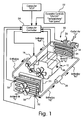
- Figure 1 is a simplified schematic diagram of a portion of vehicle equipped with a refrigerant circuit in accordance with a first embodiment of the present invention
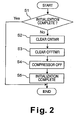
- Figure 2 is a first flowchart showing an initialization control logic or operations executed by the engine control unit or computer for a full time pulsing logic in accordance with the first embodiment of the present invention
- Figure 3 is a second flowchart showing a preferred full time pulsing control logic or operations executed by the computer in accordance with the first embodiment of the present invention
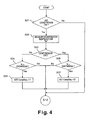
- Figure 4 is a third flowchart showing an exemplary normal control logic or operations executed by the computer in accordance with the first embodiment of the present invention
- Figure 5 is a fourth flowchart showing a modified pulsing control logic or operations executed by the computer as part of the pulsing control logic shown in Figure 3;
- Figure 6 is a fifth flowchart showing an initialization control logic or operations executed by the engine control unit or computer for a one time pulsing logic in accordance with a second embodiment of the present invention.
- Figure 7 is a sixth flowchart showing a one time pulsing control logic or operations executed by the computer in accordance with the second embodiment of the present invention.
- an air conditioner 10 is illustrated in accordance with a first embodiment of the present invention.
- the air conditioner 10 is particularly suitable for an automobile or other passenger vehicle (such as but not limited to a car, an SUV, a minivan, a station wagon, a pick-up truck, etc.,) as well as refrigeration systems for homes and industrial use.
- the air conditioner 10 is driven by a vehicle engine 12 in a conventional manner.
- the air conditioner 10 has a refrigerant circuit that includes an evaporator 14, a compressor 16 with an electromagnetic clutch, a condenser 18 and an expansion valve or orifice 20.
- the condenser 18 is located in front of a radiator 21 that cools the engine coolant of the engine 12.
- These components 14, 16, 18 and 20 are conventional components that are well known in the air conditioning field. Since these components 14, 16, 18 and 20 are well known in the air conditioning field, the structures of the components 14, 16, 18 and 20 will not be discussed or illustrated in detail herein.
- the compressor 16 is fluidly connected to the condenser 18 via a refrigerant pipe or conduit.
- the evaporator 14 is also fluidly connected to the compressor 16 via a refrigerant pipe or conduit.
- the expansion valve 20 is fluidly connected to the condenser 18 via a refrigerant pipe or conduit, and to the evaporator 14 by a refrigerant pipe or conduit.
- a refrigerant e.g., Freon, R134a
- a refrigerant e.g., Freon, R134a
- the compressor 16 receives and compresses a cool vapor-phase refrigerant from the evaporator 14.
- the compressor 16 is energizing or de-energizing the electromagnetic clutch of the compressor 16.
- the compression action heats the refrigerant, resulting in a hot, high-pressure vapor-phase refrigerant.
- This hot vapor-phase refrigerant is then fed through the condenser 18, such as an air-cooled coil that dissipates heat.
- the condenser 18 condenses the hot vapor-phase refrigerant into a liquid-phase refrigerant or a saturated liquid-vapor-phase refrigerant. In the preferred embodiment of the present invention, the condenser 18 condenses the refrigerant by air cooling.
- the condenser 18 of the preferred embodiment is a heat removal device.
- the condensed refrigerant is then delivered through the expansion valve 20, which expands the liquid-phase or saturated liquid-vapor-phase refrigerant to a cold, low-pressure liquid-vapor-phase refrigerant having a higher vapor content.
- the high pressure refrigerant passes through the expansion valve 20 so as to be throttled to a low pressure and temperature.
- the cold liquid-vapor-phase refrigerant (having a higher vapor content than the refrigerant exiting the condenser) runs through the evaporator 14, typically a coil that absorbs heat from and cools the air delivered to the passenger compartment or vehicle cabin.
- the operations of the air conditioner 10 are controlled by a set of operator controls 22 that are located in the cabin of the vehicle.
- the operator controls 22 typically will include an ON/OFF switch, a temperature control and a blower of fan speed control.
- a control signal is received by a computer controller 24 of the computer or engine control unit ECU.
- the computer controller 24 operates the air conditioner 10 in accordance with the settings of the operator controls 22.
- the computer controller 24 basically controls the operation of the air conditioner 10 by operating the compressor 16 between an ON operating state and an OFF operating state.
- the computer controller 24 selectively activates and deactivates a compressor clutch of the compressor 16 to switch between the ON operating state and the OFF operating state.
- the computer controller 24 selectively activates the compressor 16 between the ON and OFF operating states based on various control signals so as to substantially maintain the passenger compartment or vehicle cabin at a prescribed temperature setting that was set by the operator controls 22.
- the computer controller 24 selectively controls a fan or blower 26 at a prescribed fan speed in accordance with a fan speed setting that was set by the operator controls 22.
- the normal control logic of the air conditioner 10 is based on control signals from one or more of the following sensors: an outside air temperature sensor 30, a refrigerant pressure transducer or sensor 32, an evaporator temperature sensor 34, and an engine coolant temperature sensor 36.
- the outside air temperature sensor 30 is configured and arranged to detect the outside air temperature Ta, and output a signal to the computer controller 24 that is indicative of the outside air temperature Ta.
- the outside air temperature sensor 30 is disposed in front of the condenser 18.
- the refrigerant pressure transducer or sensor 32 is configured and arranged to detect the refrigerant pressure P inside the condenser 18, and output a signal to the computer controller 24 that is indicative of the refrigerant pressure P.
- the evaporator temperature sensor 34 is configured and arranged to detect the evaporator temperature Te, and output a signal to the computer controller 24 that is indicative of the evaporator temperature Te.
- the engine coolant temperature sensor 36 is configured and arranged to detect the temperature of the engine coolant Tw, and output a signal to the computer controller 24 that is indicative of the temperature of the engine coolant Tw.
- control of the air conditioner 10 during normal control operations is not important to the present invention.
- the normal control logic of the air conditioner 10 will only be briefly discussed below in a simplified manner with respect to the flow chart illustrated in Figure 4. Rather, the description of the present invention will focus on the control logic or operations during initial engagement of the compressor 16 of the air conditioner 10 for reducing refrigerant noise and for managing compressor torque.
- the control logic or operations during initial engagement of the compressor 16 of the air conditioner 10 is controlled by the computer controller 24.
- the computer controller 24 preferably includes a microprocessor and an air conditioner control program that controls the compressor 16 as discussed below.
- the computer controller 24 can also include other conventional components such as an input interface circuit, an output interface circuit, and storage devices such as a ROM (Read Only Memory) device and a RAM (Random Access Memory) device.
- the microprocessor of the computer controller 24 is programmed to control the air conditioner 10.
- the memory circuit stores processing results and control programs for controlling the operation of the compressor 16.
- the computer controller 24 is operatively coupled to the engine control unit ECU in a conventional manner.
- the internal RAM of the computer controller 24 stores statuses of operational flags and various control data.
- the internal ROM of the computer controller 24 stores the control logic for various operations of air conditioner 10.
- the computer controller 24 is configured and arranged to initially cycle the compressor 16 between at least one ON operating state for a predetermined period of time and at least one OFF operating state for a prescribed period of time, and then subsequently operate the compressor 16 using normal logic for an additional period of time, i.e., until the cabin temperature has reached the temperature setting that was set by the operator utilizing the operator controls 22.
- the computer controller 24 includes a compressor ON timer that is configured to at least measure the time that the compressor 16 is in the ON operating state and a compressor OFF timer that is configured to at least measure the time that the compressor 16 is in the OFF operating state.
- this cycling of the compressor 16 by the computer controller 24 occurs each and every time the compressor 16 is started.
- the computer controller 24 produces a compressor request signal to start the compressor 16 once the air conditioner 10 has been turned ON.
- a compressor request flag CompReq is set to "1" to represent that the compressor 16 has been set to an ON operating state.
- the compressor request flag CompReq is set to "0" to represent that the compressor 16 has been set to an OFF operating state.
- the computer controller 24 can be set to repeatedly cycle the compressor 16 between the ON operating state and the OFF operating state as needed and/or desired.
- This cycling of the compressor 16 between the ON and OFF operating states reduces the refrigerant noises occurring during start up of the compressor 16, as well as reduces the torque load on the engine 12 that may occur due to slugging of the compressor 16.
- This control logic of the present invention is preferably run in a timing loop such that other routines can be conducted without waiting.
- the compressor 16 is turned ON for approximately one second and then turned OFF for one second before the compressor 16 is continuously run until the evaporator 14 reaches the desired temperature needed for cooling the vehicle cabin in response to the temperature setting by the operator controls 22.
- the cycling times can be extended or shortened.
- the entire cycling of the compressor 16 between the ON and OFF operating states occurs within approximately three or four seconds.
- these prescribed time periods can be extended depending upon the applications.
- the prescribed period for the ON and OFF operating states can be varied based on the ambient temperature.
- the computer controller 24 can be configured to increase the length of the prescribed time period for the OFF operating state when the ambient temperature becomes lower, while maintaining the prescribed time period for the ON operating state constant or varying the length of the prescribed time period for the ON operating state as needed and/or desired for the particular situation.
- control operations executed by the computer controller 24 will now be described with reference to the functional block diagrams or flow charts of Figures 2 to 7. Many of the functions described below are functions that are preferably executed using software processing.
- the control routine of Figure 2 is only executed shortly after the engine 12 is started.
- the control routines of Figures 3 and 7, on the other hand, are periodically executed in a cyclic manner at a prescribed fixed time interval when the engine 12 is operating in accordance with certain predetermined operating conditions, e.g., when the air conditioner 10 has been turned ON.
- FIG. 2 a first flowchart is illustrated showing an initialization control logic executed by the computer controller 24 for a full time pulsing logic in accordance with the first embodiment of the present invention.
- the initialization control logic of Figure 2 is conducted shortly after the engine is started, but prior to starting the compressor 16.
- the initialization control logic is executed by the computer controller 24 each time the engine 12 is started.
- This control logic preferably suspends all other control processes relating to the compressor 16, until the compressor 16 has been cycled between the ON and OFF operating states at least once.
- step S 1 of Figure 2 the computer controller 24 is configured to determine if the initialization control logic has been already completed. If the initialization control logic has not been completed, then the computer controller 24 proceeds to step S2. If the initialization control logic has been already completed, then the processing ends.
- the compressor ON timer will start counting from zero when the main control routine is executed by the computer controller 24 as explained below.
- the compressor OFF timer will start counting from zero when the main control routine is executed by the computer controller 24 as explained below.
- step S5 the computer controller 24 sets a flag indicating the initialization has been completed such that subsequent processing of the initialization control logic ends, until the engine 12 is turned off and restarted.
- FIG. 3 a flowchart is illustrated showing a preferred full time pulsing control logic executed by the computer controller 24 in accordance with the first embodiment of the present invention.
- the full time pulsing control logic of Figure 3 is conducted after the initialization control logic has been completed.
- step S11 the computer controller 24 executes normal control logic to set the compressor request flag CompReq to "1", or "0".
- the normal control logic will be explained later with reference to Figure 4.
- step S 13 the computer controller 24 is configured to clear the compressor ON and OFF timers ONTMR and OFFTMR. In other words, the times ONTMR and OFFTMR counted by the compressor ON and OFF timers are both set to "0". Then, the computer controller 24 proceeds to step S14.
- step S14 the computer controller 24 turns OFF the compressor 16 if the compressor 16 is not already in the OFF operating state.
- step S12 if the compressor request flag CompReq is set to "1", then there is a compressor request to turn ON the compressor 16 to cool down the evaporator 14. Thus, the computer controller 24 proceeds to step S15.
- step S15 the computer controller 24 is configured to determine if a prescribed amount of time N1 has elapsed since the compressor 16 has been activated. In other words, in step S15, the computer controller 24 determines if the compressor 16 has been in the ON operating state for a prescribed period of time N1 as measured by the compressor ON timer. In particular, in step S15, the computer controller 24 compares the elapsed time ONTMR counted by the ON timer to the prescribed period of time N1. Initially, the elapsed time ONTMR is set to "0" due to the initialization control logic or due to step S13. This prescribed period of time can be determined using experimental data for the particular situation.
- the computer controller 24 will determine that the elapsed time ONTMR has not exceeded the prescribed period of time N1, because the elapsed time ONTMR counted by the ON timer was previously set to "0". Thus, the computer controller 24 will proceed to step S16.
- step S16 the computer controller 24 increments the elapsed time ONTMR by a predetermined amount.
- the value of the prescribed period of time N1 is directly correlated to the processing time to run the full time control logic.
- each increment preferably corresponds to the amount of time that has elapsed since the computer controller 24 last compared the elapsed time ONTMR counted by the ON timer to the prescribed period of time N1 in step S15. For example, this entire routine might be executed once every 0.1 second. If this is the case, then each increment of the ON timer is equivalent to 0.1 second in step S16.
- step S16 the computer controller 24 proceeds to step S 17.
- step S17 the compressor 16 is turned ON.
- the compressor 16 includes an electromagnetic clutch that is engaged by the computer controller 24 to operate the compressor 16.
- the processing by the computer controller 24 returns to the beginning of this main routine such that the computer controller 24 continues to execute steps S11, S12, S15, S16, and S17 until the elapsed time ONTMR has been incremented such that the prescribed period of time N1 has elapsed.
- the computer controller 24 determines in step S15 that the elapsed time ONTMR counted by the ON timer has exceeded the prescribed period of time N1.
- the computer controller 24 proceeds to step S18.
- step S18 the computer controller 24 determines if the elapsed time OFFTMR counted by the compressor OFF timer has reached or exceeded a prescribed amount of time, i.e., if a prescribed amount of time F1 has elapsed since the compressor 16 has been turned OFF.
- step S19 the computer controller 24 increments the elapsed time OFFTMR by a prescribed amount of time. Similar to the incrementing of the elapsed time ONTMR, the prescribed amount of time for incrementing the elapsed time OFFTMR counted by the OFF timer is preferably based on the execution time of the computer controller 24 to complete a complete loop from the prior comparison between the elapsed time OFFTMR counted by the elapsed time OFFTMR and the prescribed amount of time F1 in step S18.
- step S14 the computer controller 24 proceeds to step S14 to deactivate the compressor 16 if it has not already been deactivated. Accordingly, the computer controller 24 continuously executes steps S11, S12, S15, S18, S19, and S14, until the elapsed time OFFTMR exceeds the prescribed amount of time F1. If the elapsed time OFFTMR exceeds the prescribed amount of time F1, then the computer controller 24 proceeds to step S17, where the computer controller 24 activates the compressor 16.
- FIG. 4 an exemplary normal control logic is illustrated for controlling the compressor 16 to substantially maintain the vehicle cabin temperature that has been set by the operator controls 22.
- control programs can be utilized for maintaining cabin temperature as needed and/or desired without departing from the scope of the present invention.
- step S21 the computer controller 24 determines if the air conditioner 10 has been turned ON. In other words, the computer controller 24 determines if the operator has turned the ON/OFF switch of the operator controls 22 to an ON position, and thus, the operator has requested air conditioning for the vehicle cabin. If the computer controller 24 determines that the air conditioner 10 has been turned ON, then the computer controller 24 proceeds to step S22.
- step S22 the computer controller 24 is configured to measure the evaporator temperature Te of the evaporator 14.
- the computer controller 24 receives a control signal from the evaporator temperature sensor 34 that is indicative of the current evaporator temperature Te, and then the computer controller 24 proceeds to step S23.
- step S23 the computer controller 24 determines whether the compressor 16 is currently in an ON operating state.
- the air conditioner 10 is initially turned ON, the compressor 16 is initially maintained in the OFF operating state due to step S4 of the initialization control logic.
- the computer controller 24 proceeds from step S23 to step S24.
- step S24 the computer controller 24 determines if the evaporator temperature Te has exceeded a prescribed ON temperature threshold value ONTHRESH for the evaporator 14. In other words, the computer controller 24 determines whether the evaporator temperature Te is too warm and the compressor should be turned ON to cool down the evaporator 14. Of course, if the air conditioner 10 has just been turned ON, the evaporator temperature Te will most likely be greater than the prescribed ON temperature threshold value ONTHRESH. Thus, the computer controller 24 will at least initially proceed to step S25.
- the computer controller 24 proceeds to step S12, discussed above, to determine whether the compressor request flag CompReq is set to "0" or "1".
- the computer controller 24 proceeds from step S12 to steps S15, S18 and S17, where the compressor 16 is turned ON.
- the computer controller 24 then continuously loops through the control loops of Figures 3 and 4 until the evaporator temperature Te exceeds the prescribed OFF temperature threshold value OFFTHRESH for the evaporator 14 as explained below.
- step S24 if the evaporator temperature Te is less than the prescribed ON temperature threshold value ONTHRESH for the evaporator 14, then the computer controller 24 proceeds directly to steps S12, S13 and S14, such that the elapsed times ONTMR and OFFTMR are cleared and the compressor 16 is maintained in the OFF operating state.
- step S23 if the compressor 16 is currently in the ON operating state, then the computer controller 24 proceeds from step S23 to step S26 for when to turn OFF the compressor 16.
- step S26 the computer controller 24 determines if the evaporator temperature Te is below the prescribed OFF temperature threshold value OFFTHRESH for the evaporator 14. If the evaporator temperature Te has fallen below the prescribed OFF temperature threshold value OFFTHRESH, then the computer controller 24 proceeds to step S27.
- the computer controller 24 continues to execute the control logic of Figures 3 and 4 until the air conditioner 10 has been turned OFF by the operator controls 22.
- FIG. 5 a modified full time control logic is illustrated in accordance with the present invention. Basically, the control logic of Figure 5 adds new steps S18a and S18B to the control logic of Figure 3. Accordingly, only steps S18a and S18b will be discussed.
- the control logic shown in Figure 5 adds an additional compressor ON/OFF cycle to the control logic of Figure 3.
- the computer controller 24 first determines whether or not the elapse time ONTMR has exceeded a second prescribed period of time N2 in step S18a for reactivating the compressor 16 for the second prescribed period of time N2.
- the computer controller 24 determines whether or not the elapse time OFFTMR has exceeded a second prescribed period of time F2 in step S18b for deactivating the compressor 16 for the second prescribed period of time F2.
- the computer controller 24 first determines if the second prescribed compressor ONTMR has exceeded the prescribed time N2. If the time ONTMR counted by the ON timer has not exceeded the prescribed time period N2, then the computer controller 24 proceeds to step S16 to increment the elapse time ONTMR by a prescribed amount.
- step S17 to reactivate the compressor 16 for a second time.
- the control logic continues to loop through steps S 18a, steps S16 and S17 until the elapse time ONTMR counted by the ON timer exceeds the prescribed time N2. Once the prescribed time N2 has been exceeded, then the computer controller 24 proceeds to step S 18b.
- step S18b the computer controller 24 determines if the elapse time OFFTMR counted by the OFF timer has exceeded the second prescribed time F2. If not, the computer controller 24 proceeds to step S19 where the elapse time OFFTMR is incremented. Then the computer controller 24 proceeds to step S14 where the compressor 16 is deactivated, if not previously deactivated. The control loop continues to process through steps S18b, S19, and S14 to maintain the compressor 16 in the OFF operating state until the elapse time OFFTMR exceeds the prescribed time F2. Once the prescribed time F2 has been exceeded, the processing proceeds to step S17 where the compressor 16 is reactivated. Now, the computer controller 24 operates the cycling of the compressor 16 according to the normal control logic of Figure 4.
- FIG. 6 and 7 a one time pulsing logic in accordance with a second embodiment of the present invention will now be discussed.
- the control logic illustrated in Figures 6 and 7 are utilized separately from the prior full time pulsing logic.
- the control logic of Figures 6 and 7 is directed to minimize the noise due to slugging and/or manage the torque load on the engine due to the liquid refrigerant in the compressor 16.
- the air conditioner 10 is operated according to the normal control logic of Figure 4.
- the initialization control logic of Figure 6 is identical to the initialization control logic of Figure 2, except that additional steps have been added such that pulsing of the compressor 16 between ON and OFF operating states only occurs when the engine 12 is cold and when there is a possibility of liquid refrigerant accumulating in the compressor 16.
- the computer controller 24 clears the timers (OFFTMR and ONTMR) so that the compressor 16 is cycled or pulsed at least once before conducting the normal control logic of Figure 4.
- the computer controller 24 sets the timers such that the pulsing of the compressor 16 does not occur (i.e., OFFTMR > F1 and ONTMR > N1) and the normal control logic of Figure 4 is immediately used when the air conditioner 10 is turned ON.
- step S32 the computer controller 24 measures engine coolant temperature Tw to determine the current temperature of the engine 12. More specifically, the engine coolant temperature sensor 36 sends a signal to the computer controller 24 that is indicative of the coolant temperature of the engine 12.
- step S37 the computer controller 24 determines if the engine coolant temperature Tw has fallen below a prescribed engine coolant temperature EC1. In other words, the computer controller 24 is determining whether the engine temperature Tw has fallen below a temperature in which there is a probability that a liquid refrigerant has accumulated in the compressor 16. If the computer controller 24 determines that the engine coolant temperature Tw has fallen below the prescribed engine coolant temperature EC1, then the computer controller 24 proceeds to step S33. However, if the engine coolant temperature Tw has not fallen below the prescribed coolant temperature EC1, then the computer controller 24 proceeds to step S38.
- step S38 the computer controller 24 sets the elapsed time OFFTMR counted by the OFF timer to a value that is greater than the prescribed time F1.
- the computer controller 24 effectively deactivates the OFF timer in step S38.
- the computer controller 24 then proceeds to step S39.
- step S39 the computer controller 24 sets the elapsed time ONTMR counted by the ON timer to a value that is greater than the prescribed time N1.
- the computer controller 24 effectively deactivates the ON timer such that the compressor 16 is not pulsed between the ON and OFF operating states when the engine coolant temperature Tw is greater than the prescribed engine coolant temperature EC1.
- the compressor 16 is cycled between ON and OFF operating states only the very first time the air conditioner 10 is operated. In other words, when the compressor 16 cycles between ON and OFF operating states during normal operation, the compressor 16 is not pulsed between ON and OFF operating states for the purpose of reducing noise as in the prior embodiment. This is because the elapsed times ONTMR and OFFTMR counted by the ON timer and OFF timer, respectively, are not cleared until the engine 12 has been restarted.
- step S41 the computer controller 24 executes normal control logic to set the compressor request flag CompReq to "1 ", or "0" as explained above with reference to Figure 4.
- step S43 the computer controller 24 turns OFF the compressor 16 if the compressor 16 is not already in the OFF operating state.
- step S42 if the compressor request flag CompReq is set to "1", then there is a compressor request to turn ON the compressor 16 to cool down the evaporator 14. Thus, the computer controller 24 proceeds to step S44.
- step S44 the computer controller 24 is configured to determine if a prescribed amount of time N1 has elapsed since the compressor 16 has been activated. In other words, in step S44, the computer controller 24 determines if the compressor 16 has been in the ON operating state for the prescribed period of time N1 as measured by the compressor ON timer. In particular, in step S44, the computer controller 24 compares the elapsed time ONTMR counted by the ON timer to the prescribed period of time N1. If the elapsed time ONTMR is set to "0" due to the initialization control logic, then the computer controller 24 will proceed to step S45.
- step S45 the computer controller 24 increments the elapsed time ONTMR by a predetermined amount.
- the value of the prescribed period of time N1 is directly correlated to the processing time to run the full time control logic.
- step S45 the computer controller 24 proceeds to step S46.
- step S46 the compressor 16 is turned ON.
- the compressor 16 includes an electromagnetic clutch that is engaged by the computer controller 24 to operate the compressor 16.
- the processing by the computer controller 24 returns to the beginning of this main routine such that the computer controller 24 continues to execute steps S41, S42, S44, S45, and S46 until the elapsed time ONTMR has been incremented such that the prescribed period of time N1 has elapsed.
- the computer controller 24 determines in step S44 that the elapsed time ONTMR counted by the ON timer has exceeded the prescribed period of time N1.
- the computer controller 24 proceeds to step S47.
- step S47 the computer controller 24 determines if the elapsed time OFFTMR counted by the compressor OFF timer has reached or exceeded a prescribed amount of time, i.e., if a prescribed amount of time F1 has elapsed since the compressor 16 has been turned OFF. If the elapsed time OFFTMR is set to "0" by step S34 of the initialization control logic before the compressor 16 is first started, then the computer controller 24 proceeds to step S48.
- step S48 the computer controller 24 increments the elapsed time OFFTMR by a prescribed amount of time. Similar to the incrementing of the elapsed time ONTMR, the prescribed amount of time for incrementing the elapsed time OFFTMR counted by the OFF timer is preferably based on the execution time of the computer controller 24 to complete a complete loop from the prior comparison between the elapsed time OFFTMR counted by the elapsed time OFFTMR and the prescribed amount of time F1 in step S47.
- step S48 the computer controller 24 proceeds to step S43 to deactivate the compressor 16 if it has not already been deactivated. Accordingly, the computer controller 24 continuously executes steps S41, S42, S44, S47, S48 and S49, until the elapsed time OFFTMR exceeds the prescribed amount of time F1. If the elapsed time OFFTMR exceeds the prescribed amount of time F1, then the computer controller 24 proceeds to step S46, where the computer controller 24 activates the compressor 16.
Landscapes
- Engineering & Computer Science (AREA)
- Physics & Mathematics (AREA)
- Thermal Sciences (AREA)
- Mechanical Engineering (AREA)
- General Engineering & Computer Science (AREA)
- Air-Conditioning For Vehicles (AREA)
- Control Of Positive-Displacement Pumps (AREA)
Abstract
Description
- The present invention generally relates to an air conditioner. More specifically, the present invention relates to an air conditioner control system for reducing refrigerant noise and for managing torque, during initial engagement of a compressor of the air conditioner.
- A typical automobile air conditioner includes a compressor, a condenser, an expansion valve or orifice tube, and an evaporator. The compressor compresses a cool vapor-phase refrigerant (e.g., Freon, R134a) to heat the same, resulting in a hot, high-pressure vapor-phase refrigerant. This hot vapor-phase refrigerant runs through a condenser, typically a coil that dissipates heat. The condenser condenses the hot vapor-phase refrigerant into liquid refrigerant. The liquid refrigerant is throttled through an expansion valve, which evaporates the refrigerant to a cold, low-pressure saturated liquid-vapor-phase refrigerant. This cold saturated liquid-vapor-phase refrigerant runs through the evaporator, typically a coil that absorbs heat from the air fed to the passenger compartment.
- When the compressor of an air conditioner is first started, the rapid pressure changes that occur with the compressor cycling from OFF to ON can create various sounds and vibrations that may be unpleasant to humans. The origin of these sounds and vibrations include, but not limited to, purging liquid from the compressor (known as slugging) and the refrigerant passing through the expansion valve or orifice tube. Also, if the engine is cold and liquid refrigerant is present in the compressor then this slugging of the refrigerant can increase the torque needed to start the compressor. This increase in the compressor torque requirement can have an adverse affect on the performance of the vehicle.
- In view of the above, it will be apparent to those skilled in the art from this disclosure that there exists a need for an improved air conditioner control system that is quieter and/or easier to operate at start up. This invention addresses this need in the art as well as other needs, which will become apparent to those skilled in the art from this disclosure.
- The present invention relates to an air conditioner comprising a heat removal device, an evaporator, a compressor and a controller. As mentioned above, it has been discovered that after engagement of the compressor of the air conditioner refrigerant noises occur. For example, these refrigerant noises can be due to purging liquid from the compressor (e.g., slugging) and/or due to refrigerant passing through the expansion valve or orifice tube. These sounds may include, but are not limited to, a bang, a knock, a clunk, a clang, a hissing etc., and may also include multiple variations, combinations, and repetitions thereof.
- One object of the present invention is to provide an air conditioner with control logic that is quieter and/ or easier to operate at start up. In other words, the air conditioner of the present invention was basically contrived to avoid to the greatest extent possible the adverse effects of the compressor being started, e.g., minimizes the refrigerant noises at compressor start up and/or decrease the compressor torque requirements due to slugging at compressor start up.
- In view of the forgoing, an air conditioner is provided that basically comprises a heat removal device, an evaporator, a compressor and a controller. The heat removal device is configured to receive a refrigerant in a compressed state and remove heat from at least a portion of the refrigerant. The evaporator is in fluid communication with the heat removal device to receive the refrigerant, and is configured to evaporate at least a portion of the refrigerant. The compressor is in fluid communication with the evaporator, and configured to compress the refrigerant and deliver the refrigerant in the compressed state to the heat removal device. The controller is operatively coupled to the compressor to selectively operate the compressor in response to a compressor request signal. The controller is configured to cycle the compressor between at least one ON operating state for a period of time and at least one OFF operating state for a prescribed period of time and then operate the compressor for an additional period of time.
- These and other objects, features, aspects and advantages of the present invention will become apparent to those skilled in the art from the following detailed description, which, taken in conjunction with the annexed drawings, discloses a preferred embodiment of the present invention.
- Referring now to the attached drawings which form a part of this original disclosure:
- Figure 1 is a simplified schematic diagram of a portion of vehicle equipped with a refrigerant circuit in accordance with a first embodiment of the present invention;
- Figure 2 is a first flowchart showing an initialization control logic or operations executed by the engine control unit or computer for a full time pulsing logic in accordance with the first embodiment of the present invention;
- Figure 3 is a second flowchart showing a preferred full time pulsing control logic or operations executed by the computer in accordance with the first embodiment of the present invention;
- Figure 4 is a third flowchart showing an exemplary normal control logic or operations executed by the computer in accordance with the first embodiment of the present invention;
- Figure 5 is a fourth flowchart showing a modified pulsing control logic or operations executed by the computer as part of the pulsing control logic shown in Figure 3;
- Figure 6 is a fifth flowchart showing an initialization control logic or operations executed by the engine control unit or computer for a one time pulsing logic in accordance with a second embodiment of the present invention; and
- Figure 7 is a sixth flowchart showing a one time pulsing control logic or operations executed by the computer in accordance with the second embodiment of the present invention.
- Selected embodiments of the present invention will now be explained with reference to the drawings. It will be apparent to those skilled in the art from this disclosure that the following descriptions of the embodiments of the present invention are provided for illustration only and not for the purpose of limiting the invention as defined by the appended claims and their equivalents.
- Referring initially to Figure 1, an
air conditioner 10 is illustrated in accordance with a first embodiment of the present invention. Theair conditioner 10 according to the present invention is particularly suitable for an automobile or other passenger vehicle (such as but not limited to a car, an SUV, a minivan, a station wagon, a pick-up truck, etc.,) as well as refrigeration systems for homes and industrial use. In the illustrated embodiment, theair conditioner 10 is driven by avehicle engine 12 in a conventional manner. Basically, theair conditioner 10 has a refrigerant circuit that includes anevaporator 14, acompressor 16 with an electromagnetic clutch, acondenser 18 and an expansion valve ororifice 20. Typically, thecondenser 18 is located in front of aradiator 21 that cools the engine coolant of theengine 12. Thesecomponents components components - The
compressor 16 is fluidly connected to thecondenser 18 via a refrigerant pipe or conduit. Theevaporator 14 is also fluidly connected to thecompressor 16 via a refrigerant pipe or conduit. Theexpansion valve 20 is fluidly connected to thecondenser 18 via a refrigerant pipe or conduit, and to theevaporator 14 by a refrigerant pipe or conduit. Thus, a refrigerant (e.g., Freon, R134a) is circulated through the refrigerant circuit of theair conditioner 10 to cool the passenger compartment or vehicle cabin. - In particular, the
compressor 16 receives and compresses a cool vapor-phase refrigerant from theevaporator 14. Thecompressor 16 is energizing or de-energizing the electromagnetic clutch of thecompressor 16. The compression action heats the refrigerant, resulting in a hot, high-pressure vapor-phase refrigerant. This hot vapor-phase refrigerant is then fed through thecondenser 18, such as an air-cooled coil that dissipates heat. Thecondenser 18 condenses the hot vapor-phase refrigerant into a liquid-phase refrigerant or a saturated liquid-vapor-phase refrigerant. In the preferred embodiment of the present invention, thecondenser 18 condenses the refrigerant by air cooling. Thus, thecondenser 18 of the preferred embodiment is a heat removal device. The condensed refrigerant is then delivered through theexpansion valve 20, which expands the liquid-phase or saturated liquid-vapor-phase refrigerant to a cold, low-pressure liquid-vapor-phase refrigerant having a higher vapor content. Thus, the high pressure refrigerant passes through theexpansion valve 20 so as to be throttled to a low pressure and temperature. The cold liquid-vapor-phase refrigerant (having a higher vapor content than the refrigerant exiting the condenser) runs through theevaporator 14, typically a coil that absorbs heat from and cools the air delivered to the passenger compartment or vehicle cabin. - The operations of the
air conditioner 10 are controlled by a set ofoperator controls 22 that are located in the cabin of the vehicle. Theoperator controls 22 typically will include an ON/OFF switch, a temperature control and a blower of fan speed control. Once the operator turns on theair conditioner 10, a control signal is received by acomputer controller 24 of the computer or engine control unit ECU. In other words, thecomputer controller 24 operates theair conditioner 10 in accordance with the settings of the operator controls 22. - The
computer controller 24 basically controls the operation of theair conditioner 10 by operating thecompressor 16 between an ON operating state and an OFF operating state. For example, thecomputer controller 24 selectively activates and deactivates a compressor clutch of thecompressor 16 to switch between the ON operating state and the OFF operating state. More specifically, thecomputer controller 24 selectively activates thecompressor 16 between the ON and OFF operating states based on various control signals so as to substantially maintain the passenger compartment or vehicle cabin at a prescribed temperature setting that was set by the operator controls 22. Moreover, thecomputer controller 24 selectively controls a fan orblower 26 at a prescribed fan speed in accordance with a fan speed setting that was set by the operator controls 22. - In the illustrated embodiment, the normal control logic of the
air conditioner 10 is based on control signals from one or more of the following sensors: an outsideair temperature sensor 30, a refrigerant pressure transducer orsensor 32, anevaporator temperature sensor 34, and an enginecoolant temperature sensor 36. The outsideair temperature sensor 30 is configured and arranged to detect the outside air temperature Ta, and output a signal to thecomputer controller 24 that is indicative of the outside air temperature Ta. Preferably, the outsideair temperature sensor 30 is disposed in front of thecondenser 18. The refrigerant pressure transducer orsensor 32 is configured and arranged to detect the refrigerant pressure P inside thecondenser 18, and output a signal to thecomputer controller 24 that is indicative of the refrigerant pressure P. Theevaporator temperature sensor 34 is configured and arranged to detect the evaporator temperature Te, and output a signal to thecomputer controller 24 that is indicative of the evaporator temperature Te. The enginecoolant temperature sensor 36 is configured and arranged to detect the temperature of the engine coolant Tw, and output a signal to thecomputer controller 24 that is indicative of the temperature of the engine coolant Tw. - The precise of control of the
air conditioner 10 during normal control operations is not important to the present invention. Thus, the normal control logic of theair conditioner 10 will only be briefly discussed below in a simplified manner with respect to the flow chart illustrated in Figure 4. Rather, the description of the present invention will focus on the control logic or operations during initial engagement of thecompressor 16 of theair conditioner 10 for reducing refrigerant noise and for managing compressor torque. The control logic or operations during initial engagement of thecompressor 16 of theair conditioner 10 is controlled by thecomputer controller 24. - The
computer controller 24 preferably includes a microprocessor and an air conditioner control program that controls thecompressor 16 as discussed below. Thecomputer controller 24 can also include other conventional components such as an input interface circuit, an output interface circuit, and storage devices such as a ROM (Read Only Memory) device and a RAM (Random Access Memory) device. The microprocessor of thecomputer controller 24 is programmed to control theair conditioner 10. The memory circuit stores processing results and control programs for controlling the operation of thecompressor 16. Thecomputer controller 24 is operatively coupled to the engine control unit ECU in a conventional manner. The internal RAM of thecomputer controller 24 stores statuses of operational flags and various control data. The internal ROM of thecomputer controller 24 stores the control logic for various operations ofair conditioner 10. It will be apparent to those skilled in the art from this disclosure that the precise structure and algorithms for thecomputer controller 24 can be any combination of hardware and software that will carry out the functions of the present invention. In other words, "means plus function" clauses as utilized in the specification and claims should include any structure or hardware and/or algorithm or software that can be utilized to carry out the function of the "means plus function" clause. - Basically, the
computer controller 24 is configured and arranged to initially cycle thecompressor 16 between at least one ON operating state for a predetermined period of time and at least one OFF operating state for a prescribed period of time, and then subsequently operate thecompressor 16 using normal logic for an additional period of time, i.e., until the cabin temperature has reached the temperature setting that was set by the operator utilizing the operator controls 22. Preferably, thecomputer controller 24 includes a compressor ON timer that is configured to at least measure the time that thecompressor 16 is in the ON operating state and a compressor OFF timer that is configured to at least measure the time that thecompressor 16 is in the OFF operating state. - In the full time logic, this cycling of the
compressor 16 by thecomputer controller 24 occurs each and every time thecompressor 16 is started. Preferably, thecomputer controller 24 produces a compressor request signal to start thecompressor 16 once theair conditioner 10 has been turned ON. In the illustrated embodiment, when the compressor request signal is issued, a compressor request flag CompReq is set to "1" to represent that thecompressor 16 has been set to an ON operating state. When the compressor request signal has been sent to turn OFF thecompressor 16, then the compressor request flag CompReq is set to "0" to represent that thecompressor 16 has been set to an OFF operating state. - Depending upon the particular application, the
computer controller 24 can be set to repeatedly cycle thecompressor 16 between the ON operating state and the OFF operating state as needed and/or desired. This cycling of thecompressor 16 between the ON and OFF operating states reduces the refrigerant noises occurring during start up of thecompressor 16, as well as reduces the torque load on theengine 12 that may occur due to slugging of thecompressor 16. This control logic of the present invention is preferably run in a timing loop such that other routines can be conducted without waiting. - In one possible embodiment of the present invention, the
compressor 16 is turned ON for approximately one second and then turned OFF for one second before thecompressor 16 is continuously run until theevaporator 14 reaches the desired temperature needed for cooling the vehicle cabin in response to the temperature setting by the operator controls 22. Of course, it will apparent to those skilled in the art from this disclosure that the cycling times can be extended or shortened. Preferably, the entire cycling of thecompressor 16 between the ON and OFF operating states occurs within approximately three or four seconds. Of course, these prescribed time periods can be extended depending upon the applications. Moreover, the prescribed period for the ON and OFF operating states can be varied based on the ambient temperature. For example, thecomputer controller 24 can be configured to increase the length of the prescribed time period for the OFF operating state when the ambient temperature becomes lower, while maintaining the prescribed time period for the ON operating state constant or varying the length of the prescribed time period for the ON operating state as needed and/or desired for the particular situation. - The control operations executed by the
computer controller 24 will now be described with reference to the functional block diagrams or flow charts of Figures 2 to 7. Many of the functions described below are functions that are preferably executed using software processing. The control routine of Figure 2 is only executed shortly after theengine 12 is started. The control routines of Figures 3 and 7, on the other hand, are periodically executed in a cyclic manner at a prescribed fixed time interval when theengine 12 is operating in accordance with certain predetermined operating conditions, e.g., when theair conditioner 10 has been turned ON. - Referring first to Figure 2, a first flowchart is illustrated showing an initialization control logic executed by the
computer controller 24 for a full time pulsing logic in accordance with the first embodiment of the present invention. The initialization control logic of Figure 2 is conducted shortly after the engine is started, but prior to starting thecompressor 16. Preferably, the initialization control logic is executed by thecomputer controller 24 each time theengine 12 is started. This control logic preferably suspends all other control processes relating to thecompressor 16, until thecompressor 16 has been cycled between the ON and OFF operating states at least once. - In
step S 1 of Figure 2, thecomputer controller 24 is configured to determine if the initialization control logic has been already completed. If the initialization control logic has not been completed, then thecomputer controller 24 proceeds to step S2. If the initialization control logic has been already completed, then the processing ends. - In step S2, the
computer controller 24 is configured to clear the compressor ON timer (i.e., set ONTMR=0). Thus, the compressor ON timer will start counting from zero when the main control routine is executed by thecomputer controller 24 as explained below. - Next in step S3, the
computer controller 24 is configured to clear the compressor OFF timer (i.e., set OFFTMR=0). Thus, the compressor OFF timer will start counting from zero when the main control routine is executed by thecomputer controller 24 as explained below. - In step S4, the
computer controller 24 is configured to set thecompressor 16 to the OFF operating state (i.e., set CompReq=0) such that the operation of thecompressor 16 is initially delayed until thecompressor 16 has been cycled through at least one ON operating state and at least one OFF operating state. - In step S5, the
computer controller 24 sets a flag indicating the initialization has been completed such that subsequent processing of the initialization control logic ends, until theengine 12 is turned off and restarted. - Referring now to Figure 3, a flowchart is illustrated showing a preferred full time pulsing control logic executed by the
computer controller 24 in accordance with the first embodiment of the present invention. The full time pulsing control logic of Figure 3 is conducted after the initialization control logic has been completed. - In step S11, the
computer controller 24 executes normal control logic to set the compressor request flag CompReq to "1", or "0". The normal control logic will be explained later with reference to Figure 4. - In step S12, the
computer controller 24 is configured to determine if the compressor request flag CompReq is set to the ON operating state (CompReq="1") or if the compressor request flag CompReq is set to the OFF operating state (CompReq="0"). If the compressor request flag CompReq is set to "0", then the control process proceeds to step S13, because the operation of thecompressor 16 is not necessary at this time. - In
step S 13, thecomputer controller 24 is configured to clear the compressor ON and OFF timers ONTMR and OFFTMR. In other words, the times ONTMR and OFFTMR counted by the compressor ON and OFF timers are both set to "0". Then, thecomputer controller 24 proceeds to step S14. - In step S14, the
computer controller 24 turns OFF thecompressor 16 if thecompressor 16 is not already in the OFF operating state. - However, in step S12, if the compressor request flag CompReq is set to "1", then there is a compressor request to turn ON the
compressor 16 to cool down theevaporator 14. Thus, thecomputer controller 24 proceeds to step S15. - In step S15, the
computer controller 24 is configured to determine if a prescribed amount of time N1 has elapsed since thecompressor 16 has been activated. In other words, in step S15, thecomputer controller 24 determines if thecompressor 16 has been in the ON operating state for a prescribed period of time N1 as measured by the compressor ON timer. In particular, in step S15, thecomputer controller 24 compares the elapsed time ONTMR counted by the ON timer to the prescribed period of time N1. Initially, the elapsed time ONTMR is set to "0" due to the initialization control logic or due to step S13. This prescribed period of time can be determined using experimental data for the particular situation. In the case where the engine has just been started and the air conditioner has been turned ON, thecomputer controller 24 will determine that the elapsed time ONTMR has not exceeded the prescribed period of time N1, because the elapsed time ONTMR counted by the ON timer was previously set to "0". Thus, thecomputer controller 24 will proceed to step S16. - In step S16, the
computer controller 24 increments the elapsed time ONTMR by a predetermined amount. Preferably, the value of the prescribed period of time N1 is directly correlated to the processing time to run the full time control logic. In other words, each increment preferably corresponds to the amount of time that has elapsed since thecomputer controller 24 last compared the elapsed time ONTMR counted by the ON timer to the prescribed period of time N1 in step S15. For example, this entire routine might be executed once every 0.1 second. If this is the case, then each increment of the ON timer is equivalent to 0.1 second in step S16. - Once the elapsed time ONTMR is incremented in step S16, the
computer controller 24 proceeds to step S 17. In step S17, thecompressor 16 is turned ON. In particular, thecompressor 16 includes an electromagnetic clutch that is engaged by thecomputer controller 24 to operate thecompressor 16. - The processing by the
computer controller 24 returns to the beginning of this main routine such that thecomputer controller 24 continues to execute steps S11, S12, S15, S16, and S17 until the elapsed time ONTMR has been incremented such that the prescribed period of time N1 has elapsed. In other words, thecomputer controller 24 determines in step S15 that the elapsed time ONTMR counted by the ON timer has exceeded the prescribed period of time N1. Thus, thecomputer controller 24 proceeds to step S18. - In step S18, the
computer controller 24 determines if the elapsed time OFFTMR counted by the compressor OFF timer has reached or exceeded a prescribed amount of time, i.e., if a prescribed amount of time F1 has elapsed since thecompressor 16 has been turned OFF. Initially, the elapsed time OFFTMR is set to "0" by step S3 of the initialization control logic before thecompressor 16 is first started or bystep S 13 after the compressor request flag CompReq is set to the OFF operating state (CompReq="0"). Accordingly, at least initially, thecomputer controller 24 proceeds to stepS 19 after thecompressor 16 is first started. - In step S19, the
computer controller 24 increments the elapsed time OFFTMR by a prescribed amount of time. Similar to the incrementing of the elapsed time ONTMR, the prescribed amount of time for incrementing the elapsed time OFFTMR counted by the OFF timer is preferably based on the execution time of thecomputer controller 24 to complete a complete loop from the prior comparison between the elapsed time OFFTMR counted by the elapsed time OFFTMR and the prescribed amount of time F1 in step S18. - Once the elapsed time OFFTMR has been incremented in step S19, the
computer controller 24 proceeds to step S14 to deactivate thecompressor 16 if it has not already been deactivated. Accordingly, thecomputer controller 24 continuously executes steps S11, S12, S15, S18, S19, and S14, until the elapsed time OFFTMR exceeds the prescribed amount of time F1. If the elapsed time OFFTMR exceeds the prescribed amount of time F1, then thecomputer controller 24 proceeds to step S17, where thecomputer controller 24 activates thecompressor 16. - Once both the elapsed time ONTMR exceeds the prescribed amount of N1 and the elapsed time OFFTMR exceeds the prescribed amount of F1, then the
compressor 16 runs continuously until the evaporator temperature Te of theevaporator 14 exceeds a predetermined threshold for cooling the vehicle cabin. More particularly, the control logic shown in Figure 4 is continuously executed so long as the air conditioner remains ON. - Referring now to Figure 4, an exemplary normal control logic is illustrated for controlling the
compressor 16 to substantially maintain the vehicle cabin temperature that has been set by the operator controls 22. Of course, it will be apparent to those skilled in the art from this disclosure that other control programs can be utilized for maintaining cabin temperature as needed and/or desired without departing from the scope of the present invention. - In step S21, first, the
computer controller 24 determines if theair conditioner 10 has been turned ON. In other words, thecomputer controller 24 determines if the operator has turned the ON/OFF switch of the operator controls 22 to an ON position, and thus, the operator has requested air conditioning for the vehicle cabin. If thecomputer controller 24 determines that theair conditioner 10 has been turned ON, then thecomputer controller 24 proceeds to step S22. - In step S22, the
computer controller 24 is configured to measure the evaporator temperature Te of theevaporator 14. In particular, thecomputer controller 24 receives a control signal from theevaporator temperature sensor 34 that is indicative of the current evaporator temperature Te, and then thecomputer controller 24 proceeds to step S23. - In step S23, the
computer controller 24 determines whether thecompressor 16 is currently in an ON operating state. When theair conditioner 10 is initially turned ON, thecompressor 16 is initially maintained in the OFF operating state due to step S4 of the initialization control logic. Thus, initially, thecomputer controller 24 proceeds from step S23 to step S24. - In step S24, the
computer controller 24 determines if the evaporator temperature Te has exceeded a prescribed ON temperature threshold value ONTHRESH for theevaporator 14. In other words, thecomputer controller 24 determines whether the evaporator temperature Te is too warm and the compressor should be turned ON to cool down theevaporator 14. Of course, if theair conditioner 10 has just been turned ON, the evaporator temperature Te will most likely be greater than the prescribed ON temperature threshold value ONTHRESH. Thus, thecomputer controller 24 will at least initially proceed to step S25. - In step S25, the compressor request flag CompReq is set to 1 (CompReq="1") so that the
compressor 16 will be activated as the processing continues. Thus, thecomputer controller 24 proceeds to step S12, discussed above, to determine whether the compressor request flag CompReq is set to "0" or "1". After the initially cycling of thecompressor 16, when the evaporator temperature Te of theevaporator 14 was determined to be greater than the prescribed ON temperature threshold value ONTHRESH in step S24 and the compressor request flag CompReq was set to 1 in step S25, thecomputer controller 24 proceeds from step S12 to steps S15, S18 and S17, where thecompressor 16 is turned ON. Thus, thecomputer controller 24 then continuously loops through the control loops of Figures 3 and 4 until the evaporator temperature Te exceeds the prescribed OFF temperature threshold value OFFTHRESH for theevaporator 14 as explained below. - On the other hand, in step S24, if the evaporator temperature Te is less than the prescribed ON temperature threshold value ONTHRESH for the
evaporator 14, then thecomputer controller 24 proceeds directly to steps S12, S13 and S14, such that the elapsed times ONTMR and OFFTMR are cleared and thecompressor 16 is maintained in the OFF operating state. - Referring back to step S23, if the
compressor 16 is currently in the ON operating state, then thecomputer controller 24 proceeds from step S23 to step S26 for when to turn OFF thecompressor 16. - In step S26, the
computer controller 24 determines if the evaporator temperature Te is below the prescribed OFF temperature threshold value OFFTHRESH for theevaporator 14. If the evaporator temperature Te has fallen below the prescribed OFF temperature threshold value OFFTHRESH, then thecomputer controller 24 proceeds to step S27. - In step S27, the
computer controller 24 sets the compressor request flag CompReq to 0 (CompReq="0"). Then, thecomputer controller 24 proceeds to step S12 of the flow chart shown in Figure 3. Since the compressor request flag CompReq has been set to "0", thecomputer controller 24 proceeds from step S12 to S14 where the ONTMR and the OFFTMR are both cleared or set to "0" and where thecompressor 16 is deactivated to the OFF operating state. Thecompressor 16 will remain in the OFF operating state, until the evaporator temperature Te rises above the prescribed ON temperature threshold value ONTHRESH for theevaporator 14, which is determined in step S24. - Thus, the
computer controller 24 continues to execute the control logic of Figures 3 and 4 until theair conditioner 10 has been turned OFF by the operator controls 22. - Referring now to Figure 5, a modified full time control logic is illustrated in accordance with the present invention. Basically, the control logic of Figure 5 adds new steps S18a and S18B to the control logic of Figure 3. Accordingly, only steps S18a and S18b will be discussed.
- Basically, the control logic shown in Figure 5 adds an additional compressor ON/OFF cycle to the control logic of Figure 3. In other words, after the prescribed times N1 and F1 has both elapsed (ONTMR > N1 and OFFTMR > F1), the
computer controller 24 first determines whether or not the elapse time ONTMR has exceeded a second prescribed period of time N2 in step S18a for reactivating thecompressor 16 for the second prescribed period of time N2. Next, thecomputer controller 24 determines whether or not the elapse time OFFTMR has exceeded a second prescribed period of time F2 in step S18b for deactivating thecompressor 16 for the second prescribed period of time F2. - In other words, after the elapse times ONTMR and OFFTMR have exceeded the first prescribed values N1 and F1, then the
computer controller 24 first determines if the second prescribed compressor ONTMR has exceeded the prescribed time N2. If the time ONTMR counted by the ON timer has not exceeded the prescribed time period N2, then thecomputer controller 24 proceeds to step S16 to increment the elapse time ONTMR by a prescribed amount. - Then, the
computer controller 24 proceeds to step S17 to reactivate thecompressor 16 for a second time. The control logic continues to loop through steps S 18a, steps S16 and S17 until the elapse time ONTMR counted by the ON timer exceeds the prescribed time N2. Once the prescribed time N2 has been exceeded, then thecomputer controller 24 proceeds to step S 18b. - In step S18b, the
computer controller 24 determines if the elapse time OFFTMR counted by the OFF timer has exceeded the second prescribed time F2. If not, thecomputer controller 24 proceeds to step S19 where the elapse time OFFTMR is incremented. Then thecomputer controller 24 proceeds to step S14 where thecompressor 16 is deactivated, if not previously deactivated. The control loop continues to process through steps S18b, S19, and S14 to maintain thecompressor 16 in the OFF operating state until the elapse time OFFTMR exceeds the prescribed time F2. Once the prescribed time F2 has been exceeded, the processing proceeds to step S17 where thecompressor 16 is reactivated. Now, thecomputer controller 24 operates the cycling of thecompressor 16 according to the normal control logic of Figure 4. - It will be apparent to those skilled in the art from this disclosure that additional cycles can be added for pulsating the
compressor 16 between ON and OFF operating states by adding additional steps similar to steps S18a and S18b that include larger prescribed times N3, N4,···· and F3, F4,···· that are counted by the ON and OFF timers, respectively. - Now referring to Figures 6 and 7, a one time pulsing logic in accordance with a second embodiment of the present invention will now be discussed. The control logic illustrated in Figures 6 and 7 are utilized separately from the prior full time pulsing logic. The control logic of Figures 6 and 7 is directed to minimize the noise due to slugging and/or manage the torque load on the engine due to the liquid refrigerant in the
compressor 16. Thus, after, the initial pulsing or cycling of thecompressor 16, theair conditioner 10 is operated according to the normal control logic of Figure 4. - Referring initially to the initialization logic of Figure 6, basically, the initialization control logic of Figure 6 is identical to the initialization control logic of Figure 2, except that additional steps have been added such that pulsing of the
compressor 16 between ON and OFF operating states only occurs when theengine 12 is cold and when there is a possibility of liquid refrigerant accumulating in thecompressor 16. Thus, during initialization, when the engine is cold (i.e., Tw < EC1), thecomputer controller 24 clears the timers (OFFTMR and ONTMR) so that thecompressor 16 is cycled or pulsed at least once before conducting the normal control logic of Figure 4. However, if the engine is hot (i.e., Tw > EC1), then thecomputer controller 24 sets the timers such that the pulsing of thecompressor 16 does not occur (i.e., OFFTMR > F1 and ONTMR > N1) and the normal control logic of Figure 4 is immediately used when theair conditioner 10 is turned ON. - Specifically, in step S32, the
computer controller 24 measures engine coolant temperature Tw to determine the current temperature of theengine 12. More specifically, the enginecoolant temperature sensor 36 sends a signal to thecomputer controller 24 that is indicative of the coolant temperature of theengine 12. - Then in step S37, the
computer controller 24 determines if the engine coolant temperature Tw has fallen below a prescribed engine coolant temperature EC1. In other words, thecomputer controller 24 is determining whether the engine temperature Tw has fallen below a temperature in which there is a probability that a liquid refrigerant has accumulated in thecompressor 16. If thecomputer controller 24 determines that the engine coolant temperature Tw has fallen below the prescribed engine coolant temperature EC1, then thecomputer controller 24 proceeds to step S33. However, if the engine coolant temperature Tw has not fallen below the prescribed coolant temperature EC1, then thecomputer controller 24 proceeds to step S38. - In step S38, the
computer controller 24 sets the elapsed time OFFTMR counted by the OFF timer to a value that is greater than the prescribed time F1. Thus, thecomputer controller 24 effectively deactivates the OFF timer in step S38. Thecomputer controller 24 then proceeds to step S39. - In step S39, the
computer controller 24 sets the elapsed time ONTMR counted by the ON timer to a value that is greater than the prescribed time N1. Thus, thecomputer controller 24 effectively deactivates the ON timer such that thecompressor 16 is not pulsed between the ON and OFF operating states when the engine coolant temperature Tw is greater than the prescribed engine coolant temperature EC1. - When the
computer controller 24 is utilizing the one time pulse control logic of Figure 7, then thecompressor 16 is cycled between ON and OFF operating states only the very first time theair conditioner 10 is operated. In other words, when thecompressor 16 cycles between ON and OFF operating states during normal operation, thecompressor 16 is not pulsed between ON and OFF operating states for the purpose of reducing noise as in the prior embodiment. This is because the elapsed times ONTMR and OFFTMR counted by the ON timer and OFF timer, respectively, are not cleared until theengine 12 has been restarted. - In step S41, the
computer controller 24 executes normal control logic to set the compressor request flag CompReq to "1 ", or "0" as explained above with reference to Figure 4. - In step S42, the
computer controller 24 is configured to determine if the compressor request flag CompReq is set to the ON operating state (CompReq="1") or if the compressor request flag CompReq is set to the OFF operating state (CompReq="0"). If the compressor request flag CompReq is set to "0", then the control process proceeds to step S43, because the operation of thecompressor 16 is not necessary at this time. - In step S43, the
computer controller 24 turns OFF thecompressor 16 if thecompressor 16 is not already in the OFF operating state. - However, in step S42, if the compressor request flag CompReq is set to "1", then there is a compressor request to turn ON the
compressor 16 to cool down theevaporator 14. Thus, thecomputer controller 24 proceeds to step S44. - In step S44, the
computer controller 24 is configured to determine if a prescribed amount of time N1 has elapsed since thecompressor 16 has been activated. In other words, in step S44, thecomputer controller 24 determines if thecompressor 16 has been in the ON operating state for the prescribed period of time N1 as measured by the compressor ON timer. In particular, in step S44, thecomputer controller 24 compares the elapsed time ONTMR counted by the ON timer to the prescribed period of time N1. If the elapsed time ONTMR is set to "0" due to the initialization control logic, then thecomputer controller 24 will proceed to step S45. - In step S45, the
computer controller 24 increments the elapsed time ONTMR by a predetermined amount. Preferably, the value of the prescribed period of time N1 is directly correlated to the processing time to run the full time control logic. - Once the elapsed time ONTMR is incremented in step S45, the
computer controller 24 proceeds to step S46. In step S46, thecompressor 16 is turned ON. In particular, thecompressor 16 includes an electromagnetic clutch that is engaged by thecomputer controller 24 to operate thecompressor 16. - The processing by the
computer controller 24 returns to the beginning of this main routine such that thecomputer controller 24 continues to execute steps S41, S42, S44, S45, and S46 until the elapsed time ONTMR has been incremented such that the prescribed period of time N1 has elapsed. In other words, thecomputer controller 24 determines in step S44 that the elapsed time ONTMR counted by the ON timer has exceeded the prescribed period of time N1. Thus, thecomputer controller 24 proceeds to step S47. - In step S47, the
computer controller 24 determines if the elapsed time OFFTMR counted by the compressor OFF timer has reached or exceeded a prescribed amount of time, i.e., if a prescribed amount of time F1 has elapsed since thecompressor 16 has been turned OFF. If the elapsed time OFFTMR is set to "0" by step S34 of the initialization control logic before thecompressor 16 is first started, then thecomputer controller 24 proceeds to step S48. - In step S48, the
computer controller 24 increments the elapsed time OFFTMR by a prescribed amount of time. Similar to the incrementing of the elapsed time ONTMR, the prescribed amount of time for incrementing the elapsed time OFFTMR counted by the OFF timer is preferably based on the execution time of thecomputer controller 24 to complete a complete loop from the prior comparison between the elapsed time OFFTMR counted by the elapsed time OFFTMR and the prescribed amount of time F1 in step S47. - Once the elapsed time OFFTMR has been incremented in step S48, the
computer controller 24 proceeds to step S43 to deactivate thecompressor 16 if it has not already been deactivated. Accordingly, thecomputer controller 24 continuously executes steps S41, S42, S44, S47, S48 and S49, until the elapsed time OFFTMR exceeds the prescribed amount of time F1. If the elapsed time OFFTMR exceeds the prescribed amount of time F1, then thecomputer controller 24 proceeds to step S46, where thecomputer controller 24 activates thecompressor 16. - Once both the elapsed time ONTMR exceeds the prescribed amount of N1 and the elapsed time OFFTMR exceeds the prescribed amount of F1, then the
compressor 16 runs continuously until the evaporator temperature Te of theevaporator 14 exceeds a predetermined threshold for cooling the vehicle cabin. More particularly, the control logic shown in Figure 4 is continuously executed so long as the air conditioner remains ON. - The term "configured" as used herein to describe a component, section or part of a device includes hardware and/or software that is constructed and/or programmed to carry out the desired function. Moreover, terms that are expressed as "means-plus function" in the claims should include any structure that can be utilized to carry out the function of that part of the present invention. The terms of degree such as "substantially", "about" and "approximately" as used herein mean a reasonable amount of deviation of the modified term such that the end result is not significantly changed. For example, these terms can be construed as including a deviation of at least ± 5% of the modified term if this deviation would not negate the meaning of the word it modifies.
- While only selected embodiments have been chosen to illustrate the present invention, it will be apparent to those skilled in the art from this disclosure that various changes and modifications can be made herein without departing from the scope of the invention as defined in the appended claims. Furthermore, the foregoing descriptions of the embodiments according to the present invention are provided for illustration only, and not for the purpose of limiting the invention as defined by the appended claims and their equivalents. Thus, the scope of the invention is not limited to the disclosed embodiments.
Claims (10)
- An air conditioner (10) comprising:a heat removal device (18) configured to receive a refrigerant in a compressed state and remove heat from at least a portion of the refrigerant;an evaporator (14) in fluid communication with the heat removal device (18) to receive the refrigerant, and configured to evaporate at least a portion of the refrigerant;a compressor (16) in fluid communication with the evaporator (14), and configured to compress the refrigerant and deliver the refrigerant in the compressed state to the heat removal device (18) ; anda controller (24) operatively coupled to the compressor (16) to selectively operate the compressor (16) in response to a compressor request signal, the controller (24) being configured to cycle the compressor (16) between at least one ON operating state for a period of time and at least one OFF operating state for a prescribed period of time and then operate the compressor (16) for an additional period of time.
- The air conditioner (10) according to claim 1, wherein
the controller (24) is further configured to maintain the compressor (16) in the at least one ON operating state for approximately one second. - The air conditioner (10) according to anyone of claims 1 to 2, wherein
the prescribed period of time of the at least one OFF operating state is approximately one second. - The air conditioner (10) according to anyone of claims 1 to 3, wherein
the controller (24) is further configured to operate the compressor (16) for the additional period of time until a selected temperature range is reached by the air conditioner. - The air conditioner (10) according to anyone of claims 1 to 4, wherein
the controller (24) is further configured to conduct at least one additional cycling of the compressor (16) between an additional ON operating state for a period of time and an additional OFF operating state for a prescribed period of time prior to operate the compressor for the additional period of time. - The air conditioner (10) according to anyone of claims 1 to 5, wherein
the at least one ON operating state and the at least one OFF operating state are completed within one minute of starting the additional period of time. - The air conditioner (10) according to anyone of claims 1 to 6, wherein
the controller (24) is further configured to conduct the cycle of the compressor (16) between the at least one ON operating state and the at least one OFF operating state only when a predetermined engine operating condition exists. - The air conditioner (10) according to claim 7, wherein
the predetermined engine operating condition is based on engine temperature falling below a prescribed temperature. - The air conditioner (10) according to claim 8, wherein
the controller (24) is further configured to determine the engine temperature by detecting engine coolant temperature. - A method of operating an air conditioner (10) comprising:producing a compressor request signal to operate a compressor (16) of the air conditioner; andcycling the compressor (16) in response to the compressor request signal between at least one ON operating state for a period of time and at least one OFF operating state for a prescribed period of time and then operating the compressor for an additional period of time.
Applications Claiming Priority (1)
| Application Number | Priority Date | Filing Date | Title |
|---|---|---|---|
| US10/943,940 US7836715B2 (en) | 2004-09-20 | 2004-09-20 | Air conditioner control logic for compressor noise and torque management |
Publications (3)
| Publication Number | Publication Date |
|---|---|
| EP1637821A2 true EP1637821A2 (en) | 2006-03-22 |
| EP1637821A3 EP1637821A3 (en) | 2013-01-23 |
| EP1637821B1 EP1637821B1 (en) | 2018-02-21 |
Family
ID=35473438
Family Applications (1)
| Application Number | Title | Priority Date | Filing Date |
|---|---|---|---|
| EP05020459.3A Ceased EP1637821B1 (en) | 2004-09-20 | 2005-09-20 | Air conditioner control logic for compressor noise and torque management |
Country Status (4)
| Country | Link |
|---|---|
| US (1) | US7836715B2 (en) |
| EP (1) | EP1637821B1 (en) |
| JP (1) | JP2006089029A (en) |
| CN (1) | CN100366994C (en) |
Cited By (2)
| Publication number | Priority date | Publication date | Assignee | Title |
|---|---|---|---|---|
| US10385852B2 (en) | 2013-05-10 | 2019-08-20 | Carrier Corporation | Method for soft expulsion of a fluid from a compressor at start-up |
| CN112078806A (en) * | 2020-09-25 | 2020-12-15 | 中国直升机设计研究所 | Helicopter liquid cooling integrated control system |
Families Citing this family (9)
| Publication number | Priority date | Publication date | Assignee | Title |
|---|---|---|---|---|
| BRPI0505060B1 (en) * | 2005-11-09 | 2020-11-10 | Embraco Indústria De Compressores E Soluções Em Refrigeração Ltda | linear compressor control system, linear compressor and linear compressor control method |
| US20070186573A1 (en) * | 2006-02-16 | 2007-08-16 | Ziehr Lawrence P | Methods of and systems for dual drive HVAC compressor controls in automotive vehicles |
| JP4450094B2 (en) * | 2008-06-02 | 2010-04-14 | トヨタ自動車株式会社 | Air conditioning system controller |
| DE102010009776B4 (en) * | 2010-03-01 | 2014-01-02 | Rittal Gmbh & Co. Kg | Method and device for controlling a mounted in or on a cabinet refrigerator |
| CN103629762B (en) * | 2012-08-20 | 2018-11-06 | 快捷8咨询有限公司 | A refrigerant based system and a method of increasing the efficiency of the system |
| US9377014B1 (en) | 2012-12-20 | 2016-06-28 | Standard Motor Products, Inc. | Intermittent start compressor |
| JP6024699B2 (en) * | 2014-04-11 | 2016-11-16 | トヨタ自動車株式会社 | Engine speed control device |
| US10627145B2 (en) * | 2016-07-07 | 2020-04-21 | Rocky Research | Vector drive for vapor compression systems |
| JP7419763B2 (en) * | 2019-11-19 | 2024-01-23 | 株式会社デンソー | Vehicle air conditioner |
Family Cites Families (24)
| Publication number | Priority date | Publication date | Assignee | Title |
|---|---|---|---|---|
| US4128854A (en) * | 1977-10-25 | 1978-12-05 | Honeywell Inc. | Compressor minimum off-time system |
| JPS5618087A (en) * | 1979-07-24 | 1981-02-20 | Matsushita Electric Ind Co Ltd | Control system for compressor |
| US4307775A (en) * | 1979-11-19 | 1981-12-29 | The Trane Company | Current monitoring control for electrically powered devices |
| JPS58116964U (en) | 1982-02-02 | 1983-08-10 | 株式会社ボッシュオートモーティブ システム | Automotive air conditioner |
| US4481784A (en) * | 1983-11-03 | 1984-11-13 | General Motors Corporation | Automotive air conditioning compressor control system |
| JPS63176714A (en) * | 1987-01-16 | 1988-07-21 | Nissan Motor Co Ltd | Air conditioning device for vehicle |
| US4735054A (en) * | 1987-08-13 | 1988-04-05 | Honeywell Inc. | Method for minimizing off cycle losses of a refrigeration system during a cooling mode of operation and an apparatus using the method |
| JP3297356B2 (en) * | 1989-09-27 | 2002-07-02 | 株式会社日立製作所 | Air conditioner |
| DE4114700A1 (en) * | 1991-05-06 | 1992-11-12 | Danfoss As | METHOD FOR CONTROLLING THE TEMPERATURE OF A MEDIUM BY MEANS OF A TEMPERATURE CONTROL CIRCUIT AND TEMPERATURE CONTROL DEVICE FOR CARRYING OUT THE METHOD |
| JP2783065B2 (en) * | 1992-06-17 | 1998-08-06 | ダイキン工業株式会社 | Operation control device for air conditioner |
| JP3155632B2 (en) * | 1992-09-28 | 2001-04-16 | ジヤトコ・トランステクノロジー株式会社 | Automotive air conditioner control device |
| JPH06273029A (en) * | 1993-03-16 | 1994-09-30 | Sharp Corp | refrigerator |
| JPH07243708A (en) * | 1994-03-04 | 1995-09-19 | Nippondenso Co Ltd | Air conditioner |
| US5761918A (en) * | 1995-05-01 | 1998-06-09 | Index Sensors And Controls, Inc. | Integrated controller for commercial vehicle air conditioning system |
| US5832990A (en) * | 1995-11-30 | 1998-11-10 | Nissan Research & Development, Inc. | Automatic temperature control method and apparatus for an automotive vehicle |
| US5995889A (en) * | 1997-11-26 | 1999-11-30 | Nissan Research & Development, Inc. | Automatic temperature control method and apparatus for an automotive vehicle |
| US6272871B1 (en) * | 2000-03-30 | 2001-08-14 | Nissan Technical Center North America | Air conditioner with energy recovery device |
| US6470697B2 (en) * | 2000-04-27 | 2002-10-29 | Denso Corporation | Air-conditioning system for vehicles |
| JP3811342B2 (en) | 2000-10-12 | 2006-08-16 | 本田技研工業株式会社 | Air conditioning control device for vehicles |
| CN1265148C (en) * | 2002-03-08 | 2006-07-19 | 乐金电子(天津)电器有限公司 | Air conditioner compressor preheating control method |
| KR100468916B1 (en) * | 2002-05-01 | 2005-02-02 | 삼성전자주식회사 | Air conditioner and control method thereof |
| KR20030088223A (en) * | 2002-05-13 | 2003-11-19 | 현대자동차주식회사 | Air conditioner control method early after starting for removing compressor noise of automobile |
| KR100444476B1 (en) * | 2002-08-13 | 2004-08-16 | 현대자동차주식회사 | Method and apparatus for prevent slugging noise of airconditioner in vehicle |
| US6655165B1 (en) * | 2002-12-19 | 2003-12-02 | Nissan Technical Center North America, Inc. | Air conditioner with power recovery device having a sound suppression device |
-
2004
- 2004-09-20 US US10/943,940 patent/US7836715B2/en active Active
-
2005
- 2005-09-20 CN CNB2005101097912A patent/CN100366994C/en not_active Expired - Fee Related
- 2005-09-20 EP EP05020459.3A patent/EP1637821B1/en not_active Ceased
- 2005-09-20 JP JP2005272241A patent/JP2006089029A/en active Pending
Cited By (3)
| Publication number | Priority date | Publication date | Assignee | Title |
|---|---|---|---|---|
| US10385852B2 (en) | 2013-05-10 | 2019-08-20 | Carrier Corporation | Method for soft expulsion of a fluid from a compressor at start-up |
| CN112078806A (en) * | 2020-09-25 | 2020-12-15 | 中国直升机设计研究所 | Helicopter liquid cooling integrated control system |
| CN112078806B (en) * | 2020-09-25 | 2022-12-30 | 中国直升机设计研究所 | Helicopter liquid cooling integrated control system |
Also Published As
| Publication number | Publication date |
|---|---|
| JP2006089029A (en) | 2006-04-06 |
| EP1637821B1 (en) | 2018-02-21 |
| US20060059930A1 (en) | 2006-03-23 |
| US7836715B2 (en) | 2010-11-23 |
| CN100366994C (en) | 2008-02-06 |
| EP1637821A3 (en) | 2013-01-23 |
| CN1752674A (en) | 2006-03-29 |
Similar Documents
| Publication | Publication Date | Title |
|---|---|---|
| EP1637821B1 (en) | Air conditioner control logic for compressor noise and torque management | |
| JP4067130B2 (en) | Defrost control in heat pump | |
| JP4067131B2 (en) | Defrost control for heat pump | |
| US6105375A (en) | Refrigerating cycle apparatus with condenser-side refrigerant recovery mode | |
| US5713213A (en) | Refrigeration cycle device having accurate refrigerant deficiency detection capability | |
| JP2001027455A (en) | Heat pump type air conditioner | |
| JP3811342B2 (en) | Air conditioning control device for vehicles | |
| US20060048531A1 (en) | Control logic for HVAC heat management | |
| US8776536B2 (en) | Control process for an expansion valve | |
| EP1422084A2 (en) | Power-saving control device for air-conditioning system | |
| CN105283331B (en) | Air conditioning system for vehicle and the method for controlling the air conditioning system for vehicle | |
| JP2002267279A (en) | Refrigeration cycle controller | |
| JPH09236336A (en) | Operation control device for air conditioner | |
| EP3627078B1 (en) | An operating method for cooling devices | |
| KR101551973B1 (en) | Air Conditioning System for Vehicle Using a Electronic Expasion Valve | |
| JP2001354028A (en) | Vapor compression refrigeration cycle | |
| JP7502714B2 (en) | Vehicle air conditioning system | |
| JPH07294023A (en) | Refrigeration cycle device for vehicle air conditioner | |
| JPH07332772A (en) | Air conditioner | |
| JP2002316532A (en) | Control device for vehicle cooling fan | |
| JP3341486B2 (en) | Operation control device for air conditioner | |
| JP2003019908A (en) | Vehicle cooling system | |
| CN111315605A (en) | Method for operating a heat pump | |
| JP2012081888A (en) | Air conditioner control device for vehicle and control device for vehicle | |
| JPH11291751A (en) | Torque estimating device for externally controlled variable capacity compressor and automobile engine control device using therewith |
Legal Events
| Date | Code | Title | Description |
|---|---|---|---|
| PUAI | Public reference made under article 153(3) epc to a published international application that has entered the european phase |
Free format text: ORIGINAL CODE: 0009012 |
|
| 17P | Request for examination filed |
Effective date: 20050920 |
|
| AK | Designated contracting states |
Kind code of ref document: A2 Designated state(s): AT BE BG CH CY CZ DE DK EE ES FI FR GB GR HU IE IS IT LI LT LU LV MC NL PL PT RO SE SI SK TR |
|
| AX | Request for extension of the european patent |
Extension state: AL BA HR MK YU |
|
| RAP1 | Party data changed (applicant data changed or rights of an application transferred) |
Owner name: NISSAN MOTOR CO., LTD. |
|
| PUAL | Search report despatched |
Free format text: ORIGINAL CODE: 0009013 |
|
| AK | Designated contracting states |
Kind code of ref document: A3 Designated state(s): AT BE BG CH CY CZ DE DK EE ES FI FR GB GR HU IE IS IT LI LT LU LV MC NL PL PT RO SE SI SK TR |
|
| AX | Request for extension of the european patent |
Extension state: AL BA HR MK YU |
|
| RIC1 | Information provided on ipc code assigned before grant |
Ipc: B60H 1/32 20060101ALI20121219BHEP Ipc: F25B 49/02 20060101AFI20121219BHEP |
|
| AKX | Designation fees paid |
Designated state(s): DE FR GB |
|
| 17Q | First examination report despatched |
Effective date: 20141121 |
|
| GRAP | Despatch of communication of intention to grant a patent |
Free format text: ORIGINAL CODE: EPIDOSNIGR1 |
|
| INTG | Intention to grant announced |
Effective date: 20170905 |
|
| GRAS | Grant fee paid |
Free format text: ORIGINAL CODE: EPIDOSNIGR3 |
|
| GRAJ | Information related to disapproval of communication of intention to grant by the applicant or resumption of examination proceedings by the epo deleted |
Free format text: ORIGINAL CODE: EPIDOSDIGR1 |
|
| GRAL | Information related to payment of fee for publishing/printing deleted |
Free format text: ORIGINAL CODE: EPIDOSDIGR3 |
|
| GRAR | Information related to intention to grant a patent recorded |
Free format text: ORIGINAL CODE: EPIDOSNIGR71 |
|
| GRAA | (expected) grant |
Free format text: ORIGINAL CODE: 0009210 |
|
| INTC | Intention to grant announced (deleted) | ||
| AK | Designated contracting states |
Kind code of ref document: B1 Designated state(s): DE FR GB |
|
| INTG | Intention to grant announced |
Effective date: 20180116 |
|
| REG | Reference to a national code |
Ref country code: GB Ref legal event code: FG4D |
|
| REG | Reference to a national code |
Ref country code: DE Ref legal event code: R096 Ref document number: 602005053510 Country of ref document: DE |
|
| REG | Reference to a national code |
Ref country code: FR Ref legal event code: PLFP Year of fee payment: 14 |
|
| REG | Reference to a national code |
Ref country code: DE Ref legal event code: R097 Ref document number: 602005053510 Country of ref document: DE |
|
| PLBE | No opposition filed within time limit |
Free format text: ORIGINAL CODE: 0009261 |
|
| STAA | Information on the status of an ep patent application or granted ep patent |
Free format text: STATUS: NO OPPOSITION FILED WITHIN TIME LIMIT |
|
| 26N | No opposition filed |
Effective date: 20181122 |
|
| REG | Reference to a national code |
Ref country code: DE Ref legal event code: R084 Ref document number: 602005053510 Country of ref document: DE |
|
| REG | Reference to a national code |
Ref country code: GB Ref legal event code: 746 Effective date: 20230925 |
|
| PGFP | Annual fee paid to national office [announced via postgrant information from national office to epo] |
Ref country code: GB Payment date: 20230823 Year of fee payment: 19 |
|
| PGFP | Annual fee paid to national office [announced via postgrant information from national office to epo] |
Ref country code: FR Payment date: 20230822 Year of fee payment: 19 Ref country code: DE Payment date: 20230822 Year of fee payment: 19 |
|
| REG | Reference to a national code |
Ref country code: DE Ref legal event code: R119 Ref document number: 602005053510 Country of ref document: DE |
|
| GBPC | Gb: european patent ceased through non-payment of renewal fee |
Effective date: 20240920 |
|
| PG25 | Lapsed in a contracting state [announced via postgrant information from national office to epo] |
Ref country code: DE Free format text: LAPSE BECAUSE OF NON-PAYMENT OF DUE FEES Effective date: 20250401 |
|
| PG25 | Lapsed in a contracting state [announced via postgrant information from national office to epo] |
Ref country code: GB Free format text: LAPSE BECAUSE OF NON-PAYMENT OF DUE FEES Effective date: 20240920 |
|
| PG25 | Lapsed in a contracting state [announced via postgrant information from national office to epo] |
Ref country code: FR Free format text: LAPSE BECAUSE OF NON-PAYMENT OF DUE FEES Effective date: 20240930 |