EP1637768B1 - Flex accommodating cable terminations - Google Patents
Flex accommodating cable terminations Download PDFInfo
- Publication number
- EP1637768B1 EP1637768B1 EP04256680.2A EP04256680A EP1637768B1 EP 1637768 B1 EP1637768 B1 EP 1637768B1 EP 04256680 A EP04256680 A EP 04256680A EP 1637768 B1 EP1637768 B1 EP 1637768B1
- Authority
- EP
- European Patent Office
- Prior art keywords
- cable
- anchor
- smoothly curved
- flex
- expansion
- Prior art date
- Legal status (The legal status is an assumption and is not a legal conclusion. Google has not performed a legal analysis and makes no representation as to the accuracy of the status listed.)
- Not-in-force
Links
Images


Classifications
-
- F—MECHANICAL ENGINEERING; LIGHTING; HEATING; WEAPONS; BLASTING
- F16—ENGINEERING ELEMENTS AND UNITS; GENERAL MEASURES FOR PRODUCING AND MAINTAINING EFFECTIVE FUNCTIONING OF MACHINES OR INSTALLATIONS; THERMAL INSULATION IN GENERAL
- F16G—BELTS, CABLES, OR ROPES, PREDOMINANTLY USED FOR DRIVING PURPOSES; CHAINS; FITTINGS PREDOMINANTLY USED THEREFOR
- F16G11/00—Means for fastening cables or ropes to one another or to other objects; Caps or sleeves for fixing on cables or ropes
- F16G11/04—Means for fastening cables or ropes to one another or to other objects; Caps or sleeves for fixing on cables or ropes with wedging action, e.g. friction clamps
- F16G11/042—Means for fastening cables or ropes to one another or to other objects; Caps or sleeves for fixing on cables or ropes with wedging action, e.g. friction clamps using solidifying liquid material forming a wedge
-
- Y—GENERAL TAGGING OF NEW TECHNOLOGICAL DEVELOPMENTS; GENERAL TAGGING OF CROSS-SECTIONAL TECHNOLOGIES SPANNING OVER SEVERAL SECTIONS OF THE IPC; TECHNICAL SUBJECTS COVERED BY FORMER USPC CROSS-REFERENCE ART COLLECTIONS [XRACs] AND DIGESTS
- Y10—TECHNICAL SUBJECTS COVERED BY FORMER USPC
- Y10T—TECHNICAL SUBJECTS COVERED BY FORMER US CLASSIFICATION
- Y10T24/00—Buckles, buttons, clasps, etc.
- Y10T24/39—Cord and rope holders
- Y10T24/3907—Sheathed strand
-
- Y—GENERAL TAGGING OF NEW TECHNOLOGICAL DEVELOPMENTS; GENERAL TAGGING OF CROSS-SECTIONAL TECHNOLOGIES SPANNING OVER SEVERAL SECTIONS OF THE IPC; TECHNICAL SUBJECTS COVERED BY FORMER USPC CROSS-REFERENCE ART COLLECTIONS [XRACs] AND DIGESTS
- Y10—TECHNICAL SUBJECTS COVERED BY FORMER USPC
- Y10T—TECHNICAL SUBJECTS COVERED BY FORMER US CLASSIFICATION
- Y10T24/00—Buckles, buttons, clasps, etc.
- Y10T24/39—Cord and rope holders
- Y10T24/3909—Plural-strand cord or rope
-
- Y—GENERAL TAGGING OF NEW TECHNOLOGICAL DEVELOPMENTS; GENERAL TAGGING OF CROSS-SECTIONAL TECHNOLOGIES SPANNING OVER SEVERAL SECTIONS OF THE IPC; TECHNICAL SUBJECTS COVERED BY FORMER USPC CROSS-REFERENCE ART COLLECTIONS [XRACs] AND DIGESTS
- Y10—TECHNICAL SUBJECTS COVERED BY FORMER USPC
- Y10T—TECHNICAL SUBJECTS COVERED BY FORMER US CLASSIFICATION
- Y10T24/00—Buckles, buttons, clasps, etc.
- Y10T24/39—Cord and rope holders
- Y10T24/3916—One-piece
-
- Y—GENERAL TAGGING OF NEW TECHNOLOGICAL DEVELOPMENTS; GENERAL TAGGING OF CROSS-SECTIONAL TECHNOLOGIES SPANNING OVER SEVERAL SECTIONS OF THE IPC; TECHNICAL SUBJECTS COVERED BY FORMER USPC CROSS-REFERENCE ART COLLECTIONS [XRACs] AND DIGESTS
- Y10—TECHNICAL SUBJECTS COVERED BY FORMER USPC
- Y10T—TECHNICAL SUBJECTS COVERED BY FORMER US CLASSIFICATION
- Y10T24/00—Buckles, buttons, clasps, etc.
- Y10T24/39—Cord and rope holders
- Y10T24/3969—Sliding part or wedge
-
- Y—GENERAL TAGGING OF NEW TECHNOLOGICAL DEVELOPMENTS; GENERAL TAGGING OF CROSS-SECTIONAL TECHNOLOGIES SPANNING OVER SEVERAL SECTIONS OF THE IPC; TECHNICAL SUBJECTS COVERED BY FORMER USPC CROSS-REFERENCE ART COLLECTIONS [XRACs] AND DIGESTS
- Y10—TECHNICAL SUBJECTS COVERED BY FORMER USPC
- Y10T—TECHNICAL SUBJECTS COVERED BY FORMER US CLASSIFICATION
- Y10T403/00—Joints and connections
- Y10T403/70—Interfitted members
- Y10T403/7047—Radially interposed shim or bushing
- Y10T403/7051—Wedging or camming
- Y10T403/7052—Engaged by axial movement
- Y10T403/7058—Split or slotted bushing
Description
- This invention relates to a cable termination on an end of a synthetic cable which allows a cable to flex without placing excessive stress on the cable strands.
- Devices for mounting a termination on the end of a cable are disclosed in detail in copending
U.S. Application Serial No.60/404973 to Campbell . - The individual components of a wire rope are generally referred to as "strands," whereas the individual components of synthetic cables are generally referred to as "fibers." For purposes of this application, the term "strands" will be used generically to refer to both.
- Some type of fitting must typically be added to a cable in order to transmit a load to the cable. An old example of this idea is to wrap one end of a cable back upon itself - usually around an "eye" or "thimble" device - then clamp the cable to itself with one or more U-bolts. The resulting assembly on the end of the cable is referred to as a "termination."
- It is known to terminate the strands of a synthetic cable by locking them into an anchor. The strands can be locked in place using a mechanical clamp, solidified potting compound, or other known approaches. The use of potting compound is perhaps the most common. For this approach, the strands are typically splayed into a diverging pattern and infused with liquid potting compound (using a variety of known techniques). The liquid potting compound is any substance which transitions from a liquid to a solid over time. The most common example would be a cross-linking adhesive such as an epoxy. Those skilled in the art know that such adhesives use two separate liquids which cross-link when mixed together. Such a liquid is mixed just prior to wetting the strands.
- The wetted strands are at some point placed in a cavity within the anchor (in some cases prior to wetting and in some cases after wetting), so that when the liquid potting compound hardens the strands will be locked to the anchor. The anchor and the portion of cable locked therein are then collectively referred to as a termination.
-
FIG. 1 shows aprior art termination 14 for a synthetic cable (in a sectional view).Anchor 18 features an expandingcavity 28 joined to astraight portion 38. The hardened potting compound forms pottedregion 16, in which the strands are locked rigidly in place. The portion ofcable 10 below the anchor (with respect to the orientation shown in the particular view) is relatively free to flex. The transition from the freely flexing portion of the cable to the portion locked within the potting compound is denoted aspotting transition 20. - The reader should at this point consider the differences between traditional wire rope strands and modem synthetic cable strands. Wire rope strands are relatively large, relatively stiff, and have a moderate surface coefficient of friction. Synthetic cable strands are, in comparison, quite small, have very little stiffness, and have a very low coefficient of friction. Synthetic strands are analogous to human hair in terms of size and stiffness. These differences mean that termination techniques traditionally used for wire rope cannot be used for synthetic cables - or at least not without substantial modification.
- Those skilled in the art will know that the maximum theoretical stress a cable can withstand (force per unit area) is 100% of the maximum theoretical stress an individual strand can withstand. In practice, of course, the cable as a whole never reaches 100% of the strand strength. In wire rope applications, an ultimate cable stress of 70% of the individual strand stress is quite good.
- Of course, numerous other factors degrade the ultimate stress a cable can withstand. Bending of the cable is perhaps the most significant of these. A cable is ideally loaded while in perfect alignment. Deviations from this alignment degrade the performance. One particularly worrisome situation is where a cable is fixed at one end within an anchor and the freely flexing portion is then bent with respect to the anchor.
FIG. 9 shows such a situation. - Wire ropes tolerate this condition fairly well. Their strand stiffness - the strands are typically steel - preserves the cable's circular cross section as it passes through an arcuate bend. The stiffness - as well as the internal friction between the strands - means that the strands stay well organized. Thus, the loss of ultimate tensile strength a wire rope experiences when undergoing a bend is manageable.
- This is not true for synthetic cables.
FIG. 2 shows a synthetic cable termination undergoing a significant bend.Flexible region 30 ofcable 10 has been pulled to one side, forming afirst kink 22 where the cable exits the anchor and asecond kink 72 where the cable exits the potted region. These two kinks - which may be significantly different in nature - place considerable stress on the individual strands, and may even break or cut some strands. The cable has also flattened substantially in the region ofsecond kink 72. The result is that the majority of the load is carried by a relatively small number of strands. -
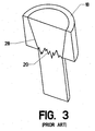
FIG. 3 shows another type ofprior art anchor 18. The version shown does not include a straight portion. A relatively sharp corner is presentproximate potting transition 20. This sharp corner exacerbates the problem seen inFIG. 2 , since the sharp corner may actually cut synthetic strands which are forced against it (Solidified potting compound often creates a very sharp edge). -
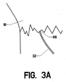
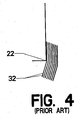
FIG. 3A shows a greatly magnified view ofpotting transition 20. The portion of thestrand 32 lying withinpotted region 16 is held in alignment. Where it exits the hardened potting compound, however, it undergoes an immediate sharp bend. This bend producesstress concentration 66.FIG. 3A represents a very uniform ("good") potting transition. However, the reader will perceive how substantial stress concentration in individual strands can nevertheless occur.FIG. 4 shows the kinking of the individual fibers against a sharp corner where they exit an anchor. Strands at this point are subject to axial compression and bending compression. Such lateral loading are often cyclic in nature, resulting in "flex fatigue" (a condition of accumulating plastic deformation or outright breakage of the individual cable strands). - The strands actually forced against the corner may even be cut. Synthetic cable strands have little cut resistance in comparison to wire rope strands. This fact represents yet another difference between synthetic cables and wire ropes. Strand cutting is a much larger concern for synthetic cables.
- Looking now at
FIG. 5 , the reader will note that thepotting transition 20 is typically irregular in shape, since the infusion of the liquid potting compound through the strands may not be uniformly planar. A portion of hardened potting compound can extend into the freely flexing region of cable near the cable's centerline. This portion often breaks free when the cable is flexed laterally. The existence of the solid region - even when broken free - tends to kink and abrade the cable's strands. Some prior art anchors have included features which could mitigate the aforementioned problems somewhat (at least insofar as they reduce an edge actually cutting into the cable). These features are typically the result of manufacturing convenience or cosmetics, rather than any specific attempt to address the problem of flexural loads.FIG. 6 shows ananchor 18 having asmall fillet 24 around its lower edge (the fillet joins the lower surface and, in this case, the wall of straight portion 38). (Throughout this disclosure, directional terms such as "upper" and "lower" will be understood to refer only to the orientation shown in the view. The devices disclosed will obviously function in any orientation). -
FIG. 7 shows ananchor 18 having asmall chamfer 26 around its lower edge. Such a chamfer is sometimes added to prevent a sharp corner existing at the bottom of expanding cavity 28 (For an anchor having no straight portion, this feature can be particularly important). Such fillets and chamfers have traditionally been added to facilitate machining of the anchors on a lathe or automatic screw machine. Those skilled in the art will know that a sharp corner at the mouth of a bore is undesirable for such machining. - While some flex-mitigating features are found in the prior art terminations, they do not readily accommodate substantial lateral flexing of the cable. Thus, when such terminations are attached to an object, the attachment must allow the anchor to move freely so that it remains aligned with the cable. Suitable attachments include ball and socket joints. However, it is often desirable to attach the anchor to an object without allowing any movement. An example would be an externally threaded anchor which is threaded into a hole in a plate. Once installed, the anchor will be rigidly held.
- The prior art includes certain strain-relieving devices.
FIG. 16 shows the addition of asoft boot 44 encircling the portion ofcable 10 which is immediately adjacent to anchor 18. Made of a pliable material - such as a hard rubber - the soft boot can reduce strand kinking.FIG. 17 shows another type of boot - designated asexternal boot 46. This version attaches to the outside surface ofanchor 18, while still surrounding the portion of the cable which is adjacent to the anchor. - Unfortunately, it is difficult to design a soft boot which can accommodate the different loads and different bending angles which can be placed on a cable.
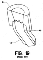
FIG. 18 shows a soft boot using a relatively stiff material. The cable tends to bend near the exit of the boot, causingbend point 48. Thus, the unwanted bend has merely been shifted downward rather than eliminated. - In order to reduce this phenomenon, the designer will often substitute a more pliable compound. Such a pliable compound has been used in
FIG. 19 . However, at higher loads or angles, abend point 48 still results, albeit in a higher location. The reader will thereby appreciate the difficulty in optimizing the boot stiffness using the prior art approach. Reference also is a directed towards examples of the prior art, namely,DE 19546244 ,FR 1447862 JP 04258403 DE 19546244 discloses an arrangement for clamping a metal wire in a holder but it uses a system which relies on a clamping force on the cable generated by encapsulating an expanded end of the cable in a part of the holder having a conical cross-section.FR 1447862 JP 0435840 - The present invention seeks to provide terminations having features which reduce and control stress in the transition between the portion of the cable locked within the termination and the freely flexing region of a cable when the cable flexes literally with respect to the anchor.
- According to the present invention there is provided a flex-accommodating cable termination on an end of a synthetic cable, as defined and claimed in claim 1.
- The invention will now be described by way of example, with reference to the drawings, in which only
figures 22 and23 illustrate the invention. In detail: -
FIG. 1 is a sectional perspective view, showing a prior art termination. -
FIG. 2 is a sectional perspective view, showing bending in a prior art termination. -
FIG. 3 is a sectional perspective view, showing a common prior art anchor. -
FIG. 3A is a detail view, showing the bending of an individual strand. -
FIG. 4 is a detail view, showing strands bending around a corner. -
FIG. 5 is a sectional perspective view, showing an irregular potting transition. -
FIG. 6 is a sectional perspective view, showing manufacturing features of the prior art. -
FIG. 7 is a sectional perspective view, showing manufacturing features of the prior art. -
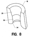
FIG. 8 is a sectional perspective view, showing one embodiment not in accordance with the claimed invention. -
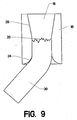
FIG. 9 is a sectional elevation view ofFigure 8 , showing a cable in place, -
FIG. 10 is a sectional elevation view, showing one embodiment not in accordance with the claimed invention. -
FIG. 11 is a sectional elevation view, showing one embodiment not in accordance with the claimed invention. -
FIG. 12 is a sectional elevation view, showing one embodiment not in accordance with the claimed invention. -
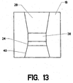
FIG. 13 is a sectional elevation view, showing one embodiment not in accordance with the claimed invention. -
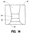
FIG. 14 is a sectional elevation view, showing one embodiment not in accordance with the claimed invention. -
FIG. 15 is a sectional elevation view, showing one embodiment not in accordance with the claimed invention. -
FIG. 16 is a sectional perspective view, showing a prior art boot. -
FIG. 17 is a sectional perspective view, showing a prior art boot. -
FIG. 18 is a sectional perspective view, showing a prior art boot. -
FIG. 19 is a sectional perspective view, showing a prior art boot. -
FIG. 20 is a sectional elevation view, showing one embodiment not in accordance with the claimed invention. -
FIG. 21 is a sectional elevation view, showing one embodiment not in accordance with the claimed invention. -
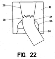
FIG. 22 is a sectional elevation view, showing one embodiment of the present invention. -
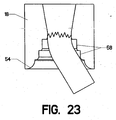
FIG. 23 is a sectional elevation view, showing one embodiment of the present invention. -
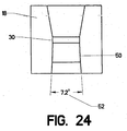
FIG. 24 is a sectional elevation view, showing one embodiment not in accordance with the claimed invention. -
FIG. 25 is a sectional elevation view, showing one embodiment not in accordance with the claimed invention. -
FIG. 26 is a sectional elevation view, showing one embodiment not in accordance with the claimed invention. -
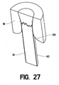
FIG. 27 is a sectional perspective view, showing one embodiment not in accordance with the claimed invention. -
FIG. 28 is a sectional perspective view, showing one embodiment not in accordance with the claimed invention. -
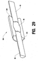
FIG. 29 is a sectional perspective view, showing an intermediate termination. -
FIG. 30 is a sectional perspective view, showing one embodiment not in accordance with the claimed invention. -
FIG. 31 is a sectional perspective view, showing one embodiment not in accordance with the claimed invention. - Referring now to the drawings,
FIG. 8 shows a sectional view of an anchor 18 (Those skilled in the art will know that such anchors are generally radially symmetric). It features an expandingcavity 28 and astraight portion 38 as in the prior art.Circular expansion 34, that is an expansion in which in cross-section as shown is arcuate, is added to the bottom ofstraight portion 38. The radius of this circular expansion is quite large, being at least equal to the radius of the cable to be locked into the anchor. -
FIG. 9 is an elevation sectional view through the anchor ofFIG. 8 , with a cable being installed and flexed laterally. In this particular example, the cable has been locked in the anchor via potting. - Those skilled in the art will also realize that the inventive features disclosed are not dependent upon the use of a particular expanding
cavity 28. By the same token, the potted region can be locked to the anchor by using a straight cavity having threads, serrations, or other mechanically interlocking features. - In
FIG. 9 , pottedregion 16 occupies the expanding cavity and a portion of the straight portion.Potting transition 20 lies well inside the anchor, near the commencement of expanding cavity 28 (though it can lie higher up - well into the expanding cavity - or lower down in the straight portion). A smooth expansion is incorporated proximate the potting transition on the side of the freely flexing portion of the cable (distal to the potted region). This smooth expansion can assume many forms. - The version shown in
FIG. 9 includes a simple arcuate in cross-section expansion, denoted ascircular expansion 34. If theflexible region 30 of the cable is flexed laterally as shown,circular expansion 34 provides a smooth "bending shoulder" around which the cable can bend. Since the circular expansion is radially symmetric, it allows the cable to flex laterally in any direction. The reader will also note thatpotting transition 20, while still irregular, has been moved significantly away from the point where the cable bends. - The inclusion of the circular expansion reduces or prevents the kinking of the cable's strands, as well as reducing axial compression and radial compression. Stress concentrations are thereby minimized, meaning that the load is spread more uniformly throughout the cable's cross section. The circular expansion shown in
FIG. 9 is a simple are having a fixed radius. This radius of the circular expansion should be at least equal to the radius of the cable, though for stiffer cables (or cables having poor resistance to flexural fatigue) it may need to be up to 45 times the radius of the cable. - The use of the structure shown in
FIG. 9 ensures a uniform bending radius for the cable. If, as an example, the cable is bent 5 degrees off the anchor's centerline, the bending radius will be equal to the radius ofcircular expansion 34. If, on the other hand, the cable is bent 45 degrees (as actually shown inFIG. 9 ) the bending radius will still be equal to the radius ofcircular expansion 34. The length of contact between the cable andcircular expansion 34 obviously varies, with the length being far less for the 5 degree bend than the 45 degree bend. The bending radius remains the same, though. This fact allows the cable designer to know what bending radius the completed assembly must endure (within a reasonable range). Since this knowledge allows the prediction of ultimate strength, flexural resistance, etc., it allows the design of a much more predictable cable termination. - Other types of smooth expansions work as well.
FIG. 10 shows ananchor 18 having aparabolic expansion 36. As forFIG. 9 , the potting transition can be placed within the straight portion or up within the lower portion of expandingcavity 28.FIG. 11 shows an anchor having anotherparabolic expansion 36, wherein the defining parabola has different coefficients. Those skilled in the art will know that many different parabolas could be applied. - The term "smooth expansion" is not intended to be limited to tangential curves.
FIG. 12 shows ananchor 18 havinglinear expansion 40. Again, the potting transition can be placed within the straight portion or up within the lower portion of expandingcavity 28. The linear expansion allows the cable to flex laterally proximate the potting transition. While not so effective as the tangential curves, the linear expansion may be easier to manufacture, and may be suitable where only limited lateral flexing is needed. -
Linear expansion 40 can be improved by filleting its intersection with the straight portion. Such an embodiment is shown inFIG. 13 , where afillet 24 has been added to this intersection (where the fillet may be a simple arc, a parabolic arc, or a higher-order curve). This fillet again provides a bending shoulder for the laterally flexing cable. - Those skilled in the art will know that the addition of fillets can be helpful at many points within the anchor.
FIG. 14 shows the addition of afillet 24 at the bottom oflinear expansion 40. Of course, fillets can be added in both locations (the location shown inFIG. 13 and the location shown inFIG. 14 ). Ideally, these fillets should conform to the size constraints stated previously (i.e., having a radius at least as large as the radius of the cable). - The preceding examples have shown the smooth expansion only extending out to the lower surface of the anchor (with "lower" again being understood in the context of the orientation shown in the views). The smooth expansion can be carried further. It can, in fact, be carried around the bottom of the anchor and up the outside surface.
FIG. 15 shows an anchor having acircular expansion 34 extending around to the outside surface. Such an expansion extends the "bending shoulder" so that a cable can be bent all the way around the anchor (up to 180 degrees). If the shoulder is carried over the top of the anchor, the bending angle could even exceed 180 degrees. Applications for such a termination are uncommon, but they do exist. As one example, a cable termination attached to the end of a cylinder rod may extend to the point where it bends the cable back over the anchor as shown. - The anchor geometry can be optimized for a given amount of anticipated lateral cable flexing.
FIG. 20 shows ananchor 18 having a lower expanding portion designated as smooth expansion 50 (which can be a simple arc, a parabola, or higher-order curve). The angular measurement is denoted asangular range 52, which defines the maximum (positive and negative) flexure which can be accommodated before the cable is pressed against a sharp corner. For the embodiment shown inFIG. 20 ,angular range 52 measures 119.6 degrees. Extreme examples are possible.FIG. 24 shows a version having anangular range 52 of only 7.2 degrees, whileFIG. 25 shows a version having an angular range of 180 degrees (90 degrees per side). -
FIG. 21 shows an embodiment having anangular range 52 measuring only 59.8 degrees. It uses similar geometry, but altered dimensional values. The reader will therefore understand that a given anchor geometry can be optimized for a particular application by using a specific angular range. - More complex geometry can also be used.
FIG. 22 shows ananchor 18 according to the invention which includes arelieved portion 56 immediately below a firstcircular expansion 34 and above a secondcircular expansion 34. This embodiment allows a completely free movement of the cable until it bends far enough to contact the circular expansion - For some applications, it may be desirable to have the anchor wall contact the cable at multiple points.
FIG. 23 shows such an embodiment of the invention, which includesstep reliefs 58. These provide point contacts as the cable bends over againstshoulder 54. The size and shape of the step reliefs can be varied to produce many different effects. - The previous embodiments used a straight portion immediately above the expanding portion where the cable exits the anchor. This straight portion need not be entirely straight.
FIG. 26 shows an anchor having a "straight"portion 38 which is not purely cylindrical.Parabolic expansion 36 actually extends all the way up to expandingcavity 28. The portion right next to expandingcavity 28 is almost flat (It asymptotically approaches the vertical). It then smoothly blends into a rapidly expanding portion near the bottom of the anchor. The nearly-vertical portion of the parabolic side wall serves the purpose of the straight portion found in the other versions. -
FIG. 27 shows acable 10 which is encased by anjacket 60.Smooth expansion 50 allows the jacket to bend without abrading or kinking. Such a jacket binds the cable strands together to preserve the circular cross-sectional shape when the cable is flexed. This binding helps to eliminate the problem of uneven load sharing between strands and the creation of stress concentrations (The reader will recall illustrations of this scenario inFIGS. 2 and3 ). - Of course, the jacket does not provide a smooth transition acting alone. It is the combination of the jacket - which substantially maintains the circular cross section - and the
smooth expansion 50, around which the jacketed cable bends. Thus, these elements must be sized to interact appropriately. The radius of the smooth expansion is ideally greater than the radius of the cable. The jacket material is preferably pliable enough to bend around the expansion without kinking. - The term "jacket" can include a tape wrap, a shrink wrap tubing, an extruded plastic, a stranded braid ("over-braid"), an over-molded polymer, a string wrap, or other known binding techniques. The jacket can be applied over the length of the entire cable, over a short length in the proximity of the termination, or any length in between.
- Although the illustrations show radially symmetric terminations, the reader should note that not all embodiments need to be radially symmetric. In some applications, it will be apparent that the cable will flex only in one plane. It may even be desirable to inhibit flexing out of this plane.
FIG. 28 shows an anchor having an expansion which is not radially symmetric. Slottedexpansion 62 allows the cable to flex freely in only one plane. - The preceding examples disclose a termination placed on an end of a cable. The principles disclosed apply equally to terminations placed somewhere between the two ends of a cable.
FIG. 29 showsintermediate termination 64. The central portion of the cable is potted into the termination. It has twocircular expansions 34, one on each end. The two circular expansions allow both the exiting cable segments to flex laterally with respect tointermediate termination 64. - Finally, those skilled in the art will realize that the expanding portion of the passage through the anchor could be made as a separate piece in order to accommodate manufacturing concerns.
FIG. 31 shows such an embodiment, withexpansion bell 70 being made as a separate piece fromanchor 18. The expansion bell can include a circular expansion, a parabolic expansion, or any other shape disclosed in the preceding. - Thus, the reader should rightly view all the preceding embodiments of
figures 22 and23 as providing examples of the invention claimed. The scope of the invention should therefore be fixed by the following claims, and not by the examples provided.
Claims (15)
- A flex-accommodating cable termination on an end of a synthetic cable, including:a. an anchor (18), having a first side and a second side;b. a passage (28, 38) passing completely through said anchor (18) from said first side to said second side;c. said passage (28, 38) including a cable locking region (16) proximate said second side of said anchor;d. cable locking means for locking said cable to said anchor at said cable locking region (16), so that said cable is divided into a locked portion held within said cable locking region (16) and a freely flexing portion extending out said first side of
said anchor (18);e. said passage (28, 38) including a first smoothly curved expansion (34) joining said passage (28, 38) to said first side of said anchor (18);f. a passage portion (38) between said cable locking region and said first smoothly curved expansion; andg. wherein said freely flexing portion of said cable (10) lying proximate said first smoothly curved expansion (34) is completely unencumbered so that it can bend around said first smoothly curved expansion (34) when said freely flexing portion is angularly offset from said anchor (18), characterized in that a passage portion (56) between said first smoothly curved expansion (34) and said cable locking region (16) is relieved; and second smoothly curved expansion (34) is located between said relieved portion (56) and said cable locking region (16). - A flex-accommodating cable termination as claimed in claim 1, wherein said passage portion (38) is at least twice as long as the radius of said cable (10).
- A flex-accommodating cable termination as claimed in claim 1 or 2, wherein said cable locking means comprises potting said end of said cable (10) into said cable locking region (28) using a cross-linking adhesive.
- A flex-accommodating cable termination as claimed in claim 1, 2 or 3, wherein said first smoothly curved expansion (34) is a circular expansion having a radius at least as large as the radius of said cable (10).
- A flex-accommodating cable termination as claimed in any one of claims 1 to 3, wherein said first smoothly curved expansion (36) has a parabolic profile.
- A flex-accommodating cable termination as claimed in any one of the preceding claims, wherein said passage portion (38) is straight.
- A flex-accommodating cable termination as claimed in any one of the preceding claims, wherein
said cable locking region (28) includes a further expansion, having a small portion and a large portion, wherein said large portion opens into said second side of said anchor (18), and
said passage including a straight portion connected to said small portion of said further expansion. - A flex-accommodating cable termination as claimed in claim 1 wherein said passage further comprises a straight portion between said cable locking region (16) and said second smoothly curved expansion (34).
- A flex-accommodating cable termination as claimed in any one of claims 1 to 3 or any one of claims 5 to 8 when dependent thereon, wherein said first and second smoothly curved expansions have a parabolic profile.
- A flex-accommodating cable termination as claimed in any one of claims 1 to 4 or any one of claims 6 to 8 when dependent thereon, wherein said first and second smoothly curved expansions are circular expansions having radii at least as large as the radius of said cable.
- A flex-accommodating cable termination according to any one of the preceding claims, wherein
said passage includes a cable locking region (16) intermediate said first and second sides,
cable locking means adapted to lock an intermediate point of said cable to said anchor at said cable locking region, so that said cable is divided into a locked portion held within said cable locking region, a first freely flexing portion extending out said first side of said anchor, and a second freely flexing portion extending out said second side of said anchor;
said first smoothly curved expansion (34) joining said passage to said first side of said anchor;
a further smoothly curved expansion (34) joining said passage to said second side of said anchor;
wherein said first freely flexing portion of said cable lying proximate said first smoothly curved expansion is completely unencumbered so that it can bend around said first smoothly curved expansion when said first freely flexing portion is angularly offset from said anchor; and
wherein said second freely flexing portion of said cable lying proximate said further smoothly curved expansion is completely unencumbered so that it can bend around said further smoothly curved expansion when said second freely flexing portion is angularly offset from said anchor. - A flex-accommodating cable termination as claimed in claim 11, wherein said first and further smoothly curved expansions are circular expansions having radii at least as large as the radius of said cable.
- A flex-accommodating cable termination as claimed in claim 10, 11, or 12, wherein said passage further comprises:a first straight portion between said cable locking region (16) and said first smoothly curved expansion (34); anda second straight portion between said cable locking region and said further smoothly curved expansion (34).
- A flex-accommodating cable termination as claimed in claim 13, wherein said first and further smoothly curved expansions (34) have parabolic profiles.
- A flex-accommodating cable termination as claimed in any one of the preceding claims, wherein said cable is constrained by an encasing jacket (60) over at least the portion of said cable proximate the junction between said locked portion and said freely flexing portion or portions.
Applications Claiming Priority (1)
| Application Number | Priority Date | Filing Date | Title |
|---|---|---|---|
| US10/946,283 US7543360B2 (en) | 2004-09-21 | 2004-09-21 | Flex accommodating cable terminations |
Publications (2)
| Publication Number | Publication Date |
|---|---|
| EP1637768A1 EP1637768A1 (en) | 2006-03-22 |
| EP1637768B1 true EP1637768B1 (en) | 2013-12-11 |
Family
ID=34979636
Family Applications (1)
| Application Number | Title | Priority Date | Filing Date |
|---|---|---|---|
| EP04256680.2A Not-in-force EP1637768B1 (en) | 2004-09-21 | 2004-10-28 | Flex accommodating cable terminations |
Country Status (3)
| Country | Link |
|---|---|
| US (2) | US7543360B2 (en) |
| EP (1) | EP1637768B1 (en) |
| PT (1) | PT1637768E (en) |
Families Citing this family (14)
| Publication number | Priority date | Publication date | Assignee | Title |
|---|---|---|---|---|
| US7770265B2 (en) * | 2008-02-06 | 2010-08-10 | Bright Technologies, Llc. | Cable termination with an angularly offset parabolic wall profile |
| US20090205172A1 (en) * | 2008-02-19 | 2009-08-20 | Campbell Richard V | Cable termination with an elliptical wall profile |
| US8793843B2 (en) * | 2010-08-13 | 2014-08-05 | Matthew Khachaturian | Lifting sling grommet connector and method |
| DE102012222627B4 (en) * | 2012-12-10 | 2021-11-04 | Robert Bosch Gmbh | Tubular device for connection to a shaft |
| US9863453B2 (en) | 2013-03-15 | 2018-01-09 | Mitsubishi Polycrystalline Silicon America Corporation (MIPSA) | Mechanical seed coupling |
| JP6032848B2 (en) * | 2013-05-17 | 2016-11-30 | 国立研究開発法人海洋研究開発機構 | Junction structure |
| CN104184001B (en) | 2013-05-24 | 2016-11-23 | 富士康(昆山)电脑接插件有限公司 | Micro coaxial cable connector assembly |
| US10113296B2 (en) * | 2013-10-01 | 2018-10-30 | Bright Technologies, L.L.C. | Dragline bucket rigging system |
| US10651637B2 (en) | 2014-03-21 | 2020-05-12 | Quanta Associates, L.P. | Flexible electrical isolation device |
| US9394033B2 (en) | 2014-04-17 | 2016-07-19 | Pgs Geophysical As | Flexible rope termination device |
| USD803031S1 (en) * | 2015-06-24 | 2017-11-21 | Daiwa Kasei Kogyo Kabushiki Kaisha | Clip |
| CA3038052A1 (en) * | 2016-09-23 | 2018-03-29 | Richard V. Campbell | Inverted injection method of affixing a termination to a tensile member |
| US10962088B2 (en) * | 2018-05-10 | 2021-03-30 | Richard V. Campbell | Potting neck enhancement |
| US11378159B2 (en) * | 2018-06-01 | 2022-07-05 | Bright Technologies, Llc | Wicking termination system |
Family Cites Families (8)
| Publication number | Priority date | Publication date | Assignee | Title |
|---|---|---|---|---|
| FR1376395A (en) * | 1963-12-09 | 1964-10-23 | Fitting for flexible tensioner | |
| FR1447862A (en) * | 1965-09-28 | 1966-07-29 | Cable blocking and anchoring | |
| JP2909233B2 (en) * | 1991-02-12 | 1999-06-23 | 神鋼鋼線工業株式会社 | Cable support device |
| US5369849A (en) * | 1993-03-25 | 1994-12-06 | Fargo Mfg. Company, Inc. | Cable gripping unit with spring biased jaw segments |
| DE19546244C1 (en) * | 1995-12-12 | 1997-06-05 | Ver Drahtseilwerke Gmbh | Terminating wire ropes reducing wire breaks at the joint |
| US5718532A (en) * | 1996-05-29 | 1998-02-17 | Massachusetts Institute Of Technology | Device and method for terminating flexible tensile strength members |
| US6017165A (en) * | 1998-01-15 | 2000-01-25 | Sorkin; Felix L. | Wedge-receiving cavity for an anchor body of a post-tension anchor system |
| US20040101681A1 (en) * | 2002-11-21 | 2004-05-27 | Campbell Richard Vest | Filler potting cable termination system and process |
-
2004
- 2004-09-21 US US10/946,283 patent/US7543360B2/en active Active
- 2004-10-28 EP EP04256680.2A patent/EP1637768B1/en not_active Not-in-force
- 2004-10-28 PT PT42566802T patent/PT1637768E/en unknown
-
2008
- 2008-12-09 US US12/316,048 patent/US7669294B2/en active Active
Also Published As
| Publication number | Publication date |
|---|---|
| US7669294B2 (en) | 2010-03-02 |
| US7543360B2 (en) | 2009-06-09 |
| PT1637768E (en) | 2014-03-28 |
| US20060062525A1 (en) | 2006-03-23 |
| EP1637768A1 (en) | 2006-03-22 |
| US20090178244A1 (en) | 2009-07-16 |
Similar Documents
| Publication | Publication Date | Title |
|---|---|---|
| US7669294B2 (en) | Flex accommodating cable terminations | |
| CA2860164C (en) | Method of terminating a stranded synthetic filament cable | |
| CA2769575C (en) | End anchoring structure and method for fiber-reinforced plastic filament body | |
| US9252573B2 (en) | Draw-in wire tip with a base part | |
| US20200002947A1 (en) | Stranded cable wedge | |
| US10184591B2 (en) | Cable suspension clamp | |
| US4596486A (en) | Cable termination | |
| CZ40698A3 (en) | PENDANT CLAMP FOR SUSPENDING CONDUCTORS OF HIGH-VOLTAGE FREE CABLES OF AT LEAST 52 kV ONTO A LOAD-BEARING STRUCTURE | |
| AU2009215875A1 (en) | Cable termination with an elliptical wall profile | |
| US11378159B2 (en) | Wicking termination system | |
| CN214169673U (en) | Clamping body for anchoring steel strand and steel strand anchoring structure | |
| US11524371B2 (en) | Method of terminating a stranded synthetic filament cable | |
| NZ626338B2 (en) | Method of terminating a stranded synthetic filament cable | |
| JPH0424923B2 (en) | ||
| JPS6225814A (en) | Retainer construction of optical compound aerial ground wire |
Legal Events
| Date | Code | Title | Description |
|---|---|---|---|
| PUAI | Public reference made under article 153(3) epc to a published international application that has entered the european phase |
Free format text: ORIGINAL CODE: 0009012 |
|
| AK | Designated contracting states |
Kind code of ref document: A1 Designated state(s): AT BE BG CH CY CZ DE DK EE ES FI FR GB GR HU IE IT LI LU MC NL PL PT RO SE SI SK TR |
|
| AX | Request for extension of the european patent |
Extension state: AL HR LT LV MK |
|
| 17P | Request for examination filed |
Effective date: 20060922 |
|
| AKX | Designation fees paid |
Designated state(s): AT BE BG CH CY CZ DE DK EE ES FI FR GB GR HU IE IT LI LU MC NL PL PT RO SE SI SK TR |
|
| 17Q | First examination report despatched |
Effective date: 20061207 |
|
| GRAP | Despatch of communication of intention to grant a patent |
Free format text: ORIGINAL CODE: EPIDOSNIGR1 |
|
| INTG | Intention to grant announced |
Effective date: 20130606 |
|
| GRAS | Grant fee paid |
Free format text: ORIGINAL CODE: EPIDOSNIGR3 |
|
| GRAA | (expected) grant |
Free format text: ORIGINAL CODE: 0009210 |
|
| AK | Designated contracting states |
Kind code of ref document: B1 Designated state(s): AT BE BG CH CY CZ DE DK EE ES FI FR GB GR HU IE IT LI LU MC NL PL PT RO SE SI SK TR |
|
| REG | Reference to a national code |
Ref country code: GB Ref legal event code: FG4D |
|
| REG | Reference to a national code |
Ref country code: CH Ref legal event code: EP |
|
| REG | Reference to a national code |
Ref country code: AT Ref legal event code: REF Ref document number: 644772 Country of ref document: AT Kind code of ref document: T Effective date: 20140115 |
|
| REG | Reference to a national code |
Ref country code: IE Ref legal event code: FG4D |
|
| REG | Reference to a national code |
Ref country code: DE Ref legal event code: R096 Ref document number: 602004043974 Country of ref document: DE Effective date: 20140206 |
|
| REG | Reference to a national code |
Ref country code: NL Ref legal event code: T3 |
|
| REG | Reference to a national code |
Ref country code: PT Ref legal event code: SC4A Free format text: AVAILABILITY OF NATIONAL TRANSLATION Effective date: 20140324 |
|
| REG | Reference to a national code |
Ref country code: SE Ref legal event code: TRGR |
|
| REG | Reference to a national code |
Ref country code: AT Ref legal event code: MK05 Ref document number: 644772 Country of ref document: AT Kind code of ref document: T Effective date: 20131211 |
|
| PG25 | Lapsed in a contracting state [announced via postgrant information from national office to epo] |
Ref country code: FI Free format text: LAPSE BECAUSE OF FAILURE TO SUBMIT A TRANSLATION OF THE DESCRIPTION OR TO PAY THE FEE WITHIN THE PRESCRIBED TIME-LIMIT Effective date: 20131211 |
|
| PG25 | Lapsed in a contracting state [announced via postgrant information from national office to epo] |
Ref country code: AT Free format text: LAPSE BECAUSE OF FAILURE TO SUBMIT A TRANSLATION OF THE DESCRIPTION OR TO PAY THE FEE WITHIN THE PRESCRIBED TIME-LIMIT Effective date: 20131211 Ref country code: CY Free format text: LAPSE BECAUSE OF FAILURE TO SUBMIT A TRANSLATION OF THE DESCRIPTION OR TO PAY THE FEE WITHIN THE PRESCRIBED TIME-LIMIT Effective date: 20131211 |
|
| PG25 | Lapsed in a contracting state [announced via postgrant information from national office to epo] |
Ref country code: EE Free format text: LAPSE BECAUSE OF FAILURE TO SUBMIT A TRANSLATION OF THE DESCRIPTION OR TO PAY THE FEE WITHIN THE PRESCRIBED TIME-LIMIT Effective date: 20131211 Ref country code: BE Free format text: LAPSE BECAUSE OF FAILURE TO SUBMIT A TRANSLATION OF THE DESCRIPTION OR TO PAY THE FEE WITHIN THE PRESCRIBED TIME-LIMIT Effective date: 20131211 |
|
| PG25 | Lapsed in a contracting state [announced via postgrant information from national office to epo] |
Ref country code: CZ Free format text: LAPSE BECAUSE OF FAILURE TO SUBMIT A TRANSLATION OF THE DESCRIPTION OR TO PAY THE FEE WITHIN THE PRESCRIBED TIME-LIMIT Effective date: 20131211 Ref country code: SK Free format text: LAPSE BECAUSE OF FAILURE TO SUBMIT A TRANSLATION OF THE DESCRIPTION OR TO PAY THE FEE WITHIN THE PRESCRIBED TIME-LIMIT Effective date: 20131211 Ref country code: PL Free format text: LAPSE BECAUSE OF FAILURE TO SUBMIT A TRANSLATION OF THE DESCRIPTION OR TO PAY THE FEE WITHIN THE PRESCRIBED TIME-LIMIT Effective date: 20131211 Ref country code: RO Free format text: LAPSE BECAUSE OF FAILURE TO SUBMIT A TRANSLATION OF THE DESCRIPTION OR TO PAY THE FEE WITHIN THE PRESCRIBED TIME-LIMIT Effective date: 20131211 Ref country code: ES Free format text: LAPSE BECAUSE OF FAILURE TO SUBMIT A TRANSLATION OF THE DESCRIPTION OR TO PAY THE FEE WITHIN THE PRESCRIBED TIME-LIMIT Effective date: 20131211 |
|
| REG | Reference to a national code |
Ref country code: DE Ref legal event code: R097 Ref document number: 602004043974 Country of ref document: DE |
|
| PLBE | No opposition filed within time limit |
Free format text: ORIGINAL CODE: 0009261 |
|
| STAA | Information on the status of an ep patent application or granted ep patent |
Free format text: STATUS: NO OPPOSITION FILED WITHIN TIME LIMIT |
|
| PG25 | Lapsed in a contracting state [announced via postgrant information from national office to epo] |
Ref country code: DK Free format text: LAPSE BECAUSE OF FAILURE TO SUBMIT A TRANSLATION OF THE DESCRIPTION OR TO PAY THE FEE WITHIN THE PRESCRIBED TIME-LIMIT Effective date: 20131211 |
|
| 26N | No opposition filed |
Effective date: 20140912 |
|
| REG | Reference to a national code |
Ref country code: DE Ref legal event code: R097 Ref document number: 602004043974 Country of ref document: DE Effective date: 20140912 |
|
| PG25 | Lapsed in a contracting state [announced via postgrant information from national office to epo] |
Ref country code: SI Free format text: LAPSE BECAUSE OF FAILURE TO SUBMIT A TRANSLATION OF THE DESCRIPTION OR TO PAY THE FEE WITHIN THE PRESCRIBED TIME-LIMIT Effective date: 20131211 |
|
| PG25 | Lapsed in a contracting state [announced via postgrant information from national office to epo] |
Ref country code: MC Free format text: LAPSE BECAUSE OF FAILURE TO SUBMIT A TRANSLATION OF THE DESCRIPTION OR TO PAY THE FEE WITHIN THE PRESCRIBED TIME-LIMIT Effective date: 20131211 Ref country code: LU Free format text: LAPSE BECAUSE OF FAILURE TO SUBMIT A TRANSLATION OF THE DESCRIPTION OR TO PAY THE FEE WITHIN THE PRESCRIBED TIME-LIMIT Effective date: 20141028 |
|
| REG | Reference to a national code |
Ref country code: CH Ref legal event code: PL |
|
| REG | Reference to a national code |
Ref country code: IE Ref legal event code: MM4A |
|
| PG25 | Lapsed in a contracting state [announced via postgrant information from national office to epo] |
Ref country code: LI Free format text: LAPSE BECAUSE OF NON-PAYMENT OF DUE FEES Effective date: 20141031 Ref country code: CH Free format text: LAPSE BECAUSE OF NON-PAYMENT OF DUE FEES Effective date: 20141031 |
|
| REG | Reference to a national code |
Ref country code: FR Ref legal event code: PLFP Year of fee payment: 12 |
|
| PG25 | Lapsed in a contracting state [announced via postgrant information from national office to epo] |
Ref country code: IE Free format text: LAPSE BECAUSE OF NON-PAYMENT OF DUE FEES Effective date: 20141028 |
|
| PG25 | Lapsed in a contracting state [announced via postgrant information from national office to epo] |
Ref country code: BG Free format text: LAPSE BECAUSE OF FAILURE TO SUBMIT A TRANSLATION OF THE DESCRIPTION OR TO PAY THE FEE WITHIN THE PRESCRIBED TIME-LIMIT Effective date: 20131211 |
|
| PG25 | Lapsed in a contracting state [announced via postgrant information from national office to epo] |
Ref country code: IT Free format text: LAPSE BECAUSE OF FAILURE TO SUBMIT A TRANSLATION OF THE DESCRIPTION OR TO PAY THE FEE WITHIN THE PRESCRIBED TIME-LIMIT Effective date: 20131211 Ref country code: GR Free format text: LAPSE BECAUSE OF FAILURE TO SUBMIT A TRANSLATION OF THE DESCRIPTION OR TO PAY THE FEE WITHIN THE PRESCRIBED TIME-LIMIT Effective date: 20140312 |
|
| PG25 | Lapsed in a contracting state [announced via postgrant information from national office to epo] |
Ref country code: HU Free format text: LAPSE BECAUSE OF FAILURE TO SUBMIT A TRANSLATION OF THE DESCRIPTION OR TO PAY THE FEE WITHIN THE PRESCRIBED TIME-LIMIT; INVALID AB INITIO Effective date: 20041028 Ref country code: TR Free format text: LAPSE BECAUSE OF FAILURE TO SUBMIT A TRANSLATION OF THE DESCRIPTION OR TO PAY THE FEE WITHIN THE PRESCRIBED TIME-LIMIT Effective date: 20131211 |
|
| REG | Reference to a national code |
Ref country code: FR Ref legal event code: PLFP Year of fee payment: 13 |
|
| REG | Reference to a national code |
Ref country code: FR Ref legal event code: PLFP Year of fee payment: 14 |
|
| REG | Reference to a national code |
Ref country code: FR Ref legal event code: PLFP Year of fee payment: 15 |
|
| PGFP | Annual fee paid to national office [announced via postgrant information from national office to epo] |
Ref country code: SE Payment date: 20191025 Year of fee payment: 16 Ref country code: DE Payment date: 20191030 Year of fee payment: 16 |
|
| PGFP | Annual fee paid to national office [announced via postgrant information from national office to epo] |
Ref country code: FR Payment date: 20191029 Year of fee payment: 16 |
|
| REG | Reference to a national code |
Ref country code: DE Ref legal event code: R082 Ref document number: 602004043974 Country of ref document: DE Representative=s name: JENSENS IP LIMITED, IE |
|
| REG | Reference to a national code |
Ref country code: DE Ref legal event code: R119 Ref document number: 602004043974 Country of ref document: DE |
|
| REG | Reference to a national code |
Ref country code: SE Ref legal event code: EUG |
|
| PG25 | Lapsed in a contracting state [announced via postgrant information from national office to epo] |
Ref country code: DE Free format text: LAPSE BECAUSE OF NON-PAYMENT OF DUE FEES Effective date: 20210501 Ref country code: FR Free format text: LAPSE BECAUSE OF NON-PAYMENT OF DUE FEES Effective date: 20201031 |
|
| PG25 | Lapsed in a contracting state [announced via postgrant information from national office to epo] |
Ref country code: SE Free format text: LAPSE BECAUSE OF NON-PAYMENT OF DUE FEES Effective date: 20201029 |
|
| PGFP | Annual fee paid to national office [announced via postgrant information from national office to epo] |
Ref country code: NL Payment date: 20210422 Year of fee payment: 17 |
|
| PGFP | Annual fee paid to national office [announced via postgrant information from national office to epo] |
Ref country code: GB Payment date: 20211007 Year of fee payment: 18 Ref country code: PT Payment date: 20211007 Year of fee payment: 18 |
|
| REG | Reference to a national code |
Ref country code: NL Ref legal event code: MM Effective date: 20211101 |
|
| PG25 | Lapsed in a contracting state [announced via postgrant information from national office to epo] |
Ref country code: NL Free format text: LAPSE BECAUSE OF NON-PAYMENT OF DUE FEES Effective date: 20211101 |
|
| GBPC | Gb: european patent ceased through non-payment of renewal fee |
Effective date: 20221028 |
|
| PG25 | Lapsed in a contracting state [announced via postgrant information from national office to epo] |
Ref country code: PT Free format text: LAPSE BECAUSE OF NON-PAYMENT OF DUE FEES Effective date: 20230428 |
|
| PG25 | Lapsed in a contracting state [announced via postgrant information from national office to epo] |
Ref country code: GB Free format text: LAPSE BECAUSE OF NON-PAYMENT OF DUE FEES Effective date: 20221028 |