EP1637242A1 - Large strain introducing working method and caliber rolling device - Google Patents
Large strain introducing working method and caliber rolling device Download PDFInfo
- Publication number
- EP1637242A1 EP1637242A1 EP04734149A EP04734149A EP1637242A1 EP 1637242 A1 EP1637242 A1 EP 1637242A1 EP 04734149 A EP04734149 A EP 04734149A EP 04734149 A EP04734149 A EP 04734149A EP 1637242 A1 EP1637242 A1 EP 1637242A1
- Authority
- EP
- European Patent Office
- Prior art keywords
- caliber
- pass
- strain
- rolling
- flattened
- Prior art date
- Legal status (The legal status is an assumption and is not a legal conclusion. Google has not performed a legal analysis and makes no representation as to the accuracy of the status listed.)
- Granted
Links
Images




Classifications
-
- B—PERFORMING OPERATIONS; TRANSPORTING
- B21—MECHANICAL METAL-WORKING WITHOUT ESSENTIALLY REMOVING MATERIAL; PUNCHING METAL
- B21B—ROLLING OF METAL
- B21B27/00—Rolls, roll alloys or roll fabrication; Lubricating, cooling or heating rolls while in use
- B21B27/02—Shape or construction of rolls
- B21B27/024—Rolls for bars, rods, rounds, tubes, wire or the like
-
- B—PERFORMING OPERATIONS; TRANSPORTING
- B21—MECHANICAL METAL-WORKING WITHOUT ESSENTIALLY REMOVING MATERIAL; PUNCHING METAL
- B21B—ROLLING OF METAL
- B21B1/00—Metal-rolling methods or mills for making semi-finished products of solid or profiled cross-section; Sequence of operations in milling trains; Layout of rolling-mill plant, e.g. grouping of stands; Succession of passes or of sectional pass alternations
- B21B1/16—Metal-rolling methods or mills for making semi-finished products of solid or profiled cross-section; Sequence of operations in milling trains; Layout of rolling-mill plant, e.g. grouping of stands; Succession of passes or of sectional pass alternations for rolling wire rods, bars, merchant bars, rounds wire or material of like small cross-section
-
- B—PERFORMING OPERATIONS; TRANSPORTING
- B21—MECHANICAL METAL-WORKING WITHOUT ESSENTIALLY REMOVING MATERIAL; PUNCHING METAL
- B21B—ROLLING OF METAL
- B21B1/00—Metal-rolling methods or mills for making semi-finished products of solid or profiled cross-section; Sequence of operations in milling trains; Layout of rolling-mill plant, e.g. grouping of stands; Succession of passes or of sectional pass alternations
- B21B1/16—Metal-rolling methods or mills for making semi-finished products of solid or profiled cross-section; Sequence of operations in milling trains; Layout of rolling-mill plant, e.g. grouping of stands; Succession of passes or of sectional pass alternations for rolling wire rods, bars, merchant bars, rounds wire or material of like small cross-section
- B21B1/18—Metal-rolling methods or mills for making semi-finished products of solid or profiled cross-section; Sequence of operations in milling trains; Layout of rolling-mill plant, e.g. grouping of stands; Succession of passes or of sectional pass alternations for rolling wire rods, bars, merchant bars, rounds wire or material of like small cross-section in a continuous process
-
- B—PERFORMING OPERATIONS; TRANSPORTING
- B21—MECHANICAL METAL-WORKING WITHOUT ESSENTIALLY REMOVING MATERIAL; PUNCHING METAL
- B21B—ROLLING OF METAL
- B21B27/00—Rolls, roll alloys or roll fabrication; Lubricating, cooling or heating rolls while in use
- B21B27/02—Shape or construction of rolls
- B21B27/028—Variable-width rolls
Definitions
- the invention of this application relates to a large strain-introducing working method and a caliber rolling device for use in the working method.
- the caliber rolling method As a steel bar manufacturing method, there has been generally known a caliber rolling method using rolls having caliber grooves. At this time, the caliber shape is coarsely divided into angular (e.g., square or diamond), oval or round types. By combining these calibers properly (in a "pass schedule"), the sectional area can be efficiently reduced and finished to a wire rod of predetermined size. At this time, it is important to find a way to reduce the sectional area efficiently and thereby achieve a predetermined shape precisely.
- the strain or stress introduced in one pass can be released by the recovery/recrystalization of the structure between the passes. This raises a problem that the influences of the strain distribution introduced after one pass upon the strain distribution and the sectional shape after the following pass has not been estimated.
- the invention of this application has an object to solve the aforementioned problems of the prior art and to provide novel technical means for clarifying the influences of the strain distribution introduced in the first pass upon the strain distribution and the shape of the next pass, and for introducing large strain into the entire cross section of the material, particularly at the center of the material.
- a working method of rolling with calibers in two or more continuous passes comprising rolling with a flattened-shaped caliber in a first pass, and subsequently rolling with a square-shaped caliber in a second pass, characterized in that the rolling is performed with a caliber in which the ratio of the minor axis 2A 01 of the first pass flattened shape to the original material width between opposing sides 2A 0 is set to A 01 /A 0 ⁇ 0.75, and in which the ratio of a second pass vertical diagonal dimension 2A s1 to the major axis 2B 01 of the material after the first pass is set to A s1 /B 1 ⁇ 0.75, thereby to introduce a large strain into the material.
- a working method wherein the caliber sets the ratio of the minor axis 2A 01 to the major axis 2B 01 of the flattened caliber in the first pass to be A 01 /B 01 ⁇ 0.4.
- the caliber sets the ratio of the radius of curvature r 01 of the flattened caliber in the first pass to 1.5 times or more of the original material width between opposing sides 2A 0 .
- all the rolling pass schedules include at least one flat-angular caliber.
- a rolling device characterized by comprising a caliber which sets the ratio of the minor axis 2A 01 to the major axis 2B 01 of the flattened caliber to A 01 /B 01 ⁇ 0.4.
- a rolling device comprising a caliber, wherein the radius of curvature r 01 of the flattened caliber is at least 1.5 times the original material width between opposing sides 2A 0 .
- a rolling device rolling with calibers in two or more continuous passes, characterized by comprising a first caliber from among those described above, and also a caliber having a shape different from the first caliber, so that the rolling is carried out with the two calibers.
- the second pass vertical diagonal dimension 2As1 is enlarged, giving preference to the cross sectional shaping, thereby enlarging the ratio AS1/B1 with the major axis 2B 01 of the material after the first pass, the nominal compression ratio then becomes so low that, though satisfactory shaping is achieved, large strain cannot be introduced into the material.
- the invention of this application makes compatible the large strain introduction and the cross sectional shaping.
- the strain and the cross sectional shape to be introduced into the material highly depend upon not only the nominal compression ratio of the first pass but also the constraint which is applied by the shape of the flattened caliber, drawing out along the major axis.
- the ratio between the minor axis dimension and the major axis dimension of the flattened caliber becomes smaller, the nominal reduction in the later second pass can be made larger, thereby having the effect of greater strain introduction.
- it is desired that the ratio (the minor axis dimension / the major axis dimension) of the flattened caliber is 0.4 or less.
- the radius of curvature r 01 of the flattened caliber is small, a large area reducing ratio per pass can be taken but is sharp in the widthwise direction. Even if the nominal pressure drop ratio in the second pass is large, the strain cannot be introduced into the center of the material.
- the radius of curvature r 01 should be at least 1.5 times as large as the original material width between opposing sides 2A 0 . Both the shaping and the large strain introduction are efficiently satisfied at 1.5 times or more, but little change occurs in the influence beyond 5 or 6 times. Therefore, there is no upper limit, but the lower limit of 1.5 times or more is the condition.
- the material, to which the aforementioned rolling method can be applied should not be limited to metal material but can applied to all the bar rods that are manufactured by the groove rolling.
- large strain can be easily introduced efficiently over a wide range into metal material with good hardenability.
- large strain can be introduced more easily into stainless steel having excellent hardenability (a large n value) than into low-carbon steel.
- the large strain required of 1.0 is required at the section center, through a square-flattened-square caliber series (2 pass).
- it is desired that the strain of 1.0 or more is introduced into an area of 60 % or more of the material section. Then, it is possible to form a zone of fine crystal grains of the metal material.
- a test piece was a 24mm square steel bar 24.
- the steel bar is SM490 steel containing 0.15C - 0.3 Si - 1.5 Mn - 0.02 P - 0.005 S - 0.03 Al.
- 2-pass groove rolling was performed with the calibers shown in Fig. 2.
- the initial material was the 24 mm square steel bar shown in Fig. 1(a).
- This steel bar was flattened-rolled (for the first pass), as shown in Fig. 1(b), and was then turned by 90 degrees, and rolled (for the second pass) into the steel bar of 18 mm square by the square caliber of Fig. 1(c).
- the rolling temperature was constant at 500°C, and both the rolls had a diameter of 300 mm and a revolving speed of 160 rpm.
- the roll gap was 3 mm for the flattened caliber shown in Fig. 1 but 2 mm for the square caliber.
- Table 1 enumerates the caliber shapes in the flattened caliber of Examples 1 to 4 and Comparison Example 1, and Fig. 3 is a diagram showing geometrical relations between the original material cross sectional shape and the flattened caliber shapes in those cases.
- Table 1 Flattened Calibers Relations with Original Material Height 2A 01 Width 2B 01 Radius of Curvature r 01 Caliber Ratio A 01 /B 01 A s1 /B 1 A 01 /A 0 r 01 /A 0
- Example 1 12 47.1 64 0.25 0.61 0.50 2.67
- Example 2 16 47.1 46 0.34 0.69 0.67 1.92
- Example 3 18 47.1 40.8 0.38 0.74 0.75 1.70
- Comparison Example 1 20 47.1 36.94 0.42 0.78 0.83 1.54
- Fig. 4 shows a distribution of the strain in the cross section of the material of Example 1.
- the inclined cross-shape zone at the center of Fig. 4 designates the zone having strain of 1.5 or more.
- the area reduction ratio from the material of 24mm square is 53 %.
- the ordinary strain, as calculated from the area reduction ratio, is 0.87, but a strain as large as 1.5 is introduced into 70 % of the cross section by passage through the flattened caliber. An extension of this strain is found from the center toward the four sides.
- the strain of 1.0 or more is introduced into 99% of the cross section, and the strain of 1.8 or more is introduced into 9 %.
- the strain at the cross section center is quite large, 1.81.
- Table 2 gives the strains introduced into the section center and respective proportions of the cross section with strains of 1.0 and 1.8 or more, in the cases of the flattened calibers of Examples 1 to 4 and Comparison Example 1.
- the center strain is less than 1.0, and the proportion of the cross section with strain of 1 or more is less than 60 %.
- Fig. 5 is a graph plotting strain along the z-direction line through the cross section center, after the square rolling when the flattened calibers of Examples 1 to 3 and Comparison Example 1 were used.
- the strain takes the maximum at the section center in Examples 1 to 3, for example: 1.81 in Example 1; 1.34 in Example 2; and 1.09 in Example 3.
- the strain is substantially 0.86 at all positions, smaller than that of Examples 1 to 3.
- the area reduction ratios after two passes of the material are 53 %, 49 % and 51 % in Examples 1 to 3 and 47 % in Comparison 1, respectively, which are not very different; however, the strains actually introduced into the material are different.
- Fig. 6 is a graph plotting relations between the strain introduced into the material centers after the square-flattened caliber rolling (the first pass) and after the subsequent flattened-square rolling (the second pass) and the heights of the square caliber.
- Expression 1 ⁇ ⁇ eq 1 st indicates the strain introduced after the first pass
- Expression 2 ⁇ ⁇ eq 2 nd indicates the strain introduced after the second pass
- Expression 3 ⁇ ⁇ eq 2 nd - ⁇ eq 1 st indicates the strain, which is calculated by subtracting the strain after the first pass from the strain after the second pass, that is, the strain introduced in the second pass. From Fig.
- the strain introduced in the second pass has no change from the flattened caliber height of 20 mm onward.
- the working is performed the more for the larger area reducing ratio so that a large strain has been introduced into the material.
- the larger the strain increase the smaller the area reducing ratio. This is highly influenced by the strain distribution introduced in the first pass.
- Fig. 7 presents diagrams showing cross sectional shapes of Example 1 and Comparison Example 2, which use the same flattened caliber.
- Fig. 7(a) shows the sectional shape of the material after the first pass (i.e., the flattened rolling);
- Fig. 7(b) shows the sectional shape (of Example 1) after the second pass (i.e., the square rolling);
- Fig. 7(c) shows the sectional shape (of Comparison 2) in the case where the second pass (i.e., the square rolling) was made after the structure was recovered/recrystallized after the first pass (i.e., the flattened roller) so that the strain and the stress introduced by the first pass became zero again.
- the invention of this application can solve the problems of the prior art and can clarify the influences of the strain distribution introduced in the first pass upon the strain distribution and the shape after the next pass, thus enabling introduction of large strain into the entire sectional area of the material, particularly at the center of the material.
- large strain can be introduced into the center of the material, thereby generating a metal material having a homogeneous cross section structure.
- the invention is useful for generating a metal material having a superfine grain structure, since this structure requires large strain.
- the fact that the strain distribution introduced in the first pass exerts high influences on the magnitude and distribution of the strain after the second pass and also on the sectional shape provides a new technology for satisfactory cross sectional shaping and structure generation at the same time, thereby making a high contribution to the design of future caliber series.
Landscapes
- Engineering & Computer Science (AREA)
- Mechanical Engineering (AREA)
- Physics & Mathematics (AREA)
- Geometry (AREA)
- Metal Rolling (AREA)
- Reduction Rolling/Reduction Stand/Operation Of Reduction Machine (AREA)
Abstract
Description
- The invention of this application relates to a large strain-introducing working method and a caliber rolling device for use in the working method.
- As a steel bar manufacturing method, there has been generally known a caliber rolling method using rolls having caliber grooves. At this time, the caliber shape is coarsely divided into angular (e.g., square or diamond), oval or round types. By combining these calibers properly (in a "pass schedule"), the sectional area can be efficiently reduced and finished to a wire rod of predetermined size. At this time, it is important to find a way to reduce the sectional area efficiently and thereby achieve a predetermined shape precisely.
- In the caliber designs applied in the prior art, however, cares have been taken only in the area reducing ratio and the cross section shaping. This has caused the problem that the metal structure is coarser at the center than on the material surfaces. This is mainly caused by the fact that a strain equivalent to that on the surface is not introduced into the central portion of a material. If, therefore, a large strain can be introduced into the entire material with area reducing ratio and a pass number similar to or smaller than those of the prior art, the structural homogeneity can be enhanced to industrially generate the metal material having a fine grain structure. On the other hand, the caliber designs investigated heretofore are intended for hot working. For this hot working, the strain or stress introduced in one pass can be released by the recovery/recrystalization of the structure between the passes. This raises a problem that the influences of the strain distribution introduced after one pass upon the strain distribution and the sectional shape after the following pass has not been estimated.
- Therefore, the invention of this application has an object to solve the aforementioned problems of the prior art and to provide novel technical means for clarifying the influences of the strain distribution introduced in the first pass upon the strain distribution and the shape of the next pass, and for introducing large strain into the entire cross section of the material, particularly at the center of the material.
- In order to solve the above-specified problems, according to a first aspect of the invention of this application, there is provided a working method of rolling with calibers in two or more continuous passes, comprising rolling with a flattened-shaped caliber in a first pass, and subsequently rolling with a square-shaped caliber in a second pass, characterized in that the rolling is performed with a caliber in which the ratio of the
minor axis 2A01 of the first pass flattened shape to the original material width betweenopposing sides 2A0 is set to A01/A0 ≤ 0.75, and in which the ratio of a second pass verticaldiagonal dimension 2As1 to themajor axis 2B01 of the material after the first pass is set to As1/B1 ≤ 0.75, thereby to introduce a large strain into the material. - According to a second aspect, moreover, there is provided a working method, wherein the caliber sets the ratio of the
minor axis 2A01 to themajor axis 2B01 of the flattened caliber in the first pass to be A01/B01 ≤ 0.4. According to a third aspect, there is provided a working method, wherein the caliber sets the ratio of the radius of curvature r01 of the flattened caliber in the first pass to 1.5 times or more of the original material width betweenopposing sides 2A0. According to a fourth aspect, there is provided a working method, wherein all the rolling pass schedules include at least one flat-angular caliber. - According to a fifth aspect of the Invention of this application, on the other hand, there is provided a rolling device characterized by comprising a caliber which sets the ratio of the
minor axis 2A01 to themajor axis 2B01 of the flattened caliber to A01/B01 ≤ 0.4. - According to a sixth aspect, there is provided a rolling device comprising a caliber, wherein the radius of curvature r01 of the flattened caliber is at least 1.5 times the original material width between
opposing sides 2A0. - According to a seventh aspect, there is provided a rolling device rolling with calibers in two or more continuous passes, characterized by comprising a first caliber from among those described above, and also a caliber having a shape different from the first caliber, so that the rolling is carried out with the two calibers.
-
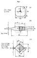
- Fig. 1 presents designations of reference letters in a caliber and a rolling of the invention of this application.
- Fig. 2 presents shapes and sizes of calibers in an embodiment.
- Fig. 3 is a diagram showing shapes of a flattened-shaped caliber in the embodiments.
- Fig. 4 is a diagram showing cross sectional shape and a strain distribution after two passes in Example 1.
- Fig. 5 is a graph plotting strain distributions in the z-direction after two passes.
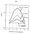
- Fig. 6 is a graph plotting changes in the strain at the center of a material introduced by a pass through various flattened calibers, against the height of the flattened caliber.
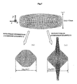
- Fig. 7 presents diagrams showing sectional shapes after a square rolling.
- The invention of this application has the characteristics thus far described and will be described on its mode of embodiment.
- First of all, the characteristics of the caliber of the invention of this application are described with reference to Fig. 1.
- If the nominal reduction ratio (= (2A0 - 2A01)/2A0) at the time of using the flattened-shaped caliber in a first pass is small, hardly any strain is introduced into the center of a material. In order to introduce strain into the cross sectional area of the material by the first pass, therefore, the nominal compression ratio has to be enlarged. This makes it necessary that the ratio of the
minor axis 2A01 used in the flattened caliber of the first pass to the original material width betweenopposing sides 2A0 has to be 0.75 or less. If this ratio is larger than 0.75, the material will flow into the roll gap in the square-shaped caliber of the next pass. The result is not only that the cross sectional shape of the material cannot be held but also that the stored strain is low. If, moreover, the second pass vertical diagonal dimension 2As1 is enlarged, giving preference to the cross sectional shaping, thereby enlarging the ratio AS1/B1 with themajor axis 2B01 of the material after the first pass, the nominal compression ratio then becomes so low that, though satisfactory shaping is achieved, large strain cannot be introduced into the material. - The invention of this application makes compatible the large strain introduction and the cross sectional shaping. The strain and the cross sectional shape to be introduced into the material highly depend upon not only the nominal compression ratio of the first pass but also the constraint which is applied by the shape of the flattened caliber, drawing out along the major axis. As the ratio between the minor axis dimension and the major axis dimension of the flattened caliber becomes smaller, the nominal reduction in the later second pass can be made larger, thereby having the effect of greater strain introduction. For this effect, it is desired that the ratio (the minor axis dimension / the major axis dimension) of the flattened caliber is 0.4 or less.
- If the radius of curvature r01 of the flattened caliber is small, a large area reducing ratio per pass can be taken but is sharp in the widthwise direction. Even if the nominal pressure drop ratio in the second pass is large, the strain cannot be introduced into the center of the material. For the purpose of good shaping and large strain introduction after the next pass, the radius of curvature r01 should be at least 1.5 times as large as the original material width between
opposing sides 2A0. Both the shaping and the large strain introduction are efficiently satisfied at 1.5 times or more, but little change occurs in the influence beyond 5 or 6 times. Therefore, there is no upper limit, but the lower limit of 1.5 times or more is the condition. - By using the flattened caliber, as proposed, in combination with the oval-square or the oval-round caliber series of the prior art, it is possible to form a cross section of highly precise shape and to introduce large strain into the center of the material.
- In the invention of this application, on the other hand, the material, to which the aforementioned rolling method can be applied, should not be limited to metal material but can applied to all the bar rods that are manufactured by the groove rolling. Of these, large strain can be easily introduced efficiently over a wide range into metal material with good hardenability. For example, large strain can be introduced more easily into stainless steel having excellent hardenability (a large n value) than into low-carbon steel. The large strain required of 1.0 is required at the section center, through a square-flattened-square caliber series (2 pass). Moreover, it is desired that the strain of 1.0 or more is introduced into an area of 60 % or more of the material section. Then, it is possible to form a zone of fine crystal grains of the metal material.
- Thus, the mode of embodiment is described in more detail in connection with the following examples, although the invention should not be limited by the examples.
- A test piece was a 24mm
square steel bar 24. The steel bar is SM490 steel containing 0.15C - 0.3 Si - 1.5 Mn - 0.02 P - 0.005 S - 0.03 Al. 2-pass groove rolling was performed with the calibers shown in Fig. 2. The initial material was the 24 mm square steel bar shown in Fig. 1(a). This steel bar was flattened-rolled (for the first pass), as shown in Fig. 1(b), and was then turned by 90 degrees, and rolled (for the second pass) into the steel bar of 18 mm square by the square caliber of Fig. 1(c). The rolling temperature was constant at 500°C, and both the rolls had a diameter of 300 mm and a revolving speed of 160 rpm. On the other hand, the roll gap was 3 mm for the flattened caliber shown in Fig. 1 but 2 mm for the square caliber. The plastic strain introduced into the test materials by the rolling was calculated by using the general finite element code ABAQUS/Explicit. In the analyses, the stress-strain dependence upon the temperature and the strain speed measured in actual tests was employed as the characteristics of the material. The conditions of contact between the rolls and the test pieces were determined so that the friction coefficient µ = 0.30 under Coulomb conditions. Incidentally, the rolls were rigid. - The flattened caliber used had a
height 2A01 = 12 mm, awidth 2B01 = 47.1 mm and the radius of curvature r01 = 64 mm, as shown in Fig. 2(b). - The flattened caliber used had a
height 2A01 = 16 mm, awidth 2B01 = 47.1 mm and the radius of curvature r01 = 46 mm, as shown in Fig. 2(b). - The flattened caliber used had a
height 2A01 = 18 mm, awidth 2B01 = 47.1 mm and the radius of curvature r01 = 40.8 mm, as shown in Fig. 2(b). - The flattened caliber used had a
height 2A01 = 12 mm, awidth 2B01 = 32.7 mm and the radius of curvature r01 = 32 mm, as shown in Fig. 2(b). - The flattened caliber used had a
height 2A01 = 20 mm, awidth 2B01 = 47.1 mm and the radius of curvature r01 = 36.94 mm, as shown in Fig. 2(b). - In the flattened caliber shape of Example 1, the strain after the first pass was released so that the material was without stress and strain (only the cross sectional shape was imparted), and the square rolling was then performed.
- Table 1 enumerates the caliber shapes in the flattened caliber of Examples 1 to 4 and Comparison Example 1, and Fig. 3 is a diagram showing geometrical relations between the original material cross sectional shape and the flattened caliber shapes in those cases.
Table 1 Flattened Calibers Relations with Original Material Height 2A01 Width 2B01 Radius of Curvature r01 Caliber Ratio A01/B01 As1/B1 A01/A0 r01/A0 Example 1 12 47.1 64 0.25 0.61 0.50 2.67 Example 2 16 47.1 46 0.34 0.69 0.67 1.92 Example 3 18 47.1 40.8 0.38 0.74 0.75 1.70 Example 4 12 32.7 32 0.37 0.60 0.50 1.33 Comparison Example 1 20 47.1 36.94 0.42 0.78 0.83 1.54 - Fig. 4 shows a distribution of the strain in the cross section of the material of Example 1.
- The inclined cross-shape zone at the center of Fig. 4 designates the zone having strain of 1.5 or more. The area reduction ratio from the material of 24mm square is 53 %. The ordinary strain, as calculated from the area reduction ratio, is 0.87, but a strain as large as 1.5 is introduced into 70 % of the cross section by passage through the flattened caliber. An extension of this strain is found from the center toward the four sides. Moreover, the strain of 1.0 or more is introduced into 99% of the cross section, and the strain of 1.8 or more is introduced into 9 %. Here, the strain at the cross section center is quite large, 1.81.
- Table 2 gives the strains introduced into the section center and respective proportions of the cross section with strains of 1.0 and 1.8 or more, in the cases of the flattened calibers of Examples 1 to 4 and Comparison Example 1. In Comparison Example 1, the center strain is less than 1.0, and the proportion of the cross section with strain of 1 or more is less than 60 %.
Table 2 Strain Area Percentage (%) Center Strain 1.0 or more 1.8 or more Example 1 99.2 8.5 1.81 Example 2 99.4 0.0 1.34 Example 3 84.7 0.0 1.09 Example 4 100.0 16.0 1.62 Comparison Example 1 54.8 0.0 0.86 - Fig. 5 is a graph plotting strain along the z-direction line through the cross section center, after the square rolling when the flattened calibers of Examples 1 to 3 and Comparison Example 1 were used. The strain takes the maximum at the section center in Examples 1 to 3, for example: 1.81 in Example 1; 1.34 in Example 2; and 1.09 in Example 3.
- In Comparison Example 1, the strain is substantially 0.86 at all positions, smaller than that of Examples 1 to 3. The area reduction ratios after two passes of the material are 53 %, 49 % and 51 % in Examples 1 to 3 and 47 % in
Comparison 1, respectively, which are not very different; however, the strains actually introduced into the material are different. - Fig. 6 is a graph plotting relations between the strain introduced into the material centers after the square-flattened caliber rolling (the first pass) and after the subsequent flattened-square rolling (the second pass) and the heights of the square caliber. Here in Fig. 6:

indicates the strain introduced after the first pass;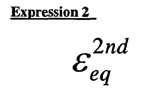
indicates the strain introduced after the second pass; and
indicates the strain, which is calculated by subtracting the strain after the first pass from the strain after the second pass, that is, the strain introduced in the second pass. From Fig. 6, it is found that the strain introduced in the second pass has no change from the flattened caliber height of 20 mm onward. In the prior art, the working is performed the more for the larger area reducing ratio so that a large strain has been introduced into the material. The area reduction ratios in the second pass are 28 %, 32 %, 34 %, 41 %, 41 %, 41 % and 41 %, respectively, for theheights 2A01 of the flattened caliber 2A01 = 12, 14, 18, 20, 22 and 24. In short, the larger the strain increase, the smaller the area reducing ratio. This is highly influenced by the strain distribution introduced in the first pass. The area reducing ratio is constant at 41 % where theheight 2A01 of the flattenedcaliber 2 A01 = 18 mm or more, and the strain is substantially constant at 0.58 for 2A01 = 20 mm or more. If it is hypothesized that when the area reducing ratio is 41%, the strain is homogeneously introduced, that strain is calculated to be 0.60, substantially equal to the strain introduced when 2A01 = 20 mm or more. This means that the strain distribution introduced in the first pass does not contribute to the strain introduction in the second pass. Under the conditions here, it is found that the height of 12 mm of Example 1 increases the strain efficiently (with a small area reduction). In short, the conditions and results of Example 1 show that the strain distribution introduced in the first pass effectively acts on the strain introduced in the second pass. - Fig. 7 presents diagrams showing cross sectional shapes of Example 1 and Comparison Example 2, which use the same flattened caliber. Fig. 7(a) shows the sectional shape of the material after the first pass (i.e., the flattened rolling); Fig. 7(b) shows the sectional shape (of Example 1) after the second pass (i.e., the square rolling); Fig. 7(c) shows the sectional shape (of Comparison 2) in the case where the second pass (i.e., the square rolling) was made after the structure was recovered/recrystallized after the first pass (i.e., the flattened roller) so that the strain and the stress introduced by the first pass became zero again. If the strain distribution introduced into the material after the flattened rolling in the first pass did not exert large influence upon the sectional shape introduced in the second pass, the sectional shape of the material after the square rolling would be unchanged, but this is found from Figs. 7(b) and 7(c) to make a large difference. More specifically, in a caliber series such as square-flattened-square rolling, the sectional shape after the second pass is greatly influenced by the strain distribution introduced in the first pass. Thus, in case the strain from each pass is stored in the material, the relations obtained by the prior arts between the material shape and the square caliber do not apply. This means that the design of the square caliber considering the strain distribution introduced in the first pass plays a very important role.
- As has been detailed here, the invention of this application can solve the problems of the prior art and can clarify the influences of the strain distribution introduced in the first pass upon the strain distribution and the shape after the next pass, thus enabling introduction of large strain into the entire sectional area of the material, particularly at the center of the material.
- According to the invention of this invention, more specifically, large strain can be introduced into the center of the material, thereby generating a metal material having a homogeneous cross section structure. Moreover, the invention is useful for generating a metal material having a superfine grain structure, since this structure requires large strain. Still further, the fact that the strain distribution introduced in the first pass exerts high influences on the magnitude and distribution of the strain after the second pass and also on the sectional shape provides a new technology for satisfactory cross sectional shaping and structure generation at the same time, thereby making a high contribution to the design of future caliber series.
Claims (7)
- A working method of rolling with a caliber rolling of two or more continuous passes, comprising rolling with a flattened-shaped caliber in a first pass, and subsequently rolling with a square-shaped caliber in a second pass, characterized in that the rolling is performed with a caliber in which the ratio of the minor axis 2A01 of the first pass flattened shape to the original material width between opposing sides 2A0 is set to be A01/A0 ≤ 0.75, and in which the ratio of the second pass vertical diagonal dimension 2As1 to the major axis 2B01 of the material after the first pass is set to be As1/B1 ≤ 0.75, thereby introducing a large strain into the material.
- A working method of claim 1, wherein the ratio of the minor axis 2A01 to a major axis 2B01 of the flattened-shaped caliber in the first pass is set to A01/B01 ≤0.4.
- A working method of claim 1 or 2, wherein the caliber sets the ratio of a curvature radius r01 of the flattened-shaped caliber in the first pass is set to be at least 1.5 times of the width across flats 2A0 of the original material.
- A working method of any of claims 1 to 3, wherein all the rolling pass schedules include at least one calibers combination of flat-angular.
- A rolling device comprising a flattened-shaped caliber set the ratio of a minor axis 2A01 to a major axis 2B01 to be A01/B01 ≤ 0.4.
- A rolling device comprising a caliber of claim 5, wherein the radius of curvature r01 of the flattened caliber to 1.5 times or more of the original material width between opposing sides 2A0.
- A rolling device rolling with calibers in two or more continuous passes, characterized by comprising a first caliber of claim 5 or 6, and also a caliber having a shape different from that of the first caliber, so that the rolling is carried out with two calibers.
Applications Claiming Priority (2)
| Application Number | Priority Date | Filing Date | Title |
|---|---|---|---|
| JP2003180291A JP3968435B2 (en) | 2003-05-20 | 2003-05-20 | Large strain introduction processing method and caliber rolling equipment |
| PCT/JP2004/007279 WO2004103591A1 (en) | 2003-05-20 | 2004-05-20 | Large strain introducing working method and caliber rolling device |
Publications (3)
| Publication Number | Publication Date |
|---|---|
| EP1637242A1 true EP1637242A1 (en) | 2006-03-22 |
| EP1637242A4 EP1637242A4 (en) | 2007-04-04 |
| EP1637242B1 EP1637242B1 (en) | 2011-08-10 |
Family
ID=33475459
Family Applications (1)
| Application Number | Title | Priority Date | Filing Date |
|---|---|---|---|
| EP04734149A Expired - Lifetime EP1637242B1 (en) | 2003-05-20 | 2004-05-20 | Large strain introducing working method and caliber rolling device |
Country Status (7)
| Country | Link |
|---|---|
| US (1) | US7647804B2 (en) |
| EP (1) | EP1637242B1 (en) |
| JP (1) | JP3968435B2 (en) |
| KR (1) | KR100701880B1 (en) |
| CN (1) | CN100430160C (en) |
| TW (1) | TWI269675B (en) |
| WO (1) | WO2004103591A1 (en) |
Cited By (1)
| Publication number | Priority date | Publication date | Assignee | Title |
|---|---|---|---|---|
| ITMI20111754A1 (en) * | 2011-09-29 | 2013-03-30 | Danieli Off Mecc | LAMINATION CAGE FOR CALIBRATOR OR REDUCER FOR MULTIPLE PRESSURE POINTS |
Families Citing this family (7)
| Publication number | Priority date | Publication date | Assignee | Title |
|---|---|---|---|---|
| JP5559515B2 (en) * | 2009-11-10 | 2014-07-23 | 大阪精工株式会社 | Metal wire manufacturing method |
| US20110158767A1 (en) * | 2009-12-29 | 2011-06-30 | Ohio Rod Products | Reduced material, content fasteners and systems and methods for manufacturing the same |
| CN102009066B (en) * | 2010-11-17 | 2012-11-14 | 建科机械(天津)股份有限公司 | Passive reducing rolling mill |
| US20120128524A1 (en) * | 2010-11-22 | 2012-05-24 | Chun Young Soo | Steel wire rod having excellent cold heading quality and hydrogen delayed fracture resistance, method of manufacturing the same, and mehod of manufacturing bolt using the same |
| CN102688883A (en) * | 2012-06-14 | 2012-09-26 | 南京钢铁股份有限公司 | Rolling technology for rolling mill with two reversible rollers |
| CN104209318B (en) * | 2014-08-22 | 2016-08-24 | 南京钢铁股份有限公司 | A kind of pass schedule avoiding large-size round steel face crack and roughing technique |
| ITUB20154967A1 (en) * | 2015-10-16 | 2017-04-16 | Danieli Off Mecc | METHOD AND METAL LAMINATING SYSTEM |
Family Cites Families (11)
| Publication number | Priority date | Publication date | Assignee | Title |
|---|---|---|---|---|
| DE1811172A1 (en) * | 1968-11-27 | 1970-06-11 | Demag Ag | Calibration during working of steels |
| JPS5575801A (en) * | 1978-12-04 | 1980-06-07 | Sumitomo Metal Ind Ltd | Rolling method for square steel bar |
| JPS6240904A (en) * | 1985-08-20 | 1987-02-21 | Daido Steel Co Ltd | Rolling method for steel bar |
| DE3689606T2 (en) | 1985-10-22 | 1994-05-19 | Kuraray Co | Manufacturing method for composite pattern refraction type phase gratings. |
| JPS62174703U (en) * | 1986-04-21 | 1987-11-06 | ||
| JPH0763795B2 (en) * | 1988-01-16 | 1995-07-12 | 株式会社神戸製鋼所 | Method for setting control conditions for rolling rolls in manufacturing taper rod |
| JPH04258302A (en) * | 1991-02-07 | 1992-09-14 | Nippon Steel Corp | Sizing rolling method of bar and wire rod |
| CA2236492A1 (en) * | 1997-05-12 | 1999-06-05 | Mario Fabris | Steel mill processing by rhombic reversal reduction rolling |
| JP2000317503A (en) * | 1999-05-14 | 2000-11-21 | Daido Steel Co Ltd | Rolling device and rolling method |
| TW520304B (en) * | 2000-08-21 | 2003-02-11 | Daido Steel Co Ltd | Reversible guideless rolling device |
| CN1132706C (en) * | 2000-10-11 | 2003-12-31 | 李慧峰 | Finish rolling process in wire finish-rolling mill |
-
2003
- 2003-05-20 JP JP2003180291A patent/JP3968435B2/en not_active Expired - Lifetime
-
2004
- 2004-05-20 TW TW093114209A patent/TWI269675B/en not_active IP Right Cessation
- 2004-05-20 WO PCT/JP2004/007279 patent/WO2004103591A1/en not_active Ceased
- 2004-05-20 EP EP04734149A patent/EP1637242B1/en not_active Expired - Lifetime
- 2004-05-20 CN CNB2004800136519A patent/CN100430160C/en not_active Expired - Lifetime
- 2004-05-20 KR KR1020057021978A patent/KR100701880B1/en not_active Expired - Lifetime
- 2004-05-20 US US10/557,412 patent/US7647804B2/en not_active Expired - Lifetime
Cited By (3)
| Publication number | Priority date | Publication date | Assignee | Title |
|---|---|---|---|---|
| ITMI20111754A1 (en) * | 2011-09-29 | 2013-03-30 | Danieli Off Mecc | LAMINATION CAGE FOR CALIBRATOR OR REDUCER FOR MULTIPLE PRESSURE POINTS |
| WO2013045604A1 (en) * | 2011-09-29 | 2013-04-04 | Danieli & C. Officine Meccaniche S.P.A. | Rolling stand for tubes or rounds |
| US10005113B2 (en) | 2011-09-29 | 2018-06-26 | Danieli & C. Officine Meccaniche S.P.A. | Rolling stand for tubes or rounds |
Also Published As
| Publication number | Publication date |
|---|---|
| EP1637242B1 (en) | 2011-08-10 |
| TWI269675B (en) | 2007-01-01 |
| US20060260375A1 (en) | 2006-11-23 |
| JP3968435B2 (en) | 2007-08-29 |
| KR20060012009A (en) | 2006-02-06 |
| CN100430160C (en) | 2008-11-05 |
| EP1637242A4 (en) | 2007-04-04 |
| US7647804B2 (en) | 2010-01-19 |
| WO2004103591A1 (en) | 2004-12-02 |
| CN1791478A (en) | 2006-06-21 |
| JP2004344969A (en) | 2004-12-09 |
| KR100701880B1 (en) | 2007-03-30 |
| TW200505601A (en) | 2005-02-16 |
Similar Documents
| Publication | Publication Date | Title |
|---|---|---|
| EP1637242B1 (en) | Large strain introducing working method and caliber rolling device | |
| EP3006578A1 (en) | Steel sheet for steel belt and process for manufacturing same, and steel belt | |
| EP3549687A1 (en) | Method for manufacturing steel sheet piling | |
| EP2116316B1 (en) | Method for operating a straightener for duplex stainless pipes | |
| RU2391154C2 (en) | Crown roller controlling profile and rolled strip flatness | |
| US8448488B2 (en) | Flat wire manufacturing method of manufacturing flat wire for ring gear | |
| EP2392416B1 (en) | Support roller and roller frame comprising same | |
| DE69228199T2 (en) | METHOD FOR COLD ROLLING METAL STRIP MATERIAL | |
| CN1268449C (en) | Method for rolling finished round steel and method for rolling steel workpieces with circular cross-section | |
| EP2947199A1 (en) | Rubber article reinforcing steel wire and rubber article using same | |
| EP1642988A1 (en) | Warm rolling method | |
| EP0711630A1 (en) | Flat steel wire for side rails of oil ring in internal combustion engine and manufacturing method | |
| DE69816253T2 (en) | Titanium alloy sheet and method of manufacturing the same | |
| EP3698894A1 (en) | Production method for h-beams | |
| KR100343771B1 (en) | A method of preparing a coil spring with good tention | |
| DE102023109502B3 (en) | Method for straightening a metal strip with flatness defects | |
| JPH05212403A (en) | Rolling method for steel bars by 4-roll mill | |
| JPH10166097A (en) | Manufacturing method of irregular cross section | |
| JPH0280102A (en) | Method for rolling h-shape steel | |
| JP3606249B2 (en) | Rolling method of shape steel | |
| JPH0275404A (en) | Roll for drafting web thickness of shape stock | |
| DE102017202909A1 (en) | Method and plant for producing a metallic strip | |
| SU1540879A1 (en) | Method of rolling strips on wide-strip rolling mill | |
| JP2981140B2 (en) | Cold rolling of steel strip | |
| RU2148450C1 (en) | Method for making bent rolled bars |
Legal Events
| Date | Code | Title | Description |
|---|---|---|---|
| PUAI | Public reference made under article 153(3) epc to a published international application that has entered the european phase |
Free format text: ORIGINAL CODE: 0009012 |
|
| 17P | Request for examination filed |
Effective date: 20051216 |
|
| AK | Designated contracting states |
Kind code of ref document: A1 Designated state(s): DE FR GB IT |
|
| DAX | Request for extension of the european patent (deleted) | ||
| RBV | Designated contracting states (corrected) |
Designated state(s): DE FR GB IT |
|
| A4 | Supplementary search report drawn up and despatched |
Effective date: 20070307 |
|
| 17Q | First examination report despatched |
Effective date: 20090130 |
|
| GRAP | Despatch of communication of intention to grant a patent |
Free format text: ORIGINAL CODE: EPIDOSNIGR1 |
|
| GRAS | Grant fee paid |
Free format text: ORIGINAL CODE: EPIDOSNIGR3 |
|
| GRAA | (expected) grant |
Free format text: ORIGINAL CODE: 0009210 |
|
| AK | Designated contracting states |
Kind code of ref document: B1 Designated state(s): DE FR GB IT |
|
| REG | Reference to a national code |
Ref country code: GB Ref legal event code: FG4D |
|
| REG | Reference to a national code |
Ref country code: DE Ref legal event code: R096 Ref document number: 602004033866 Country of ref document: DE Effective date: 20111020 |
|
| PLBE | No opposition filed within time limit |
Free format text: ORIGINAL CODE: 0009261 |
|
| STAA | Information on the status of an ep patent application or granted ep patent |
Free format text: STATUS: NO OPPOSITION FILED WITHIN TIME LIMIT |
|
| 26N | No opposition filed |
Effective date: 20120511 |
|
| REG | Reference to a national code |
Ref country code: DE Ref legal event code: R097 Ref document number: 602004033866 Country of ref document: DE Effective date: 20120511 |
|
| REG | Reference to a national code |
Ref country code: FR Ref legal event code: PLFP Year of fee payment: 13 |
|
| REG | Reference to a national code |
Ref country code: FR Ref legal event code: PLFP Year of fee payment: 14 |
|
| REG | Reference to a national code |
Ref country code: FR Ref legal event code: PLFP Year of fee payment: 15 |
|
| REG | Reference to a national code |
Ref country code: DE Ref legal event code: R082 Ref document number: 602004033866 Country of ref document: DE Representative=s name: DEHNS GERMANY PARTNERSCHAFT MBB, DE Ref country code: DE Ref legal event code: R082 Ref document number: 602004033866 Country of ref document: DE Representative=s name: DEHNSGERMANY PARTNERSCHAFT VON PATENTANWAELTEN, DE |
|
| PGFP | Annual fee paid to national office [announced via postgrant information from national office to epo] |
Ref country code: IT Payment date: 20230526 Year of fee payment: 20 Ref country code: FR Payment date: 20230525 Year of fee payment: 20 Ref country code: DE Payment date: 20220620 Year of fee payment: 20 |
|
| PGFP | Annual fee paid to national office [announced via postgrant information from national office to epo] |
Ref country code: GB Payment date: 20230523 Year of fee payment: 20 |
|
| REG | Reference to a national code |
Ref country code: DE Ref legal event code: R071 Ref document number: 602004033866 Country of ref document: DE |
|
| REG | Reference to a national code |
Ref country code: GB Ref legal event code: PE20 Expiry date: 20240519 |
|
| PG25 | Lapsed in a contracting state [announced via postgrant information from national office to epo] |
Ref country code: GB Free format text: LAPSE BECAUSE OF EXPIRATION OF PROTECTION Effective date: 20240519 |
|
| PG25 | Lapsed in a contracting state [announced via postgrant information from national office to epo] |
Ref country code: GB Free format text: LAPSE BECAUSE OF EXPIRATION OF PROTECTION Effective date: 20240519 |