EP1637204B1 - Conveyor apparatus - Google Patents
Conveyor apparatus Download PDFInfo
- Publication number
- EP1637204B1 EP1637204B1 EP05254202A EP05254202A EP1637204B1 EP 1637204 B1 EP1637204 B1 EP 1637204B1 EP 05254202 A EP05254202 A EP 05254202A EP 05254202 A EP05254202 A EP 05254202A EP 1637204 B1 EP1637204 B1 EP 1637204B1
- Authority
- EP
- European Patent Office
- Prior art keywords
- vessel according
- guide means
- vessel
- solids
- eductors
- Prior art date
- Legal status (The legal status is an assumption and is not a legal conclusion. Google has not performed a legal analysis and makes no representation as to the accuracy of the status listed.)
- Not-in-force
Links
- 239000007787 solid Substances 0.000 claims abstract description 104
- 238000000034 method Methods 0.000 claims abstract description 44
- 239000012530 fluid Substances 0.000 claims description 29
- 238000011144 upstream manufacturing Methods 0.000 claims description 2
- 239000002245 particle Substances 0.000 abstract description 17
- 239000011343 solid material Substances 0.000 abstract description 2
- 239000004576 sand Substances 0.000 description 11
- 239000007788 liquid Substances 0.000 description 10
- XLYOFNOQVPJJNP-UHFFFAOYSA-N water Substances O XLYOFNOQVPJJNP-UHFFFAOYSA-N 0.000 description 8
- 239000007789 gas Substances 0.000 description 6
- 239000003921 oil Substances 0.000 description 6
- 238000004519 manufacturing process Methods 0.000 description 5
- 239000000203 mixture Substances 0.000 description 5
- 238000000926 separation method Methods 0.000 description 4
- 238000013459 approach Methods 0.000 description 3
- 239000010802 sludge Substances 0.000 description 3
- 239000004215 Carbon black (E152) Substances 0.000 description 2
- 238000009825 accumulation Methods 0.000 description 2
- 230000008901 benefit Effects 0.000 description 2
- 238000004140 cleaning Methods 0.000 description 2
- 238000005260 corrosion Methods 0.000 description 2
- 230000007797 corrosion Effects 0.000 description 2
- 230000009977 dual effect Effects 0.000 description 2
- 230000003628 erosive effect Effects 0.000 description 2
- 229930195733 hydrocarbon Natural products 0.000 description 2
- 150000002430 hydrocarbons Chemical class 0.000 description 2
- 239000007791 liquid phase Substances 0.000 description 2
- 239000013618 particulate matter Substances 0.000 description 2
- 239000012071 phase Substances 0.000 description 2
- 229910000831 Steel Inorganic materials 0.000 description 1
- 230000001580 bacterial effect Effects 0.000 description 1
- 238000009395 breeding Methods 0.000 description 1
- 230000001488 breeding effect Effects 0.000 description 1
- 239000006227 byproduct Substances 0.000 description 1
- 239000003054 catalyst Substances 0.000 description 1
- 238000005352 clarification Methods 0.000 description 1
- 239000004927 clay Substances 0.000 description 1
- 238000005202 decontamination Methods 0.000 description 1
- 230000003588 decontaminative effect Effects 0.000 description 1
- 230000007423 decrease Effects 0.000 description 1
- 230000000694 effects Effects 0.000 description 1
- 238000009713 electroplating Methods 0.000 description 1
- 238000011010 flushing procedure Methods 0.000 description 1
- 239000000446 fuel Substances 0.000 description 1
- 230000005484 gravity Effects 0.000 description 1
- 230000001771 impaired effect Effects 0.000 description 1
- 238000007373 indentation Methods 0.000 description 1
- 239000000463 material Substances 0.000 description 1
- 230000000737 periodic effect Effects 0.000 description 1
- 230000035699 permeability Effects 0.000 description 1
- 239000000047 product Substances 0.000 description 1
- 238000000746 purification Methods 0.000 description 1
- 239000000376 reactant Substances 0.000 description 1
- 230000000284 resting effect Effects 0.000 description 1
- 239000013535 sea water Substances 0.000 description 1
- 239000013049 sediment Substances 0.000 description 1
- 238000004062 sedimentation Methods 0.000 description 1
- 239000010959 steel Substances 0.000 description 1
- 239000013598 vector Substances 0.000 description 1
- 239000002699 waste material Substances 0.000 description 1
Images


Classifications
-
- B—PERFORMING OPERATIONS; TRANSPORTING
- B01—PHYSICAL OR CHEMICAL PROCESSES OR APPARATUS IN GENERAL
- B01D—SEPARATION
- B01D21/00—Separation of suspended solid particles from liquids by sedimentation
- B01D21/24—Feed or discharge mechanisms for settling tanks
-
- E—FIXED CONSTRUCTIONS
- E21—EARTH OR ROCK DRILLING; MINING
- E21B—EARTH OR ROCK DRILLING; OBTAINING OIL, GAS, WATER, SOLUBLE OR MELTABLE MATERIALS OR A SLURRY OF MINERALS FROM WELLS
- E21B43/00—Methods or apparatus for obtaining oil, gas, water, soluble or meltable materials or a slurry of minerals from wells
- E21B43/34—Arrangements for separating materials produced by the well
- E21B43/35—Arrangements for separating materials produced by the well specially adapted for separating solids
-
- B—PERFORMING OPERATIONS; TRANSPORTING
- B01—PHYSICAL OR CHEMICAL PROCESSES OR APPARATUS IN GENERAL
- B01D—SEPARATION
- B01D21/00—Separation of suspended solid particles from liquids by sedimentation
- B01D21/0039—Settling tanks provided with contact surfaces, e.g. baffles, particles
- B01D21/0045—Plurality of essentially parallel plates
-
- B—PERFORMING OPERATIONS; TRANSPORTING
- B01—PHYSICAL OR CHEMICAL PROCESSES OR APPARATUS IN GENERAL
- B01D—SEPARATION
- B01D21/00—Separation of suspended solid particles from liquids by sedimentation
- B01D21/0039—Settling tanks provided with contact surfaces, e.g. baffles, particles
- B01D21/0069—Making of contact surfaces, structural details, materials therefor
- B01D21/0072—Means for adjusting, moving or controlling the position or inclination of the contact surfaces, e.g. for optimising the particle-liquid separation, for removing the settled particles, for preventing fouling
-
- B—PERFORMING OPERATIONS; TRANSPORTING
- B01—PHYSICAL OR CHEMICAL PROCESSES OR APPARATUS IN GENERAL
- B01D—SEPARATION
- B01D21/00—Separation of suspended solid particles from liquids by sedimentation
- B01D21/24—Feed or discharge mechanisms for settling tanks
- B01D21/245—Discharge mechanisms for the sediments
- B01D21/2472—Means for fluidising the sediments, e.g. by jets or mechanical agitators
Definitions
- This invention relates to conveyor apparatus and particularly though not exclusively to conveyor apparatus for conveying solid material such as sand, from a process vessel.
- Solids often appear as sand, clay or silt. These solids generally originate from the reservoir, but other solids may also be produced such as corrosion by-products from the well tubing and process equipment or frac sand which has been deliberately injected downhole to increase the permeability of the reservoir. The amount, type, size and production variability of the solids produced varies widely from field to field.
- Solids production rates do not have to be particularly high before they begin to affect processing of the well output. For example, solids cause particular problems with process vessels such as gravity separators since the solids settle out in these vessels due to the quiescent environment within the vessels. Typically, as the solids accumulate, the residence times for the liquid phase(s) decline for a given liquid throughput and therefore separation performance is impaired. The solids accumulation in these vessels also forms a good breeding ground for bacterial growth which can cause severe corrosion of the vessel walls.
- US-A-5612003 is not directly concerned with the removal of solids from a vessel but shows the simple use of a single eductor to maintain a fluidised bed of particulate matter (for example a catalyst fuel or a reactant).
- the output of the eductor is fed into the inlet of a cyclone which separates particulate matter and returns it to the fluidised bed.
- US-A-3895927 again discloses the use of a single eductor (described as a “dual ejector").
- the "dual" function of the ejector refers to the use of the ejector both to move mud or solids in a process vessel and also to draw a vacuum on the vessel.
- this document is concerned with avoiding the use of a separate vacuum pump and the associated piping requirements.
- EP-A1-0792950 discloses the use of a plurality of eductors operating independently of one another to discharge solids settled in a vessel having an inclined bottom surface.
- the vessel is used for decontamination or electroplating of metallic articles.
- the eductors are used to prevent "sludge” or other solid particles from piling up in the vessel.
- the eductors (described as “ejectors") are used to move solids to a predetermined place at one side of the vessel.
- US-A-4428841 discloses a housing with multiple eductors which are used for solids cleaning and removal.
- the eductors are used periodically to agitate a "corrugated plate arrangement" which is used in "solids cleaning".
- WO 00/25886 discloses the use of daisy-chained eductors to move solids along a process vessel to a solids outlet.
- FR2378550 discloses a clarification vessel for the separation of particles in order to produce a thickened sludge at the bottom of the vessel.
- US4813157 discloses an apparatus and method for clarifying solids from solids containing liquid with the use of a multilayer baffle system.
- GB630505 discloses an apparatus for the purification of liquids, including a diaphragm comprising a plurality of spaced apart sections each including an inverted 'V'.
- GB2075856 discloses an intrachannel clarifier for producing clarified waste liquid, including a perforated baffle made up of a plurality of spaced apart inverted V.
- WO 89/02775 discloses a sedimentation device Including moveable baffles whereby the settled sludge is flushed away.
- US2973866 discloses a settling tank including baffles inclined away from the direction of fluid flow In the upper level of the tank.
- a process vessel for separating products from oil or gas wells having a solids outlet, and a plurality of eductors positioned within and generally at the bottom of the vessel and arranged in use to move solids generally along the bottom of the vessel towards the solids outlet, the vessel including a first guide means located above the eductors and arranged to restrict upward flow of solids.
- the vessel includes a second guide means located above and/or adjacent the first guide means. This may be arranged to restrict upward flow of solids reflected from the end wall of the vessel or a weir in the vessel.
- the invention also provides in another aspect, guide means for a process vessel comprising a generally flat or curved sheet mountable in a process vessel and including apertures arranged to permit the passage of process solids.
- a method of improving separation of solids in a flowing liquid-solid mix comprising providing a generally planar guide with apertures whereby solids particles are able to pass through the apertures during their downward trajectory but are generally unable to pass back upwardly.
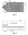
- a vessel 66 has a plurality of eductors 60 which are described in more detail below, located generally at the bottom of the vessel 66.
- the vessel also has a solids outlet 30 to which the eductors 60 direct solids which have settled out of the process liquids in the vessel 66.
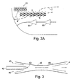
- Process liquids such as oil and water are fed into the vessel 66 and travel generally from right to left in the Figure. As the liquid travels, solids tend to settle out as indicated by dotted line 2 in Figure 2A . Once settled, they are entrained in a flow created by the eductors 60 as described below.
- guide means 4 in this example in the form of a first louvered plate 4 comprising a plurality of baffles 6, is located above the eductors.
- baffles are inclined so that the trajectory of solids particles 2 passes generally parallel to the plane of the baffles 6 as shown in detail in Figure 2A .
- the guide means 4 may instead be formed from a perforated plate, for example, which may also have corrugations arranged to help fluid flow and solids settling.
- the plate may have indentations which desirably may have apertures near or at the lower parts of the recesses.
- the recesses may be generally randomly distributed and/or periodically distributed across the plate.
- the plate 4 is sealed against the wall of the vessel 66 to ensure that solids particles do not escape past the plate.
- the inclination of the baffles 6 is generally of the order of 40 degrees to horizontal. Ideal ranges are between 30 and 50 degrees with a range between 35 and 40 degrees being most preferred.
- the precise angle will depend on the flow velocity through the vessel 66 and the relative mass of particles and viscosity of the process liquid. Generally, the limiting angle of repose of sand on steel is about 35 degrees to horizontal. Thus since it is not desired to have solids (often predominantly sand) resting on the plate 4, the angle is typically kept steeper than 35 degrees. The variability of some of these factors also has an influence on the lateral spacing of the baffles. Wider spaced baffles 6 can accommodate a larger variation in trajectory of solids particles but wider spacing also provides greater opportunity for particles to return to the upper levels of the vessel 66.
- a second guide means having a structure which may be similar to that of the first guide means, such as a louvered plate 10 is located preferably above the first, and with baffles inclined generally in the opposite direction to those of the first plate 4. It will be seen that this second plate 10 substantially prevents such reflected particles from escaping. Such particles then fall back down towards the bottom of the vessel and are ejected through the solids outlet 30.
- first and second guide means located in areas of high sand velocity or momentum. It has been found that if sand velocity drops, there is a tendency for the sand not to be caught by the guide means and instead to be moved by currents such as eddy currents.
- first guide means ideally should be as low in the vessel 66 as possible and the second guide means typically will be a similar distance above the second guide means as the first guide means is above the bottom of the vessel.
- louvered plate approach described above is applicable to any process vessel in which solids are moved along the bottom of a process vessel by some motive means and in which it is undesirable for the solids to re-mix with other liquids in the vessel. Eductors are not therefore essential.
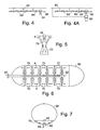
- a typical eductor has a solids inlet 40, a jet inlet 42 and an outlet 44.
- the eductor acts as a jet pump which uses some of the energy from a motive fluid entering the jet inlet 42, to entrain another fluid in order to eject it at a higher pressure than that at which it entered the solids inlet 40.
- the motive fluid is water which is directed into a convergent section 46 of the eductor.
- the motive fluid may, for example, be seawater, produced water (produced from the well) or hydrocarbon.
- the motive fluid entrains the fluid in which the eductor is submerged and as the entrained fluid enters a divergent section 48, some of the kinetic energy of the motive fluid is converted into pressure energy in the diffuser section. This causes the mixture of motive fluid and fluid entering the solids inlet 40 to be discharged at a higher pressure than the eductor suction pressure present at the solids inlet 40.
- the eductor shown actively draws fluid from behind the nozzle 50 of the jet inlet 42 and ejects it out of the divergent section 48.
- a solids inlet may instead or in addition be provided at the convergent section 46; this latter arrangement being particularly useful for the transverse eductors described below.
- Eductors are also known as jet pumps and ejectors. The general principle is that all these devices enable energy from a high pressure source to be used to boost the pressure of low pressure fluids.
- An eductor therefore has at least the following two main benefits:-
- Motive and suction flows may be gas or liquid phase or a mixture of the two. The choice affects the eductor performance.
- the characteristic of increased pressure through the eductor means that eductors may be "daisy-chained", i.e. the output of one eductor provides the input for the next eductor in the chain. This is possible because the solids in the fluid passing through the eductor are both drawn and driven rather than just being driven as in a conventional jetting nozzle.
- Figure 4 shows daisy-chained eductors 60 fed from a jet water manifold 62 and arranged to eject solids entrained in a fluid through a solids discharge port 64.
- a highly efficient solids transport system can be created where flow vectors are restricted to the area of the eductors.
- flow continuity from one eductor to the next should preferably be maintained.
- the total flow output (motive fluid and eductor suction fluid) from all upstream eductors feeding a downstream eductor should ideally equal the suction fluid inlet flow of that downstream eductor.
- a solids jetting flow which is highly localized may be created at the bottom of the vessel. This ensures minimum disturbance to the separator's bulk flow in the upper regions of the housing 66.
- the housing 66 has an inlet 67 for the jet water manifold 62.
- the housing 66 have daisy-chained eductors located at its bottom but also a second set of eductors 70 located along the housing side wall transversely of the daisy-chained eductors 60.
- This second set of transverse eductors 70 fluidize the side wall region and direct the solids to the bottom of the housing.
- the axial eductors 60 transport the solids along the bottom in the direction of the bulk fluid flow in the vessels, to the solids discharge port 64.
- the transverse eductors 70 draw their source generally horizontally from either side along the side wall as shown by arrows A in Figures 5 and 6 and eject the flow to form a high velocity expanding "sheet" preferably achieved by the diffuser section 72 having a high cross-sectional aspect ratio (and arranging for the longer side to be parallel to the side wall).
- the outlet of the transverse eductors 70 is drawn by the axial eductors 60 through about 90° and is then transported axially along the bottom of the housing 66 by the axial eductors 60 to the nearest solids outlet 64.
- transverse eductors may be inclined so that the flow through those eductors has an axial as well as a vertical component. In that case, the outlet of the transverse eductors may be drawn through substantially more or less than 90°.
- the eductors 60' are arranged in a herringbone pattern which feeds solids generally towards the middle of the vessel. This is shown in Figure 12 .
- a typical angle for the herringbone pattern is approximately 45 degrees to the major axis of the vessel 66.
- a preferred range of angles is 80 to 20 degrees and a more preferred range of angles is 60 to 30 degrees.
- the upper, unfluidized solids layer restricts the potential for flow disturbance to occur in the upper regions of the housing.
- one or more outlet eductor 80 may be used to draw fluidized solids from the solids outlet 64.
- the outlet eductor 80 may be supplied with motive fluid from the manifold 62.
- Flow through the solids outlet 64 may also be enhanced by one or more generally vertical eductor inside the housing 66 taking the generally horizontal outlet of the preceding axial eductors 60 and directing it downwardly to the solids outlet 64. This may be used as well as or instead of the outlet eductor 80.
- the process vessel 66 may have more than one solids outlet 64 which may be arranged to receive the output from one or more of the axial eductors 60.
- one or more of this plurality of outlets 64 may be coupled to one or more outlet eductor 80.
- Outlet eductors may be located outside the process vessel.
- outlets 64 The advantage of having several outlets 64 is that the volume which must be drawn out of the axial eductor daisy-chain by the outlet 64 may be controlled. A single outlet at the end of the daisy-chain will be required to accommodate a greater volume of fluidized solids than several outlets at spaced intervals along the daisy-chain.
- outlet eductors greatly enhances the performance of the discharge port 64 by actively drawing material out of the port.
- the arrangement described above provides shorter flushing times, a lower jetting water flow rate and reduced impact to process vessel performance when compared to the prior art arrangements. Furthermore, the probability of sediment being carried into the liquid outlet streams of a separating process vessel is reduced. Also, because the flow of solids is generally parallel to the housing wall, erosion damage to the housing is greatly reduced compared to the prior art arrangement.
- Transverse eductors 70 may be used alone in some applications.
- One such application is in pressurised process vessels.
- the transverse eductor 70 operate to move solids to the bottom of the vessel. When the vessel is opened and depressurised, the depressurisation draws the solids out of the vessel.
- baffles which substantially prevent solids moving up into the higher regions of the vessel to prevent re-mixing with other parts of the mix contained in the vessel.
- process vessel should be taken to include not only the separators described above but any fluid-containing vessel in which solids may accumulate.
- a process vessel typically provides "residence time”. It may for example be a phase separator, or a holding tank. It also may be a pressurised container.
- the process vessel housing 66 may be provided with one or more weir 100 located on the downstream side of a solids outlet 64.
- the weir helps to collect sand adjacent the solids outlet 64 and also helps to prevent disturbance of the upper regions of the housing.
- the plates 10' and 4' need not be horizontal. They may, for example, become close or further away from the vessel floor at different positions along the vessel.
- Figure 10 shows an end view of the vessel and shows a curve on the plate 4.
- the plate may curve in the opposite direction.
- the plates 10 and 4 and 10'and 4' may be adjustable so that the optimum height, inclination and extensiveness over the vessel may be found.
- Performance may be further enhanced by funneling the solids towards the solids outlet.
- This is shown in Figure 1 in which inclined funneling baffles 102 located below the first guide means and extending downwardly reduce the effective width of the vessel near the solids outlet 30.
- one possible angle of the inclination is 43 degrees. Angles in the range 30 to 50 degrees have been found suitable. By angling the baffles 102 in this way, the solids are better directed to the outlet 30 .
- the louvered plate 4 or 10 may be formed from a series of curved baffles 102.
- the curves on the baffles help to guide sand without causing sudden changes in direction.
- Figure 14 shows an alternative configuration in which baffles 104 are curved on only one major surface.
- the spacing between baffles need not be uniform. It may be desirable to have the spacing closer in some areas and wider in others.
Landscapes
- Chemical & Material Sciences (AREA)
- Chemical Kinetics & Catalysis (AREA)
- Life Sciences & Earth Sciences (AREA)
- Engineering & Computer Science (AREA)
- Geology (AREA)
- Mining & Mineral Resources (AREA)
- Physics & Mathematics (AREA)
- Environmental & Geological Engineering (AREA)
- Fluid Mechanics (AREA)
- General Life Sciences & Earth Sciences (AREA)
- Geochemistry & Mineralogy (AREA)
- Devices And Processes Conducted In The Presence Of Fluids And Solid Particles (AREA)
- Separation Of Solids By Using Liquids Or Pneumatic Power (AREA)
- Formation And Processing Of Food Products (AREA)
- Auxiliary Methods And Devices For Loading And Unloading (AREA)
- Screw Conveyors (AREA)
- Fish Paste Products (AREA)
- Manufacturing And Processing Devices For Dough (AREA)
- Silicates, Zeolites, And Molecular Sieves (AREA)
- Liquid Crystal (AREA)
- Physical Water Treatments (AREA)
- Feeding, Discharge, Calcimining, Fusing, And Gas-Generation Devices (AREA)
- Structure Of Belt Conveyors (AREA)
- Chutes (AREA)
Priority Applications (1)
| Application Number | Priority Date | Filing Date | Title |
|---|---|---|---|
| EP10154279A EP2184094A3 (en) | 2004-07-10 | 2005-07-05 | Conveyor apparatus |
Applications Claiming Priority (1)
| Application Number | Priority Date | Filing Date | Title |
|---|---|---|---|
| GB0415521A GB2415922B (en) | 2004-07-10 | 2004-07-10 | Conveyor apparatus |
Related Child Applications (1)
| Application Number | Title | Priority Date | Filing Date |
|---|---|---|---|
| EP10154279.3 Division-Into | 2010-02-22 |
Publications (3)
| Publication Number | Publication Date |
|---|---|
| EP1637204A2 EP1637204A2 (en) | 2006-03-22 |
| EP1637204A3 EP1637204A3 (en) | 2006-06-07 |
| EP1637204B1 true EP1637204B1 (en) | 2010-11-10 |
Family
ID=32865801
Family Applications (2)
| Application Number | Title | Priority Date | Filing Date |
|---|---|---|---|
| EP05254202A Not-in-force EP1637204B1 (en) | 2004-07-10 | 2005-07-05 | Conveyor apparatus |
| EP10154279A Withdrawn EP2184094A3 (en) | 2004-07-10 | 2005-07-05 | Conveyor apparatus |
Family Applications After (1)
| Application Number | Title | Priority Date | Filing Date |
|---|---|---|---|
| EP10154279A Withdrawn EP2184094A3 (en) | 2004-07-10 | 2005-07-05 | Conveyor apparatus |
Country Status (10)
| Country | Link |
|---|---|
| US (1) | US7401704B2 (da) |
| EP (2) | EP1637204B1 (da) |
| AT (1) | ATE487524T1 (da) |
| AU (1) | AU2005203002B2 (da) |
| CA (1) | CA2511701C (da) |
| DE (1) | DE602005024652D1 (da) |
| DK (1) | DK1637204T3 (da) |
| GB (1) | GB2415922B (da) |
| NO (1) | NO329479B1 (da) |
| NZ (1) | NZ541127A (da) |
Families Citing this family (6)
| Publication number | Priority date | Publication date | Assignee | Title |
|---|---|---|---|---|
| CA2669710C (en) * | 2009-06-19 | 2016-01-05 | Pat Page | Sand separation vessel |
| US20120073675A1 (en) * | 2010-09-24 | 2012-03-29 | Strad Energy Services Ltd. | Storage tank system having ease of placement and interconnectivity |
| CN102100979B (zh) * | 2011-01-11 | 2012-10-10 | 东北电力大学 | 可调式浮沉切换固液分离装置 |
| US9434631B2 (en) * | 2014-08-07 | 2016-09-06 | John T. Vlahogeorge | Apparatus for removing material from a body of liquid |
| US9809465B2 (en) | 2014-08-07 | 2017-11-07 | John T. Vlahogeorge | Apparatus for removing material from a body of liquid |
| US10273177B2 (en) | 2014-08-07 | 2019-04-30 | John T. Vlahogeorge | Apparatus for lifting liquid in a body of liquid |
Family Cites Families (22)
| Publication number | Priority date | Publication date | Assignee | Title |
|---|---|---|---|---|
| US2267608A (en) * | 1941-12-23 | Sewage sedimentation system | ||
| FR960160A (da) * | 1947-01-31 | 1950-04-14 | ||
| US2973866A (en) * | 1959-05-14 | 1961-03-07 | Albert L Genter | Settling tank |
| US3013395A (en) * | 1959-07-28 | 1961-12-19 | John A Gaylord | River bottom sand accumulation remover |
| US3895927A (en) | 1971-03-02 | 1975-07-22 | Well Control Inc | Apparatus for the degassification of drilling muds |
| FR2132954A5 (da) * | 1971-04-02 | 1972-11-24 | Degremont | |
| US4067813A (en) * | 1973-11-05 | 1978-01-10 | Pielkenrood-Vinitex B.V. | Compound separation device |
| US4042512A (en) * | 1976-10-27 | 1977-08-16 | Mccarthy Patrick M | Oil water separator |
| CH615597A5 (en) * | 1977-01-26 | 1980-02-15 | Sulzer Ag | Process and apparatus for settling settleable particles contained in liquids |
| CA1160767A (en) * | 1980-05-01 | 1984-01-17 | Joel A. Cerwick | Waste treatment system having integral intrachannel clarifier |
| US4428841A (en) | 1981-01-27 | 1984-01-31 | Engineering Specialties, Inc. | Offshore pollution prevention |
| US4514303A (en) * | 1983-06-09 | 1985-04-30 | Moore Richard P | Sludge traction and desludging system |
| US4816157A (en) * | 1987-05-14 | 1989-03-28 | Jennelle Ernest M | Hydraulic sweep clarifier |
| US4913819A (en) * | 1987-08-28 | 1990-04-03 | Atlantic Richfield Company | Liquid jet solids removal system for process vessels |
| SE458987B (sv) * | 1987-09-22 | 1989-05-29 | K Z Handels Ab | Anordning och foerfarande vid sedimenteringsbassaenger |
| US5547569A (en) * | 1995-01-25 | 1996-08-20 | Hinkle Contracting Corporation | Multiple stage water clarifier |
| WO1997012077A1 (fr) * | 1995-09-28 | 1997-04-03 | Kawasaki Steel Corporation | Procede de dechargememt d'un depot de particules solides et equipement correspondant |
| GB2343128A (en) * | 1998-10-29 | 2000-05-03 | Cyclotech Ltd | Apparatus for conveying solid material within a separator |
| EP1159050B1 (en) * | 1999-03-05 | 2003-05-28 | Shell Internationale Researchmaatschappij B.V. | Three-phase separator |
| US6491830B1 (en) * | 2001-05-16 | 2002-12-10 | Thermaco, Inc. | Kitchen grease removal system |
| NO318865B1 (no) * | 2003-02-27 | 2005-05-18 | Vetco Aibel As | Anordning og fremgangsmate for a fjerne faststoff |
| US7144516B2 (en) * | 2004-10-22 | 2006-12-05 | Bos Rentals Limited | Settling tank and method for separating a solids containing material |
-
2004
- 2004-07-10 GB GB0415521A patent/GB2415922B/en not_active Expired - Fee Related
-
2005
- 2005-07-05 EP EP05254202A patent/EP1637204B1/en not_active Not-in-force
- 2005-07-05 AT AT05254202T patent/ATE487524T1/de not_active IP Right Cessation
- 2005-07-05 EP EP10154279A patent/EP2184094A3/en not_active Withdrawn
- 2005-07-05 DK DK05254202.4T patent/DK1637204T3/da active
- 2005-07-05 DE DE602005024652T patent/DE602005024652D1/de active Active
- 2005-07-06 NZ NZ541127A patent/NZ541127A/en not_active IP Right Cessation
- 2005-07-08 NO NO20053332A patent/NO329479B1/no not_active IP Right Cessation
- 2005-07-08 US US11/178,229 patent/US7401704B2/en not_active Expired - Fee Related
- 2005-07-08 CA CA2511701A patent/CA2511701C/en not_active Expired - Fee Related
- 2005-07-08 AU AU2005203002A patent/AU2005203002B2/en not_active Ceased
Also Published As
| Publication number | Publication date |
|---|---|
| DK1637204T3 (da) | 2011-01-03 |
| EP1637204A3 (en) | 2006-06-07 |
| EP1637204A2 (en) | 2006-03-22 |
| ATE487524T1 (de) | 2010-11-15 |
| NZ541127A (en) | 2007-04-27 |
| EP2184094A2 (en) | 2010-05-12 |
| DE602005024652D1 (de) | 2010-12-23 |
| GB2415922B (en) | 2009-02-18 |
| GB2415922A (en) | 2006-01-11 |
| NO329479B1 (no) | 2010-10-25 |
| US20060006126A1 (en) | 2006-01-12 |
| US7401704B2 (en) | 2008-07-22 |
| CA2511701A1 (en) | 2006-01-10 |
| NO20053332L (no) | 2006-01-11 |
| AU2005203002A1 (en) | 2006-02-02 |
| AU2005203002B2 (en) | 2010-06-03 |
| EP2184094A3 (en) | 2010-09-15 |
| CA2511701C (en) | 2012-06-05 |
| NO20053332D0 (no) | 2005-07-08 |
| GB0415521D0 (en) | 2004-08-11 |
Similar Documents
| Publication | Publication Date | Title |
|---|---|---|
| EP1637204B1 (en) | Conveyor apparatus | |
| EP1735070B1 (en) | Separator device | |
| BG65013B1 (bg) | Комбиниран обезгазяващ и флотационен резервоар | |
| US20100320133A1 (en) | Sand separation vessel | |
| WO2012146941A1 (en) | Separator | |
| US9802140B2 (en) | Remote submerged chain conveyor | |
| JP3820433B2 (ja) | 油水分離装置 | |
| AU756387B2 (en) | Conveyor apparatus | |
| EP2142278B1 (en) | Skim tank configurations and methods | |
| US20090159512A1 (en) | Method and Apparatus for Separating Submerged Particles From a Fluid | |
| US20070227561A1 (en) | Reactor for washing particulate matter | |
| CA2455239C (en) | Sand separation vessel |
Legal Events
| Date | Code | Title | Description |
|---|---|---|---|
| PUAI | Public reference made under article 153(3) epc to a published international application that has entered the european phase |
Free format text: ORIGINAL CODE: 0009012 |
|
| AK | Designated contracting states |
Kind code of ref document: A2 Designated state(s): AT BE BG CH CY CZ DE DK EE ES FI FR GB GR HU IE IS IT LI LT LU LV MC NL PL PT RO SE SI SK TR |
|
| AX | Request for extension of the european patent |
Extension state: AL BA HR MK YU |
|
| PUAL | Search report despatched |
Free format text: ORIGINAL CODE: 0009013 |
|
| AK | Designated contracting states |
Kind code of ref document: A3 Designated state(s): AT BE BG CH CY CZ DE DK EE ES FI FR GB GR HU IE IS IT LI LT LU LV MC NL PL PT RO SE SI SK TR |
|
| AX | Request for extension of the european patent |
Extension state: AL BA HR MK YU |
|
| 17P | Request for examination filed |
Effective date: 20061207 |
|
| AKX | Designation fees paid |
Designated state(s): AT BE BG CH CY CZ DE DK EE ES FI FR GB GR HU IE IS IT LI LT LU LV MC NL PL PT RO SE SI SK TR |
|
| 17Q | First examination report despatched |
Effective date: 20070122 |
|
| APBK | Appeal reference recorded |
Free format text: ORIGINAL CODE: EPIDOSNREFNE |
|
| APBN | Date of receipt of notice of appeal recorded |
Free format text: ORIGINAL CODE: EPIDOSNNOA2E |
|
| APBR | Date of receipt of statement of grounds of appeal recorded |
Free format text: ORIGINAL CODE: EPIDOSNNOA3E |
|
| APBV | Interlocutory revision of appeal recorded |
Free format text: ORIGINAL CODE: EPIDOSNIRAPE |
|
| GRAP | Despatch of communication of intention to grant a patent |
Free format text: ORIGINAL CODE: EPIDOSNIGR1 |
|
| GRAC | Information related to communication of intention to grant a patent modified |
Free format text: ORIGINAL CODE: EPIDOSCIGR1 |
|
| GRAS | Grant fee paid |
Free format text: ORIGINAL CODE: EPIDOSNIGR3 |
|
| RBV | Designated contracting states (corrected) |
Designated state(s): AT BE BG CH CY CZ DE DK EE ES FI FR GR HU IE IS IT LI LT LU LV MC NL PL PT RO SE SI SK TR |
|
| GRAA | (expected) grant |
Free format text: ORIGINAL CODE: 0009210 |
|
| AK | Designated contracting states |
Kind code of ref document: B1 Designated state(s): AT BE BG CH CY CZ DE DK EE ES FI FR GR HU IE IS IT LI LT LU LV MC NL PL PT RO SE SI SK TR |
|
| REG | Reference to a national code |
Ref country code: CH Ref legal event code: EP |
|
| REG | Reference to a national code |
Ref country code: NL Ref legal event code: T3 |
|
| REG | Reference to a national code |
Ref country code: IE Ref legal event code: FG4D |
|
| REF | Corresponds to: |
Ref document number: 602005024652 Country of ref document: DE Date of ref document: 20101223 Kind code of ref document: P |
|
| REG | Reference to a national code |
Ref country code: DK Ref legal event code: T3 |
|
| LTIE | Lt: invalidation of european patent or patent extension |
Effective date: 20101110 |
|
| PG25 | Lapsed in a contracting state [announced via postgrant information from national office to epo] |
Ref country code: LT Free format text: LAPSE BECAUSE OF FAILURE TO SUBMIT A TRANSLATION OF THE DESCRIPTION OR TO PAY THE FEE WITHIN THE PRESCRIBED TIME-LIMIT Effective date: 20101110 |
|
| PG25 | Lapsed in a contracting state [announced via postgrant information from national office to epo] |
Ref country code: BG Free format text: LAPSE BECAUSE OF FAILURE TO SUBMIT A TRANSLATION OF THE DESCRIPTION OR TO PAY THE FEE WITHIN THE PRESCRIBED TIME-LIMIT Effective date: 20110210 Ref country code: LV Free format text: LAPSE BECAUSE OF FAILURE TO SUBMIT A TRANSLATION OF THE DESCRIPTION OR TO PAY THE FEE WITHIN THE PRESCRIBED TIME-LIMIT Effective date: 20101110 Ref country code: FI Free format text: LAPSE BECAUSE OF FAILURE TO SUBMIT A TRANSLATION OF THE DESCRIPTION OR TO PAY THE FEE WITHIN THE PRESCRIBED TIME-LIMIT Effective date: 20101110 Ref country code: SI Free format text: LAPSE BECAUSE OF FAILURE TO SUBMIT A TRANSLATION OF THE DESCRIPTION OR TO PAY THE FEE WITHIN THE PRESCRIBED TIME-LIMIT Effective date: 20101110 Ref country code: CY Free format text: LAPSE BECAUSE OF FAILURE TO SUBMIT A TRANSLATION OF THE DESCRIPTION OR TO PAY THE FEE WITHIN THE PRESCRIBED TIME-LIMIT Effective date: 20101110 Ref country code: SE Free format text: LAPSE BECAUSE OF FAILURE TO SUBMIT A TRANSLATION OF THE DESCRIPTION OR TO PAY THE FEE WITHIN THE PRESCRIBED TIME-LIMIT Effective date: 20101110 Ref country code: PT Free format text: LAPSE BECAUSE OF FAILURE TO SUBMIT A TRANSLATION OF THE DESCRIPTION OR TO PAY THE FEE WITHIN THE PRESCRIBED TIME-LIMIT Effective date: 20110310 Ref country code: IS Free format text: LAPSE BECAUSE OF FAILURE TO SUBMIT A TRANSLATION OF THE DESCRIPTION OR TO PAY THE FEE WITHIN THE PRESCRIBED TIME-LIMIT Effective date: 20110310 Ref country code: AT Free format text: LAPSE BECAUSE OF FAILURE TO SUBMIT A TRANSLATION OF THE DESCRIPTION OR TO PAY THE FEE WITHIN THE PRESCRIBED TIME-LIMIT Effective date: 20101110 |
|
| PG25 | Lapsed in a contracting state [announced via postgrant information from national office to epo] |
Ref country code: GR Free format text: LAPSE BECAUSE OF FAILURE TO SUBMIT A TRANSLATION OF THE DESCRIPTION OR TO PAY THE FEE WITHIN THE PRESCRIBED TIME-LIMIT Effective date: 20110211 |
|
| PG25 | Lapsed in a contracting state [announced via postgrant information from national office to epo] |
Ref country code: CZ Free format text: LAPSE BECAUSE OF FAILURE TO SUBMIT A TRANSLATION OF THE DESCRIPTION OR TO PAY THE FEE WITHIN THE PRESCRIBED TIME-LIMIT Effective date: 20101110 Ref country code: BE Free format text: LAPSE BECAUSE OF FAILURE TO SUBMIT A TRANSLATION OF THE DESCRIPTION OR TO PAY THE FEE WITHIN THE PRESCRIBED TIME-LIMIT Effective date: 20101110 Ref country code: EE Free format text: LAPSE BECAUSE OF FAILURE TO SUBMIT A TRANSLATION OF THE DESCRIPTION OR TO PAY THE FEE WITHIN THE PRESCRIBED TIME-LIMIT Effective date: 20101110 Ref country code: ES Free format text: LAPSE BECAUSE OF FAILURE TO SUBMIT A TRANSLATION OF THE DESCRIPTION OR TO PAY THE FEE WITHIN THE PRESCRIBED TIME-LIMIT Effective date: 20110221 |
|
| PG25 | Lapsed in a contracting state [announced via postgrant information from national office to epo] |
Ref country code: PL Free format text: LAPSE BECAUSE OF FAILURE TO SUBMIT A TRANSLATION OF THE DESCRIPTION OR TO PAY THE FEE WITHIN THE PRESCRIBED TIME-LIMIT Effective date: 20101110 Ref country code: SK Free format text: LAPSE BECAUSE OF FAILURE TO SUBMIT A TRANSLATION OF THE DESCRIPTION OR TO PAY THE FEE WITHIN THE PRESCRIBED TIME-LIMIT Effective date: 20101110 Ref country code: RO Free format text: LAPSE BECAUSE OF FAILURE TO SUBMIT A TRANSLATION OF THE DESCRIPTION OR TO PAY THE FEE WITHIN THE PRESCRIBED TIME-LIMIT Effective date: 20101110 |
|
| PLBE | No opposition filed within time limit |
Free format text: ORIGINAL CODE: 0009261 |
|
| STAA | Information on the status of an ep patent application or granted ep patent |
Free format text: STATUS: NO OPPOSITION FILED WITHIN TIME LIMIT |
|
| 26N | No opposition filed |
Effective date: 20110811 |
|
| REG | Reference to a national code |
Ref country code: DE Ref legal event code: R097 Ref document number: 602005024652 Country of ref document: DE Effective date: 20110811 |
|
| PG25 | Lapsed in a contracting state [announced via postgrant information from national office to epo] |
Ref country code: MC Free format text: LAPSE BECAUSE OF NON-PAYMENT OF DUE FEES Effective date: 20110731 |
|
| REG | Reference to a national code |
Ref country code: CH Ref legal event code: PL |
|
| REG | Reference to a national code |
Ref country code: IE Ref legal event code: MM4A |
|
| PG25 | Lapsed in a contracting state [announced via postgrant information from national office to epo] |
Ref country code: LI Free format text: LAPSE BECAUSE OF NON-PAYMENT OF DUE FEES Effective date: 20110731 Ref country code: CH Free format text: LAPSE BECAUSE OF NON-PAYMENT OF DUE FEES Effective date: 20110731 |
|
| PG25 | Lapsed in a contracting state [announced via postgrant information from national office to epo] |
Ref country code: IE Free format text: LAPSE BECAUSE OF NON-PAYMENT OF DUE FEES Effective date: 20110705 |
|
| PG25 | Lapsed in a contracting state [announced via postgrant information from national office to epo] |
Ref country code: LU Free format text: LAPSE BECAUSE OF NON-PAYMENT OF DUE FEES Effective date: 20110705 |
|
| PG25 | Lapsed in a contracting state [announced via postgrant information from national office to epo] |
Ref country code: TR Free format text: LAPSE BECAUSE OF FAILURE TO SUBMIT A TRANSLATION OF THE DESCRIPTION OR TO PAY THE FEE WITHIN THE PRESCRIBED TIME-LIMIT Effective date: 20101110 |
|
| PG25 | Lapsed in a contracting state [announced via postgrant information from national office to epo] |
Ref country code: HU Free format text: LAPSE BECAUSE OF FAILURE TO SUBMIT A TRANSLATION OF THE DESCRIPTION OR TO PAY THE FEE WITHIN THE PRESCRIBED TIME-LIMIT Effective date: 20101110 |
|
| PGFP | Annual fee paid to national office [announced via postgrant information from national office to epo] |
Ref country code: DK Payment date: 20140710 Year of fee payment: 10 Ref country code: DE Payment date: 20140702 Year of fee payment: 10 |
|
| PGFP | Annual fee paid to national office [announced via postgrant information from national office to epo] |
Ref country code: FR Payment date: 20140708 Year of fee payment: 10 |
|
| PGFP | Annual fee paid to national office [announced via postgrant information from national office to epo] |
Ref country code: IT Payment date: 20140716 Year of fee payment: 10 |
|
| REG | Reference to a national code |
Ref country code: DE Ref legal event code: R119 Ref document number: 602005024652 Country of ref document: DE |
|
| REG | Reference to a national code |
Ref country code: DK Ref legal event code: EBP Effective date: 20150731 |
|
| PG25 | Lapsed in a contracting state [announced via postgrant information from national office to epo] |
Ref country code: DE Free format text: LAPSE BECAUSE OF NON-PAYMENT OF DUE FEES Effective date: 20160202 Ref country code: IT Free format text: LAPSE BECAUSE OF NON-PAYMENT OF DUE FEES Effective date: 20150705 |
|
| REG | Reference to a national code |
Ref country code: FR Ref legal event code: ST Effective date: 20160331 |
|
| PG25 | Lapsed in a contracting state [announced via postgrant information from national office to epo] |
Ref country code: FR Free format text: LAPSE BECAUSE OF NON-PAYMENT OF DUE FEES Effective date: 20150731 |
|
| PG25 | Lapsed in a contracting state [announced via postgrant information from national office to epo] |
Ref country code: DK Free format text: LAPSE BECAUSE OF NON-PAYMENT OF DUE FEES Effective date: 20150731 |
|
| PGFP | Annual fee paid to national office [announced via postgrant information from national office to epo] |
Ref country code: NL Payment date: 20160711 Year of fee payment: 12 |
|
| REG | Reference to a national code |
Ref country code: NL Ref legal event code: MM Effective date: 20170801 |
|
| PG25 | Lapsed in a contracting state [announced via postgrant information from national office to epo] |
Ref country code: NL Free format text: LAPSE BECAUSE OF NON-PAYMENT OF DUE FEES Effective date: 20170801 |