EP1636552B1 - Dispensing container - Google Patents
Dispensing container Download PDFInfo
- Publication number
- EP1636552B1 EP1636552B1 EP03741066A EP03741066A EP1636552B1 EP 1636552 B1 EP1636552 B1 EP 1636552B1 EP 03741066 A EP03741066 A EP 03741066A EP 03741066 A EP03741066 A EP 03741066A EP 1636552 B1 EP1636552 B1 EP 1636552B1
- Authority
- EP
- European Patent Office
- Prior art keywords
- container
- metering receptacle
- inlet port
- main bottle
- metering
- Prior art date
- Legal status (The legal status is an assumption and is not a legal conclusion. Google has not performed a legal analysis and makes no representation as to the accuracy of the status listed.)
- Expired - Lifetime
Links
Images

Classifications
-
- G—PHYSICS
- G01—MEASURING; TESTING
- G01F—MEASURING VOLUME, VOLUME FLOW, MASS FLOW OR LIQUID LEVEL; METERING BY VOLUME
- G01F11/00—Apparatus requiring external operation adapted at each repeated and identical operation to measure and separate a predetermined volume of fluid or fluent solid material from a supply or container, without regard to weight, and to deliver it
- G01F11/28—Apparatus requiring external operation adapted at each repeated and identical operation to measure and separate a predetermined volume of fluid or fluent solid material from a supply or container, without regard to weight, and to deliver it with stationary measuring chambers having constant volume during measurement
- G01F11/286—Apparatus requiring external operation adapted at each repeated and identical operation to measure and separate a predetermined volume of fluid or fluent solid material from a supply or container, without regard to weight, and to deliver it with stationary measuring chambers having constant volume during measurement where filling of the measuring chamber is effected by squeezing a supply container that is in fluid connection with the measuring chamber and excess fluid is sucked back from the measuring chamber during relaxation of the supply container
Definitions
- the present invention relates to a dispensing container, and in particular to a container of the type comprising a main bottle receiving a fluid product to be dispensed and a metering receptacle connected to the main bottle by a duct, in which the main bottle is apt to be deformed to cause the inflow of the fluid product through the duct and into the metering receptacle.
- EP 0 010 965 to Bettix Limited discloses a deformable container, in which a main bottle for a liquid and a metering receptacle are arranged side-by-side and are mutually connected by a duct having a sinuous course.
- a main bottle for a liquid and a metering receptacle are arranged side-by-side and are mutually connected by a duct having a sinuous course.
- US 4,640,441 discloses a container having a reservoir chamber and a dosage chamber connected by a duct. Duct opens into dosage chamber through two inlets located one above the other. The reservoir chamber can be squeezed to deliver the fluid contained therein into the dosage chamber through the duct and its inlets. The fluid is then delivered outside the container through a discharge conduit. One of the inlets is located at a top wall of the dosage chamber, has an irregular shape and is arranged so that the flow path enters the dosage chamber inclined downwardly.
- the present invention stems from the observation that the known-art container just described entails the drawback that the liquid coming from the main bottle is violently expressed into the metering receptacle and tends to directly outpour through the top opening of the latter.
- the known-art containers described hereto can be cumbersome and less than practical to use. Moreover, they can cause an undesired waste of the product contained therein. Furthermore - and above all - such known-art containers cause a difficult metering of the product.
- the technical problem underlying the present invention is that of providing a dispensing container allowing to overcome the drawbacks mentioned above with reference to the known art.
- the present invention provides some relevant advantages.
- the main advantage lies in the fact that the specific shape of the duct lumen near the inlet port of the fluid into the metering receptacle reduces the fluid outflow rate, fostering an even outflow of the fluid into the metering receptacle and thereby avoiding outpours outside of the container. This also prevents squirting from the container and facilitates the metering steps.
- the container of the invention is convenient and practical to use. Moreover, it avoids any waste of the fluid product contained therein.
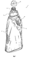
- a dispensing container according to the present invention is generally indicated by 1.
- the container 1 is meant to contain a fluid product for house-cleaning.
- the container 1 mainly comprises: a main bottle 2 for a fluid, apt to receive the fluid product to be dispensed; a metering receptacle 3, located above the main bottle 2 and apt to allow a metered outwardly dispensing of the product; and a duct 4, communicating the bottle 2 with the metering receptacle 3.
- the main bottle 2 has a base, or bottom, 21 and a sidewall 22, the latter shaped so as to have sides 23 and 24 having a sinuous contour.
- the duct 4 which therefore develops according to the same sinuous contour.
- the main bottle 2 has a cross section of elongated shape.
- a gripping seat 5 is obtained, just for allowing a user's gripping the container 1.
- the bottle 2 has an outlet port, denoted by 6, for the fluid product, located at the side 24 of the bottle 2 itself and near or adjacent to the bottom 21, substantially at the same level of the latter.
- the outlet port 6 has a substantially elongated shape, with a greater transverse dimension 61 thereof located substantially parallel to the bottom 21 of the main bottle 2.
- such an outlet port 6 is substantially oval or elliptical.
- the metering receptacle 3 has a capacity substantially lower with respect to the main bottle 2, and it is meant, as mentioned above, to meter the fluid product contained in the container 1.
- the metering receptacle 3 bears, at a sidewall 31 thereof, graduation marks 32 apt to allow an accurate metering.
- the metering receptacle 3 is located substantially longitudinally aligned to the main bottle 2, and it also has a cross section of elongated shape and tilted sides, the latter indicated by 33 and 34, respectively, corresponding to the sides 23 and 24 of the main bottle 2.
- the duct 4 also extends along the side 34 of the metering receptacle 3, partly following its contour.
- the metering receptacle 3 is connected to the main bottle 2 by a vertical channel 13 substantially centered with respect to the longitudinal axis of the container 1.
- This vertical channel 13 is used by the manufacturer solely to fill the container 1, and in particular the main bottle 2 thereof.
- the channel 13 is sealed by the same manufacturer with a cap, so as not to be subsequently re-openable by the end user.
- the metering receptacle 3 further comprises a top opening 8 for outwardly dispensing the fluid product.
- opening 8 of the metering receptacle 3 opens on a neck 9 of the container 1 having an external thread apt to allow the closure thereof by a cap 10, the latter being shown by way of example in Figure 1 .
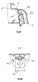
- the duct 4 has an internal lumen 12 connecting the outlet port 6 of the main bottle 2 to an inlet port 7 or 70 of the metering receptacle 3, so as to allow the transit of the fluid to be dispensed from the former to the latter.
- the container 1 is susceptible of various alternative embodiments.
- FIG. 4A and 5A A first embodiment is shown in Figures 4A and 5A .
- the metering receptacle 3 comprises a port for inletting the fluid product thereinto, in this case denoted by 7.
- This inlet port 7 is located at a top portion of the vessel 3, and in particular at the tilted side 34 thereof, hence substantially at the same side of the outlet port 6 of the bottle 2.
- the overall arrangement is such that, by virtue of the tilting of the side 34, the inlet port 7 substantially faces the bottom 21 of the container 1.
- the inlet port 7 has a substantially elongated shape and it is located with a greater transverse dimension 71 thereof substantially parallel to the bottom 21 of the main bottle 2.
- such inlet port 7 is substantially elliptical or oval.
- the metering receptacle 3 internally has a deviation member 11, extending thereinto from the internal face of the sidewall 31.
- the deviation member 11 is apt to deviate the flow of product crossing the port 7 toward the bottom of the metering receptacle 3, i.e. toward the bottom 21 of the container 1, so as to prevent a product outpouring from the top opening 8.
- the deviation member 11 is located at the inlet port 7, and in particular thereabove.
- the deviation member 11 is in form of a flap and it also implements a squirt guard member.
- the lumen 12 comprises an end portion 121 having a cross section increasing toward the inlet port 7 itself.
- such an end portion 121 has a substantially frustum-of-cone -shaped development.
- the cross section of the portion 121 matches that of the inlet port 7, hence having an analogous substantially elongated shape, and in particular elliptical or oval, and an analogous arrangement with a greater cross dimension substantially parallel to the bottom 21 of the container 1.
- the internal lumen 12 of the duct 4 has a portion having a cross section of shape and arrangement analogous to those of the outlet port 6 itself.
- a second embodiment of the container 1, and especially of the end portion of the duct 4 ending into the metering receptacle 3, will hereinafter be described with reference to Figures 4B and 5B and in connection to the sole aspects differentiating such second embodiment from the first one.
- the metering receptacle 3 comprises an inlet port, in this case indicated by 70, located also in this case at the tilted side 34 of the receptacle 3 itself.
- the overall arrangement is such that by virtue of the tilting of the side 34 the inlet port 70 substantially faces the bottom 21 of the container 1.
- the inlet port 70 has a substantially elongated shape and is located with a greater transverse dimension 710 thereof substantially parallel to the bottom 21 of the main bottle 2.
- this inlet port 70 is substantially half-ellipse- or half-moon-shaped.
- the lumen 12 comprises, at the inlet port 70 of the metering receptacle 3, an end portion, in this case indicated by 1210, having a substantially descending development tilted toward the bottom 21 of the container 1, therefore extending substantially bottomwise.
- the cross section of the portion 1210 matches that of the inlet port 70, hence having an analogous substantially half-ellipse or half-moon shape, and an analogous arrangement with a greater transverse dimension substantially parallel to the bottom 21 of the container 1.
- the end portion 1210 has a cross section increasing toward the inlet port 70.
- the end portion 1210 has, at a bottom wall 1211 thereof, a substantially frustum-of-cone -shaped development having an elliptical base, so as to implement the abovementioned half-ellipse or half-moon shape of the cross section.
- the wall of the side 34 arranged above the inlet port 70 has an appendix 1212 extending substantially at the top mouthpiece of the port 70 itself.
- This appendix 1212 has a substantially vertical development and serves as a flow deviation member, analogously to the flap 11 of the preceding embodiment.
- the appendix 1212 deviates the flow of product downwards, i.e. toward the bottom of the metering receptacle 3 (and therefore toward the bottom 21 of the container 1).
- the lumen 12 has a substantially circular cross section along the entire length of the duct 4, said section assuming an elongated section merely in the end parts at the outlet port 6 and inlet port 7, 70.
- the container 1, and in particular the main bottle 2 thereof, is made of a material having an elastic deformability such as to allow the container 2 to be deformed to cause the fluid product to inflow through the duct 4 and into the metering receptacle 3. Moreover, the container 1 may be piece-formed by a blow-molding method.
- the specific shape having an increasing cross section of the end portion 121 or 1210 of the lumen 12 fosters an even outletting of the product, preventing outpourings of the latter from the container 1 and reducing or eliminating squirting.
- the hereto-described specific shape and arrangement of the lumen 12, in particular in the second embodiment illustrated with reference to Figures 4B and 5B causes a fan-shaped inflow of the product into the metering receptacle 3.
- the presence of the deviation member 11 or 1212 prevents, under any circumstance, that the product, turbulently flowing out from the duct 4 into the metering receptacle 3, directly outpours from the container 1 through the top opening 8.
- this member 11 or 1212 works as a barrier for the fluid product, deviating the latter downwards and letting it flow toward the bottom of the metering receptacle.
- the user may dispense it in the desired dose, also with the aid of the gradation marks 32.
- the end portion of the duct internal lumen arranged near to the inlet port of the metering receptacle may have a substantially frustum-of-pyramid development instead of a frustum-of-cone one.
Landscapes
- Fluid Mechanics (AREA)
- General Physics & Mathematics (AREA)
- Physics & Mathematics (AREA)
- Details Of Rigid Or Semi-Rigid Containers (AREA)
- Containers And Packaging Bodies Having A Special Means To Remove Contents (AREA)
- Beans For Foods Or Fodder (AREA)
- Control And Other Processes For Unpacking Of Materials (AREA)
- Closures For Containers (AREA)
- Massaging Devices (AREA)
- Medicinal Preparation (AREA)
- Treatments For Attaching Organic Compounds To Fibrous Goods (AREA)
- Medicines That Contain Protein Lipid Enzymes And Other Medicines (AREA)
- Surgical Instruments (AREA)
- Investigating Or Analysing Biological Materials (AREA)
Abstract
Description
- The present invention relates to a dispensing container, and in particular to a container of the type comprising a main bottle receiving a fluid product to be dispensed and a metering receptacle connected to the main bottle by a duct, in which the main bottle is apt to be deformed to cause the inflow of the fluid product through the duct and into the metering receptacle.
- Several types of the hereto-introduced container are known. In particular,
EP 0 010 965 to Bettix Limited discloses a deformable container, in which a main bottle for a liquid and a metering receptacle are arranged side-by-side and are mutually connected by a duct having a sinuous course. By pressing onto the walls of the main bottle, the user makes the liquid inflow from such bottle into the duct, and from the latter into the metering receptacle. Then the liquid is dispensed outwardly through a top opening of the metering receptacle. -
US 4,640,441 discloses a container having a reservoir chamber and a dosage chamber connected by a duct. Duct opens into dosage chamber through two inlets located one above the other. The reservoir chamber can be squeezed to deliver the fluid contained therein into the dosage chamber through the duct and its inlets. The fluid is then delivered outside the container through a discharge conduit. One of the inlets is located at a top wall of the dosage chamber, has an irregular shape and is arranged so that the flow path enters the dosage chamber inclined downwardly. The present invention stems from the observation that the known-art container just described entails the drawback that the liquid coming from the main bottle is violently expressed into the metering receptacle and tends to directly outpour through the top opening of the latter. This is due to the fact that the main bottle has to be pressed vehemently in order to make the liquid inflow from the bottle itself into the metering receptacle, and from the fact that the cap usually closing the top opening of the metering receptacle has to be removed or at least loosened in order to allow the outlet of air required for liquid inlet. - Hence, the known-art containers described hereto can be cumbersome and less than practical to use. Moreover, they can cause an undesired waste of the product contained therein. Furthermore - and above all - such known-art containers cause a difficult metering of the product.
- Hence, the technical problem underlying the present invention is that of providing a dispensing container allowing to overcome the drawbacks mentioned above with reference to the known art.
- Such a problem is solved by a container according to claim 1.
- Preferred features of the present invention reside in the dependant claims thereof. The present invention provides some relevant advantages. The main advantage lies in the fact that the specific shape of the duct lumen near the inlet port of the fluid into the metering receptacle reduces the fluid outflow rate, fostering an even outflow of the fluid into the metering receptacle and thereby avoiding outpours outside of the container. This also prevents squirting from the container and facilitates the metering steps.
- Hence, the container of the invention is convenient and practical to use. Moreover, it avoids any waste of the fluid product contained therein.
- Other advantages, features and the operation steps of the present invention will be made apparent in the following detailed description of some embodiments thereof, given by way of examples and not for limitative purposes. It will be made reference to the figures of the annexed drawings, wherein:
-
Figure 1 shows a perspective view of an embodiment of the container according to the present invention; -
Figure 2 shows a front view of the container ofFigure 1 ; -
Figure 3 shows a side view of the container ofFigure 1 ; -
Figure 4A shows a sectional view of an enlarged detail of a first embodiment of the container ofFigure 2 , taken along a plane parallel to that of the latter Figure; -
Figure 5A shows a sectional view of an enlarged detail of the container ofFigure 4A , taken along line B-B of the latter Figure; -
Figure 4B shows a sectional view of an enlarged detail of a second embodiment of the container ofFigure 2 , taken along a plane parallel to that of the latter Figure; and -
Figure 5B shows a sectional view of an enlarged detail of the container ofFigure 4B , taken along line B-B of the latter Figure. - Referring initially to
Figure 1 , a dispensing container according to the present invention is generally indicated by 1. - In the present embodiment, the container 1 is meant to contain a fluid product for house-cleaning.
- The container 1 mainly comprises: a
main bottle 2 for a fluid, apt to receive the fluid product to be dispensed; ametering receptacle 3, located above themain bottle 2 and apt to allow a metered outwardly dispensing of the product; and a duct 4, communicating thebottle 2 with themetering receptacle 3. Each of such components will be described in greater detail in the following, with reference to two specific embodiments of the invention. - As best seen in
Figure 2 , themain bottle 2 has a base, or bottom, 21 and a sidewall 22, the latter shaped so as to havesides side 24 of thecontainer 2 there extends also the duct 4, which therefore develops according to the same sinuous contour. - In the present embodiment, the
main bottle 2 has a cross section of elongated shape. - Within the main bottle 2 a
gripping seat 5 is obtained, just for allowing a user's gripping the container 1. - The
bottle 2 has an outlet port, denoted by 6, for the fluid product, located at theside 24 of thebottle 2 itself and near or adjacent to thebottom 21, substantially at the same level of the latter. - As best seen in
Figure 3 , the outlet port 6 has a substantially elongated shape, with a greatertransverse dimension 61 thereof located substantially parallel to thebottom 21 of themain bottle 2. In the present embodiment such an outlet port 6 is substantially oval or elliptical. - Further referring to
Figure 2 , themetering receptacle 3 has a capacity substantially lower with respect to themain bottle 2, and it is meant, as mentioned above, to meter the fluid product contained in the container 1. For this purpose, themetering receptacle 3 bears, at asidewall 31 thereof, graduation marks 32 apt to allow an accurate metering. - The
metering receptacle 3 is located substantially longitudinally aligned to themain bottle 2, and it also has a cross section of elongated shape and tilted sides, the latter indicated by 33 and 34, respectively, corresponding to thesides main bottle 2. The duct 4 also extends along theside 34 of themetering receptacle 3, partly following its contour. - The
metering receptacle 3 is connected to themain bottle 2 by avertical channel 13 substantially centered with respect to the longitudinal axis of the container 1. Thisvertical channel 13 is used by the manufacturer solely to fill the container 1, and in particular themain bottle 2 thereof. Upon attaining the initial filling of thebottle 2, thechannel 13 is sealed by the same manufacturer with a cap, so as not to be subsequently re-openable by the end user. - The
metering receptacle 3 further comprises atop opening 8 for outwardly dispensing the fluid product. In particular, such opening 8 of themetering receptacle 3 opens on aneck 9 of the container 1 having an external thread apt to allow the closure thereof by acap 10, the latter being shown by way of example inFigure 1 . As it is shown, e.g., inFigures 4A and4B , the duct 4 has aninternal lumen 12 connecting the outlet port 6 of themain bottle 2 to aninlet port 7 or 70 of themetering receptacle 3, so as to allow the transit of the fluid to be dispensed from the former to the latter. - At the portion of the duct 4 ending into the
metering receptacle 3, the container 1 is susceptible of various alternative embodiments. - A first embodiment is shown in
Figures 4A and 5A . Referring to these latter figures, as already mentioned above themetering receptacle 3 comprises a port for inletting the fluid product thereinto, in this case denoted by 7. This inlet port 7 is located at a top portion of thevessel 3, and in particular at thetilted side 34 thereof, hence substantially at the same side of the outlet port 6 of thebottle 2. The overall arrangement is such that, by virtue of the tilting of theside 34, the inlet port 7 substantially faces thebottom 21 of the container 1. - As it is shown in greater detail in
Figure 5A , also the inlet port 7 has a substantially elongated shape and it is located with a greatertransverse dimension 71 thereof substantially parallel to thebottom 21 of themain bottle 2. In particular, in the present embodiment such inlet port 7 is substantially elliptical or oval. - As it is shown always in
Figures 4A and 5A , in the present embodiment themetering receptacle 3 internally has adeviation member 11, extending thereinto from the internal face of thesidewall 31. As it will be detailed later on, thedeviation member 11 is apt to deviate the flow of product crossing the port 7 toward the bottom of themetering receptacle 3, i.e. toward thebottom 21 of the container 1, so as to prevent a product outpouring from the top opening 8. - More precisely, the
deviation member 11 is located at the inlet port 7, and in particular thereabove. In the present embodiment, thedeviation member 11 is in form of a flap and it also implements a squirt guard member. - At the inlet port 7 of the
metering receptacle 3, thelumen 12 comprises anend portion 121 having a cross section increasing toward the inlet port 7 itself. - In the present embodiment, such an
end portion 121 has a substantially frustum-of-cone -shaped development. The cross section of theportion 121 matches that of the inlet port 7, hence having an analogous substantially elongated shape, and in particular elliptical or oval, and an analogous arrangement with a greater cross dimension substantially parallel to the bottom 21 of the container 1. - Of course, even near the outlet port 6 of the
bottle 2 theinternal lumen 12 of the duct 4 has a portion having a cross section of shape and arrangement analogous to those of the outlet port 6 itself. - A second embodiment of the container 1, and especially of the end portion of the duct 4 ending into the
metering receptacle 3, will hereinafter be described with reference toFigures 4B and 5B and in connection to the sole aspects differentiating such second embodiment from the first one. - In such second embodiment, the
metering receptacle 3 comprises an inlet port, in this case indicated by 70, located also in this case at the tiltedside 34 of thereceptacle 3 itself. Hence, in this case as well, the overall arrangement is such that by virtue of the tilting of theside 34 theinlet port 70 substantially faces the bottom 21 of the container 1. - As it is shown in greater detail in
Figure 5B , also theinlet port 70 has a substantially elongated shape and is located with a greatertransverse dimension 710 thereof substantially parallel to the bottom 21 of themain bottle 2. In particular, in the present embodiment thisinlet port 70 is substantially half-ellipse- or half-moon-shaped. - As it is shown always in
Figures 4B and 5B , thelumen 12 comprises, at theinlet port 70 of themetering receptacle 3, an end portion, in this case indicated by 1210, having a substantially descending development tilted toward the bottom 21 of the container 1, therefore extending substantially bottomwise. - The cross section of the
portion 1210 matches that of theinlet port 70, hence having an analogous substantially half-ellipse or half-moon shape, and an analogous arrangement with a greater transverse dimension substantially parallel to the bottom 21 of the container 1. - The
end portion 1210 has a cross section increasing toward theinlet port 70. In particular, in the present embodiment theend portion 1210 has, at abottom wall 1211 thereof, a substantially frustum-of-cone -shaped development having an elliptical base, so as to implement the abovementioned half-ellipse or half-moon shape of the cross section. - The wall of the
side 34 arranged above theinlet port 70 has anappendix 1212 extending substantially at the top mouthpiece of theport 70 itself. Thisappendix 1212 has a substantially vertical development and serves as a flow deviation member, analogously to theflap 11 of the preceding embodiment. In particular, theappendix 1212 deviates the flow of product downwards, i.e. toward the bottom of the metering receptacle 3 (and therefore toward the bottom 21 of the container 1). - Returning now to the general description of the container 1, in the present embodiment the
lumen 12 has a substantially circular cross section along the entire length of the duct 4, said section assuming an elongated section merely in the end parts at the outlet port 6 andinlet port 7, 70. - The container 1, and in particular the
main bottle 2 thereof, is made of a material having an elastic deformability such as to allow thecontainer 2 to be deformed to cause the fluid product to inflow through the duct 4 and into themetering receptacle 3. Moreover, the container 1 may be piece-formed by a blow-molding method. - The operation modes of the container 1 will be illustrated hereinafter with reference to the hereto-introduced figures.
- When a user wishes to dispense the fluid product contained in the container 1, he/she squeezes the sidewall 22 of the
main bottle 2. Such a squeezing reduces the internal volume of the latter and expresses the product through the duct 4 and therefrom into themetering receptacle 3. - It will be appreciated that, as mentioned above, the specific shape having an increasing cross section of the
end portion lumen 12 fosters an even outletting of the product, preventing outpourings of the latter from the container 1 and reducing or eliminating squirting. In particular, the hereto-described specific shape and arrangement of thelumen 12, in particular in the second embodiment illustrated with reference toFigures 4B and 5B , causes a fan-shaped inflow of the product into themetering receptacle 3. - Moreover, the presence of the
deviation member metering receptacle 3, directly outpours from the container 1 through thetop opening 8. In fact, thismember - In the second embodiment illustrated above, this latter advantage is obtained also by virtue of the descending course of the
end portion 1210 of thelumen 12. In fact, such a course, jointly to the fact that theinlet port 7, 70 substantially faces the bottom 21 of the container 1, allows the flow of product to have a substantially downwardly oriented direction of inlet into themetering receptacle 3. - Besides, these advantages are important since a user is hardly capable of accurately gauging the force required to make the product evenly inflow from the
bottle 2 into the metering receptacle 3 - also since such force should vary according to the amount of fluid remaining into thebottle 2 itself as well - entailing that often the fluid product receives a thrust markedly greater than the required one. Moreover, the elongated shape and the specific arrangement of the cross section of the outlet port 6 and of thelumen portion 12 near such port 6 allows the product to be dispensable down to the total emptying of thebottle 2, preventing unused product from remaining onto the bottom 21 of the container 1. - Upon transferring the fluid product from the
bottle 2 to themetering receptacle 3, the user may dispense it in the desired dose, also with the aid of the gradation marks 32. - It will be understood that the present invention is susceptible of several forms and embodiments alternative to the hereto-described ones, above all concerning the inlet of the metering receptacle and the duct portion adjacent thereto.
- For example, the end portion of the duct internal lumen arranged near to the inlet port of the metering receptacle may have a substantially frustum-of-pyramid development instead of a frustum-of-cone one.
- The present invention has been hereto described with reference to preferred embodiments thereof. It is understood that other embodiments might exist, all falling within the concept of the same invention, and all comprised within the protective scope of the claims hereinafter.
Claims (26)
- A dispensing container (1), comprising:- a main bottle (2), apt to receive the fluid product to be dispensed and having an outlet port (6) for the fluid product itself;- a metering receptacle (3), having a port (7; 70) for the inlet of the fluid product thereinto, which inlet port (7; 70) is located at a sidewall thereof, and an opening (8) for outwardly dispensing the fluid product; and- a duct (4), having an internal lumen (12) connecting said outlet port (6) of said main bottle (2) to said inlet port (7; 70) of said metering receptacle (3),wherein said main bottle (2) is of the type apt to be deformed for causing the inflow of the fluid product into said metering receptacle (3) through said duct (4),
characterized
in that said internal lumen (12) of said duct (4) comprises, at said inlet port (7; 70) of said metering receptacle (3), an end portion (121; 1210) having a cross section increasing toward said inlet port (7; 70),
and in that said end portion (121; 1210) of said internal lumen (12) and said inlet port (7; 70) of said metering receptacle (3) have a cross section of substantially elongated shape and are arranged so that a greater transverse dimension (71; 710) thereof be substantially parallel to the bottom (21) of the container itself. - The container (1) according to claim 1, wherein said end portion (121; 1210) of said internal lumen (12) has at least partly a substantially frustum-of-cone or frustum-of-pyramid -shaped development.
- The container (1) according to claim 1 or 2, wherein said end portion (121) of said internal lumen (12) and said inlet port (7) of said metering receptacle (3) have a cross section of substantially elliptical shape.
- The container (1) according to claim 1 or 2, wherein said end portion (121) of said internal lumen (12) and said inlet port (7) of said metering receptacle (3) have a cross section of substantially oval shape.
- The container (1) according to claim 1 or 2, wherein said end portion (1210) of said internal lumen (12) and said inlet port (70) of said metering receptacle (3) have a cross section of substantially half-ellipse or half-moon shape.
- The container (1) according to any one of the preceding claims, wherein said end portion (121) of said internal lumen (12) extends substantially parallel to the bottom (21) of the container itself.
- The container (1) according to any one of the claims 1 to 5, wherein said end portion (1210) of said internal lumen (120) has a descending development substantially tilted toward the bottom (21) of the container itself.
- The container (1) according to any one of the preceding claims, wherein said duct (4) extends along a side (24, 34) of the container itself.
- The container (1) according to any one of the preceding claims, wherein said metering receptacle (3) is located above said main bottle (2).
- The container (1) according to any one of the preceding claims, wherein said metering receptacle (3) is located substantially longitudinally aligned with said main bottle (2).
- The container (1) according to any one of the preceding claims, wherein said inlet port (7; 70) of said metering receptacle (3) is located at a wall (34) of said metering receptacle (3) having a tilt such that said inlet port (7; 70) faces the bottom (21) of the container itself.
- The container (1) according to any one of the preceding claims, wherein said inlet port (7; 70) of said metering receptacle (3) is located at a top portion thereof.
- The container (1) according to any one of the preceding claims, wherein said metering receptacle (3) comprises a deviation member (11; 1212) apt to deviate the flow of product coming from said duct (4) toward the bottom of said metering receptacle (3).
- The container (1) according to the preceding claim, wherein said deviation member (11; 1212) is located at said inlet port (7; 70) of said metering receptacle (3).
- The container (1) according to the preceding claim, wherein said deviation member (11; 1212) is located above said inlet port (7; 70) of said metering receptacle (3).
- The container (1) according to any one of the claims 13 to 15, wherein said deviation member (11; 1212) is apt to serve as squirt guard.
- The container (1) according to any one of the claims 13 to 16, wherein said deviation member (11; 1212) comprises a flap extending internally to said metering receptacle (3).
- The container (1) according to any one of the claims 13 to 17, wherein said deviation member comprises a member (1212) extending at the top mouthpiece of said inlet port (70).
- The container (1) according to the preceding claim, wherein said member (1212) extending at the top mouthpiece of said inlet port (70) is obtained as an appendix of a wall of said metering receptacle (3).
- The container (1) according to any one of the preceding claims, wherein said opening (8) of said metering receptacle (3) is located at a top wall of the metering receptacle (3) itself.
- The container (1) according to any one of the preceding claims, wherein said outlet port (6) of said main bottle (2) is located at the bottom (21) of the main bottle itself.
- The container (1) according to any one of the preceding claims, wherein said outlet port (6) of said main bottle (2) has a substantially elongated shape.
- The container (1) according to the preceding claim, wherein said outlet port (6) of said main bottle (2) is located with a greater transverse dimension (61) thereof substantially parallel to the bottom (21) of the main bottle (2) itself.
- The container (1) according to claim 22 or 23, wherein said outlet port (6) is substantially elliptic.
- The container (1) according to claim 22 or 23, wherein said outlet port (6) is substantially oval.
- The container (1) according to any one of the preceding claims, having a gripping seat (5) of the container itself obtained in said main bottle (2).
Priority Applications (2)
| Application Number | Priority Date | Filing Date | Title |
|---|---|---|---|
| SI200332066T SI1636552T1 (en) | 2003-06-24 | 2003-06-24 | Dispensing container |
| CY20111101042T CY1113219T1 (en) | 2003-06-24 | 2011-10-31 | DISTRIBUTION CONTAINER |
Applications Claiming Priority (1)
| Application Number | Priority Date | Filing Date | Title |
|---|---|---|---|
| PCT/IT2003/000392 WO2004113850A1 (en) | 2003-06-24 | 2003-06-24 | Dispensing container |
Publications (3)
| Publication Number | Publication Date |
|---|---|
| EP1636552A1 EP1636552A1 (en) | 2006-03-22 |
| EP1636552B1 true EP1636552B1 (en) | 2011-08-03 |
| EP1636552B8 EP1636552B8 (en) | 2012-03-07 |
Family
ID=33524022
Family Applications (1)
| Application Number | Title | Priority Date | Filing Date |
|---|---|---|---|
| EP03741066A Expired - Lifetime EP1636552B8 (en) | 2003-06-24 | 2003-06-24 | Dispensing container |
Country Status (13)
| Country | Link |
|---|---|
| EP (1) | EP1636552B8 (en) |
| AT (1) | ATE519097T1 (en) |
| AU (1) | AU2003304227A1 (en) |
| CY (1) | CY1113219T1 (en) |
| DK (1) | DK1636552T3 (en) |
| ES (1) | ES2370879T3 (en) |
| HR (1) | HRP20060032B1 (en) |
| IL (1) | IL173285A (en) |
| IS (1) | IS2836B (en) |
| PL (1) | PL214693B1 (en) |
| PT (1) | PT1636552E (en) |
| SI (1) | SI1636552T1 (en) |
| WO (1) | WO2004113850A1 (en) |
Family Cites Families (6)
| Publication number | Priority date | Publication date | Assignee | Title |
|---|---|---|---|---|
| US2714975A (en) * | 1950-10-05 | 1955-08-09 | Greene Norman | Combination closure and liquid dispenser for bottles, etc. |
| CA1178252A (en) * | 1981-03-02 | 1984-11-20 | Anthony D. Jackman | Dispensing container |
| GB8412297D0 (en) * | 1984-05-14 | 1984-06-20 | Unilever Plc | Liquid dispensing container |
| US4646948A (en) * | 1985-10-03 | 1987-03-03 | Container Mfg. Inc. | Measuring container with modified pour-spout and method and apparatus for filling the same |
| DE8625869U1 (en) * | 1986-09-27 | 1987-04-23 | C.F. Spiess & Sohn Kunststoffwerk GmbH & Co, 6719 Kleinkarlbach | Dosing container for liquid made of elastic plastic |
| US6290102B1 (en) * | 2000-03-31 | 2001-09-18 | Robert Michael Jennings | Liquid measuring and dispensing container |
-
2003
- 2003-06-24 DK DK03741066.9T patent/DK1636552T3/en active
- 2003-06-24 PL PL380433A patent/PL214693B1/en unknown
- 2003-06-24 EP EP03741066A patent/EP1636552B8/en not_active Expired - Lifetime
- 2003-06-24 AU AU2003304227A patent/AU2003304227A1/en not_active Abandoned
- 2003-06-24 PT PT03741066T patent/PT1636552E/en unknown
- 2003-06-24 WO PCT/IT2003/000392 patent/WO2004113850A1/en not_active Ceased
- 2003-06-24 SI SI200332066T patent/SI1636552T1/en unknown
- 2003-06-24 ES ES03741066T patent/ES2370879T3/en not_active Expired - Lifetime
- 2003-06-24 HR HRP20060032AA patent/HRP20060032B1/en not_active IP Right Cessation
- 2003-06-24 AT AT03741066T patent/ATE519097T1/en active
-
2006
- 2006-01-22 IL IL173285A patent/IL173285A/en not_active IP Right Cessation
- 2006-01-23 IS IS8253A patent/IS2836B/en unknown
-
2011
- 2011-10-31 CY CY20111101042T patent/CY1113219T1/en unknown
Also Published As
| Publication number | Publication date |
|---|---|
| HRP20060032A2 (en) | 2008-11-30 |
| PT1636552E (en) | 2011-11-15 |
| AU2003304227A8 (en) | 2012-01-19 |
| IL173285A (en) | 2010-12-30 |
| ES2370879T3 (en) | 2011-12-23 |
| DK1636552T3 (en) | 2011-11-21 |
| PL380433A1 (en) | 2007-01-22 |
| HRP20060032B1 (en) | 2012-06-30 |
| AU2003304227A1 (en) | 2005-01-04 |
| SI1636552T1 (en) | 2012-01-31 |
| IL173285A0 (en) | 2006-06-11 |
| PL214693B1 (en) | 2013-09-30 |
| IS2836B (en) | 2013-05-15 |
| ATE519097T1 (en) | 2011-08-15 |
| WO2004113850A8 (en) | 2005-03-10 |
| CY1113219T1 (en) | 2016-04-13 |
| WO2004113850A1 (en) | 2004-12-29 |
| ES2370879T8 (en) | 2012-01-10 |
| EP1636552A1 (en) | 2006-03-22 |
| IS8253A (en) | 2006-01-23 |
| EP1636552B8 (en) | 2012-03-07 |
Similar Documents
| Publication | Publication Date | Title |
|---|---|---|
| US11415448B2 (en) | Dosing timer and dispensers using the same | |
| US5054660A (en) | Self-dosing measuring chamber and container | |
| EP2444782B1 (en) | Liquid dosing apparatus | |
| EP0117423B1 (en) | Dosage dispensing unit | |
| US4582230A (en) | Metering device | |
| US4438869A (en) | Dosing device with ball valve and operating method | |
| US4394943A (en) | Tilting trap chamber | |
| US20090159620A1 (en) | Dispensing device for dispensing a liquid product | |
| WO1991000833A1 (en) | Metering | |
| US20210231480A1 (en) | Container | |
| ITMI940622A1 (en) | DISPENSER FOR DOSING TWO LIQUID OR PASTE PRODUCTS IN THE DESIRED PROPORTION | |
| EP1636552B1 (en) | Dispensing container | |
| US7942292B2 (en) | Pre-measured material dispenser with pivoting reservoir | |
| EP1000325A1 (en) | Assembly comprising a flexible container having a dosing device and dosing device of such assembly | |
| WO2011110999A1 (en) | Dispensing device | |
| JP5538193B2 (en) | Dispensing container | |
| EP0701108A1 (en) | A metering device | |
| JP6903480B2 (en) | Noter | |
| WO1993003338A1 (en) | Viscous liquid dispenser with integral measuring device | |
| JPH0118524Y2 (en) | ||
| EP0696541A1 (en) | Container comprising a metering device | |
| JPH0439178Y2 (en) | ||
| JP2025007212A (en) | Fixed quantity discharge container | |
| US20150321797A1 (en) | Multi-chamber container | |
| WO2008018093A1 (en) | Dosing cap for granulated substances |
Legal Events
| Date | Code | Title | Description |
|---|---|---|---|
| PUAI | Public reference made under article 153(3) epc to a published international application that has entered the european phase |
Free format text: ORIGINAL CODE: 0009012 |
|
| 17P | Request for examination filed |
Effective date: 20060111 |
|
| AK | Designated contracting states |
Kind code of ref document: A1 Designated state(s): AT BE BG CH CY CZ DE DK EE ES FI FR GB GR HU IE IT LI LU MC NL PT RO SE SI SK TR |
|
| AX | Request for extension of the european patent |
Extension state: AL LT LV MK |
|
| RAP1 | Party data changed (applicant data changed or rights of an application transferred) |
Owner name: SUTTER INDUSTRIES S.P.A. |
|
| GRAP | Despatch of communication of intention to grant a patent |
Free format text: ORIGINAL CODE: EPIDOSNIGR1 |
|
| GRAS | Grant fee paid |
Free format text: ORIGINAL CODE: EPIDOSNIGR3 |
|
| GRAA | (expected) grant |
Free format text: ORIGINAL CODE: 0009210 |
|
| AK | Designated contracting states |
Kind code of ref document: B1 Designated state(s): AT BE BG CH CY CZ DE DK EE ES FI FR GB GR HU IE IT LI LU MC NL PT RO SE SI SK TR |
|
| AX | Request for extension of the european patent |
Extension state: AL LT LV MK |
|
| REG | Reference to a national code |
Ref country code: GB Ref legal event code: FG4D |
|
| REG | Reference to a national code |
Ref country code: CH Ref legal event code: EP |
|
| REG | Reference to a national code |
Ref country code: IE Ref legal event code: FG4D |
|
| REG | Reference to a national code |
Ref country code: DE Ref legal event code: R096 Ref document number: 60337914 Country of ref document: DE Effective date: 20110929 |
|
| REG | Reference to a national code |
Ref country code: RO Ref legal event code: EPE |
|
| REG | Reference to a national code |
Ref country code: SE Ref legal event code: TRGR |
|
| REG | Reference to a national code |
Ref country code: NL Ref legal event code: T3 |
|
| REG | Reference to a national code |
Ref country code: PT Ref legal event code: SC4A Free format text: AVAILABILITY OF NATIONAL TRANSLATION Effective date: 20111028 Ref country code: CH Ref legal event code: PCOW Free format text: SUTTER INDUSTRIES S.P.A.;LOCALITA LEIGOZZE 1;15060 BORGHETTO BORBERA (AL) (IT) |
|
| REG | Reference to a national code |
Ref country code: DK Ref legal event code: T3 |
|
| RAP2 | Party data changed (patent owner data changed or rights of a patent transferred) |
Owner name: SUTTER INDUSTRIES S.P.A. |
|
| REG | Reference to a national code |
Ref country code: CH Ref legal event code: NV Representative=s name: PATENTANWAELTE SCHAAD, BALASS, MENZL & PARTNER AG |
|
| REG | Reference to a national code |
Ref country code: ES Ref legal event code: FG2A Ref document number: 2370879 Country of ref document: ES Kind code of ref document: T3 Effective date: 20111223 |
|
| REG | Reference to a national code |
Ref country code: DE Ref legal event code: R081 Ref document number: 60337914 Country of ref document: DE Owner name: SUTTER INDUSTRIES S.P.A., IT Free format text: FORMER OWNER: SUTTER INDUSTRIES S.P.A., BORGHETTO BORBERO (AL), IT Effective date: 20111109 Ref country code: DE Ref legal event code: R081 Ref document number: 60337914 Country of ref document: DE Owner name: SUTTER INDUSTRIES S.P.A., IT Free format text: FORMER OWNER: SUTTERN FINANZIARIA S.P.A., BORGHETTO BORBERA, IT Effective date: 20110811 |
|
| REG | Reference to a national code |
Ref country code: GR Ref legal event code: EP Ref document number: 20110402550 Country of ref document: GR Effective date: 20111117 |
|
| REG | Reference to a national code |
Ref country code: EE Ref legal event code: FG4A Ref document number: E006203 Country of ref document: EE Effective date: 20111028 |
|
| REG | Reference to a national code |
Ref country code: SK Ref legal event code: T3 Ref document number: E 10674 Country of ref document: SK |
|
| REG | Reference to a national code |
Ref country code: HU Ref legal event code: AG4A Ref document number: E012728 Country of ref document: HU |
|
| PLBE | No opposition filed within time limit |
Free format text: ORIGINAL CODE: 0009261 |
|
| STAA | Information on the status of an ep patent application or granted ep patent |
Free format text: STATUS: NO OPPOSITION FILED WITHIN TIME LIMIT |
|
| 26N | No opposition filed |
Effective date: 20120504 |
|
| REG | Reference to a national code |
Ref country code: DE Ref legal event code: R097 Ref document number: 60337914 Country of ref document: DE Effective date: 20120504 |
|
| REG | Reference to a national code |
Ref country code: DE Ref legal event code: R082 Ref document number: 60337914 Country of ref document: DE Representative=s name: SCHUMACHER & WILLSAU PATENTANWALTSGESELLSCHAFT, DE |
|
| REG | Reference to a national code |
Ref country code: FR Ref legal event code: PLFP Year of fee payment: 13 |
|
| PGFP | Annual fee paid to national office [announced via postgrant information from national office to epo] |
Ref country code: MC Payment date: 20150612 Year of fee payment: 13 Ref country code: FI Payment date: 20150611 Year of fee payment: 13 Ref country code: SE Payment date: 20150618 Year of fee payment: 13 Ref country code: DK Payment date: 20150618 Year of fee payment: 13 Ref country code: DE Payment date: 20150619 Year of fee payment: 13 Ref country code: CZ Payment date: 20150623 Year of fee payment: 13 Ref country code: BG Payment date: 20150611 Year of fee payment: 13 Ref country code: SI Payment date: 20150526 Year of fee payment: 13 Ref country code: EE Payment date: 20150611 Year of fee payment: 13 Ref country code: ES Payment date: 20150626 Year of fee payment: 13 Ref country code: CH Payment date: 20150618 Year of fee payment: 13 Ref country code: LU Payment date: 20150624 Year of fee payment: 13 Ref country code: TR Payment date: 20150526 Year of fee payment: 13 Ref country code: PT Payment date: 20150618 Year of fee payment: 13 Ref country code: SK Payment date: 20150623 Year of fee payment: 13 Ref country code: RO Payment date: 20150528 Year of fee payment: 13 Ref country code: GB Payment date: 20150618 Year of fee payment: 13 |
|
| PGFP | Annual fee paid to national office [announced via postgrant information from national office to epo] |
Ref country code: FR Payment date: 20150619 Year of fee payment: 13 Ref country code: BE Payment date: 20150618 Year of fee payment: 13 Ref country code: HU Payment date: 20150618 Year of fee payment: 13 Ref country code: NL Payment date: 20150618 Year of fee payment: 13 Ref country code: AT Payment date: 20150619 Year of fee payment: 13 Ref country code: GR Payment date: 20150611 Year of fee payment: 13 Ref country code: IE Payment date: 20150619 Year of fee payment: 13 |
|
| PGFP | Annual fee paid to national office [announced via postgrant information from national office to epo] |
Ref country code: CY Payment date: 20150610 Year of fee payment: 13 |
|
| PG25 | Lapsed in a contracting state [announced via postgrant information from national office to epo] |
Ref country code: BE Free format text: LAPSE BECAUSE OF NON-PAYMENT OF DUE FEES Effective date: 20160630 |
|
| REG | Reference to a national code |
Ref country code: DE Ref legal event code: R119 Ref document number: 60337914 Country of ref document: DE |
|
| REG | Reference to a national code |
Ref country code: LT Ref legal event code: MM9D Effective date: 20160624 |
|
| REG | Reference to a national code |
Ref country code: EE Ref legal event code: MM4A Ref document number: E006203 Country of ref document: EE Effective date: 20160630 |
|
| REG | Reference to a national code |
Ref country code: DK Ref legal event code: EBP Effective date: 20160630 |
|
| PG25 | Lapsed in a contracting state [announced via postgrant information from national office to epo] |
Ref country code: CZ Free format text: LAPSE BECAUSE OF NON-PAYMENT OF DUE FEES Effective date: 20160624 Ref country code: CY Free format text: LAPSE BECAUSE OF NON-PAYMENT OF DUE FEES Effective date: 20160624 Ref country code: FI Free format text: LAPSE BECAUSE OF NON-PAYMENT OF DUE FEES Effective date: 20160624 Ref country code: MC Free format text: LAPSE BECAUSE OF NON-PAYMENT OF DUE FEES Effective date: 20160630 Ref country code: RO Free format text: LAPSE BECAUSE OF NON-PAYMENT OF DUE FEES Effective date: 20160624 |
|
| REG | Reference to a national code |
Ref country code: SE Ref legal event code: EUG Ref country code: CH Ref legal event code: PL |
|
| REG | Reference to a national code |
Ref country code: NL Ref legal event code: MM Effective date: 20160701 |
|
| REG | Reference to a national code |
Ref country code: AT Ref legal event code: MM01 Ref document number: 519097 Country of ref document: AT Kind code of ref document: T Effective date: 20160624 |
|
| PG25 | Lapsed in a contracting state [announced via postgrant information from national office to epo] |
Ref country code: SE Free format text: LAPSE BECAUSE OF NON-PAYMENT OF DUE FEES Effective date: 20160625 Ref country code: PT Free format text: LAPSE BECAUSE OF NON-PAYMENT OF DUE FEES Effective date: 20161227 |
|
| PGFP | Annual fee paid to national office [announced via postgrant information from national office to epo] |
Ref country code: IT Payment date: 20161114 Year of fee payment: 14 |
|
| GBPC | Gb: european patent ceased through non-payment of renewal fee |
Effective date: 20160624 |
|
| REG | Reference to a national code |
Ref country code: SK Ref legal event code: MM4A Ref document number: E 10674 Country of ref document: SK Effective date: 20160624 |
|
| REG | Reference to a national code |
Ref country code: GR Ref legal event code: ML Ref document number: 20110402550 Country of ref document: GR Effective date: 20170109 |
|
| REG | Reference to a national code |
Ref country code: IE Ref legal event code: MM4A |
|
| REG | Reference to a national code |
Ref country code: SI Ref legal event code: KO00 Effective date: 20170228 Ref country code: FR Ref legal event code: ST Effective date: 20170228 |
|
| PG25 | Lapsed in a contracting state [announced via postgrant information from national office to epo] |
Ref country code: FR Free format text: LAPSE BECAUSE OF NON-PAYMENT OF DUE FEES Effective date: 20160630 Ref country code: GR Free format text: LAPSE BECAUSE OF NON-PAYMENT OF DUE FEES Effective date: 20170109 Ref country code: CH Free format text: LAPSE BECAUSE OF NON-PAYMENT OF DUE FEES Effective date: 20160630 Ref country code: DE Free format text: LAPSE BECAUSE OF NON-PAYMENT OF DUE FEES Effective date: 20170103 Ref country code: EE Free format text: LAPSE BECAUSE OF NON-PAYMENT OF DUE FEES Effective date: 20160630 Ref country code: LI Free format text: LAPSE BECAUSE OF NON-PAYMENT OF DUE FEES Effective date: 20160630 Ref country code: HU Free format text: LAPSE BECAUSE OF NON-PAYMENT OF DUE FEES Effective date: 20160625 |
|
| PG25 | Lapsed in a contracting state [announced via postgrant information from national office to epo] |
Ref country code: AT Free format text: LAPSE BECAUSE OF NON-PAYMENT OF DUE FEES Effective date: 20160624 Ref country code: IE Free format text: LAPSE BECAUSE OF NON-PAYMENT OF DUE FEES Effective date: 20160624 Ref country code: NL Free format text: LAPSE BECAUSE OF NON-PAYMENT OF DUE FEES Effective date: 20160701 Ref country code: BG Free format text: LAPSE BECAUSE OF NON-PAYMENT OF DUE FEES Effective date: 20170131 Ref country code: SI Free format text: LAPSE BECAUSE OF NON-PAYMENT OF DUE FEES Effective date: 20160625 Ref country code: SK Free format text: LAPSE BECAUSE OF NON-PAYMENT OF DUE FEES Effective date: 20160624 Ref country code: GB Free format text: LAPSE BECAUSE OF NON-PAYMENT OF DUE FEES Effective date: 20160624 |
|
| PG25 | Lapsed in a contracting state [announced via postgrant information from national office to epo] |
Ref country code: DK Free format text: LAPSE BECAUSE OF NON-PAYMENT OF DUE FEES Effective date: 20160630 |
|
| PG25 | Lapsed in a contracting state [announced via postgrant information from national office to epo] |
Ref country code: IT Free format text: LAPSE BECAUSE OF NON-PAYMENT OF DUE FEES Effective date: 20170624 Ref country code: ES Free format text: LAPSE BECAUSE OF NON-PAYMENT OF DUE FEES Effective date: 20160625 |
|
| REG | Reference to a national code |
Ref country code: ES Ref legal event code: FD2A Effective date: 20180626 |
|
| PG25 | Lapsed in a contracting state [announced via postgrant information from national office to epo] |
Ref country code: LU Free format text: LAPSE BECAUSE OF NON-PAYMENT OF DUE FEES Effective date: 20160624 |
|
| PG25 | Lapsed in a contracting state [announced via postgrant information from national office to epo] |
Ref country code: TR Free format text: LAPSE BECAUSE OF NON-PAYMENT OF DUE FEES Effective date: 20160624 |