EP1635699B1 - Integriertes testelement zur einmaligen aufnahme und analyse einer zu untersuchenden probe - Google Patents
Integriertes testelement zur einmaligen aufnahme und analyse einer zu untersuchenden probe Download PDFInfo
- Publication number
- EP1635699B1 EP1635699B1 EP04739508A EP04739508A EP1635699B1 EP 1635699 B1 EP1635699 B1 EP 1635699B1 EP 04739508 A EP04739508 A EP 04739508A EP 04739508 A EP04739508 A EP 04739508A EP 1635699 B1 EP1635699 B1 EP 1635699B1
- Authority
- EP
- European Patent Office
- Prior art keywords
- light
- test field
- lancet
- conducting element
- sample
- Prior art date
- Legal status (The legal status is an assumption and is not a legal conclusion. Google has not performed a legal analysis and makes no representation as to the accuracy of the status listed.)
- Expired - Lifetime
Links
- 238000012360 testing method Methods 0.000 title claims description 179
- 210000004369 blood Anatomy 0.000 claims description 29
- 239000008280 blood Substances 0.000 claims description 29
- 238000000034 method Methods 0.000 claims description 21
- 239000003153 chemical reaction reagent Substances 0.000 claims description 18
- 230000008569 process Effects 0.000 claims description 18
- 239000012491 analyte Substances 0.000 claims description 14
- 230000008859 change Effects 0.000 claims description 11
- WQZGKKKJIJFFOK-GASJEMHNSA-N Glucose Natural products OC[C@H]1OC(O)[C@H](O)[C@@H](O)[C@@H]1O WQZGKKKJIJFFOK-GASJEMHNSA-N 0.000 claims description 3
- 239000008103 glucose Substances 0.000 claims description 3
- 239000000835 fiber Substances 0.000 claims 1
- 238000004458 analytical method Methods 0.000 description 74
- 239000012510 hollow fiber Substances 0.000 description 27
- 238000005259 measurement Methods 0.000 description 15
- 208000027418 Wounds and injury Diseases 0.000 description 14
- 230000003287 optical effect Effects 0.000 description 13
- 230000008878 coupling Effects 0.000 description 11
- 238000010168 coupling process Methods 0.000 description 11
- 238000005859 coupling reaction Methods 0.000 description 11
- 238000011156 evaluation Methods 0.000 description 10
- 230000010354 integration Effects 0.000 description 5
- 238000004159 blood analysis Methods 0.000 description 4
- 230000006870 function Effects 0.000 description 4
- 239000013307 optical fiber Substances 0.000 description 4
- 230000005855 radiation Effects 0.000 description 4
- 230000004888 barrier function Effects 0.000 description 3
- 230000000694 effects Effects 0.000 description 3
- 239000000463 material Substances 0.000 description 3
- 238000012544 monitoring process Methods 0.000 description 3
- 230000005540 biological transmission Effects 0.000 description 2
- 230000000295 complement effect Effects 0.000 description 2
- 238000002474 experimental method Methods 0.000 description 2
- 230000036512 infertility Effects 0.000 description 2
- 230000035515 penetration Effects 0.000 description 2
- 238000005375 photometry Methods 0.000 description 2
- 238000000926 separation method Methods 0.000 description 2
- 238000012546 transfer Methods 0.000 description 2
- 238000012351 Integrated analysis Methods 0.000 description 1
- 238000010521 absorption reaction Methods 0.000 description 1
- 238000006243 chemical reaction Methods 0.000 description 1
- 239000011248 coating agent Substances 0.000 description 1
- 238000000576 coating method Methods 0.000 description 1
- 238000011109 contamination Methods 0.000 description 1
- 230000006378 damage Effects 0.000 description 1
- 230000001419 dependent effect Effects 0.000 description 1
- 229920001971 elastomer Polymers 0.000 description 1
- 239000000806 elastomer Substances 0.000 description 1
- 210000003743 erythrocyte Anatomy 0.000 description 1
- 230000005284 excitation Effects 0.000 description 1
- 238000001727 in vivo Methods 0.000 description 1
- 208000014674 injury Diseases 0.000 description 1
- 230000002452 interceptive effect Effects 0.000 description 1
- 230000001678 irradiating effect Effects 0.000 description 1
- 230000000670 limiting effect Effects 0.000 description 1
- 239000007788 liquid Substances 0.000 description 1
- 230000007246 mechanism Effects 0.000 description 1
- 230000008058 pain sensation Effects 0.000 description 1
- 230000000737 periodic effect Effects 0.000 description 1
- 238000002360 preparation method Methods 0.000 description 1
- 230000001681 protective effect Effects 0.000 description 1
- 230000001012 protector Effects 0.000 description 1
- 230000035484 reaction time Effects 0.000 description 1
- 230000002829 reductive effect Effects 0.000 description 1
- 230000004044 response Effects 0.000 description 1
- 230000000284 resting effect Effects 0.000 description 1
- 230000002441 reversible effect Effects 0.000 description 1
- 238000007788 roughening Methods 0.000 description 1
- 238000005070 sampling Methods 0.000 description 1
- 239000000126 substance Substances 0.000 description 1
- 239000002699 waste material Substances 0.000 description 1
- 238000009736 wetting Methods 0.000 description 1
Images


Classifications
-
- A—HUMAN NECESSITIES
- A61—MEDICAL OR VETERINARY SCIENCE; HYGIENE
- A61B—DIAGNOSIS; SURGERY; IDENTIFICATION
- A61B5/00—Measuring for diagnostic purposes; Identification of persons
- A61B5/145—Measuring characteristics of blood in vivo, e.g. gas concentration or pH-value ; Measuring characteristics of body fluids or tissues, e.g. interstitial fluid or cerebral tissue
- A61B5/1455—Measuring characteristics of blood in vivo, e.g. gas concentration or pH-value ; Measuring characteristics of body fluids or tissues, e.g. interstitial fluid or cerebral tissue using optical sensors, e.g. spectral photometrical oximeters
- A61B5/1459—Measuring characteristics of blood in vivo, e.g. gas concentration or pH-value ; Measuring characteristics of body fluids or tissues, e.g. interstitial fluid or cerebral tissue using optical sensors, e.g. spectral photometrical oximeters invasive, e.g. introduced into the body by a catheter
-
- A—HUMAN NECESSITIES
- A61—MEDICAL OR VETERINARY SCIENCE; HYGIENE
- A61B—DIAGNOSIS; SURGERY; IDENTIFICATION
- A61B5/00—Measuring for diagnostic purposes; Identification of persons
- A61B5/145—Measuring characteristics of blood in vivo, e.g. gas concentration or pH-value ; Measuring characteristics of body fluids or tissues, e.g. interstitial fluid or cerebral tissue
- A61B5/14532—Measuring characteristics of blood in vivo, e.g. gas concentration or pH-value ; Measuring characteristics of body fluids or tissues, e.g. interstitial fluid or cerebral tissue for measuring glucose, e.g. by tissue impedance measurement
-
- A—HUMAN NECESSITIES
- A61—MEDICAL OR VETERINARY SCIENCE; HYGIENE
- A61B—DIAGNOSIS; SURGERY; IDENTIFICATION
- A61B5/00—Measuring for diagnostic purposes; Identification of persons
- A61B5/15—Devices for taking samples of blood
- A61B5/150007—Details
- A61B5/150015—Source of blood
- A61B5/150022—Source of blood for capillary blood or interstitial fluid
-
- A—HUMAN NECESSITIES
- A61—MEDICAL OR VETERINARY SCIENCE; HYGIENE
- A61B—DIAGNOSIS; SURGERY; IDENTIFICATION
- A61B5/00—Measuring for diagnostic purposes; Identification of persons
- A61B5/15—Devices for taking samples of blood
- A61B5/150007—Details
- A61B5/150358—Strips for collecting blood, e.g. absorbent
-
- A—HUMAN NECESSITIES
- A61—MEDICAL OR VETERINARY SCIENCE; HYGIENE
- A61B—DIAGNOSIS; SURGERY; IDENTIFICATION
- A61B5/00—Measuring for diagnostic purposes; Identification of persons
- A61B5/15—Devices for taking samples of blood
- A61B5/150007—Details
- A61B5/150374—Details of piercing elements or protective means for preventing accidental injuries by such piercing elements
- A61B5/150381—Design of piercing elements
- A61B5/150389—Hollow piercing elements, e.g. canulas, needles, for piercing the skin
-
- A—HUMAN NECESSITIES
- A61—MEDICAL OR VETERINARY SCIENCE; HYGIENE
- A61B—DIAGNOSIS; SURGERY; IDENTIFICATION
- A61B5/00—Measuring for diagnostic purposes; Identification of persons
- A61B5/15—Devices for taking samples of blood
- A61B5/150007—Details
- A61B5/150374—Details of piercing elements or protective means for preventing accidental injuries by such piercing elements
- A61B5/150381—Design of piercing elements
- A61B5/150503—Single-ended needles
-
- A—HUMAN NECESSITIES
- A61—MEDICAL OR VETERINARY SCIENCE; HYGIENE
- A61B—DIAGNOSIS; SURGERY; IDENTIFICATION
- A61B5/00—Measuring for diagnostic purposes; Identification of persons
- A61B5/15—Devices for taking samples of blood
- A61B5/150007—Details
- A61B5/150374—Details of piercing elements or protective means for preventing accidental injuries by such piercing elements
- A61B5/150534—Design of protective means for piercing elements for preventing accidental needle sticks, e.g. shields, caps, protectors, axially extensible sleeves, pivotable protective sleeves
- A61B5/150572—Pierceable protectors, e.g. shields, caps, sleeves or films, e.g. for hygienic purposes
-
- A—HUMAN NECESSITIES
- A61—MEDICAL OR VETERINARY SCIENCE; HYGIENE
- A61B—DIAGNOSIS; SURGERY; IDENTIFICATION
- A61B5/00—Measuring for diagnostic purposes; Identification of persons
- A61B5/15—Devices for taking samples of blood
- A61B5/150007—Details
- A61B5/150801—Means for facilitating use, e.g. by people with impaired vision; means for indicating when used correctly or incorrectly; means for alarming
- A61B5/150824—Means for facilitating use, e.g. by people with impaired vision; means for indicating when used correctly or incorrectly; means for alarming by visual feedback
-
- A—HUMAN NECESSITIES
- A61—MEDICAL OR VETERINARY SCIENCE; HYGIENE
- A61B—DIAGNOSIS; SURGERY; IDENTIFICATION
- A61B5/00—Measuring for diagnostic purposes; Identification of persons
- A61B5/15—Devices for taking samples of blood
- A61B5/157—Devices characterised by integrated means for measuring characteristics of blood
-
- A—HUMAN NECESSITIES
- A61—MEDICAL OR VETERINARY SCIENCE; HYGIENE
- A61B—DIAGNOSIS; SURGERY; IDENTIFICATION
- A61B5/00—Measuring for diagnostic purposes; Identification of persons
- A61B5/68—Arrangements of detecting, measuring or recording means, e.g. sensors, in relation to patient
- A61B5/6846—Arrangements of detecting, measuring or recording means, e.g. sensors, in relation to patient specially adapted to be brought in contact with an internal body part, i.e. invasive
- A61B5/6847—Arrangements of detecting, measuring or recording means, e.g. sensors, in relation to patient specially adapted to be brought in contact with an internal body part, i.e. invasive mounted on an invasive device
- A61B5/6848—Needles
-
- G—PHYSICS
- G01—MEASURING; TESTING
- G01N—INVESTIGATING OR ANALYSING MATERIALS BY DETERMINING THEIR CHEMICAL OR PHYSICAL PROPERTIES
- G01N21/00—Investigating or analysing materials by the use of optical means, i.e. using sub-millimetre waves, infrared, visible or ultraviolet light
- G01N21/01—Arrangements or apparatus for facilitating the optical investigation
- G01N21/03—Cuvette constructions
-
- G—PHYSICS
- G01—MEASURING; TESTING
- G01N—INVESTIGATING OR ANALYSING MATERIALS BY DETERMINING THEIR CHEMICAL OR PHYSICAL PROPERTIES
- G01N21/00—Investigating or analysing materials by the use of optical means, i.e. using sub-millimetre waves, infrared, visible or ultraviolet light
- G01N21/62—Systems in which the material investigated is excited whereby it emits light or causes a change in wavelength of the incident light
- G01N21/63—Systems in which the material investigated is excited whereby it emits light or causes a change in wavelength of the incident light optically excited
- G01N21/64—Fluorescence; Phosphorescence
- G01N21/6428—Measuring fluorescence of fluorescent products of reactions or of fluorochrome labelled reactive substances, e.g. measuring quenching effects, using measuring "optrodes"
-
- G—PHYSICS
- G01—MEASURING; TESTING
- G01N—INVESTIGATING OR ANALYSING MATERIALS BY DETERMINING THEIR CHEMICAL OR PHYSICAL PROPERTIES
- G01N21/00—Investigating or analysing materials by the use of optical means, i.e. using sub-millimetre waves, infrared, visible or ultraviolet light
- G01N21/75—Systems in which material is subjected to a chemical reaction, the progress or the result of the reaction being investigated
- G01N21/77—Systems in which material is subjected to a chemical reaction, the progress or the result of the reaction being investigated by observing the effect on a chemical indicator
- G01N21/7703—Systems in which material is subjected to a chemical reaction, the progress or the result of the reaction being investigated by observing the effect on a chemical indicator using reagent-clad optical fibres or optical waveguides
-
- A—HUMAN NECESSITIES
- A61—MEDICAL OR VETERINARY SCIENCE; HYGIENE
- A61B—DIAGNOSIS; SURGERY; IDENTIFICATION
- A61B5/00—Measuring for diagnostic purposes; Identification of persons
- A61B5/145—Measuring characteristics of blood in vivo, e.g. gas concentration or pH-value ; Measuring characteristics of body fluids or tissues, e.g. interstitial fluid or cerebral tissue
- A61B5/1455—Measuring characteristics of blood in vivo, e.g. gas concentration or pH-value ; Measuring characteristics of body fluids or tissues, e.g. interstitial fluid or cerebral tissue using optical sensors, e.g. spectral photometrical oximeters
- A61B5/14551—Measuring characteristics of blood in vivo, e.g. gas concentration or pH-value ; Measuring characteristics of body fluids or tissues, e.g. interstitial fluid or cerebral tissue using optical sensors, e.g. spectral photometrical oximeters for measuring blood gases
- A61B5/14552—Details of sensors specially adapted therefor
-
- A—HUMAN NECESSITIES
- A61—MEDICAL OR VETERINARY SCIENCE; HYGIENE
- A61B—DIAGNOSIS; SURGERY; IDENTIFICATION
- A61B5/00—Measuring for diagnostic purposes; Identification of persons
- A61B5/15—Devices for taking samples of blood
- A61B5/151—Devices specially adapted for taking samples of capillary blood, e.g. by lancets, needles or blades
- A61B5/15101—Details
- A61B5/15103—Piercing procedure
- A61B5/15107—Piercing being assisted by a triggering mechanism
-
- A—HUMAN NECESSITIES
- A61—MEDICAL OR VETERINARY SCIENCE; HYGIENE
- A61B—DIAGNOSIS; SURGERY; IDENTIFICATION
- A61B5/00—Measuring for diagnostic purposes; Identification of persons
- A61B5/15—Devices for taking samples of blood
- A61B5/151—Devices specially adapted for taking samples of capillary blood, e.g. by lancets, needles or blades
- A61B5/15146—Devices loaded with multiple lancets simultaneously, e.g. for serial firing without reloading, for example by use of stocking means.
-
- G—PHYSICS
- G01—MEASURING; TESTING
- G01N—INVESTIGATING OR ANALYSING MATERIALS BY DETERMINING THEIR CHEMICAL OR PHYSICAL PROPERTIES
- G01N21/00—Investigating or analysing materials by the use of optical means, i.e. using sub-millimetre waves, infrared, visible or ultraviolet light
- G01N21/01—Arrangements or apparatus for facilitating the optical investigation
- G01N21/03—Cuvette constructions
- G01N2021/0325—Cells for testing reactions, e.g. containing reagents
-
- G—PHYSICS
- G01—MEASURING; TESTING
- G01N—INVESTIGATING OR ANALYSING MATERIALS BY DETERMINING THEIR CHEMICAL OR PHYSICAL PROPERTIES
- G01N21/00—Investigating or analysing materials by the use of optical means, i.e. using sub-millimetre waves, infrared, visible or ultraviolet light
- G01N21/62—Systems in which the material investigated is excited whereby it emits light or causes a change in wavelength of the incident light
- G01N21/63—Systems in which the material investigated is excited whereby it emits light or causes a change in wavelength of the incident light optically excited
- G01N21/64—Fluorescence; Phosphorescence
- G01N21/645—Specially adapted constructive features of fluorimeters
- G01N2021/6484—Optical fibres
Definitions
- the invention relates to the field of integrated test elements which have for receiving a sample, preferably blood, on a lancing instrument, with the first a wound can be generated in a skin opening.
- a sample preferably blood
- the exiting blood is subsequently taken up by the test element, wherein it comes into contact with a reagent contained in the test element and causes an optically detectable change in a test field.
- the change in the test field is detected by means of an analysis unit, so that an analyte contained in the blood can be determined.
- blood is considered as a sample.
- the blood analysis will be referred to, by way of example, without limitation of generality.
- a particularly important field of application in the blood analysis is the control of the blood sugar level of diabetics, which is frequently used in particular in the analysis area of the blood sugar self-monitoring ("home monitoring").
- test elements are often used as disposables, which usually contain a reagent system that reacts irreversibly with an analyte of a sample and causes a characteristic, optically measurable change of the test element.
- test elements used in photometric tests usually take the form of the test strips known in the art on which a test field is applied.
- the test field consists of a reagent system that can perform different functions.
- the sample is placed on the top of the test field. After a required reaction time, color changes characteristic of the sample are measured by reflection photometry using an analysis unit.
- the evaluation device which is intended to evaluate an analysis result, is usually suitable for a particular type of test element of a particular manufacturer.
- the test elements and the evaluation device thus form mutually matched components and are commonly referred to collectively as an analysis system.
- Such analysis systems are used for example in the U.S. Patent 5,281,395 and 5,424,035 described.
- lancing devices are acted in addition to the analysis systems, with the aid of which the patient can produce a skin opening.
- the blood exiting through the skin opening can be applied to a test element.
- the user relies on complex handling, where he first needs to create a wound in order to have a sufficient sample volume for blood analysis.
- the location of the blood leakage is then brought into contact with the test field of a test element, so that sufficient sample can penetrate into the test field.
- the test field with the sample must be positioned relative to the analysis unit to allow analysis of the test field.
- a blood collection system is described, with the one hand, a wound can be generated in a body part, so that blood emerges for analysis from the body opening.
- the blood collection system is at the same time designed such that a cannula in the system, which is arranged close to the lancet and thus close to the puncture site, is suitable for collecting blood.
- the sample can thus be sucked into the cannula after the lancing process, preferably by capillary effects, and then dispensed onto a test element provided for this purpose with a reagent system.
- the test elements used in this case are configured as known in the prior art and are used accordingly.
- the object of the invention is to avoid the disadvantages of the prior art described.
- the blood collection system according to the invention is intended here to allow a comfortable handling for the user, without this necessitating an increased amount of sample volume.
- the invention is characterized by a system suitable for receiving and analyzing a sample to be examined.
- the system includes a test field with a reagent, which reacts on contact with the analyte contained in the sample and causes an optically detectable change in the test field.
- the system further includes a lancet with a lancet tip.
- the system has at least one light-conducting element.
- the light-conducting element is arranged with a first distal end in the region of the test field, wherein light can be coupled into a second proximal end of the light-conducting element, so that light from the second end led to the test field and from the or another light-conducting element again Test field can be routed away.
- the lancet, the test field and the at least one light-conducting element are arranged relative to one another such that the lancet tip projects beyond the distal end of the light guide and over the test field during a lancing process.
- the test field is brought into contact with the sample with the distal end of the photoconductive member being positioned substantially directly at the sample receiving site.
- the system according to the invention makes it possible to pick up the sample directly at the sample receiving location of the system through the test field without the need for additional transport channels.
- the sample receiving location of the system is thus realized by the test field, so that no transport of the sample to a test field in the system must be made.
- the position of the test field and thus of the sample receiving location relative to an analysis unit in an analysis system can be chosen arbitrarily and should be provided at a location easily accessible to the user.
- the optical contacting between an analysis unit for measuring the test field and the test field is realized according to the invention via at least one light-conducting element, so that a relative positioning of the test field and analysis unit can be configured correspondingly flexible.
- the sample volume required for the analysis can be reduced, since no dead volumes are caused by transport channels, on the other hand, the structure of an analysis system, which is suitable for use of the system according to the invention, can be comfortably adapted to the needs of the user.
- the test field can be measured directly, without the user having to position the test field after taking the sample relative to an optic in an analyzer ,
- An evaluation of the test field by means of an appropriate analysis device is thus also possible outside the analyzer, so that a so-called "outside dosing" for an integrated photometric analysis is possible.
- This is usually a first subsection of the light-conducting system within the device, while a second section, the distal end of the light guide protrudes from the device and is therefore easily accessible to the user.
- Soiling of the device during the blood task on the test field positioned at the distal end can thus be avoided.
- the structure of an analysis system can be greatly simplified, since no special requirements are placed on the positioning of the optics in the analysis system.
- the system as is well known in the art, can be coupled to the analyzer in a conventional manner without requiring complex or unfamiliar manipulation steps by the user.
- an optical contacting takes place between the system and the analyzer, so that positioning of the test field relative to the optics is automatically ensured.
- the region of the test field in which the distal end of the light-guiding element is positioned is characterized in that the test field and the distal end are arranged relative to one another such that an optical contact between the test field and the light-conducting element is possible.
- the system is not restricted to any specific embodiment of a test field, wherein according to the invention the arrangement of test field and distal end permits a measurement of the test field by light, which is transported to the test field via the light-conducting element.
- the test field can for example be applied directly to the light-conducting element or can be arranged only at this.
- the test field is firmly connected to the light guide, this can, for. B. a reagent layer adhered to the distal end of the light guide, sprayed or applied by photopolymerization.
- a reagent layer adhered to the distal end of the light guide sprayed or applied by photopolymerization.
- the procedure of photopolymerization is exemplified in the document DE 102 21 840.4 described.
- the inventive system z. B. contain multiple test fields, where the photoconductive element is arranged reversibly without being firmly connected to these.
- the test field is then advantageously discarded after a single use, wherein the light-conducting element is provided for repeated use and is in each case again positioned on a test field provided for the measurement.
- the test fields are then arranged on a separate carrier in the system; as already explained with reference to the test strip tape.
- the system according to the invention may contain a plurality of lancets, which are exchanged as required by the user, so that all possible combinations of a system are conceivable in which the system z. B. contains multiple test fields and or more lancets and at least one photoconductive element.
- z. B single or multi-layer, well-known from the prior art test fields are used. According to the invention, after a sample has been placed on a test field, an optically detectable change of the same takes place.
- test fields known from prior art test strips with sample preparation functions can also be used.
- Such a test field has a multilayer structure and can in particular serve to promote the uniform wetting of the test field with the sample liquid.
- Due to the multi-layered structure z. B. red blood cells are separated from whole blood in an upper layer, so that only plasma passes in a lower region of the test field, in which a reaction takes place with a reagent.
- the evaluation of the measurement signal, d. H The measured intensity of the light conducted away from the test field and the determination of the desired analysis results, for example the concentration of glucose in the sample, are in principle carried out in the same manner as in conventional analysis systems by means of the measuring and evaluation electronics and therefore need not be explained in detail here.
- the optically detectable change induced in the test field is detected by means of the light-conducting element and detected and evaluated by an analysis unit, this can be realized by a photometric evaluation of, for example, the radiation reflected by the test field.
- the light-conducting element and the test field are arranged relative to one another in such a way that a measurement of the optically detectable change in the test field takes place in transmission. Measuring arrangement and test field must then be designed accordingly for a transmission measurement.
- an evaluation is realized by fluorescence measurements.
- a single optical fiber for the irradiation and for the emission can be used.
- the light-conducting element of the system is advantageously made of a material which is as transparent as possible in the wavelength range of the incident light, which is coupled to the analysis of the sample at the second end of the light guide, so that substantially no optical absorption takes place.
- the refractive index of the material is greater than the refractive index of the environment, so that a total reflection takes place within the light-conducting element.
- the light is based within the light-conducting element due to a metallic reflection of an interface limiting the light guide element. Further information on photoconductive elements whose light transport is based on total reflection can be found in the relevant literature. For example, the use of optical fibers in a test strip in the document WO 01/48461 described.
- light hereinafter also referred to as a primary light
- the primary light is directed, for example, directly to the test field or is first redirected by the light-conducting element into the test field.
- a change in the light propagation direction can, for. B. can be achieved by a reflective surface, the z. B. is inclined at an angle of about 45 °, for example, such a specular property can be achieved by a shiny metallic coating or a polished surface, etc.
- various means can be used to effect the desired outcoupling of the light from the light-conducting element into the test field.
- the refractive index of the environment and of the light-conducting element in the outcoupling region can be designed so that substantially no total reflection takes place.
- the decoupling can furthermore be promoted by roughening the surface of the light-conducting element in the decoupling region.
- the outcoupling of the light can be effected by a suitable light guide within the light guide layer, which ensures that at least large parts of the primary light in the coupling-out region impinge at an angle on the interface facing in the test field, which is greater than the critical angle of total reflection ,
- the distal end of the light-conducting element is bevelled so that the primary light is mirrored in the test field.
- the secondary light diffusely reflected, emitted or transmitted from the test field is then coupled into the light-conducting element and preferably directed away from the test field again with total reflection.
- the light-conducting element is at least partially designed such that the direction of light propagation of the incident primary light is directed towards the test field and / or the light propagation direction of the test field diffuse reflected, emitted or transmitted secondary light in the direction leading to the detector of the light-conducting element is steered.
- the secondary light guide is chamfered in sections in a preferred embodiment, such that the secondary light is mirrored by a reflective surface in the secondary light guide.
- the angle of inclination of the reflecting surface is also preferably in the angular range of about 45 °.
- the secondary light conducted away from the system is detected by a detector in an analyzer, so that a determination of an analyte contained in the sample can be based on the signal.
- a detector in an analyzer
- an obliquely extending, reflecting surface is provided, for example, at the rear end of the light-conducting element.
- other means can be used instead of the reflecting surfaces to effect the desired change in the light propagation direction.
- this can be effected by refractive index variation of the photoconductive element.
- refractive index variations can be generated for example by irradiation with UV laser light.
- the light detected by the detector is largely free of interfering primary light components, so that a good signal-to-noise ratio is achieved.
- test field may also contain optically highly scattering components.
- the system thus enables not only a considerable simplification of the handling steps for the user but also a simple system structure, an increased measuring accuracy.
- the system according to the invention is preferably to be used as a disposable article in a lancing device, wherein the reagent contained in the test field preferably reacts with an analyte of the sample essentially irreversibly.
- the chemistry used as a reagent is well known in the art, so that no closer discussion will take place here.
- EP 0 821 234 describe a chemistry that irreversibly reacts with an analyte of a sample.
- the test field contains a substance that changes its fluorescence in response to the analyte.
- Such reagent systems are known in the art z. In document DE 102 21 845.5 to which reference is made at this point.
- the system according to the invention is preferably used in a lancing device, which has a drive unit for the lancet of the system, so that the lancet can be coupled to the drive unit and moved in the puncturing direction.
- an analysis unit is further integrated in the lancing device, which is optically contacted with the light guide of the system when inserting the system into the lancing device.
- the optical contacting takes place according to the invention in such a way that light can be coupled into the light-conducting element and that of the Test field conducted light is detected by the analysis unit.
- a positioning of the test field relative to the measuring optics is automatically given, so that the test field can always be present in a measuring position and measured.
- An optical contact between an analyzer and a test element is, for example, in the document WO 01/48461 to which reference is made at this point.
- a lancing device designed in this way should be regarded as a full-fledged analysis system, so that the user only has to handle a single device for carrying out the analysis.
- the user first sets the analysis system to a body part, eg. B. the fingertip, where it triggers the lancing.
- a body part eg. B. the fingertip
- the lancet is now moved in the direction of puncture, so that the lancet tip penetrates into the fingertip and creates a wound there.
- the blood leaving the wound is then brought into contact with the test field, which is positioned substantially in the area of the puncture site.
- the test field is firmly connected to the light guide, z. B. by the or another drive unit in the lancing device in addition to the lancet also the light guide can be moved, so that the test field can be brought directly to the wound after the lancing process. In this way, an improved sample recording can be achieved. If, on the other hand, one does not resort to these additional measures, experiments show that even without additional guidance of the test field a sufficiently good sample take-up by the system is given. This is particularly evident in an advantageous embodiment in which the lancet is arranged in a plane perpendicular to the puncturing direction immediately adjacent to the light guide and / or the test field.
- the puncture site as well as the measuring and / or sample receiving location are thus in the immediate vicinity of each other in the plane perpendicular to the puncture direction.
- the test field and the end of the light guide are positioned substantially directly on the wound.
- the measurement of the test field is then carried out directly at the sample receiving location.
- the user advantageously saves any additional handling steps, provided that an evaluation is made directly by the lancing device.
- the user is then informed of the analysis result directly via a display of the lancing device. After using the analysis system, the system is removed from the lancing device or replaced.
- embodiments are also conceivable in which a separate connection of the system takes place to an analysis unit.
- the analysis unit is not integrated in the lancing device, z. B. the lancing device are connected to the system to a dedicated analyzer.
- the lancing device has a corresponding coupling mechanism, which optically contacts the analysis unit via the lancing device with the system.
- the system after it has been removed from the lancing device, can be coupled directly to a suitable analysis unit for this purpose. Aspirations, however, are to save the user separate handling steps as far as possible, so that in a preferred embodiment, the user can read the analysis result after triggering the lancing directly on the highly integrated analysis system.
- the lancing device in a preferred embodiment includes a measuring and evaluation as well known in the prior art.
- a light emitting diode Connected to the measuring and evaluation electronics, z. B. a light emitting diode (LID), which couples the primary light in the light-conducting element of the system as a light transmitter.
- the away from the system secondary light is z. B. by means of a photodiode, which is part of the optical measuring device as a detector detected.
- a lancing device may include a variety of systems that are stored in a storage bin and are successively available to the user for use.
- the integration of various embodiments of the system according to the invention, as already described, are conceivable in which the system z. B. has a plurality of test fields and / or lancets. A magazining then takes place accordingly, so that z.
- a magazining of individual elements of the system such as. B. test fields, and / or lancets, is possible.
- the system or individual elements thereof is remagazine again after use within the reservoir or a further waste container, so that a comfortable disposal of used systems / elements is guaranteed after each lancing process.
- a magazine in a lancing device as described can be done in many ways, and is well known in the art. For example, embodiments similar to the storage of test elements as in DE 103 02 501.4 is described, be configured.
- the lancet tip and the test field are arranged center-to-center with one another, wherein the lancet is at least partially surrounded by the light-conducting element and is preferably guided inside a hollow optical fiber.
- the lancet can advantageously be moved relative to the optical waveguide in and counter to the puncturing direction in such a way that the lancet tip emerges from the hollow fiber exclusively during a lancing process.
- the lancet tip is consequently protected by the hollow fiber after or before the puncture.
- the lancet at least partially surrounds the light-conducting element, and the light guide z. B. is disposed within a hollow lancet.
- the lancing device then-as already explained above-has a drive unit for the light-conducting element.
- FIG. 1 shows a system in which a photoconductive hollow fiber (1) is arranged concentrically around a lancet (2).
- the hollow fiber has a proximal end (5) into which light from an analysis unit (not shown) can be coupled in and out.
- the element has a reagent layer (9) which has been applied to the optical waveguide by sticking or grafting and with this is firmly connected.
- the puncture site and the test field are thus arranged concentrically with each other, the test field surrounding the lancet tip in an annular manner.
- the outer diameter of the system is in the example shown a few millimeters.
- the lancet tip (not shown) is embedded in a sterile protector (3) which ensures sterility of the lancet.
- the lancet tip penetrates the elastically designed sterile protection, so that the lancet tip emerges from the sterile protection and protrudes beyond the distal end (4) of the light guide (1) and beyond the test field (9) during the lancing process.
- the lancet tip is withdrawn after the lancing again in its rest position in the hollow fiber, where it is surrounded by the sterile protection (3) protective.
- the system further includes a plastic molded guide member (8) which guides the lancet (2) within the hollow fiber securely and with low vibration during the lancing operation.
- the lancet is moved in or counter to the puncture direction (6) relative to the light guide.
- the light (10) is first directed to the test field, where it interacts with the analyte-reagent complex contained in the sample. Subsequently, the light is diffusely reflected by the test field in the hollow fiber or emitted as fluorescence and passed through total reflection within the light guide to a detector (not shown).
- An optically detectable change of the test field (9) by an analyte can thus be detected and measured.
- such a system is for analyzing a glucose concentration in a sample.
- the system is preferably provided as a disposable item.
- the test panel (9) typically contains a reagent that reacts irreversibly with an analyte of the sample. After a single use, the system is discarded.
- FIG. 2 shows a complementary embodiment of the system described above.
- the system has a hollow cannula (12) within which a light-conducting element (11) is located.
- the distal end of the light-conducting element is likewise coated with an analyte-specific reagent (14) and thus forms the test field.
- the hollow cannula has a tip that is suitable for creating a skin opening. In its upper region, the hollow cannula has an opening (15). If a wound is produced by the hollow cannula into a body part of a patient, the opening (15) allows contact of the distal end of the light guide and thus of the test field with the sample.
- sample receiving through the test field can be facilitated by additional guidance of the light-conducting element relative to the hollow cannula.
- the distal end of the light guide is pushed out of the opening (15) after the lancing process until it over the tip of the lancet sticks out. A contact of the test field with the blood of the patient is thus easily possible.
- FIG. 3 schematically shows an analysis system that is realized in a lancing device.
- the lancing device has to evaluate the system via an analysis unit (32) and a drive unit (34) for coupling the lancet to the lancing device.
- FIG. 3 shows essentially an integration of one FIG. 1 analog system, which has a light-conducting hollow fiber (1) which is arranged concentrically around the lancet (2) has.
- the lancet (2) is moved in the puncture direction by the lancet drive (34) so that the lancet tip (not shown) protrudes beyond the distal end of the hollow fiber and can create a wound in a fingertip placed there.
- the lancet is pulled back by the drive unit, wherein the guide element (8) ensures a low-vibration execution of the lancing process.
- light is coupled through an analysis unit (32) at the proximal end (5) of the hollow fiber.
- the analysis unit (32) has a light transmitter, which is coupled to the system via further additional light-conducting elements (33).
- the light-conducting elements (33) which are permanently arranged in the lancing device, are optically coupled to the light-guiding hollow fiber of the disposable system.
- the light can thus be passed through the light-guiding hollow fiber (1) to the distal end (4) of the hollow fiber and thus to the test field (9), according to the FIG. 1 shown system.
- fluorescence radiation is excited depending on the analyte contained in a sample.
- the light emitted in this way is coupled out of the hollow fiber via the light-conducting element (33) and directed to a detector of the analysis unit (32).
- an additional drive unit (35) is provided, which couples to the hollow fiber and this also leads to the improved sample receiving after the lancing in the puncture direction to the blood outlet point.
- the system then z. B. substantially completely positioned within the housing (30) of the lancing device occurs during the lancing initially only the lancet from the housing (30).
- the hollow fiber is then guided with its distal end correspondingly via the drive (35) to the wound, so that sample taking is facilitated.
- the schematically indicated drive unit (35) for the hollow fiber is omitted, so that instead the hollow fiber is stationarily positioned in a holder (36) within the analysis system.
- this can be removed and replaced by the user from the holder (36) in the lancing device.
- the system When re-introducing the system into the holder (36) there is automatically an optical coupling of the hollow fiber to the one or more light-conducting elements (33), as well as a mechanical coupling to the drive unit or units.
- the coupling of the drive units (34) and / or (35) to the lancet or to the light-conducting element can in principle be done in many ways and is designed in an advantageous embodiment so that a movement of the elements in as well as against the puncture direction can be done.
- a coupling of the drive unit / s can be realized by a positive coupling to the lancet and / or to the hollow fiber, which are designed accordingly.
- Such a positive coupling which is particularly suitable for integrated systems is, for example, in the document DE 103 02 501.4 to which reference is made at this point.
- FIG. 3b shows an inventive analysis system in which the photoconductive element in the form of a hollow fiber (1) is reversibly positioned on the test field (9).
- the coupling of the system of the invention to the analyzer is analogous to those in FIG. 3a shown embodiments.
- the analysis system thus also has in its housing (30) an analysis unit (32) and a drive unit (34) provided for the lancet.
- the hollow fiber (1) is held stationary in the analysis system via the holder (36).
- the distal end (4) of the hollow fiber is reversibly positioned on a transparent carrier tape (37) so that the carrier tape can be movably guided along the distal end of the optical fiber.
- the carrier tape has at regular intervals areas which are coated with a reagent and thus form the test field (9).
- the thin carrier tape between the distal end of the light guide and the skin.
- the stitch is made either directly through the carrier tape or through a preformed hole in it.
- the carrier tape is moved further, so that a test field between the light guide and skin comes to rest and there can absorb the exiting sample.
- An improved sample recording of the system can therefore also be carried out by a guided movement of a test field without it being firmly connected to the light guide.
- a test field positioned on the carrier tape can lie between the light guide and the skin. The puncture is then conveniently carried out through a hole in the test field, or directly through the test field.
- the hollow fiber in FIG. 3b advantageously must not be replaced and can be used as a permanent part of the analysis system.
- it is conceivable to provide the lancet for repeated use although usually a wear of the lancet tip must be expected.
- the analysis system only the test fields would then initially be provided for single use. Due to the use of a test strip tape - as it is based on FIG. 4 will be explained in more detail - the band and thus the test field after use along the distal end of the hollow fiber can be easily transported until an unused test field is again available for blood uptake.
- the user can perform a blood analysis in this way without having to replace elements of the analysis system before each use. If the test field band and the lancet are suitable for multiple use, the user is enabled to use the analysis system in a comfortable and inconspicuous manner.
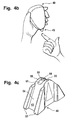
- FIGS. 4a to 4c show an analysis system in which several test fields are arranged on a tape cassette.
- the analysis system (40) has a housing (41) formed in a form that is easy for the user to handle. In a pointed front end (45) of the analysis system, the housing has an opening (46) from which emerges a test field band (43). To realize an analysis system with a test field band is on the document EP 02026242.4 to which reference is made at this point.
- the test field band (43) has regions (44) at periodic intervals, which are coated with a reagent chemistry and thus form a test field (44).
- the analysis system (40) with the front end (45) is placed on the fingertip of a patient.
- the test field band is in this case positioned so that a test field (44) rests directly on the front end (45) of the analysis system.
- the front end (45) of the analysis system is enlarged into FIG. 4 (c) shown. It can be seen that the test field band is guided within guide rails (53) of the front end (45).
- the test field band has a recess (56) in the region in which the test field is formed.
- the test chemistry of the test field is applied in an outer region (55) surrounding the recess (56).
- the band is formed integrally. As a result, the leadership of the band can be stabilized within the analysis system.
- the front portion (45) of the analysis system further has at its front end a hole (58) which is introduced in a bearing surface (51).
- a lancet exits through the hole (58) and the recess (56) of the test field, leaving a wound in there resting fingertip can be generated.
- the blood emerging from the wound is taken up by the test field regions (55), where it interacts with the reagent contained in the test field accordingly.
- the contact surface (51), on which the test field rests during the lancing and measuring process, as well as the test field band are formed optically transparent. With the aid of two light-conducting elements, which are arranged directly on the support surface (51) within the analysis system, a measurement of the test field at the sample receiving location can take place.
- test field band becomes a tape cassette principle as described in the document EP 02026242.4 is further transported until the next test field is positioned above the support surface (51).
- the analysis system is now ready to perform another lancing and measuring process. For this purpose, the system has a large number of lancets, for example.
- the result of the analysis is communicated to the user via the display (12).
Landscapes
- Health & Medical Sciences (AREA)
- Life Sciences & Earth Sciences (AREA)
- Physics & Mathematics (AREA)
- Pathology (AREA)
- General Health & Medical Sciences (AREA)
- Engineering & Computer Science (AREA)
- Veterinary Medicine (AREA)
- Biophysics (AREA)
- Biomedical Technology (AREA)
- Heart & Thoracic Surgery (AREA)
- Medical Informatics (AREA)
- Molecular Biology (AREA)
- Surgery (AREA)
- Animal Behavior & Ethology (AREA)
- Public Health (AREA)
- Hematology (AREA)
- Chemical & Material Sciences (AREA)
- Immunology (AREA)
- General Physics & Mathematics (AREA)
- Optics & Photonics (AREA)
- Analytical Chemistry (AREA)
- Biochemistry (AREA)
- Chemical Kinetics & Catalysis (AREA)
- Plasma & Fusion (AREA)
- Spectroscopy & Molecular Physics (AREA)
- Nuclear Medicine, Radiotherapy & Molecular Imaging (AREA)
- Emergency Medicine (AREA)
- Measurement Of The Respiration, Hearing Ability, Form, And Blood Characteristics Of Living Organisms (AREA)
- Investigating Or Analysing Biological Materials (AREA)
- Investigating Or Analysing Materials By The Use Of Chemical Reactions (AREA)
Priority Applications (1)
| Application Number | Priority Date | Filing Date | Title |
|---|---|---|---|
| EP12001041.8A EP2468178B1 (de) | 2003-06-06 | 2004-06-02 | Integriertes Testelement zur einmaligen Aufnahme und Analyse einer zu untersuchenden Probe |
Applications Claiming Priority (2)
| Application Number | Priority Date | Filing Date | Title |
|---|---|---|---|
| DE10325699A DE10325699B3 (de) | 2003-06-06 | 2003-06-06 | System zur Analyse einer zu untersuchenden Probe und Verwendung eines solchen Systems |
| PCT/EP2004/005924 WO2004107970A1 (de) | 2003-06-06 | 2004-06-02 | Integriertes testelement zur einmaligen aufnahme und analyse einer zu untersuchenden probe |
Related Child Applications (2)
| Application Number | Title | Priority Date | Filing Date |
|---|---|---|---|
| EP12001041.8A Division EP2468178B1 (de) | 2003-06-06 | 2004-06-02 | Integriertes Testelement zur einmaligen Aufnahme und Analyse einer zu untersuchenden Probe |
| EP12001041.8 Division-Into | 2012-02-17 |
Publications (2)
| Publication Number | Publication Date |
|---|---|
| EP1635699A1 EP1635699A1 (de) | 2006-03-22 |
| EP1635699B1 true EP1635699B1 (de) | 2012-12-19 |
Family
ID=33494864
Family Applications (2)
| Application Number | Title | Priority Date | Filing Date |
|---|---|---|---|
| EP04739508A Expired - Lifetime EP1635699B1 (de) | 2003-06-06 | 2004-06-02 | Integriertes testelement zur einmaligen aufnahme und analyse einer zu untersuchenden probe |
| EP12001041.8A Expired - Lifetime EP2468178B1 (de) | 2003-06-06 | 2004-06-02 | Integriertes Testelement zur einmaligen Aufnahme und Analyse einer zu untersuchenden Probe |
Family Applications After (1)
| Application Number | Title | Priority Date | Filing Date |
|---|---|---|---|
| EP12001041.8A Expired - Lifetime EP2468178B1 (de) | 2003-06-06 | 2004-06-02 | Integriertes Testelement zur einmaligen Aufnahme und Analyse einer zu untersuchenden Probe |
Country Status (6)
| Country | Link |
|---|---|
| US (1) | US9757059B2 (enExample) |
| EP (2) | EP1635699B1 (enExample) |
| JP (1) | JP4602323B2 (enExample) |
| CA (1) | CA2527229A1 (enExample) |
| DE (1) | DE10325699B3 (enExample) |
| WO (1) | WO2004107970A1 (enExample) |
Families Citing this family (101)
| Publication number | Priority date | Publication date | Assignee | Title |
|---|---|---|---|---|
| US6036924A (en) | 1997-12-04 | 2000-03-14 | Hewlett-Packard Company | Cassette of lancet cartridges for sampling blood |
| US6391005B1 (en) | 1998-03-30 | 2002-05-21 | Agilent Technologies, Inc. | Apparatus and method for penetration with shaft having a sensor for sensing penetration depth |
| DE10057832C1 (de) | 2000-11-21 | 2002-02-21 | Hartmann Paul Ag | Blutanalysegerät |
| US8641644B2 (en) | 2000-11-21 | 2014-02-04 | Sanofi-Aventis Deutschland Gmbh | Blood testing apparatus having a rotatable cartridge with multiple lancing elements and testing means |
| EP1404233B1 (en) | 2001-06-12 | 2009-12-02 | Pelikan Technologies Inc. | Self optimizing lancing device with adaptation means to temporal variations in cutaneous properties |
| US7041068B2 (en) | 2001-06-12 | 2006-05-09 | Pelikan Technologies, Inc. | Sampling module device and method |
| US7344507B2 (en) | 2002-04-19 | 2008-03-18 | Pelikan Technologies, Inc. | Method and apparatus for lancet actuation |
| US7981056B2 (en) | 2002-04-19 | 2011-07-19 | Pelikan Technologies, Inc. | Methods and apparatus for lancet actuation |
| CA2448905C (en) | 2001-06-12 | 2010-09-07 | Pelikan Technologies, Inc. | Blood sampling apparatus and method |
| WO2002100461A2 (en) | 2001-06-12 | 2002-12-19 | Pelikan Technologies, Inc. | Method and apparatus for improving success rate of blood yield from a fingerstick |
| AU2002348683A1 (en) | 2001-06-12 | 2002-12-23 | Pelikan Technologies, Inc. | Method and apparatus for lancet launching device integrated onto a blood-sampling cartridge |
| US9427532B2 (en) | 2001-06-12 | 2016-08-30 | Sanofi-Aventis Deutschland Gmbh | Tissue penetration device |
| CA2448790C (en) | 2001-06-12 | 2010-09-07 | Pelikan Technologies, Inc. | Electric lancet actuator |
| US7537571B2 (en) | 2001-06-12 | 2009-05-26 | Pelikan Technologies, Inc. | Integrated blood sampling analysis system with multi-use sampling module |
| US9795747B2 (en) | 2010-06-02 | 2017-10-24 | Sanofi-Aventis Deutschland Gmbh | Methods and apparatus for lancet actuation |
| US8337419B2 (en) | 2002-04-19 | 2012-12-25 | Sanofi-Aventis Deutschland Gmbh | Tissue penetration device |
| US9226699B2 (en) | 2002-04-19 | 2016-01-05 | Sanofi-Aventis Deutschland Gmbh | Body fluid sampling module with a continuous compression tissue interface surface |
| US7344894B2 (en) | 2001-10-16 | 2008-03-18 | Agilent Technologies, Inc. | Thermal regulation of fluidic samples within a diagnostic cartridge |
| US7004928B2 (en) | 2002-02-08 | 2006-02-28 | Rosedale Medical, Inc. | Autonomous, ambulatory analyte monitor or drug delivery device |
| US9314194B2 (en) | 2002-04-19 | 2016-04-19 | Sanofi-Aventis Deutschland Gmbh | Tissue penetration device |
| US7674232B2 (en) | 2002-04-19 | 2010-03-09 | Pelikan Technologies, Inc. | Method and apparatus for penetrating tissue |
| US7892183B2 (en) | 2002-04-19 | 2011-02-22 | Pelikan Technologies, Inc. | Method and apparatus for body fluid sampling and analyte sensing |
| US9795334B2 (en) | 2002-04-19 | 2017-10-24 | Sanofi-Aventis Deutschland Gmbh | Method and apparatus for penetrating tissue |
| US7524293B2 (en) | 2002-04-19 | 2009-04-28 | Pelikan Technologies, Inc. | Method and apparatus for penetrating tissue |
| US7374544B2 (en) | 2002-04-19 | 2008-05-20 | Pelikan Technologies, Inc. | Method and apparatus for penetrating tissue |
| US8702624B2 (en) | 2006-09-29 | 2014-04-22 | Sanofi-Aventis Deutschland Gmbh | Analyte measurement device with a single shot actuator |
| US7547287B2 (en) | 2002-04-19 | 2009-06-16 | Pelikan Technologies, Inc. | Method and apparatus for penetrating tissue |
| US7901362B2 (en) | 2002-04-19 | 2011-03-08 | Pelikan Technologies, Inc. | Method and apparatus for penetrating tissue |
| US7229458B2 (en) | 2002-04-19 | 2007-06-12 | Pelikan Technologies, Inc. | Method and apparatus for penetrating tissue |
| US7563232B2 (en) | 2002-04-19 | 2009-07-21 | Pelikan Technologies, Inc. | Method and apparatus for penetrating tissue |
| US8267870B2 (en) | 2002-04-19 | 2012-09-18 | Sanofi-Aventis Deutschland Gmbh | Method and apparatus for body fluid sampling with hybrid actuation |
| US7297122B2 (en) | 2002-04-19 | 2007-11-20 | Pelikan Technologies, Inc. | Method and apparatus for penetrating tissue |
| US7976476B2 (en) | 2002-04-19 | 2011-07-12 | Pelikan Technologies, Inc. | Device and method for variable speed lancet |
| US8221334B2 (en) | 2002-04-19 | 2012-07-17 | Sanofi-Aventis Deutschland Gmbh | Method and apparatus for penetrating tissue |
| US7491178B2 (en) | 2002-04-19 | 2009-02-17 | Pelikan Technologies, Inc. | Method and apparatus for penetrating tissue |
| US7717863B2 (en) | 2002-04-19 | 2010-05-18 | Pelikan Technologies, Inc. | Method and apparatus for penetrating tissue |
| US8579831B2 (en) | 2002-04-19 | 2013-11-12 | Sanofi-Aventis Deutschland Gmbh | Method and apparatus for penetrating tissue |
| US7331931B2 (en) | 2002-04-19 | 2008-02-19 | Pelikan Technologies, Inc. | Method and apparatus for penetrating tissue |
| US7141058B2 (en) | 2002-04-19 | 2006-11-28 | Pelikan Technologies, Inc. | Method and apparatus for a body fluid sampling device using illumination |
| US7371247B2 (en) | 2002-04-19 | 2008-05-13 | Pelikan Technologies, Inc | Method and apparatus for penetrating tissue |
| US7226461B2 (en) | 2002-04-19 | 2007-06-05 | Pelikan Technologies, Inc. | Method and apparatus for a multi-use body fluid sampling device with sterility barrier release |
| US7291117B2 (en) | 2002-04-19 | 2007-11-06 | Pelikan Technologies, Inc. | Method and apparatus for penetrating tissue |
| US7582099B2 (en) | 2002-04-19 | 2009-09-01 | Pelikan Technologies, Inc | Method and apparatus for penetrating tissue |
| US7909778B2 (en) | 2002-04-19 | 2011-03-22 | Pelikan Technologies, Inc. | Method and apparatus for penetrating tissue |
| US7410468B2 (en) | 2002-04-19 | 2008-08-12 | Pelikan Technologies, Inc. | Method and apparatus for penetrating tissue |
| US8784335B2 (en) | 2002-04-19 | 2014-07-22 | Sanofi-Aventis Deutschland Gmbh | Body fluid sampling device with a capacitive sensor |
| US7232451B2 (en) | 2002-04-19 | 2007-06-19 | Pelikan Technologies, Inc. | Method and apparatus for penetrating tissue |
| US9248267B2 (en) | 2002-04-19 | 2016-02-02 | Sanofi-Aventis Deustchland Gmbh | Tissue penetration device |
| US7648468B2 (en) | 2002-04-19 | 2010-01-19 | Pelikon Technologies, Inc. | Method and apparatus for penetrating tissue |
| US7481776B2 (en) | 2002-04-19 | 2009-01-27 | Pelikan Technologies, Inc. | Method and apparatus for penetrating tissue |
| US8574895B2 (en) | 2002-12-30 | 2013-11-05 | Sanofi-Aventis Deutschland Gmbh | Method and apparatus using optical techniques to measure analyte levels |
| US7052652B2 (en) | 2003-03-24 | 2006-05-30 | Rosedale Medical, Inc. | Analyte concentration detection devices and methods |
| WO2004107964A2 (en) | 2003-06-06 | 2004-12-16 | Pelikan Technologies, Inc. | Blood harvesting device with electronic control |
| WO2006001797A1 (en) | 2004-06-14 | 2006-01-05 | Pelikan Technologies, Inc. | Low pain penetrating |
| EP1635700B1 (en) | 2003-06-13 | 2016-03-09 | Sanofi-Aventis Deutschland GmbH | Apparatus for a point of care device |
| US8626257B2 (en) | 2003-08-01 | 2014-01-07 | Dexcom, Inc. | Analyte sensor |
| US20190357827A1 (en) | 2003-08-01 | 2019-11-28 | Dexcom, Inc. | Analyte sensor |
| US8282576B2 (en) | 2003-09-29 | 2012-10-09 | Sanofi-Aventis Deutschland Gmbh | Method and apparatus for an improved sample capture device |
| WO2005037095A1 (en) | 2003-10-14 | 2005-04-28 | Pelikan Technologies, Inc. | Method and apparatus for a variable user interface |
| US8364230B2 (en) | 2006-10-04 | 2013-01-29 | Dexcom, Inc. | Analyte sensor |
| US8364231B2 (en) | 2006-10-04 | 2013-01-29 | Dexcom, Inc. | Analyte sensor |
| US8425416B2 (en) | 2006-10-04 | 2013-04-23 | Dexcom, Inc. | Analyte sensor |
| US8425417B2 (en) | 2003-12-05 | 2013-04-23 | Dexcom, Inc. | Integrated device for continuous in vivo analyte detection and simultaneous control of an infusion device |
| US20080200788A1 (en) * | 2006-10-04 | 2008-08-21 | Dexcorn, Inc. | Analyte sensor |
| US8774886B2 (en) * | 2006-10-04 | 2014-07-08 | Dexcom, Inc. | Analyte sensor |
| WO2005065414A2 (en) | 2003-12-31 | 2005-07-21 | Pelikan Technologies, Inc. | Method and apparatus for improving fluidic flow and sample capture |
| US7822454B1 (en) | 2005-01-03 | 2010-10-26 | Pelikan Technologies, Inc. | Fluid sampling device with improved analyte detecting member configuration |
| WO2006011062A2 (en) | 2004-05-20 | 2006-02-02 | Albatros Technologies Gmbh & Co. Kg | Printable hydrogel for biosensors |
| WO2005120365A1 (en) | 2004-06-03 | 2005-12-22 | Pelikan Technologies, Inc. | Method and apparatus for a fluid sampling device |
| WO2006014410A1 (en) | 2004-07-02 | 2006-02-09 | Bayer Healthcare Llc | Light guide test sensor for use in determining an analyte in a fluid sample and methods for manufacturing the same |
| US8652831B2 (en) | 2004-12-30 | 2014-02-18 | Sanofi-Aventis Deutschland Gmbh | Method and apparatus for analyte measurement test time |
| US20060281187A1 (en) | 2005-06-13 | 2006-12-14 | Rosedale Medical, Inc. | Analyte detection devices and methods with hematocrit/volume correction and feedback control |
| US8801631B2 (en) | 2005-09-30 | 2014-08-12 | Intuity Medical, Inc. | Devices and methods for facilitating fluid transport |
| EP1928316B1 (en) | 2005-09-30 | 2014-02-26 | Intuity Medical, Inc. | Multi-site body fluid sampling and analysis cartridge |
| US7887494B2 (en) * | 2005-09-30 | 2011-02-15 | Intuity Medical, Inc. | Fluid sample transport devices and methods |
| CN101287406B (zh) * | 2005-10-15 | 2013-04-10 | 霍夫曼-拉罗奇有限公司 | 用于对体液进行检查的测试元件 |
| US8447376B2 (en) * | 2006-10-04 | 2013-05-21 | Dexcom, Inc. | Analyte sensor |
| US8478377B2 (en) | 2006-10-04 | 2013-07-02 | Dexcom, Inc. | Analyte sensor |
| US8562528B2 (en) | 2006-10-04 | 2013-10-22 | Dexcom, Inc. | Analyte sensor |
| US8298142B2 (en) | 2006-10-04 | 2012-10-30 | Dexcom, Inc. | Analyte sensor |
| US8449464B2 (en) | 2006-10-04 | 2013-05-28 | Dexcom, Inc. | Analyte sensor |
| US8275438B2 (en) | 2006-10-04 | 2012-09-25 | Dexcom, Inc. | Analyte sensor |
| US8052618B2 (en) | 2006-10-15 | 2011-11-08 | Roche Diagnostics Operations, Inc. | Diagnostic test element and process for its production |
| EP1929937A1 (de) * | 2006-12-07 | 2008-06-11 | F. Hoffmann-Roche AG | Vorrichtung und Verfahren zum Untersuchen von Körperflüssigkeiten |
| EP1992283B1 (de) * | 2007-05-16 | 2010-11-17 | Roche Diagnostics GmbH | Stechsystem |
| USD614773S1 (en) * | 2007-12-07 | 2010-04-27 | Kinetik Medical Devices, Ltd. | Blood pressure monitor |
| WO2009126900A1 (en) | 2008-04-11 | 2009-10-15 | Pelikan Technologies, Inc. | Method and apparatus for analyte detecting device |
| EP2293719B1 (en) | 2008-05-30 | 2015-09-09 | Intuity Medical, Inc. | Body fluid sampling device -- sampling site interface |
| CA3095014A1 (en) | 2008-06-06 | 2009-12-10 | Intuity Medical, Inc. | Detection meter and mode of operation |
| EP2299904B1 (en) | 2008-06-06 | 2019-09-11 | Intuity Medical, Inc. | Medical measurement method |
| US9375169B2 (en) | 2009-01-30 | 2016-06-28 | Sanofi-Aventis Deutschland Gmbh | Cam drive for managing disposable penetrating member actions with a single motor and motor and control system |
| US20100198107A1 (en) * | 2009-01-30 | 2010-08-05 | Roche Diagnostics Operations, Inc. | Integrated blood glucose meter and lancing device |
| US8919605B2 (en) | 2009-11-30 | 2014-12-30 | Intuity Medical, Inc. | Calibration material delivery devices and methods |
| US8965476B2 (en) | 2010-04-16 | 2015-02-24 | Sanofi-Aventis Deutschland Gmbh | Tissue penetration device |
| CA2803797A1 (en) | 2010-06-25 | 2011-12-29 | Intuity Medical, Inc. | Analyte monitoring methods and systems |
| US20120065487A1 (en) | 2010-09-07 | 2012-03-15 | Innova Medical Design LLC | Systems, methods, and devices for reducing the pain of glucose monitoring and insulin adminstration in diabetic patients |
| ES2847578T3 (es) | 2011-04-15 | 2021-08-03 | Dexcom Inc | Calibración avanzada de sensor de analito y detección de errores |
| CA2843945C (en) | 2011-08-03 | 2022-06-21 | Intuity Medical, Inc. | Devices and methods for body fluid sampling and analysis |
| EP3011544A4 (en) | 2013-06-21 | 2017-02-22 | Intuity Medical, Inc. | Analyte monitoring system with audible feedback |
| CN106214162A (zh) * | 2016-07-19 | 2016-12-14 | 天津华鸿科技股份有限公司 | 夹持式一次性采血针及成型工艺 |
| JP7704740B2 (ja) | 2019-09-16 | 2025-07-08 | アムジエン・インコーポレーテツド | 薬物送達デバイスの外部滅菌の方法 |
Family Cites Families (52)
| Publication number | Priority date | Publication date | Assignee | Title |
|---|---|---|---|---|
| US3878830A (en) * | 1973-05-31 | 1975-04-22 | Mediscience Technology Corp | Catheter system for blood gas monitoring |
| US4403984A (en) * | 1979-12-28 | 1983-09-13 | Biotek, Inc. | System for demand-based adminstration of insulin |
| US4360016A (en) * | 1980-07-01 | 1982-11-23 | Transidyne General Corp. | Blood collecting device |
| DK150403C (da) | 1983-07-15 | 1987-07-13 | Radiometer As | Blodproevetagningsudstyr |
| US4622974A (en) * | 1984-03-07 | 1986-11-18 | University Of Tennessee Research Corporation | Apparatus and method for in-vivo measurements of chemical concentrations |
| US4627445A (en) * | 1985-04-08 | 1986-12-09 | Garid, Inc. | Glucose medical monitoring system |
| DE3673236D1 (de) | 1985-05-17 | 1990-09-13 | Teijin Seiki Co Ltd | Garnwickelmaschine mit spindelantrieb. |
| US4981779A (en) * | 1986-06-26 | 1991-01-01 | Becton, Dickinson And Company | Apparatus for monitoring glucose |
| US4727730A (en) * | 1986-07-10 | 1988-03-01 | Medex, Inc. | Integrated optic system for monitoring blood pressure |
| US4994073A (en) | 1989-02-22 | 1991-02-19 | United States Surgical Corp. | Skin fastener |
| DE3923950A1 (de) | 1989-07-19 | 1991-01-31 | Biotechnolog Forschung Gmbh | Faseroptische sensoranordnung zur bestimmung eines analyts, insbesondere von glucose |
| US5054882A (en) * | 1990-08-10 | 1991-10-08 | Puritan-Bennett Corporation | Multiple optical fiber event sensor and method of manufacture |
| DE4041905A1 (de) * | 1990-12-27 | 1992-07-02 | Boehringer Mannheim Gmbh | Testtraeger-analysesystem |
| US5165418B1 (en) | 1992-03-02 | 1999-12-14 | Nikola I Tankovich | Blood sampling device and method using a laser |
| DE4310583A1 (de) * | 1993-03-31 | 1994-10-06 | Boehringer Mannheim Gmbh | Teststreifenanalysesystem |
| JP2630197B2 (ja) | 1993-04-28 | 1997-07-16 | 株式会社ニッショー | 血液吸出器具 |
| US5425717A (en) * | 1993-05-07 | 1995-06-20 | The Kendall Company | Epidural catheter system utilizing splittable needle |
| WO1995020344A1 (en) * | 1994-01-28 | 1995-08-03 | Ep Technologies, Inc. | System for examining cardiac tissue electrical characteristics |
| JPH07231884A (ja) * | 1994-02-22 | 1995-09-05 | Hamamatsu Photonics Kk | 血中放射能検出装置 |
| US5390671A (en) * | 1994-03-15 | 1995-02-21 | Minimed Inc. | Transcutaneous sensor insertion set |
| US5636640A (en) * | 1995-02-06 | 1997-06-10 | Volunteers For Medical Engineering | Liquid sampling and test apparatus |
| US5586553A (en) * | 1995-02-16 | 1996-12-24 | Minimed Inc. | Transcutaneous sensor insertion set |
| US5568806A (en) * | 1995-02-16 | 1996-10-29 | Minimed Inc. | Transcutaneous sensor insertion set |
| WO1997022291A1 (en) | 1995-12-19 | 1997-06-26 | Abbott Laboratories | Device for the detection of analyte and administration of a therapeutic substance |
| WO1997042888A1 (en) * | 1996-05-17 | 1997-11-20 | Mercury Diagnostics Inc. | Blood and interstitial fluid sampling device |
| DE19629656A1 (de) | 1996-07-23 | 1998-01-29 | Boehringer Mannheim Gmbh | Diagnostischer Testträger mit mehrschichtigem Testfeld und Verfahren zur Bestimmung von Analyt mit dessen Hilfe |
| US6584335B1 (en) | 1997-08-09 | 2003-06-24 | Roche Diagnostics Gmbh | Analytical device for in vivo analysis in the body of a patient |
| EP1112021A1 (en) * | 1998-09-10 | 2001-07-04 | Spectrx, Inc. | Attribute compensation for analyte detection and/or continuous monitoring |
| US6192168B1 (en) * | 1999-04-09 | 2001-02-20 | The United States Of America As Represented By The Secretary Of The Navy | Reflectively coated optical waveguide and fluidics cell integration |
| AU4659899A (en) | 1999-06-30 | 2001-01-31 | Nederlandse Organisatie Voor Toegepast- Natuurwetenschappelijk Onderzoek Tno | Pricking device, carrier and cassette comprising a plurality of lancets |
| US6228100B1 (en) | 1999-10-25 | 2001-05-08 | Steven Schraga | Multi-use lancet device |
| US7262061B2 (en) * | 1999-12-24 | 2007-08-28 | Roche Diagnostics Gmbh | Test element analysis system |
| US7260078B1 (en) | 2000-02-08 | 2007-08-21 | Siemens Aktiengesellschaft | Method and system for providing management protocol mediation in wireless communications networks |
| DE10010694A1 (de) | 2000-03-04 | 2001-09-06 | Roche Diagnostics Gmbh | Blutlanzette mit hygienischen Spitzenschutz |
| US6358748B1 (en) | 2000-09-28 | 2002-03-19 | The United States Of America As Represented By The U.S. Department Of Energy | Microbend fiber-optic chemical sensor |
| US7357794B2 (en) * | 2002-01-17 | 2008-04-15 | Medtronic Vascular, Inc. | Devices, systems and methods for acute or chronic delivery of substances or apparatus to extravascular treatment sites |
| ATE335435T1 (de) | 2001-06-08 | 2006-09-15 | Hoffmann La Roche | Entnahmevorrichtung für körperflüssigkeiten und testmedienskassette |
| DE10142232B4 (de) * | 2001-08-29 | 2021-04-29 | Roche Diabetes Care Gmbh | Verfahren zur Herstellung eines analytischen Hilfsmittels mit Lanzette und Testelement |
| US6746465B2 (en) * | 2001-12-14 | 2004-06-08 | The Regents Of The University Of California | Catheter based balloon for therapy modification and positioning of tissue |
| DE10221845A1 (de) * | 2002-05-16 | 2003-11-27 | Roche Diagnostics Gmbh | Verfahren und Reagenzsystem mit nicht-regenerierbarem Enzym-Coenzym-Komplex |
| DE10221840A1 (de) * | 2002-05-16 | 2003-11-27 | Roche Diagnostics Gmbh | Verfahren zur Herstellung von Polymerschichten |
| BR0309947B1 (pt) | 2002-05-16 | 2013-11-26 | Processo e dispositivo para produção de camadas de polímero sobre um suporte transparente, sua utilização e processo para produção de um sensor | |
| CA2446328C (en) | 2002-10-29 | 2013-12-31 | Bayer Healthcare Llc | Optical reagent format for small sample volumes |
| US7381184B2 (en) * | 2002-11-05 | 2008-06-03 | Abbott Diabetes Care Inc. | Sensor inserter assembly |
| US7731900B2 (en) | 2002-11-26 | 2010-06-08 | Roche Diagnostics Operations, Inc. | Body fluid testing device |
| EP1479344A1 (en) * | 2003-05-22 | 2004-11-24 | Roche Diagnostics GmbH | Direct monitoring of interstitial fluid composition |
| DE10302501A1 (de) | 2003-01-23 | 2004-08-05 | Roche Diagnostics Gmbh | Vorrichtung und Verfahren zur Aufnahme einer Körperflüssigkeit für Analysezwecke |
| US9414777B2 (en) * | 2004-07-13 | 2016-08-16 | Dexcom, Inc. | Transcutaneous analyte sensor |
| CN101287406B (zh) * | 2005-10-15 | 2013-04-10 | 霍夫曼-拉罗奇有限公司 | 用于对体液进行检查的测试元件 |
| EP1820441A1 (de) * | 2006-02-16 | 2007-08-22 | Roche Diagnostics GmbH | Mikronadelanordnung mit Sensor basierend auf der abgeschwächten Totalreflexion (ATR) |
| DE102007039258A1 (de) | 2007-08-17 | 2009-02-19 | Service Control Transparentmanagement Ag | Verfahren und Vorrichtung zur Datenerfassung und -übertragung |
| US20110251482A1 (en) * | 2009-10-29 | 2011-10-13 | Rox Medical, Inc. | Devices, systems and methods for enhanced visualization of the anatomy of a patient |
-
2003
- 2003-06-06 DE DE10325699A patent/DE10325699B3/de not_active Expired - Fee Related
-
2004
- 2004-06-02 EP EP04739508A patent/EP1635699B1/de not_active Expired - Lifetime
- 2004-06-02 US US10/559,547 patent/US9757059B2/en not_active Expired - Fee Related
- 2004-06-02 WO PCT/EP2004/005924 patent/WO2004107970A1/de not_active Ceased
- 2004-06-02 JP JP2006508247A patent/JP4602323B2/ja not_active Expired - Fee Related
- 2004-06-02 EP EP12001041.8A patent/EP2468178B1/de not_active Expired - Lifetime
- 2004-06-02 CA CA002527229A patent/CA2527229A1/en not_active Abandoned
Also Published As
| Publication number | Publication date |
|---|---|
| JP4602323B2 (ja) | 2010-12-22 |
| EP2468178B1 (de) | 2016-12-14 |
| CA2527229A1 (en) | 2004-12-16 |
| WO2004107970A1 (de) | 2004-12-16 |
| EP2468178A1 (de) | 2012-06-27 |
| JP2006527013A (ja) | 2006-11-30 |
| US9757059B2 (en) | 2017-09-12 |
| WO2004107970B1 (de) | 2005-03-03 |
| DE10325699B3 (de) | 2005-02-10 |
| US20060229533A1 (en) | 2006-10-12 |
| EP1635699A1 (de) | 2006-03-22 |
Similar Documents
| Publication | Publication Date | Title |
|---|---|---|
| EP1635699B1 (de) | Integriertes testelement zur einmaligen aufnahme und analyse einer zu untersuchenden probe | |
| EP1420694B1 (de) | System zur entnahme kleiner körperflüssigkeitsmengen | |
| EP1240503B1 (de) | Teststreifen-analysesystem, medizinischer teststreifen, und verfahren zur analytischen untersuchung einer probe mit hilfe eines teststreifen-analysesystems | |
| EP1879018B1 (de) | Analysesystem und Verfahren zur Analyse einer Probe auf einem analytischen Testelement | |
| CA2506942C (en) | Body fluid testing device | |
| US7731900B2 (en) | Body fluid testing device | |
| EP1736774B1 (de) | Analysesystem zur Analyse einer Probe auf einem analytischen Testelement | |
| DE19861320B4 (de) | Verfahren zur Blutprobennahme und Analyse | |
| EP2129289B1 (de) | Analysesystem zur bestimmung eines analyten in einer körperflüssigkeit und disposibles integriertes probengewinnungs- und analyseelement | |
| US20060079811A1 (en) | Test media cassette for bodily fluid testing device | |
| EP2130493A1 (de) | Analysesystem zur Bestimmung eines Analyten in einer Körperflüssigkeit, Magazin für ein Analysegerät und Verfahren zum Erzeugen einer Wunde in einem Körperteil zur Untersuchung einer austretenden Körperflüssigkeit | |
| EP1982653A1 (de) | Stechgerät und Analysegerät | |
| EP2218392B1 (de) | Stechsystem | |
| WO2008043498A1 (de) | Lanzette mit kapillarkanal | |
| DE19734618A1 (de) | Analysevorrichtung zur in vivo-Analyse im Körper eines Patienten | |
| CA2450106A1 (en) | Sampling devices and methods for bodily fluids | |
| DE102019133365A1 (de) | Anordnung zum Betrieb eines Biosensors sowie Anordnung zur Bestimmung des Glukosegehalts im Blut |
Legal Events
| Date | Code | Title | Description |
|---|---|---|---|
| PUAI | Public reference made under article 153(3) epc to a published international application that has entered the european phase |
Free format text: ORIGINAL CODE: 0009012 |
|
| 17P | Request for examination filed |
Effective date: 20060109 |
|
| AK | Designated contracting states |
Kind code of ref document: A1 Designated state(s): AT BE BG CH CY CZ DE DK EE ES FI FR GB GR HU IE IT LI LU MC NL PL PT RO SE SI SK TR |
|
| RAP1 | Party data changed (applicant data changed or rights of an application transferred) |
Owner name: ROCHE DIAGNOSTICS GMBH Owner name: F. HOFFMANN-LA ROCHE AG |
|
| DAX | Request for extension of the european patent (deleted) | ||
| 17Q | First examination report despatched |
Effective date: 20100414 |
|
| GRAP | Despatch of communication of intention to grant a patent |
Free format text: ORIGINAL CODE: EPIDOSNIGR1 |
|
| GRAS | Grant fee paid |
Free format text: ORIGINAL CODE: EPIDOSNIGR3 |
|
| GRAA | (expected) grant |
Free format text: ORIGINAL CODE: 0009210 |
|
| AK | Designated contracting states |
Kind code of ref document: B1 Designated state(s): AT BE BG CH CY CZ DE DK EE ES FI FR GB GR HU IE IT LI LU MC NL PL PT RO SE SI SK TR |
|
| REG | Reference to a national code |
Ref country code: GB Ref legal event code: FG4D Free format text: NOT ENGLISH Ref country code: DE Ref legal event code: R081 Ref document number: 502004013945 Country of ref document: DE Owner name: ROCHE DIABETES CARE GMBH, DE Free format text: FORMER OWNERS: ROCHE DIAGNOSTICS GMBH, 68305 MANNHEIM, DE; F. HOFFMANN-LA ROCHE AG, 4070 BASEL, CH |
|
| REG | Reference to a national code |
Ref country code: CH Ref legal event code: EP |
|
| REG | Reference to a national code |
Ref country code: AT Ref legal event code: REF Ref document number: 588922 Country of ref document: AT Kind code of ref document: T Effective date: 20130115 |
|
| REG | Reference to a national code |
Ref country code: DE Ref legal event code: R096 Ref document number: 502004013945 Country of ref document: DE Effective date: 20130221 |
|
| PG25 | Lapsed in a contracting state [announced via postgrant information from national office to epo] |
Ref country code: SE Free format text: LAPSE BECAUSE OF FAILURE TO SUBMIT A TRANSLATION OF THE DESCRIPTION OR TO PAY THE FEE WITHIN THE PRESCRIBED TIME-LIMIT Effective date: 20121219 Ref country code: ES Free format text: LAPSE BECAUSE OF FAILURE TO SUBMIT A TRANSLATION OF THE DESCRIPTION OR TO PAY THE FEE WITHIN THE PRESCRIBED TIME-LIMIT Effective date: 20130330 Ref country code: FI Free format text: LAPSE BECAUSE OF FAILURE TO SUBMIT A TRANSLATION OF THE DESCRIPTION OR TO PAY THE FEE WITHIN THE PRESCRIBED TIME-LIMIT Effective date: 20121219 |
|
| REG | Reference to a national code |
Ref country code: NL Ref legal event code: VDEP Effective date: 20121219 |
|
| PG25 | Lapsed in a contracting state [announced via postgrant information from national office to epo] |
Ref country code: GR Free format text: LAPSE BECAUSE OF FAILURE TO SUBMIT A TRANSLATION OF THE DESCRIPTION OR TO PAY THE FEE WITHIN THE PRESCRIBED TIME-LIMIT Effective date: 20130320 Ref country code: SI Free format text: LAPSE BECAUSE OF FAILURE TO SUBMIT A TRANSLATION OF THE DESCRIPTION OR TO PAY THE FEE WITHIN THE PRESCRIBED TIME-LIMIT Effective date: 20121219 |
|
| PG25 | Lapsed in a contracting state [announced via postgrant information from national office to epo] |
Ref country code: BG Free format text: LAPSE BECAUSE OF FAILURE TO SUBMIT A TRANSLATION OF THE DESCRIPTION OR TO PAY THE FEE WITHIN THE PRESCRIBED TIME-LIMIT Effective date: 20130319 Ref country code: SK Free format text: LAPSE BECAUSE OF FAILURE TO SUBMIT A TRANSLATION OF THE DESCRIPTION OR TO PAY THE FEE WITHIN THE PRESCRIBED TIME-LIMIT Effective date: 20121219 Ref country code: EE Free format text: LAPSE BECAUSE OF FAILURE TO SUBMIT A TRANSLATION OF THE DESCRIPTION OR TO PAY THE FEE WITHIN THE PRESCRIBED TIME-LIMIT Effective date: 20121219 Ref country code: CY Free format text: LAPSE BECAUSE OF FAILURE TO SUBMIT A TRANSLATION OF THE DESCRIPTION OR TO PAY THE FEE WITHIN THE PRESCRIBED TIME-LIMIT Effective date: 20121219 Ref country code: CZ Free format text: LAPSE BECAUSE OF FAILURE TO SUBMIT A TRANSLATION OF THE DESCRIPTION OR TO PAY THE FEE WITHIN THE PRESCRIBED TIME-LIMIT Effective date: 20121219 |
|
| PG25 | Lapsed in a contracting state [announced via postgrant information from national office to epo] |
Ref country code: NL Free format text: LAPSE BECAUSE OF FAILURE TO SUBMIT A TRANSLATION OF THE DESCRIPTION OR TO PAY THE FEE WITHIN THE PRESCRIBED TIME-LIMIT Effective date: 20121219 Ref country code: RO Free format text: LAPSE BECAUSE OF FAILURE TO SUBMIT A TRANSLATION OF THE DESCRIPTION OR TO PAY THE FEE WITHIN THE PRESCRIBED TIME-LIMIT Effective date: 20121219 Ref country code: PL Free format text: LAPSE BECAUSE OF FAILURE TO SUBMIT A TRANSLATION OF THE DESCRIPTION OR TO PAY THE FEE WITHIN THE PRESCRIBED TIME-LIMIT Effective date: 20121219 Ref country code: PT Free format text: LAPSE BECAUSE OF FAILURE TO SUBMIT A TRANSLATION OF THE DESCRIPTION OR TO PAY THE FEE WITHIN THE PRESCRIBED TIME-LIMIT Effective date: 20130419 |
|
| PLBE | No opposition filed within time limit |
Free format text: ORIGINAL CODE: 0009261 |
|
| STAA | Information on the status of an ep patent application or granted ep patent |
Free format text: STATUS: NO OPPOSITION FILED WITHIN TIME LIMIT |
|
| PG25 | Lapsed in a contracting state [announced via postgrant information from national office to epo] |
Ref country code: DK Free format text: LAPSE BECAUSE OF FAILURE TO SUBMIT A TRANSLATION OF THE DESCRIPTION OR TO PAY THE FEE WITHIN THE PRESCRIBED TIME-LIMIT Effective date: 20121219 |
|
| 26N | No opposition filed |
Effective date: 20130920 |
|
| BERE | Be: lapsed |
Owner name: ROCHE DIAGNOSTICS G.M.B.H. Effective date: 20130630 Owner name: F. HOFFMANN-LA ROCHE A.G. Effective date: 20130630 |
|
| PG25 | Lapsed in a contracting state [announced via postgrant information from national office to epo] |
Ref country code: IT Free format text: LAPSE BECAUSE OF FAILURE TO SUBMIT A TRANSLATION OF THE DESCRIPTION OR TO PAY THE FEE WITHIN THE PRESCRIBED TIME-LIMIT Effective date: 20121219 |
|
| REG | Reference to a national code |
Ref country code: DE Ref legal event code: R097 Ref document number: 502004013945 Country of ref document: DE Effective date: 20130920 |
|
| PG25 | Lapsed in a contracting state [announced via postgrant information from national office to epo] |
Ref country code: MC Free format text: LAPSE BECAUSE OF FAILURE TO SUBMIT A TRANSLATION OF THE DESCRIPTION OR TO PAY THE FEE WITHIN THE PRESCRIBED TIME-LIMIT Effective date: 20121219 |
|
| REG | Reference to a national code |
Ref country code: CH Ref legal event code: PL |
|
| GBPC | Gb: european patent ceased through non-payment of renewal fee |
Effective date: 20130602 |
|
| REG | Reference to a national code |
Ref country code: IE Ref legal event code: MM4A |
|
| REG | Reference to a national code |
Ref country code: FR Ref legal event code: ST Effective date: 20140228 |
|
| PG25 | Lapsed in a contracting state [announced via postgrant information from national office to epo] |
Ref country code: BE Free format text: LAPSE BECAUSE OF NON-PAYMENT OF DUE FEES Effective date: 20130630 |
|
| PG25 | Lapsed in a contracting state [announced via postgrant information from national office to epo] |
Ref country code: CH Free format text: LAPSE BECAUSE OF NON-PAYMENT OF DUE FEES Effective date: 20130630 Ref country code: GB Free format text: LAPSE BECAUSE OF NON-PAYMENT OF DUE FEES Effective date: 20130602 Ref country code: IE Free format text: LAPSE BECAUSE OF NON-PAYMENT OF DUE FEES Effective date: 20130602 Ref country code: LI Free format text: LAPSE BECAUSE OF NON-PAYMENT OF DUE FEES Effective date: 20130630 |
|
| PG25 | Lapsed in a contracting state [announced via postgrant information from national office to epo] |
Ref country code: FR Free format text: LAPSE BECAUSE OF NON-PAYMENT OF DUE FEES Effective date: 20130701 |
|
| REG | Reference to a national code |
Ref country code: AT Ref legal event code: MM01 Ref document number: 588922 Country of ref document: AT Kind code of ref document: T Effective date: 20130602 |
|
| PG25 | Lapsed in a contracting state [announced via postgrant information from national office to epo] |
Ref country code: AT Free format text: LAPSE BECAUSE OF NON-PAYMENT OF DUE FEES Effective date: 20130602 |
|
| PG25 | Lapsed in a contracting state [announced via postgrant information from national office to epo] |
Ref country code: TR Free format text: LAPSE BECAUSE OF FAILURE TO SUBMIT A TRANSLATION OF THE DESCRIPTION OR TO PAY THE FEE WITHIN THE PRESCRIBED TIME-LIMIT Effective date: 20121219 |
|
| PG25 | Lapsed in a contracting state [announced via postgrant information from national office to epo] |
Ref country code: LU Free format text: LAPSE BECAUSE OF NON-PAYMENT OF DUE FEES Effective date: 20130602 Ref country code: HU Free format text: LAPSE BECAUSE OF FAILURE TO SUBMIT A TRANSLATION OF THE DESCRIPTION OR TO PAY THE FEE WITHIN THE PRESCRIBED TIME-LIMIT; INVALID AB INITIO Effective date: 20040602 |
|
| REG | Reference to a national code |
Ref country code: DE Ref legal event code: R081 Ref document number: 502004013945 Country of ref document: DE Owner name: ROCHE DIABETES CARE GMBH, DE Free format text: FORMER OWNER: ROCHE DIAGNOSTICS GMBH, 68305 MANNHEIM, DE |
|
| PGFP | Annual fee paid to national office [announced via postgrant information from national office to epo] |
Ref country code: DE Payment date: 20210512 Year of fee payment: 18 |
|
| REG | Reference to a national code |
Ref country code: DE Ref legal event code: R119 Ref document number: 502004013945 Country of ref document: DE |
|
| PG25 | Lapsed in a contracting state [announced via postgrant information from national office to epo] |
Ref country code: DE Free format text: LAPSE BECAUSE OF NON-PAYMENT OF DUE FEES Effective date: 20230103 |