EP1635448A1 - Speed sensorless control of an induction machine using a PWM inverter with output LC filter - Google Patents
Speed sensorless control of an induction machine using a PWM inverter with output LC filter Download PDFInfo
- Publication number
- EP1635448A1 EP1635448A1 EP04104340A EP04104340A EP1635448A1 EP 1635448 A1 EP1635448 A1 EP 1635448A1 EP 04104340 A EP04104340 A EP 04104340A EP 04104340 A EP04104340 A EP 04104340A EP 1635448 A1 EP1635448 A1 EP 1635448A1
- Authority
- EP
- European Patent Office
- Prior art keywords
- vector
- inverter output
- inverter
- speed
- observer
- Prior art date
- Legal status (The legal status is an assumption and is not a legal conclusion. Google has not performed a legal analysis and makes no representation as to the accuracy of the status listed.)
- Granted
Links
- 230000006698 induction Effects 0.000 title claims abstract description 23
- 239000013598 vector Substances 0.000 claims abstract description 38
- 238000000034 method Methods 0.000 claims abstract description 20
- 230000006978 adaptation Effects 0.000 claims abstract description 18
- 230000004907 flux Effects 0.000 claims abstract description 13
- 239000011159 matrix material Substances 0.000 claims abstract description 4
- 238000012937 correction Methods 0.000 claims description 9
- 230000001172 regenerating effect Effects 0.000 claims description 2
- 230000001360 synchronised effect Effects 0.000 description 11
- 238000004088 simulation Methods 0.000 description 9
- 238000005259 measurement Methods 0.000 description 7
- 230000003044 adaptive effect Effects 0.000 description 5
- 230000008929 regeneration Effects 0.000 description 4
- 238000011069 regeneration method Methods 0.000 description 4
- 239000007787 solid Substances 0.000 description 4
- 230000008901 benefit Effects 0.000 description 3
- 238000006880 cross-coupling reaction Methods 0.000 description 2
- 238000010586 diagram Methods 0.000 description 2
- 238000012546 transfer Methods 0.000 description 2
- 230000001052 transient effect Effects 0.000 description 2
- 230000001133 acceleration Effects 0.000 description 1
- 230000005534 acoustic noise Effects 0.000 description 1
- 230000002238 attenuated effect Effects 0.000 description 1
- 239000003990 capacitor Substances 0.000 description 1
- 238000005094 computer simulation Methods 0.000 description 1
- 230000001419 dependent effect Effects 0.000 description 1
- 238000013461 design Methods 0.000 description 1
- 230000000694 effects Effects 0.000 description 1
- 238000005265 energy consumption Methods 0.000 description 1
- 238000005516 engineering process Methods 0.000 description 1
- 238000009434 installation Methods 0.000 description 1
- 238000009413 insulation Methods 0.000 description 1
- 238000012423 maintenance Methods 0.000 description 1
- 238000012544 monitoring process Methods 0.000 description 1
- 230000010355 oscillation Effects 0.000 description 1
- 238000005070 sampling Methods 0.000 description 1
Images



Classifications
-
- H—ELECTRICITY
- H02—GENERATION; CONVERSION OR DISTRIBUTION OF ELECTRIC POWER
- H02P—CONTROL OR REGULATION OF ELECTRIC MOTORS, ELECTRIC GENERATORS OR DYNAMO-ELECTRIC CONVERTERS; CONTROLLING TRANSFORMERS, REACTORS OR CHOKE COILS
- H02P21/00—Arrangements or methods for the control of electric machines by vector control, e.g. by control of field orientation
- H02P21/13—Observer control, e.g. using Luenberger observers or Kalman filters
Definitions
- This invention relates to a speed sensorless control method for an induction motor that is supplied by a PWM inverter through an output LC filter.
- a voltage source PWM inverter enables stepless speed and torque control of AC motors, allowing reduced energy consumption and increased control performance.
- the use of a PWM inverter not only brings advantages but also causes unwanted effects in the motor.
- the output voltage of the inverter consists of sharp-edged voltage pulses, producing bearing currents and high voltage stresses in motor insulations [1], [2].
- the oscillation at the switching frequency causes additional losses and acoustic noise. These phenomena can be eliminated by adding an LC filter to the output of the PWM inverter.
- the EMI shielding of the motor cable may be avoided if the voltage is nearly sinusoidal.
- An object of the present invention is to provide a method so as to solve the above problem.
- the object of the invention is achieved by a method, which is characterized by what is stated in the independent claim.
- the preferred embodiments of the invention are disclosed in the dependent claims.
- the method of the invention is based on the use of an adaptive full-order observer, and no additional voltage, current or speed measurements are needed for the vector control of the motor.
- the rotor speed adaptation is based on the estimation error of the inverter current.
- the rotor speed adaptation can be based on the measured inverter current due to the surprisingly noticed fact, that the quadrature components of the inverter current and the stator current are almost identical, i.e. the applied LC filter does not distort the q component of the current.
- An advantage of the method of the invention is that the induction motor can be controlled without any additional measurements even when LC filter is used in the inverter output. With the method of the invention the benefits achieved with the inverter output LC filter can be utilized in connection with a drive that uses no additional measurement or feedback signals.
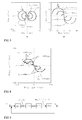
- Figure 1 shows the principle of the control system
- Figure 2 is the signal flow diagram of the cascade control
- Figures 3a, 3b and 4 show loci of current estimation error
- Figure 5 is the signal flow diagram of linearized model
- Figure 6a and 6b shows observer poles
- Figure 7 represents simulation result
- Figure 8 shows voltage and current waveforms from the simulation of Figure 7
- Figure 9 shows the experimental setup
- Figures 10 and 11 represent experimental results.
- the principle of the control system is shown in Fig. 1.
- the inverter output voltage u A is filtered by an LC filter, and the induction motor (IM) is fed by the filtered voltage u s .
- the inverter output current i A and the dc link voltage u dc are the only measured quantities, whereas the stator voltage u s , stator current i s , and the electrical angular speed ⁇ m of the rotor are estimated by an observer (the estimated quantities being marked by ' ⁇ ').
- the system is controlled by nested control loops in estimated rotor flux reference frame. It should be noted that the control arrangement presented is only one example of suitable control.
- the motor model is based on the inverse- ⁇ model [10] of the induction motor.
- Figure 2 illustrates the proposed cascade control of the system in the estimated rotor flux reference frame.
- the innermost control loop governs the inverter current i A by means of a Pl controller, and the stator voltage u s is governed by a P-type controller in the next control loop.
- decoupling terms are used to compensate the cross-couplings caused by the rotating reference frame.
- the motor control forms the two outermost control loops.
- the stator current i s is controlled by a PI-type controller with cross-coupling compensation, and the rotor speed is governed by a PI-controller.
- a PI-type rotor flux controller is used. It should be noted, however, that the presented control system is provided only as an example.
- the system states are estimated by means of a full-order observer.
- the electrical angular speed of the rotor, included in the state space representation (7), is estimated using an adaptation mechanism.
- the conventional speed adaptation law for the induction motor [7] is modified for the case where an LC filter is used.
- the estimation error of the inverter current is used for the speed adaptation, instead of the estimation error of the stator current as in the prior art systems.
- the idea of a rotated current estimation error [9], [11] is adopted.
- K P and K i are real adaptation gains
- the angle ⁇ changes the direction of the error projection.
- the digital implementation of the adaptive full-order observer is based on a simple symmetric Euler method [12].
- the inverter output current vector i A and the inverter output voltage vector u A are determined. These determinations are normal current and voltage measurements.
- the inverter output voltage vector u A is replaced in equation (9) by its reference u A,ref ⁇ Typically only two phase currents are measured to obtain the current vector.
- the output voltage of the inverter can be determined together from information of the states of the output switches and from voltage of the intermediate circuit.
- Method of the invention further comprises a step of forming a full-order observer having a system matrix ⁇ and gain vector K as explained above.
- the observer produces the estimated rotor flux linkage vector ⁇ R , the estimated stator current vector î s , the estimated stator voltage vector û s and the estimated inverter output current vector î A . These estimates can be used in the motor control in normal manner.
- the difference of them can be used in a speed adaptation loop, which produces an estimate for the electrical angular speed ⁇ m of the induction machine.
- the speed adaptation law corrects the estimate of the angular speed so that the determined and estimated current vectors are similar.
- the derivative of estimation error (13) is set to zero.
- the estimated rotor flux is constant and the synchronous frequency ⁇ s is 0.1 p.u. in Fig. 3a and 0.8 p.u. in Fig. 3b.
- the rotor speed estimate is calculated according to the imaginary part of the current estimation error.
- This kind of adaptation law works well in the motoring mode (where ⁇ s ⁇ r > 0), but at low synchronous speeds in the regeneration mode ( ⁇ s ⁇ r ⁇ 0), the imaginary part of the current estimation error changes its sign at a certain slip angular frequency as can be seen in Fig. 3(a). Beyond this point, the estimated rotor speed is corrected to the wrong direction, leading to unstable operation. This problem is not encountered at high synchronous speeds, as can seen in Fig. 3(b).
- the unstable operation can be avoided if the real part of the current estimation error is also taken into account in the speed adaptation.
- the current estimation error is rotated by a factor e - j ⁇ .
- ⁇ max is the maximum correction angle and ⁇ ⁇ is the limit for the synchronous angular frequency after which the correction is not used.
- Fig. 4 The influence of the angle correction is shown in Fig. 4.
- the current error vector is rotated clockwise and the estimated rotor speed is corrected to the right direction.
- Figure 4 shows loci of current estimation error as slip varies from negative rated slip to positive rated slip for various rotor speed estimation error values between -0.005 p.u. and 0.005 p.u.
- the synchronous angular frequency 0.1 p.u.
- the current error is rotated at negative slip angular frequencies (dashed curves).
- the dynamic behavior of the speed-adaptive observer can be analyzed via linearization.
- the operating point is set by the equilibrium quantities: the rotor angular speed ⁇ m0 and the synchronous angular frequency ⁇ s0 , and the rotor flux ⁇ R0 .
- Fig. 5 The resulting linearized system model for dynamic analysis is shown in Fig. 5. This model is used for investigating the pole locations of the linearized system at different operating points.
- the observer gain K affects the stability of the system.
- the adaptive observer In an induction motor drive without an LC filter, the adaptive observer is stable in the motoring mode even with zero gain [8]. However, zero gain cannot be used when an LC filter is present.
- Figure 6(a) shows the observer poles as the synchronous angular frequency ⁇ s is varied from -1 p.u. to 1 p.u. and the slip is rated.
- the adaptive observer with zero gain is unstable in the motoring mode, corresponding to the poles in the right half-plane.
- the system was investigated by computer simulation with Mat-lab/Simulink software.
- the LC filter was designed according to the design rules in [13], [14].
- the sampling frequency was equal to the switching frequency of 5 kHz.
- the bandwidths of the controllers were 500 Hz for the inverter current, 250 Hz for the stator voltage, 150 Hz for the stator current, 15 Hz for the rotor speed, and 1.5 Hz for the rotor flux.
- the speed estimate was filtered using a low-pass filter having the bandwidth of 40 Hz.
- the reference voltage u A,ref was used in the observer instead of the actual inverter output voltage u A .
- Figure 7 shows simulation results obtained for a sequence consisting of a fast acceleration from zero speed to 0.8 p.u., a rated load step, a slow speed reversal, and a stepwise load reversal to the negative rated load.
- the first subplot shows the rotor speed (solid) and its estimate (dashed).
- the second subplot shows the q component of the inverter current (solid) and its estimate (dashed).
- the third subplot shows the q component of the stator current (solid) and its estimate (dashed). It should be noted, that the solid and dashed plots are similar, meaning that the estimates are accurate.
- the experimental setup is illustrated in Fig. 9.
- the 2.2-kW four-pole induction motor was fed by a frequency converter controlled by a dSPACE DS1103 PPC/DSP board.
- the parameters of the experimental setup correspond to those given in Table I.
- In the LC filter three 3.3- ⁇ F capacitors were used in delta connection, giving the per-phase capacitance value of 9.9 ⁇ F.
- the dc-link voltage was measured, and the reference voltage obtained from the inverter current controller was used for the observer.
- the rotor speed and the shaft torque were measured only for monitoring.
- a simple current feedforward compensation for dead times and power device voltage drops was applied [15].
- a permanent magnet servo motor was used as a load machine.
- Figure 10 presents the experimental results corresponding to the simulations shown in Fig. 7.
- the measured performance corresponds well to the simulation results, but the vibrations in i Aq and i sq are pronounced at zero synchronous frequency.
- the vibrations are due to inaccurate motor parameter estimates and inverter nonidealities.
- the explanations of Figure 10 are as in Figure 7.
- the vibration can be attenuated by lowering the observer gain at low speeds.
- the speed limit after which the maximum gain is used is ⁇ d .
- the limit angular frequencies ⁇ ⁇ for the angle correction in (15) must also be changed because of the lower gain at low speeds.
- ⁇ ⁇ l and ⁇ ⁇ h are the limit angular frequencies for the angle correction at low and high speeds, respectively.
- control system is only one possible system for controlling an induction machine based on the method of the invention. It will be obvious to a person skilled in the art that, as the technology advances, the inventive concept can be implemented in various ways.
- the invention and its embodiments are not limited to the examples described above but may vary within the scope of the claims.
Landscapes
- Engineering & Computer Science (AREA)
- Power Engineering (AREA)
- Control Of Ac Motors In General (AREA)
Abstract
Description
- This invention relates to a speed sensorless control method for an induction motor that is supplied by a PWM inverter through an output LC filter.
- A voltage source PWM inverter enables stepless speed and torque control of AC motors, allowing reduced energy consumption and increased control performance. The use of a PWM inverter, however, not only brings advantages but also causes unwanted effects in the motor. The output voltage of the inverter consists of sharp-edged voltage pulses, producing bearing currents and high voltage stresses in motor insulations [1], [2]. The oscillation at the switching frequency causes additional losses and acoustic noise. These phenomena can be eliminated by adding an LC filter to the output of the PWM inverter. In addition, the EMI shielding of the motor cable may be avoided if the voltage is nearly sinusoidal.
- Adding an LC filter to a variable speed drive makes the motor control more difficult. Usually, a simple volts-per-hertz control method is chosen. Better control performance is achieved by using vector control, i.e. field oriented control. However, there are only few publications that deal with the vector control of a motor fed through an LC filter [3]-[5]. In these papers, an extra current or voltage measurement was necessary, and a speed encoder was used. In order to obtain cost savings and reliability improvements, a full-order observer was proposed in [6], making additional current or voltage measurements unnecessary.
- Recently, the speed sensorless control of ac motors has become popular. Promising estimation methods for speed sensorless induction motor drives are speed-adaptive full -order observers [7] combined with improvements in regeneration mode operation [8], [9]. However, a speed sensorless control methods for induction motor supplied through an LC filter are not yet published.
- The problem associated with the prior art control systems with output filter is the need for either the measurements of current or voltage from motor or the use of speed encoders. Both of the above solutions increase costs both for installation and maintenance on the system.
- An object of the present invention is to provide a method so as to solve the above problem. The object of the invention is achieved by a method, which is characterized by what is stated in the independent claim. The preferred embodiments of the invention are disclosed in the dependent claims.
- The method of the invention is based on the use of an adaptive full-order observer, and no additional voltage, current or speed measurements are needed for the vector control of the motor. The rotor speed adaptation is based on the estimation error of the inverter current. The rotor speed adaptation can be based on the measured inverter current due to the surprisingly noticed fact, that the quadrature components of the inverter current and the stator current are almost identical, i.e. the applied LC filter does not distort the q component of the current.
- An advantage of the method of the invention is that the induction motor can be controlled without any additional measurements even when LC filter is used in the inverter output. With the method of the invention the benefits achieved with the inverter output LC filter can be utilized in connection with a drive that uses no additional measurement or feedback signals.
- This is achieved by using a speed-adaptive observer, which is extended for the induction motor drive equipped with an LC filter, resulting in a drive where only the inverter output current and dc-link voltage are measured. A simple observer gain is used, and a speed-adaptation law basing on the estimation error of the inverter current is employed. The regeneration mode operation at low speeds is further stabilized by modifying the speed adaptation law. The vector control of the motor described in the specification is based on nested control loops.
- In the following the invention will be described in greater detail by means of preferred embodiments with reference to the attached drawings, in which
Figure 1 shows the principle of the control system,
Figure 2 is the signal flow diagram of the cascade control,
Figures 3a, 3b and 4 show loci of current estimation error,
Figure 5 is the signal flow diagram of linearized model,
Figure 6a and 6b shows observer poles,
Figure 7 represents simulation result,
Figure 8 shows voltage and current waveforms from the simulation of Figure 7,
Figure 9 shows the experimental setup, and
Figures 10 and 11 represent experimental results. - In the following first the system model and control are explained. Then attention is given to dynamic analysis of the system and simulation and experimental results are also described.
- The principle of the control system is shown in Fig. 1. The inverter output voltage u A is filtered by an LC filter, and the induction motor (IM) is fed by the filtered voltage u s . The inverter output current i A and the dc link voltage u dc are the only measured quantities, whereas the stator voltage u s , stator current i s , and the electrical angular speed ω m of the rotor are estimated by an observer (the estimated quantities being marked by '^'). The system is controlled by nested control loops in estimated rotor flux reference frame. It should be noted that the control arrangement presented is only one example of suitable control.
- In a reference frame rotating at angular frequency ω s the equations for the LC filter are


where L f is the inductance and R Lf the series resistance of the inductor, and C f is the capacitance of the filter. - The motor model is based on the inverse-Γ model [10] of the induction motor. The stator and rotor voltage equations are


respectively, where R s and R R are the stator and rotor resistances, respectively, and i R is the rotor current. The stator and rotor flux linkages are

respectively, where L' s denotes the stator transient inductance and L M is the magnetizing inductance. Based on (1)-(6), the state-space representation of the system can be written as shown in (7) and (8).

- The state vector is x = [ i A u s i s ψ R ] T , and the two time constants are defined as τ' σ =L' s /(R s +R R ) and τ r = L M /R R .
- Figure 2 illustrates the proposed cascade control of the system in the estimated rotor flux reference frame. In the LC filter control, the innermost control loop governs the inverter current i A by means of a Pl controller, and the stator voltage u s is governed by a P-type controller in the next control loop. In both control loops, decoupling terms are used to compensate the cross-couplings caused by the rotating reference frame.
- The motor control forms the two outermost control loops. The stator current i s is controlled by a PI-type controller with cross-coupling compensation, and the rotor speed is governed by a PI-controller. In addition, a PI-type rotor flux controller is used. It should be noted, however, that the presented control system is provided only as an example.
- The system states are estimated by means of a full-order observer. The electrical angular speed of the rotor, included in the state space representation (7), is estimated using an adaptation mechanism. The observer is i m-plemented in the estimated rotor flux reference frame, i.e., in a reference frame whereΨ̂ R =Ψ̂ R + j0 . The observer is given as

-


where the estimated states are marked by the symbol '^'. - The conventional speed adaptation law for the induction motor [7] is modified for the case where an LC filter is used. The estimation error of the inverter current is used for the speed adaptation, instead of the estimation error of the stator current as in the prior art systems. In order to stabilize the regeneration mode at low speeds, the idea of a rotated current estimation error [9], [11] is adopted.
- The speed-adaptation law in the estimated rotor flux reference frame is

where K P and K i are real adaptation gains, and the angle φ changes the direction of the error projection. The digital implementation of the adaptive full-order observer is based on a simple symmetric Euler method [12]. - According to the method of the invention, the inverter output current vector i A and the inverter output voltage vector u A are determined. These determinations are normal current and voltage measurements. In a practice, the inverter output voltage vector u A is replaced in equation (9) by its reference u A,ref · Typically only two phase currents are measured to obtain the current vector. The output voltage of the inverter can be determined together from information of the states of the output switches and from voltage of the intermediate circuit.
- Method of the invention further comprises a step of forming a full-order observer having a system matrix  and gain vector K as explained above. The observer produces the estimated rotor flux linkage vector ψ̂ R , the estimated stator current vector î s , the estimated stator voltage vector û s and the estimated inverter output current vector î A . These estimates can be used in the motor control in normal manner.
- Since the inverter output current is both estimated and determined, the difference of them can be used in a speed adaptation loop, which produces an estimate for the electrical angular speed ω̂mof the induction machine. Basically the speed adaptation law corrects the estimate of the angular speed so that the determined and estimated current vectors are similar.
- Surprisingly the q components of estimated stator current vector and inverter output current vector are almost identical, which makes it possible to use the inverter output current instead of stator current in the speed adaptation as explained later.
- With the method of the invention, all required information is gathered in order to control the induction machine.
- The dynamics of the estimation error x̃ = x - x̂ is obtained from (7) and (9):

where the difference between system matrices is
- For the steady-state analysis, the derivative of estimation error (13) is set to zero. The operation point is determined by the synchronous angular frequency ω s , the slip angular frequency ω r = ω s ―ω m , and the estimated rotor flux ψ̂ R . The example values of a 2.2-kW four-pole induction motor (400 V, 50 Hz), shown in Table I, were used for the following analysis.
- Figure 3 illustrates the current estimation error as the slip is varied from the negative rated slip to the positive rated slip, for various values of the rotor speed estimation error ω̃ m =ω m ―ω̂ m between -0.005 p.u. and 0.005 p.u. The estimated rotor flux is constant and the synchronous frequency ω s is 0.1 p.u. in Fig. 3a and 0.8 p.u. in Fig. 3b. The observer gain is K = [
3000s -1 0 0 0] T , and the base value of the angular frequency is 2π50 rad/s, and the rated slip frequency is ω rN = 0.05 p.u. - If the angle correction is not used in the adaptation law (12), the rotor speed estimate is calculated according to the imaginary part of the current estimation error. This kind of adaptation law works well in the motoring mode (where ω s ω r > 0), but at low synchronous speeds in the regeneration mode (ω s ω r < 0), the imaginary part of the current estimation error changes its sign at a certain slip angular frequency as can be seen in Fig. 3(a). Beyond this point, the estimated rotor speed is corrected to the wrong direction, leading to unstable operation. This problem is not encountered at high synchronous speeds, as can seen in Fig. 3(b).
- The unstable operation can be avoided if the real part of the current estimation error is also taken into account in the speed adaptation. Correspondingly, the current estimation error is rotated by a factor e-jφ . The angle φ is selected as [9]

where φ max is the maximum correction angle and ωφ is the limit for the synchronous angular frequency after which the correction is not used. - The influence of the angle correction is shown in Fig. 4. The parameter values φ max = 0.46π and ωφ = 0.75 p.u. are used in this example. In the regeneration-mode operation, the current error vector is rotated clockwise and the estimated rotor speed is corrected to the right direction.
- Figure 4 shows loci of current estimation error as slip varies from negative rated slip to positive rated slip for various rotor speed estimation error values between -0.005 p.u. and 0.005 p.u. The synchronous angular frequency 0.1 p.u. The current error is rotated at negative slip angular frequencies (dashed curves).
- The dynamic behavior of the speed-adaptive observer can be analyzed via linearization. The operating point is set by the equilibrium quantities: the rotor angular speed ω m0 and the synchronous angular frequency ω s0 , and the rotor flux ψ R0 . The linearized estimation error is

- The transfer function from the speed estimation error to the inverter current estimation error obtained from (16) is

- Based on (12), the transfer function from the imaginary part of the rotated inverter current error, Im{(i A -î A )e -jφ }, to the speed estimate, ω̂ m , is

- The resulting linearized system model for dynamic analysis is shown in Fig. 5. This model is used for investigating the pole locations of the linearized system at different operating points.
- The observer gain K affects the stability of the system. In an induction motor drive without an LC filter, the adaptive observer is stable in the motoring mode even with zero gain [8]. However, zero gain cannot be used when an LC filter is present. Figure 6(a) shows the observer poles as the synchronous angular frequency ω s is varied from -1 p.u. to 1 p.u. and the slip is rated. The adaptive observer with zero gain is unstable in the motoring mode, corresponding to the poles in the right half-plane.
- In order to obtain a simple observer structure, the observer gain

is proposed. The poles obtained are shown in Fig. 6(b). All poles stay in the left half-plane in the whole inspected operation region. - The system was investigated by computer simulation with Mat-lab/Simulink software. The data of a 2.2-kW induction motor, given in Table I, were used for the simulations. The LC filter was designed according to the design rules in [13], [14]. The sampling frequency was equal to the switching frequency of 5 kHz. The bandwidths of the controllers were 500 Hz for the inverter current, 250 Hz for the stator voltage, 150 Hz for the stator current, 15 Hz for the rotor speed, and 1.5 Hz for the rotor flux. The speed estimate was filtered using a low-pass filter having the bandwidth of 40 Hz. The reference voltage u A,ref was used in the observer instead of the actual inverter output voltage u A . The observer gain was K = [
3000s -1 0 0 0] T , and the adaptation gains were chosen as K p = 10 (As)-1 and K i = 20000 (As2)-1. - Figure 7 shows simulation results obtained for a sequence consisting of a fast acceleration from zero speed to 0.8 p.u., a rated load step, a slow speed reversal, and a stepwise load reversal to the negative rated load. The motor was in the regenerating mode between t = 7.6 s and t = 12 s. During the rest of the sequence, the motor was in the motoring mode with the exception of a short time in the plugging mode during the speed reversal. The first subplot shows the rotor speed (solid) and its estimate (dashed). The second subplot shows the q component of the inverter current (solid) and its estimate (dashed). The third subplot shows the q component of the stator current (solid) and its estimate (dashed). It should be noted, that the solid and dashed plots are similar, meaning that the estimates are accurate.
- Slow speed reversals at load are difficult for sensorless induction motor drives. Although the exact motor and filter parameters are used in the simulation, small vibrations appear in i Aq and i sq at t = 7.8 s when the synchronous frequency is zero. More problems are encountered if slower speed reversals are needed or parameter estimates are inaccurate. It is to be noted that the q components of the inverter and stator currents are nearly equal, which makes it possible to use i Aq in the speed adaptation law instead of i s q as in the prior art systems. The voltage and current waveforms before and after the LC filter are illustrated in detail in Fig. 8. The stator voltage and current are nearly sinusoidal. The first subplot shows the inverter output voltage (phase-to-phase) and the stator voltage (phase-to-phase). The second subplot shows the inverter current and the stator current.
- The experimental setup is illustrated in Fig. 9. The 2.2-kW four-pole induction motor was fed by a frequency converter controlled by a dSPACE DS1103 PPC/DSP board. The parameters of the experimental setup correspond to those given in Table I. In the LC filter three 3.3-µF capacitors were used in delta connection, giving the per-phase capacitance value of 9.9 µF. The dc-link voltage was measured, and the reference voltage obtained from the inverter current controller was used for the observer. The rotor speed and the shaft torque were measured only for monitoring. A simple current feedforward compensation for dead times and power device voltage drops was applied [15]. A permanent magnet servo motor was used as a load machine.
- Figure 10 presents the experimental results corresponding to the simulations shown in Fig. 7. The measured performance corresponds well to the simulation results, but the vibrations in i Aq and i sq are pronounced at zero synchronous frequency. The vibrations are due to inaccurate motor parameter estimates and inverter nonidealities. The explanations of Figure 10 are as in Figure 7.
- The vibration can be attenuated by lowering the observer gain at low speeds. The observer gain is selected as

where k 1l and k 1h are the minimum and the maximum gains. The speed limit after which the maximum gain is used is ω d . The limit angular frequencies ωφ for the angle correction in (15) must also be changed because of the lower gain at low speeds. In order to avoid stepwise changes, the limit is selected as
where ωφl and ωφh are the limit angular frequencies for the angle correction at low and high speeds, respectively. - Experimental results obtained for the modified observer gain and angle correction are shown in Fig. 11. The parameters in (20) and (21) were k 1l = 1000 s-1, k 1h = 3000 s-1, ω φl = 0.4 p.u., ω φh = 0.75 p.u., and ω d = 0.38 p.u. The explanations of Figure 11 are as in Figure 7.
- The vibrations at the zero synchronous speed are reduced significantly, but not totally removed.
- It should be noted, that the described control system is only one possible system for controlling an induction machine based on the method of the invention. It will be obvious to a person skilled in the art that, as the technology advances, the inventive concept can be implemented in various ways. The invention and its embodiments are not limited to the examples described above but may vary within the scope of the claims.
TABLE I PARAMETERS OF THE MOTOR AND THE LC FILTER Motor Parameters Stator resistance Rs 3.67 Ω Rotor resistance RR 1.65 Ω Stator transient inductance L's 0.0209H Magnetizing inductance LM 0.264 H Total moment of inertia J 0.0155 kgm2 Rated speed nN 1430 r/min Rated (base) current IN 5.0 A Rated torque TN 14.6 Nm LC Filter Parameters Inductance L f8 mH Capacitance Cf 9.9 µF Series resistance RIf 0.1 Ω - [1] D.F. Busse, J.M. Erdman, R.J. Kerkman, D.W. Schlegel, and G.L. Skibinski, "The effects of PWM voltage source inverters on the mechanical performance of rolling bearings," IEEE Trans. Ind. Applicat., vol. 33, Mar./Apr. 1997, pp. 567-576.
- [2] A. von Jouanne, P. Enjeti, and W. Gray, "The effect of long motor leads on PWM inverter fed AC motor drive systems," in Proc. IEEE APEC, vol. 2, Dallas, TX, Mar. 1995, pp. 592-597.
- [3] M. Kojima, K. Hirabayashi, Y. Kawabata, E.C. Ejiogu, and T. Kawabata, "Novel vector control system using deadbeat-controlled PWM inverter with output LC filter," IEEE Trans. Ind. Applicat. vol. 40, Jan./Feb. 2004, pp. 162-169.
- [4] A. Nabae, H. Nakano, and Y. Okamura, "A novel control strategy of the inverter with sinusoidal voltage and current outputs," in Proc. IEEE PESC'94, vol. 1, Taipei, Taiwan, June 1994, pp. 154-159.
- [5] R. Seliga and W. Koczara, "Multiloop feedback control strategy in sinewave voltage inverter for an adjustable speed cage induction motor drive system," in Proc. EPE 2001, Graz, Austria, Aug. 2001, CD-ROM.
- [6] J. Salomäki and J. Luomi, "Vector control of an induction motor fed by a PWM inverter with output LC filter," in Proc. NORPIE/2004, Trondheim, Norway, June 2004, CD-ROM.
- [7] H. Kubota, K. Matsuse, and T. Nakano, "DSP-based speed adaptive flux observer of induction motor," IEEE Trans. Ind. Applicat., vol. 29, Mar./Apr. 1993, pp. 344-348.
- [8] H. Kubota, I. Sato, Y. Tamura, K. Matsuse, H. Ohta and Y. Hori, "Regenerating-mode low-speed operation of sensorless induction motor drive with adaptive observer," IEEE Trans. Ind. Applicat., vol. 38, July/Aug. 2002, pp. 1081-1086.
- [9] M. Hinkkanen and J. Luomi, "Stabilization of the regenerating mode of full-order flux observers for sensorless induction motors," in Proc. IEEE IEMDC'03, Madison, WI, June 2003.
- [10] G.R. Slemon, "Modelling of induction machines for electric drives," IEEE Trans. Ind. Applicat., vol. 25, Nov./Dec. 1989, pp. 1126-1131.
- [11] M. Hasegawa and K. Matsui, "Robust adaptive full-order observer design with novel adaptive scheme for speed sensorless vector controlled induction motors," in Proc. IEEE IECON '02, Sevilla, Spain, Nov. 2002.
- [12] J. Niiranen, "Fast and accurate symmetric Euler algorithm for electromechanical simulations," in Proc. Electrimacs'99, Lisboa, Portugal, Sept. 1999, pp. 71-78.
- [13] J. Steinke, C. Stulz, and P. Pohjalainen, "Use of a LC filter to achieve a motor friendly performance of the PWM voltage source inverter," in Proc. IEEE IEMDC'97, Milwaukee, WI, May 1997, pp. TA2/4.1-TA2/4.3.
- [14] C. Xiyou, Y. Bin, and G. Yu, "The engineering design and the optimization of inverter output RLC filter in AC motor drive system," in Proc. IEEE IECON'02, vol. 1, Sevilla, Spain, Nov. 2002, pp. 175-180.
- [15] J. K. Pedersen, F. Blaabjerg, J. W. Jensen, and P. Thogersen, "An ideal PWM-VSI inverter with feedforward and feedback compensation," in Proc. EPE'93, vol. 4, Brighton, U.K., Sept. 1993, pp. 312-318.
Claims (3)
- A method of controlling of an induction machine using an inverter with output LC filter, characterized by the steps of
determining the inverter output current vector (i A ),
determining the inverter output voltage vector (u A ),
forming a full-order observer having a system matrix (Â) and gain vector (K), the observer producing the estimated rotor flux linkage vector (ψ̂ R ), the estimated stator current vector ( î s ), the estimated stator voltage vector ( û s ) and the estimated inverter output current vector ( î A ),
determining the estimation error (i A -î A ) of the inverter output current vector,
forming a speed adaptation law based on estimation error of the inverter output current vector for determining the estimate for electrical angular speed (ω̂m) of the induction machine, and
controlling the induction machine based on the produced estimates and the measured inverter output current. - A method according to claim 1, characterized in that the method further comprises the steps of
defining a correction angle (φ) and
changing the direction of estimation error (i A ― î A ) according to correction angle (φ) before forming the speed adaptation law in order to keep the observer stable in the regenerating mode. - A method according to claim 1, characterized in that the determining of the inverter output voltage vector (u A ) comprises a step, in which inverter output voltage reference u A,ref is used.
Priority Applications (4)
| Application Number | Priority Date | Filing Date | Title |
|---|---|---|---|
| AT04104340T ATE349102T1 (en) | 2004-09-09 | 2004-09-09 | CONTROL WITHOUT SPEED SENSOR OF AN INDUCTION MACHINE USING A PBM INVERTER WITH LC OUTPUT FILTER |
| EP04104340A EP1635448B1 (en) | 2004-09-09 | 2004-09-09 | Speed sensorless control of an induction machine using a PWM inverter with output LC filter |
| DE602004003816T DE602004003816T2 (en) | 2004-09-09 | 2004-09-09 | Control without speed sensor of an induction machine using a PBM inverter with LC output filter |
| US11/222,180 US7084604B2 (en) | 2004-09-09 | 2005-09-09 | Speed sensorless control of an induction machine using a PWM inverter with output LC filter |
Applications Claiming Priority (1)
| Application Number | Priority Date | Filing Date | Title |
|---|---|---|---|
| EP04104340A EP1635448B1 (en) | 2004-09-09 | 2004-09-09 | Speed sensorless control of an induction machine using a PWM inverter with output LC filter |
Publications (2)
| Publication Number | Publication Date |
|---|---|
| EP1635448A1 true EP1635448A1 (en) | 2006-03-15 |
| EP1635448B1 EP1635448B1 (en) | 2006-12-20 |
Family
ID=34929556
Family Applications (1)
| Application Number | Title | Priority Date | Filing Date |
|---|---|---|---|
| EP04104340A Expired - Lifetime EP1635448B1 (en) | 2004-09-09 | 2004-09-09 | Speed sensorless control of an induction machine using a PWM inverter with output LC filter |
Country Status (4)
| Country | Link |
|---|---|
| US (1) | US7084604B2 (en) |
| EP (1) | EP1635448B1 (en) |
| AT (1) | ATE349102T1 (en) |
| DE (1) | DE602004003816T2 (en) |
Cited By (21)
| Publication number | Priority date | Publication date | Assignee | Title |
|---|---|---|---|---|
| GB2441879A (en) * | 2006-09-12 | 2008-03-19 | Hamilton Sundstrand Corp | Estimating motor terminal current in a drive system including an LC filter |
| AT511298A1 (en) * | 2011-03-28 | 2012-10-15 | Lutz Erhartt | DYNAMIC PWM CONTROL FOR TRANSFORMER-COUPLED COUNTER-TERM INVERTERS |
| CN103296960A (en) * | 2013-05-24 | 2013-09-11 | 哈尔滨工业大学 | Vector control method for single current sensor |
| EP2797220A1 (en) * | 2013-04-23 | 2014-10-29 | Rockwell Automation Technologies, Inc. | Position sensorless open loop control for motor drives with output filter and transformer |
| US9054611B2 (en) | 2013-06-29 | 2015-06-09 | Rockwell Automation Technologies, Inc. | Method and apparatus for stability control of open loop motor drive operation |
| US9124209B2 (en) | 2013-01-16 | 2015-09-01 | Rockwell Automation Technologies, Inc. | Method and apparatus for controlling power converter with inverter output filter |
| US9287812B2 (en) | 2013-06-29 | 2016-03-15 | Rockwell Automation Technologies, Inc. | Method and apparatus for stability control of open loop motor drive operation |
| US9294019B2 (en) | 2013-01-16 | 2016-03-22 | Rockwell Automation Technologies, Inc. | Method and apparatus for controlling power converter with inverter output filter |
| CN105610369A (en) * | 2016-03-04 | 2016-05-25 | 合肥工业大学 | Sliding-mode observer based flux linkage observation method of asynchronous motor |
| US9374028B2 (en) | 2014-08-22 | 2016-06-21 | Rockwell Automation Technologies, Inc. | Transition scheme for position sensorless control of AC motor drives |
| US9490738B2 (en) | 2013-01-16 | 2016-11-08 | Rockwell Automation Technologies, Inc. | Sensorless motor drive vector control |
| US9716460B2 (en) | 2015-01-28 | 2017-07-25 | Rockwell Automation Technologies, Inc. | Method and apparatus for speed reversal control of motor drive |
| WO2017159236A1 (en) * | 2016-03-16 | 2017-09-21 | Mitsubishi Electric Corporation | Method and system for controlling electric motor |
| US9774284B2 (en) | 2015-02-19 | 2017-09-26 | Rockwell Automation Technologies, Inc. | Rotor position estimation apparatus and methods |
| US9800190B2 (en) | 2016-02-03 | 2017-10-24 | Rockwell Automation Technologies, Inc. | Control of motor drives with output sinewave filter capacitor current compensation using sinewave filter transfer function |
| CN108092571A (en) * | 2018-01-17 | 2018-05-29 | 哈尔滨工业大学 | Permanent magnet synchronous motor system with LC wave filters and the method that position Sensorless Control is realized using it |
| US9985565B2 (en) | 2016-04-18 | 2018-05-29 | Rockwell Automation Technologies, Inc. | Sensorless motor drive vector control with feedback compensation for filter capacitor current |
| US10020766B2 (en) | 2016-11-15 | 2018-07-10 | Rockwell Automation Technologies, Inc. | Current control of motor drives with output sinewave filter |
| US10158314B2 (en) | 2013-01-16 | 2018-12-18 | Rockwell Automation Technologies, Inc. | Feedforward control of motor drives with output sinewave filter |
| CN109639206A (en) * | 2019-01-31 | 2019-04-16 | 上海应用技术大学 | Asynchronous machine decoupling control method and asynchronous machine based on full order observer |
| CN111064404A (en) * | 2019-03-04 | 2020-04-24 | 吉林大学 | A method for on-line identification and compensation of induction motor parameters |
Families Citing this family (21)
| Publication number | Priority date | Publication date | Assignee | Title |
|---|---|---|---|---|
| WO2006004037A1 (en) * | 2004-07-06 | 2006-01-12 | Kabushiki Kaisha Yaskawa Denki | Inverter device, and speed reducing method for ac electric motor |
| US7227326B1 (en) * | 2006-04-24 | 2007-06-05 | Rockwell Automation Technologies, Inc. | System and method for transient-based motor speed estimation with transient excitation |
| CN102474171B (en) * | 2009-08-19 | 2015-08-05 | 株式会社安川电机 | Output filter and the electric motor drive system with this output filter |
| DK2575252T3 (en) | 2011-09-29 | 2018-10-08 | Daihen Corp | Signal processor, filter, power converter for power converter circuit, connection inverter system and PWM inverter system |
| CN103036529B (en) | 2011-09-29 | 2017-07-07 | 株式会社大亨 | Signal processing devices, filters, control circuits, inverters and converter systems |
| JP5868266B2 (en) * | 2012-05-30 | 2016-02-24 | 株式会社神戸製鋼所 | Elastic deformation compensation control apparatus and control method for articulated robot |
| US20160173012A1 (en) * | 2013-01-16 | 2016-06-16 | Rockwell Automation Technologies, Inc. | Sensorless motor drive vector control with feedback compensation for filter capacitor current |
| JP6084863B2 (en) * | 2013-02-28 | 2017-02-22 | 川崎重工業株式会社 | Power converter for grid connection |
| US9595896B1 (en) | 2015-12-16 | 2017-03-14 | Rockwell Automation Technologies, Inc. | Methods and systems for sensorless closed loop motor speed and torque control |
| US9800133B2 (en) * | 2016-03-22 | 2017-10-24 | Infineon Technologies Ag | Active common mode cancellation |
| CN108616141B (en) * | 2018-03-13 | 2021-07-06 | 上海交通大学 | Power nonlinear control method of LCL grid-connected inverter in microgrid |
| CN109510539B (en) * | 2018-10-08 | 2021-03-23 | 北方工业大学 | Model prediction flux linkage control system and method based on gain matrix |
| CN109713976B (en) * | 2019-02-22 | 2020-09-25 | 清华大学 | Speed sensorless control method and device for twelve-phase permanent magnet synchronous motor |
| US11196371B2 (en) | 2020-01-10 | 2021-12-07 | DRiV Automotive Inc. | Sensorless position detection for electric motor |
| CN112260600B (en) * | 2020-10-19 | 2022-02-25 | 珠海格力电器股份有限公司 | Decoupling control method and device for asynchronous motor |
| CN113285642A (en) * | 2021-04-21 | 2021-08-20 | 武汉华海通用电气有限公司 | Method for dead-voltage-containing belt speed re-throwing system of three-phase inverter with asynchronous motor terminal |
| CN113437919A (en) * | 2021-04-21 | 2021-09-24 | 武汉华海通用电气有限公司 | Belt speed re-throwing system and method for three-phase inverter with asynchronous motor terminal without residual voltage |
| CN113452298A (en) * | 2021-05-12 | 2021-09-28 | 武汉华海通用电气有限公司 | Control system and method for full-speed operation of motor with encoder-free three-phase inverter |
| CN114744937B (en) * | 2022-05-09 | 2024-09-03 | 华中科技大学 | A method of zero-frequency ride-through of motor based on variable excitation current |
| CN114844409B (en) * | 2022-05-25 | 2026-02-13 | 中车株洲电机有限公司 | A decoupling-based vector control method, system, and related components for motors. |
| US12282045B2 (en) | 2022-12-02 | 2025-04-22 | Infineon Technologies Ag | Common mode evaluation in a differential galvanic isolation signal transmission circuit |
Family Cites Families (17)
| Publication number | Priority date | Publication date | Assignee | Title |
|---|---|---|---|---|
| US5513090A (en) * | 1994-11-15 | 1996-04-30 | Electric Power Research Institute, Inc. | Hybrid series active, parallel passive, power line conditioner for harmonic isolation between a supply and a load |
| US5686806A (en) * | 1994-12-19 | 1997-11-11 | Trans-Coil, Inc. | Low-pass filter and electronic speed control system for electric motors |
| US5670851A (en) * | 1995-03-29 | 1997-09-23 | Kabushiki Kaisha Toshiba | Power conversion control system for plural electric motors and auxiliary circuit |
| US5661390A (en) * | 1995-06-23 | 1997-08-26 | Electric Power Research Institute, Inc. | Inverter-fed motor drive with EMI suppression |
| US5646498A (en) * | 1995-08-07 | 1997-07-08 | Eaton Corporation | Conducted emission radiation suppression in inverter drives |
| JP3473276B2 (en) * | 1996-07-03 | 2003-12-02 | 松下電器産業株式会社 | Inverter device |
| JP2863833B2 (en) * | 1996-09-18 | 1999-03-03 | 岡山大学長 | Active common mode canceller |
| US6122184A (en) * | 1997-06-19 | 2000-09-19 | The Texas A&M University System | Method and system for an improved converter output filter for an induction drive system |
| DE19736786A1 (en) * | 1997-08-23 | 1999-02-25 | Asea Brown Boveri | U-converter |
| JP3361047B2 (en) * | 1998-01-30 | 2003-01-07 | 株式会社東芝 | Power supply for vehicles |
| DE19908124C2 (en) * | 1999-02-25 | 2003-04-30 | Aloys Wobben | Inverters without harmonics |
| US6208537B1 (en) * | 1999-09-28 | 2001-03-27 | Rockwell Technologies, Llc | Series resonant sinewave output filter and design methodology |
| EP1555743A1 (en) * | 2002-04-15 | 2005-07-20 | Jialin Wu | Multifunction power convertor |
| FI116178B (en) * | 2002-08-22 | 2005-09-30 | Abb Oy | Arrangement for an output inductance coil in an inverter |
| US7100717B2 (en) * | 2002-10-31 | 2006-09-05 | General Motors Corporation | Integrated electric power take-off system |
| US20050141248A1 (en) * | 2003-09-11 | 2005-06-30 | Mazumder Sudip K. | Novel efficient and reliable DC/AC converter for fuel cell power conditioning |
| US6965212B1 (en) * | 2004-11-30 | 2005-11-15 | Honeywell International Inc. | Method and apparatus for field weakening control in an AC motor drive system |
-
2004
- 2004-09-09 AT AT04104340T patent/ATE349102T1/en not_active IP Right Cessation
- 2004-09-09 DE DE602004003816T patent/DE602004003816T2/en not_active Expired - Lifetime
- 2004-09-09 EP EP04104340A patent/EP1635448B1/en not_active Expired - Lifetime
-
2005
- 2005-09-09 US US11/222,180 patent/US7084604B2/en not_active Expired - Fee Related
Non-Patent Citations (2)
| Title |
|---|
| HINKKANEN M ET AL: "Stabilization of the regenerating mode of full-order flux observers for sensorless induction motors", ELECTRIC MACHINES AND DRIVES CONFERENCE, 2003. IEMDC'03. IEEE INTERNATIONAL JUNE 1-4, 2003, PISCATAWAY, NJ, USA,IEEE, vol. 1, 1 June 2003 (2003-06-01), pages 145 - 150, XP010644417, ISBN: 0-7803-7817-2 * |
| PROC. NORPIE 2004, June 2004 (2004-06-01), TRONDHEIM,NORWAY, pages 1 - 6, XP002318926 * |
Cited By (29)
| Publication number | Priority date | Publication date | Assignee | Title |
|---|---|---|---|---|
| GB2441879B (en) * | 2006-09-12 | 2008-10-22 | Hamilton Sundstrand Corp | Methods to control high speed electric machines having a front-end emi filter attached |
| GB2441879A (en) * | 2006-09-12 | 2008-03-19 | Hamilton Sundstrand Corp | Estimating motor terminal current in a drive system including an LC filter |
| AT511298A1 (en) * | 2011-03-28 | 2012-10-15 | Lutz Erhartt | DYNAMIC PWM CONTROL FOR TRANSFORMER-COUPLED COUNTER-TERM INVERTERS |
| AT511298B1 (en) * | 2011-03-28 | 2014-06-15 | Lutz Erhartt | DYNAMIC PWM CONTROL FOR TRANSFORMER-COUPLED COUNTER-TERM INVERTERS |
| US9124209B2 (en) | 2013-01-16 | 2015-09-01 | Rockwell Automation Technologies, Inc. | Method and apparatus for controlling power converter with inverter output filter |
| US10158314B2 (en) | 2013-01-16 | 2018-12-18 | Rockwell Automation Technologies, Inc. | Feedforward control of motor drives with output sinewave filter |
| US9490738B2 (en) | 2013-01-16 | 2016-11-08 | Rockwell Automation Technologies, Inc. | Sensorless motor drive vector control |
| US9294019B2 (en) | 2013-01-16 | 2016-03-22 | Rockwell Automation Technologies, Inc. | Method and apparatus for controlling power converter with inverter output filter |
| CN104124883A (en) * | 2013-04-23 | 2014-10-29 | 洛克威尔自动控制技术股份有限公司 | Power conversion system and method of controlling power conversion system |
| US9054621B2 (en) | 2013-04-23 | 2015-06-09 | Rockwell Automation Technologies, Inc. | Position sensorless open loop control for motor drives with output filter and transformer |
| US9312779B2 (en) | 2013-04-23 | 2016-04-12 | Rockwell Automation Technologies, Inc. | Position sensorless open loop control for motor drives with output filter and transformer |
| EP2797220A1 (en) * | 2013-04-23 | 2014-10-29 | Rockwell Automation Technologies, Inc. | Position sensorless open loop control for motor drives with output filter and transformer |
| CN103296960A (en) * | 2013-05-24 | 2013-09-11 | 哈尔滨工业大学 | Vector control method for single current sensor |
| US9287812B2 (en) | 2013-06-29 | 2016-03-15 | Rockwell Automation Technologies, Inc. | Method and apparatus for stability control of open loop motor drive operation |
| US9054611B2 (en) | 2013-06-29 | 2015-06-09 | Rockwell Automation Technologies, Inc. | Method and apparatus for stability control of open loop motor drive operation |
| US9374028B2 (en) | 2014-08-22 | 2016-06-21 | Rockwell Automation Technologies, Inc. | Transition scheme for position sensorless control of AC motor drives |
| US9716460B2 (en) | 2015-01-28 | 2017-07-25 | Rockwell Automation Technologies, Inc. | Method and apparatus for speed reversal control of motor drive |
| US9774284B2 (en) | 2015-02-19 | 2017-09-26 | Rockwell Automation Technologies, Inc. | Rotor position estimation apparatus and methods |
| US9800190B2 (en) | 2016-02-03 | 2017-10-24 | Rockwell Automation Technologies, Inc. | Control of motor drives with output sinewave filter capacitor current compensation using sinewave filter transfer function |
| CN105610369B (en) * | 2016-03-04 | 2018-05-29 | 合肥工业大学 | A kind of asynchronous machine Flux Observation Method based on sliding mode observer |
| CN105610369A (en) * | 2016-03-04 | 2016-05-25 | 合肥工业大学 | Sliding-mode observer based flux linkage observation method of asynchronous motor |
| US9966891B2 (en) | 2016-03-16 | 2018-05-08 | Mitsubishi Electric Research Laboratories, Inc. | System and method for controlling speed of electric motor |
| WO2017159236A1 (en) * | 2016-03-16 | 2017-09-21 | Mitsubishi Electric Corporation | Method and system for controlling electric motor |
| US9985565B2 (en) | 2016-04-18 | 2018-05-29 | Rockwell Automation Technologies, Inc. | Sensorless motor drive vector control with feedback compensation for filter capacitor current |
| US10020766B2 (en) | 2016-11-15 | 2018-07-10 | Rockwell Automation Technologies, Inc. | Current control of motor drives with output sinewave filter |
| CN108092571A (en) * | 2018-01-17 | 2018-05-29 | 哈尔滨工业大学 | Permanent magnet synchronous motor system with LC wave filters and the method that position Sensorless Control is realized using it |
| CN108092571B (en) * | 2018-01-17 | 2021-04-13 | 哈尔滨工业大学 | A Sensorless Control System for Permanent Magnet Synchronous Motor with LC Filter |
| CN109639206A (en) * | 2019-01-31 | 2019-04-16 | 上海应用技术大学 | Asynchronous machine decoupling control method and asynchronous machine based on full order observer |
| CN111064404A (en) * | 2019-03-04 | 2020-04-24 | 吉林大学 | A method for on-line identification and compensation of induction motor parameters |
Also Published As
| Publication number | Publication date |
|---|---|
| EP1635448B1 (en) | 2006-12-20 |
| ATE349102T1 (en) | 2007-01-15 |
| DE602004003816D1 (en) | 2007-02-01 |
| US7084604B2 (en) | 2006-08-01 |
| DE602004003816T2 (en) | 2007-10-11 |
| US20060145650A1 (en) | 2006-07-06 |
Similar Documents
| Publication | Publication Date | Title |
|---|---|---|
| EP1635448B1 (en) | Speed sensorless control of an induction machine using a PWM inverter with output LC filter | |
| Salomaki et al. | Sensorless control of induction motor drives equipped with inverter output filter | |
| US7728541B2 (en) | Electric motor drive control method and apparatus | |
| US7560894B2 (en) | Method and system in connection with permanent magnet synchronous machines | |
| CN100373768C (en) | Position Sensorless Control Algorithm for AC Motors | |
| KR100655702B1 (en) | Permanent Magnet Synchronous Motor Control Method | |
| US7719226B2 (en) | Highly responsive permanent magnet motor controller | |
| JP3783159B2 (en) | Synchronous motor drive control device | |
| JP2007166690A (en) | Electric motor control device | |
| JP2003134898A (en) | Sensorless control device and control method for synchronous generator | |
| WO2000014866A1 (en) | Controller for ac motor | |
| US6979967B2 (en) | Efficiency optimization control for permanent magnet motor drive | |
| JP2006014539A (en) | Motor drive controller, control method and program | |
| CN108964556A (en) | For driving the senseless control device of permanent magnetic synchronous electrical motor | |
| JP4715576B2 (en) | Electric drive control device and electric drive control method | |
| CN112713831A (en) | Model prediction-based voltage control method for three-phase four-switch inverter permanent magnet synchronous motor system | |
| Salomaki et al. | Sensorless vector control of PMSM drives equipped with inverter output filter | |
| JPH1189297A (en) | Power converter | |
| CN108352798A (en) | Motor control assembly and the elevator for having used the motor control assembly | |
| CN112825466B (en) | Control method and system of permanent magnet synchronous motor | |
| Piippo et al. | Analysis of an adaptive observer for sensorless control of PMSM drives | |
| Salomäki et al. | Sensorless vector control of an induction motor fed by a PWM inverter through an output LC filter | |
| KR20200031779A (en) | Torque ripple reduction apparatus of electric motor | |
| JP2024069063A (en) | Magnetic pole position estimation device and magnetic pole position estimation method | |
| JP2012175776A (en) | Motor controller and motor drive system |
Legal Events
| Date | Code | Title | Description |
|---|---|---|---|
| PUAI | Public reference made under article 153(3) epc to a published international application that has entered the european phase |
Free format text: ORIGINAL CODE: 0009012 |
|
| AK | Designated contracting states |
Kind code of ref document: A1 Designated state(s): AT BE BG CH CY CZ DE DK EE ES FI FR GB GR HU IE IT LI LU MC NL PL PT RO SE SI SK TR |
|
| AX | Request for extension of the european patent |
Extension state: AL HR LT LV MK |
|
| 17P | Request for examination filed |
Effective date: 20060411 |
|
| GRAP | Despatch of communication of intention to grant a patent |
Free format text: ORIGINAL CODE: EPIDOSNIGR1 |
|
| GRAS | Grant fee paid |
Free format text: ORIGINAL CODE: EPIDOSNIGR3 |
|
| GRAA | (expected) grant |
Free format text: ORIGINAL CODE: 0009210 |
|
| AKX | Designation fees paid |
Designated state(s): AT BE BG CH CY CZ DE DK EE ES FI FR GB GR HU IE IT LI LU MC NL PL PT RO SE SI SK TR |
|
| RIN1 | Information on inventor provided before grant (corrected) |
Inventor name: SALOMAEKI, JANNE |
|
| AK | Designated contracting states |
Kind code of ref document: B1 Designated state(s): AT BE BG CH CY CZ DE DK EE ES FI FR GB GR HU IE IT LI LU MC NL PL PT RO SE SI SK TR |
|
| PG25 | Lapsed in a contracting state [announced via postgrant information from national office to epo] |
Ref country code: SK Free format text: LAPSE BECAUSE OF FAILURE TO SUBMIT A TRANSLATION OF THE DESCRIPTION OR TO PAY THE FEE WITHIN THE PRESCRIBED TIME-LIMIT Effective date: 20061220 Ref country code: CH Free format text: LAPSE BECAUSE OF FAILURE TO SUBMIT A TRANSLATION OF THE DESCRIPTION OR TO PAY THE FEE WITHIN THE PRESCRIBED TIME-LIMIT Effective date: 20061220 Ref country code: NL Free format text: LAPSE BECAUSE OF FAILURE TO SUBMIT A TRANSLATION OF THE DESCRIPTION OR TO PAY THE FEE WITHIN THE PRESCRIBED TIME-LIMIT Effective date: 20061220 Ref country code: RO Free format text: LAPSE BECAUSE OF FAILURE TO SUBMIT A TRANSLATION OF THE DESCRIPTION OR TO PAY THE FEE WITHIN THE PRESCRIBED TIME-LIMIT Effective date: 20061220 Ref country code: LI Free format text: LAPSE BECAUSE OF FAILURE TO SUBMIT A TRANSLATION OF THE DESCRIPTION OR TO PAY THE FEE WITHIN THE PRESCRIBED TIME-LIMIT Effective date: 20061220 Ref country code: AT Free format text: LAPSE BECAUSE OF FAILURE TO SUBMIT A TRANSLATION OF THE DESCRIPTION OR TO PAY THE FEE WITHIN THE PRESCRIBED TIME-LIMIT Effective date: 20061220 Ref country code: SI Free format text: LAPSE BECAUSE OF FAILURE TO SUBMIT A TRANSLATION OF THE DESCRIPTION OR TO PAY THE FEE WITHIN THE PRESCRIBED TIME-LIMIT Effective date: 20061220 Ref country code: CZ Free format text: LAPSE BECAUSE OF FAILURE TO SUBMIT A TRANSLATION OF THE DESCRIPTION OR TO PAY THE FEE WITHIN THE PRESCRIBED TIME-LIMIT Effective date: 20061220 Ref country code: PL Free format text: LAPSE BECAUSE OF FAILURE TO SUBMIT A TRANSLATION OF THE DESCRIPTION OR TO PAY THE FEE WITHIN THE PRESCRIBED TIME-LIMIT Effective date: 20061220 Ref country code: BE Free format text: LAPSE BECAUSE OF FAILURE TO SUBMIT A TRANSLATION OF THE DESCRIPTION OR TO PAY THE FEE WITHIN THE PRESCRIBED TIME-LIMIT Effective date: 20061220 Ref country code: DK Free format text: LAPSE BECAUSE OF FAILURE TO SUBMIT A TRANSLATION OF THE DESCRIPTION OR TO PAY THE FEE WITHIN THE PRESCRIBED TIME-LIMIT Effective date: 20061220 |
|
| REG | Reference to a national code |
Ref country code: GB Ref legal event code: FG4D |
|
| REG | Reference to a national code |
Ref country code: CH Ref legal event code: EP |
|
| RAP2 | Party data changed (patent owner data changed or rights of a patent transferred) |
Owner name: ABB OY |
|
| REF | Corresponds to: |
Ref document number: 602004003816 Country of ref document: DE Date of ref document: 20070201 Kind code of ref document: P |
|
| REG | Reference to a national code |
Ref country code: IE Ref legal event code: FG4D |
|
| PG25 | Lapsed in a contracting state [announced via postgrant information from national office to epo] |
Ref country code: BG Free format text: LAPSE BECAUSE OF FAILURE TO SUBMIT A TRANSLATION OF THE DESCRIPTION OR TO PAY THE FEE WITHIN THE PRESCRIBED TIME-LIMIT Effective date: 20070320 Ref country code: SE Free format text: LAPSE BECAUSE OF FAILURE TO SUBMIT A TRANSLATION OF THE DESCRIPTION OR TO PAY THE FEE WITHIN THE PRESCRIBED TIME-LIMIT Effective date: 20070320 |
|
| PG25 | Lapsed in a contracting state [announced via postgrant information from national office to epo] |
Ref country code: ES Free format text: LAPSE BECAUSE OF FAILURE TO SUBMIT A TRANSLATION OF THE DESCRIPTION OR TO PAY THE FEE WITHIN THE PRESCRIBED TIME-LIMIT Effective date: 20070331 |
|
| NLT2 | Nl: modifications (of names), taken from the european patent patent bulletin |
Owner name: ABB OY Effective date: 20070124 |
|
| PG25 | Lapsed in a contracting state [announced via postgrant information from national office to epo] |
Ref country code: PT Free format text: LAPSE BECAUSE OF FAILURE TO SUBMIT A TRANSLATION OF THE DESCRIPTION OR TO PAY THE FEE WITHIN THE PRESCRIBED TIME-LIMIT Effective date: 20070423 |
|
| ET | Fr: translation filed | ||
| NLV1 | Nl: lapsed or annulled due to failure to fulfill the requirements of art. 29p and 29m of the patents act | ||
| REG | Reference to a national code |
Ref country code: CH Ref legal event code: PL |
|
| PLBI | Opposition filed |
Free format text: ORIGINAL CODE: 0009260 |
|
| PLAX | Notice of opposition and request to file observation + time limit sent |
Free format text: ORIGINAL CODE: EPIDOSNOBS2 |
|
| 26 | Opposition filed |
Opponent name: SEW-EURODRIVE GMBH & CO. KG Effective date: 20070918 |
|
| PLBB | Reply of patent proprietor to notice(s) of opposition received |
Free format text: ORIGINAL CODE: EPIDOSNOBS3 |
|
| PG25 | Lapsed in a contracting state [announced via postgrant information from national office to epo] |
Ref country code: GR Free format text: LAPSE BECAUSE OF FAILURE TO SUBMIT A TRANSLATION OF THE DESCRIPTION OR TO PAY THE FEE WITHIN THE PRESCRIBED TIME-LIMIT Effective date: 20070321 Ref country code: MC Free format text: LAPSE BECAUSE OF NON-PAYMENT OF DUE FEES Effective date: 20070930 |
|
| PG25 | Lapsed in a contracting state [announced via postgrant information from national office to epo] |
Ref country code: IE Free format text: LAPSE BECAUSE OF NON-PAYMENT OF DUE FEES Effective date: 20070910 |
|
| PLCK | Communication despatched that opposition was rejected |
Free format text: ORIGINAL CODE: EPIDOSNREJ1 |
|
| APBM | Appeal reference recorded |
Free format text: ORIGINAL CODE: EPIDOSNREFNO |
|
| APBP | Date of receipt of notice of appeal recorded |
Free format text: ORIGINAL CODE: EPIDOSNNOA2O |
|
| APBQ | Date of receipt of statement of grounds of appeal recorded |
Free format text: ORIGINAL CODE: EPIDOSNNOA3O |
|
| PG25 | Lapsed in a contracting state [announced via postgrant information from national office to epo] |
Ref country code: EE Free format text: LAPSE BECAUSE OF FAILURE TO SUBMIT A TRANSLATION OF THE DESCRIPTION OR TO PAY THE FEE WITHIN THE PRESCRIBED TIME-LIMIT Effective date: 20061220 |
|
| APAH | Appeal reference modified |
Free format text: ORIGINAL CODE: EPIDOSCREFNO |
|
| PG25 | Lapsed in a contracting state [announced via postgrant information from national office to epo] |
Ref country code: LU Free format text: LAPSE BECAUSE OF NON-PAYMENT OF DUE FEES Effective date: 20070909 Ref country code: CY Free format text: LAPSE BECAUSE OF FAILURE TO SUBMIT A TRANSLATION OF THE DESCRIPTION OR TO PAY THE FEE WITHIN THE PRESCRIBED TIME-LIMIT Effective date: 20061220 |
|
| PG25 | Lapsed in a contracting state [announced via postgrant information from national office to epo] |
Ref country code: TR Free format text: LAPSE BECAUSE OF FAILURE TO SUBMIT A TRANSLATION OF THE DESCRIPTION OR TO PAY THE FEE WITHIN THE PRESCRIBED TIME-LIMIT Effective date: 20061220 Ref country code: HU Free format text: LAPSE BECAUSE OF FAILURE TO SUBMIT A TRANSLATION OF THE DESCRIPTION OR TO PAY THE FEE WITHIN THE PRESCRIBED TIME-LIMIT Effective date: 20070621 |
|
| APBU | Appeal procedure closed |
Free format text: ORIGINAL CODE: EPIDOSNNOA9O |
|
| PLBN | Opposition rejected |
Free format text: ORIGINAL CODE: 0009273 |
|
| STAA | Information on the status of an ep patent application or granted ep patent |
Free format text: STATUS: OPPOSITION REJECTED |
|
| 27O | Opposition rejected |
Effective date: 20081110 |
|
| PGFP | Annual fee paid to national office [announced via postgrant information from national office to epo] |
Ref country code: DE Payment date: 20140922 Year of fee payment: 11 Ref country code: FI Payment date: 20140911 Year of fee payment: 11 |
|
| PGFP | Annual fee paid to national office [announced via postgrant information from national office to epo] |
Ref country code: FR Payment date: 20140919 Year of fee payment: 11 Ref country code: GB Payment date: 20140919 Year of fee payment: 11 |
|
| PGFP | Annual fee paid to national office [announced via postgrant information from national office to epo] |
Ref country code: IT Payment date: 20140923 Year of fee payment: 11 |
|
| REG | Reference to a national code |
Ref country code: DE Ref legal event code: R119 Ref document number: 602004003816 Country of ref document: DE |
|
| PG25 | Lapsed in a contracting state [announced via postgrant information from national office to epo] |
Ref country code: IT Free format text: LAPSE BECAUSE OF NON-PAYMENT OF DUE FEES Effective date: 20150909 |
|
| GBPC | Gb: european patent ceased through non-payment of renewal fee |
Effective date: 20150909 |
|
| PG25 | Lapsed in a contracting state [announced via postgrant information from national office to epo] |
Ref country code: FI Free format text: LAPSE BECAUSE OF NON-PAYMENT OF DUE FEES Effective date: 20150909 |
|
| REG | Reference to a national code |
Ref country code: FR Ref legal event code: ST Effective date: 20160531 |
|
| PG25 | Lapsed in a contracting state [announced via postgrant information from national office to epo] |
Ref country code: GB Free format text: LAPSE BECAUSE OF NON-PAYMENT OF DUE FEES Effective date: 20150909 Ref country code: DE Free format text: LAPSE BECAUSE OF NON-PAYMENT OF DUE FEES Effective date: 20160401 |
|
| PG25 | Lapsed in a contracting state [announced via postgrant information from national office to epo] |
Ref country code: FR Free format text: LAPSE BECAUSE OF NON-PAYMENT OF DUE FEES Effective date: 20150930 |