EP1635161A2 - Testing plate - Google Patents
Testing plate Download PDFInfo
- Publication number
- EP1635161A2 EP1635161A2 EP05255118A EP05255118A EP1635161A2 EP 1635161 A2 EP1635161 A2 EP 1635161A2 EP 05255118 A EP05255118 A EP 05255118A EP 05255118 A EP05255118 A EP 05255118A EP 1635161 A2 EP1635161 A2 EP 1635161A2
- Authority
- EP
- European Patent Office
- Prior art keywords
- flow path
- light shielding
- plate substrate
- plate
- portions
- Prior art date
- Legal status (The legal status is an assumption and is not a legal conclusion. Google has not performed a legal analysis and makes no representation as to the accuracy of the status listed.)
- Withdrawn
Links
Images


Classifications
-
- B—PERFORMING OPERATIONS; TRANSPORTING
- B29—WORKING OF PLASTICS; WORKING OF SUBSTANCES IN A PLASTIC STATE IN GENERAL
- B29C—SHAPING OR JOINING OF PLASTICS; SHAPING OF MATERIAL IN A PLASTIC STATE, NOT OTHERWISE PROVIDED FOR; AFTER-TREATMENT OF THE SHAPED PRODUCTS, e.g. REPAIRING
- B29C65/00—Joining or sealing of preformed parts, e.g. welding of plastics materials; Apparatus therefor
- B29C65/02—Joining or sealing of preformed parts, e.g. welding of plastics materials; Apparatus therefor by heating, with or without pressure
- B29C65/14—Joining or sealing of preformed parts, e.g. welding of plastics materials; Apparatus therefor by heating, with or without pressure using wave energy, i.e. electromagnetic radiation, or particle radiation
- B29C65/16—Laser beams
-
- B—PERFORMING OPERATIONS; TRANSPORTING
- B01—PHYSICAL OR CHEMICAL PROCESSES OR APPARATUS IN GENERAL
- B01L—CHEMICAL OR PHYSICAL LABORATORY APPARATUS FOR GENERAL USE
- B01L3/00—Containers or dishes for laboratory use, e.g. laboratory glassware; Droppers
- B01L3/50—Containers for the purpose of retaining a material to be analysed, e.g. test tubes
- B01L3/502—Containers for the purpose of retaining a material to be analysed, e.g. test tubes with fluid transport, e.g. in multi-compartment structures
- B01L3/5027—Containers for the purpose of retaining a material to be analysed, e.g. test tubes with fluid transport, e.g. in multi-compartment structures by integrated microfluidic structures, i.e. dimensions of channels and chambers are such that surface tension forces are important, e.g. lab-on-a-chip
-
- B—PERFORMING OPERATIONS; TRANSPORTING
- B29—WORKING OF PLASTICS; WORKING OF SUBSTANCES IN A PLASTIC STATE IN GENERAL
- B29C—SHAPING OR JOINING OF PLASTICS; SHAPING OF MATERIAL IN A PLASTIC STATE, NOT OTHERWISE PROVIDED FOR; AFTER-TREATMENT OF THE SHAPED PRODUCTS, e.g. REPAIRING
- B29C65/00—Joining or sealing of preformed parts, e.g. welding of plastics materials; Apparatus therefor
- B29C65/02—Joining or sealing of preformed parts, e.g. welding of plastics materials; Apparatus therefor by heating, with or without pressure
- B29C65/14—Joining or sealing of preformed parts, e.g. welding of plastics materials; Apparatus therefor by heating, with or without pressure using wave energy, i.e. electromagnetic radiation, or particle radiation
- B29C65/16—Laser beams
- B29C65/1629—Laser beams characterised by the way of heating the interface
- B29C65/1635—Laser beams characterised by the way of heating the interface at least passing through one of the parts to be joined, i.e. laser transmission welding
-
- B—PERFORMING OPERATIONS; TRANSPORTING
- B29—WORKING OF PLASTICS; WORKING OF SUBSTANCES IN A PLASTIC STATE IN GENERAL
- B29C—SHAPING OR JOINING OF PLASTICS; SHAPING OF MATERIAL IN A PLASTIC STATE, NOT OTHERWISE PROVIDED FOR; AFTER-TREATMENT OF THE SHAPED PRODUCTS, e.g. REPAIRING
- B29C65/00—Joining or sealing of preformed parts, e.g. welding of plastics materials; Apparatus therefor
- B29C65/02—Joining or sealing of preformed parts, e.g. welding of plastics materials; Apparatus therefor by heating, with or without pressure
- B29C65/14—Joining or sealing of preformed parts, e.g. welding of plastics materials; Apparatus therefor by heating, with or without pressure using wave energy, i.e. electromagnetic radiation, or particle radiation
- B29C65/16—Laser beams
- B29C65/1677—Laser beams making use of an absorber or impact modifier
- B29C65/1683—Laser beams making use of an absorber or impact modifier coated on the article
-
- B—PERFORMING OPERATIONS; TRANSPORTING
- B29—WORKING OF PLASTICS; WORKING OF SUBSTANCES IN A PLASTIC STATE IN GENERAL
- B29C—SHAPING OR JOINING OF PLASTICS; SHAPING OF MATERIAL IN A PLASTIC STATE, NOT OTHERWISE PROVIDED FOR; AFTER-TREATMENT OF THE SHAPED PRODUCTS, e.g. REPAIRING
- B29C66/00—General aspects of processes or apparatus for joining preformed parts
- B29C66/01—General aspects dealing with the joint area or with the area to be joined
- B29C66/05—Particular design of joint configurations
- B29C66/10—Particular design of joint configurations particular design of the joint cross-sections
- B29C66/11—Joint cross-sections comprising a single joint-segment, i.e. one of the parts to be joined comprising a single joint-segment in the joint cross-section
- B29C66/112—Single lapped joints
- B29C66/1122—Single lap to lap joints, i.e. overlap joints
-
- B—PERFORMING OPERATIONS; TRANSPORTING
- B29—WORKING OF PLASTICS; WORKING OF SUBSTANCES IN A PLASTIC STATE IN GENERAL
- B29C—SHAPING OR JOINING OF PLASTICS; SHAPING OF MATERIAL IN A PLASTIC STATE, NOT OTHERWISE PROVIDED FOR; AFTER-TREATMENT OF THE SHAPED PRODUCTS, e.g. REPAIRING
- B29C66/00—General aspects of processes or apparatus for joining preformed parts
- B29C66/50—General aspects of joining tubular articles; General aspects of joining long products, i.e. bars or profiled elements; General aspects of joining single elements to tubular articles, hollow articles or bars; General aspects of joining several hollow-preforms to form hollow or tubular articles
- B29C66/51—Joining tubular articles, profiled elements or bars; Joining single elements to tubular articles, hollow articles or bars; Joining several hollow-preforms to form hollow or tubular articles
- B29C66/53—Joining single elements to tubular articles, hollow articles or bars
- B29C66/534—Joining single elements to open ends of tubular or hollow articles or to the ends of bars
- B29C66/5346—Joining single elements to open ends of tubular or hollow articles or to the ends of bars said single elements being substantially flat
- B29C66/53461—Joining single elements to open ends of tubular or hollow articles or to the ends of bars said single elements being substantially flat joining substantially flat covers and/or substantially flat bottoms to open ends of container bodies
-
- G—PHYSICS
- G01—MEASURING; TESTING
- G01N—INVESTIGATING OR ANALYSING MATERIALS BY DETERMINING THEIR CHEMICAL OR PHYSICAL PROPERTIES
- G01N21/00—Investigating or analysing materials by the use of optical means, i.e. using sub-millimetre waves, infrared, visible or ultraviolet light
- G01N21/01—Arrangements or apparatus for facilitating the optical investigation
- G01N21/03—Cuvette constructions
- G01N21/0332—Cuvette constructions with temperature control
-
- G—PHYSICS
- G01—MEASURING; TESTING
- G01N—INVESTIGATING OR ANALYSING MATERIALS BY DETERMINING THEIR CHEMICAL OR PHYSICAL PROPERTIES
- G01N21/00—Investigating or analysing materials by the use of optical means, i.e. using sub-millimetre waves, infrared, visible or ultraviolet light
- G01N21/01—Arrangements or apparatus for facilitating the optical investigation
- G01N21/03—Cuvette constructions
- G01N21/05—Flow-through cuvettes
-
- G—PHYSICS
- G01—MEASURING; TESTING
- G01N—INVESTIGATING OR ANALYSING MATERIALS BY DETERMINING THEIR CHEMICAL OR PHYSICAL PROPERTIES
- G01N21/00—Investigating or analysing materials by the use of optical means, i.e. using sub-millimetre waves, infrared, visible or ultraviolet light
- G01N21/62—Systems in which the material investigated is excited whereby it emits light or causes a change in wavelength of the incident light
- G01N21/63—Systems in which the material investigated is excited whereby it emits light or causes a change in wavelength of the incident light optically excited
- G01N21/64—Fluorescence; Phosphorescence
- G01N21/645—Specially adapted constructive features of fluorimeters
-
- B—PERFORMING OPERATIONS; TRANSPORTING
- B01—PHYSICAL OR CHEMICAL PROCESSES OR APPARATUS IN GENERAL
- B01L—CHEMICAL OR PHYSICAL LABORATORY APPARATUS FOR GENERAL USE
- B01L2300/00—Additional constructional details
- B01L2300/06—Auxiliary integrated devices, integrated components
- B01L2300/0627—Sensor or part of a sensor is integrated
- B01L2300/0636—Integrated biosensor, microarrays
-
- B—PERFORMING OPERATIONS; TRANSPORTING
- B01—PHYSICAL OR CHEMICAL PROCESSES OR APPARATUS IN GENERAL
- B01L—CHEMICAL OR PHYSICAL LABORATORY APPARATUS FOR GENERAL USE
- B01L2300/00—Additional constructional details
- B01L2300/06—Auxiliary integrated devices, integrated components
- B01L2300/0627—Sensor or part of a sensor is integrated
- B01L2300/0645—Electrodes
-
- B—PERFORMING OPERATIONS; TRANSPORTING
- B01—PHYSICAL OR CHEMICAL PROCESSES OR APPARATUS IN GENERAL
- B01L—CHEMICAL OR PHYSICAL LABORATORY APPARATUS FOR GENERAL USE
- B01L2300/00—Additional constructional details
- B01L2300/08—Geometry, shape and general structure
- B01L2300/0887—Laminated structure
-
- B—PERFORMING OPERATIONS; TRANSPORTING
- B01—PHYSICAL OR CHEMICAL PROCESSES OR APPARATUS IN GENERAL
- B01L—CHEMICAL OR PHYSICAL LABORATORY APPARATUS FOR GENERAL USE
- B01L2300/00—Additional constructional details
- B01L2300/16—Surface properties and coatings
- B01L2300/168—Specific optical properties, e.g. reflective coatings
-
- B—PERFORMING OPERATIONS; TRANSPORTING
- B01—PHYSICAL OR CHEMICAL PROCESSES OR APPARATUS IN GENERAL
- B01L—CHEMICAL OR PHYSICAL LABORATORY APPARATUS FOR GENERAL USE
- B01L2300/00—Additional constructional details
- B01L2300/18—Means for temperature control
- B01L2300/1805—Conductive heating, heat from thermostatted solids is conducted to receptacles, e.g. heating plates, blocks
- B01L2300/1827—Conductive heating, heat from thermostatted solids is conducted to receptacles, e.g. heating plates, blocks using resistive heater
-
- B—PERFORMING OPERATIONS; TRANSPORTING
- B01—PHYSICAL OR CHEMICAL PROCESSES OR APPARATUS IN GENERAL
- B01L—CHEMICAL OR PHYSICAL LABORATORY APPARATUS FOR GENERAL USE
- B01L3/00—Containers or dishes for laboratory use, e.g. laboratory glassware; Droppers
- B01L3/50—Containers for the purpose of retaining a material to be analysed, e.g. test tubes
- B01L3/502—Containers for the purpose of retaining a material to be analysed, e.g. test tubes with fluid transport, e.g. in multi-compartment structures
- B01L3/5027—Containers for the purpose of retaining a material to be analysed, e.g. test tubes with fluid transport, e.g. in multi-compartment structures by integrated microfluidic structures, i.e. dimensions of channels and chambers are such that surface tension forces are important, e.g. lab-on-a-chip
- B01L3/502707—Containers for the purpose of retaining a material to be analysed, e.g. test tubes with fluid transport, e.g. in multi-compartment structures by integrated microfluidic structures, i.e. dimensions of channels and chambers are such that surface tension forces are important, e.g. lab-on-a-chip characterised by the manufacture of the container or its components
-
- B—PERFORMING OPERATIONS; TRANSPORTING
- B29—WORKING OF PLASTICS; WORKING OF SUBSTANCES IN A PLASTIC STATE IN GENERAL
- B29C—SHAPING OR JOINING OF PLASTICS; SHAPING OF MATERIAL IN A PLASTIC STATE, NOT OTHERWISE PROVIDED FOR; AFTER-TREATMENT OF THE SHAPED PRODUCTS, e.g. REPAIRING
- B29C65/00—Joining or sealing of preformed parts, e.g. welding of plastics materials; Apparatus therefor
- B29C65/02—Joining or sealing of preformed parts, e.g. welding of plastics materials; Apparatus therefor by heating, with or without pressure
- B29C65/14—Joining or sealing of preformed parts, e.g. welding of plastics materials; Apparatus therefor by heating, with or without pressure using wave energy, i.e. electromagnetic radiation, or particle radiation
- B29C65/16—Laser beams
- B29C65/1629—Laser beams characterised by the way of heating the interface
- B29C65/1674—Laser beams characterised by the way of heating the interface making use of laser diodes
-
- B—PERFORMING OPERATIONS; TRANSPORTING
- B29—WORKING OF PLASTICS; WORKING OF SUBSTANCES IN A PLASTIC STATE IN GENERAL
- B29C—SHAPING OR JOINING OF PLASTICS; SHAPING OF MATERIAL IN A PLASTIC STATE, NOT OTHERWISE PROVIDED FOR; AFTER-TREATMENT OF THE SHAPED PRODUCTS, e.g. REPAIRING
- B29C65/00—Joining or sealing of preformed parts, e.g. welding of plastics materials; Apparatus therefor
- B29C65/02—Joining or sealing of preformed parts, e.g. welding of plastics materials; Apparatus therefor by heating, with or without pressure
- B29C65/14—Joining or sealing of preformed parts, e.g. welding of plastics materials; Apparatus therefor by heating, with or without pressure using wave energy, i.e. electromagnetic radiation, or particle radiation
- B29C65/16—Laser beams
- B29C65/1696—Laser beams making use of masks
-
- B—PERFORMING OPERATIONS; TRANSPORTING
- B29—WORKING OF PLASTICS; WORKING OF SUBSTANCES IN A PLASTIC STATE IN GENERAL
- B29C—SHAPING OR JOINING OF PLASTICS; SHAPING OF MATERIAL IN A PLASTIC STATE, NOT OTHERWISE PROVIDED FOR; AFTER-TREATMENT OF THE SHAPED PRODUCTS, e.g. REPAIRING
- B29C66/00—General aspects of processes or apparatus for joining preformed parts
- B29C66/70—General aspects of processes or apparatus for joining preformed parts characterised by the composition, physical properties or the structure of the material of the parts to be joined; Joining with non-plastics material
- B29C66/71—General aspects of processes or apparatus for joining preformed parts characterised by the composition, physical properties or the structure of the material of the parts to be joined; Joining with non-plastics material characterised by the composition of the plastics material of the parts to be joined
-
- B—PERFORMING OPERATIONS; TRANSPORTING
- B29—WORKING OF PLASTICS; WORKING OF SUBSTANCES IN A PLASTIC STATE IN GENERAL
- B29C—SHAPING OR JOINING OF PLASTICS; SHAPING OF MATERIAL IN A PLASTIC STATE, NOT OTHERWISE PROVIDED FOR; AFTER-TREATMENT OF THE SHAPED PRODUCTS, e.g. REPAIRING
- B29C66/00—General aspects of processes or apparatus for joining preformed parts
- B29C66/70—General aspects of processes or apparatus for joining preformed parts characterised by the composition, physical properties or the structure of the material of the parts to be joined; Joining with non-plastics material
- B29C66/71—General aspects of processes or apparatus for joining preformed parts characterised by the composition, physical properties or the structure of the material of the parts to be joined; Joining with non-plastics material characterised by the composition of the plastics material of the parts to be joined
- B29C66/712—General aspects of processes or apparatus for joining preformed parts characterised by the composition, physical properties or the structure of the material of the parts to be joined; Joining with non-plastics material characterised by the composition of the plastics material of the parts to be joined the composition of one of the parts to be joined being different from the composition of the other part
-
- B—PERFORMING OPERATIONS; TRANSPORTING
- B29—WORKING OF PLASTICS; WORKING OF SUBSTANCES IN A PLASTIC STATE IN GENERAL
- B29C—SHAPING OR JOINING OF PLASTICS; SHAPING OF MATERIAL IN A PLASTIC STATE, NOT OTHERWISE PROVIDED FOR; AFTER-TREATMENT OF THE SHAPED PRODUCTS, e.g. REPAIRING
- B29C66/00—General aspects of processes or apparatus for joining preformed parts
- B29C66/70—General aspects of processes or apparatus for joining preformed parts characterised by the composition, physical properties or the structure of the material of the parts to be joined; Joining with non-plastics material
- B29C66/73—General aspects of processes or apparatus for joining preformed parts characterised by the composition, physical properties or the structure of the material of the parts to be joined; Joining with non-plastics material characterised by the intensive physical properties of the material of the parts to be joined, by the optical properties of the material of the parts to be joined, by the extensive physical properties of the parts to be joined, by the state of the material of the parts to be joined or by the material of the parts to be joined being a thermoplastic or a thermoset
- B29C66/739—General aspects of processes or apparatus for joining preformed parts characterised by the composition, physical properties or the structure of the material of the parts to be joined; Joining with non-plastics material characterised by the intensive physical properties of the material of the parts to be joined, by the optical properties of the material of the parts to be joined, by the extensive physical properties of the parts to be joined, by the state of the material of the parts to be joined or by the material of the parts to be joined being a thermoplastic or a thermoset characterised by the material of the parts to be joined being a thermoplastic or a thermoset
- B29C66/7392—General aspects of processes or apparatus for joining preformed parts characterised by the composition, physical properties or the structure of the material of the parts to be joined; Joining with non-plastics material characterised by the intensive physical properties of the material of the parts to be joined, by the optical properties of the material of the parts to be joined, by the extensive physical properties of the parts to be joined, by the state of the material of the parts to be joined or by the material of the parts to be joined being a thermoplastic or a thermoset characterised by the material of the parts to be joined being a thermoplastic or a thermoset characterised by the material of at least one of the parts being a thermoplastic
- B29C66/73921—General aspects of processes or apparatus for joining preformed parts characterised by the composition, physical properties or the structure of the material of the parts to be joined; Joining with non-plastics material characterised by the intensive physical properties of the material of the parts to be joined, by the optical properties of the material of the parts to be joined, by the extensive physical properties of the parts to be joined, by the state of the material of the parts to be joined or by the material of the parts to be joined being a thermoplastic or a thermoset characterised by the material of the parts to be joined being a thermoplastic or a thermoset characterised by the material of at least one of the parts being a thermoplastic characterised by the materials of both parts being thermoplastics
-
- B—PERFORMING OPERATIONS; TRANSPORTING
- B29—WORKING OF PLASTICS; WORKING OF SUBSTANCES IN A PLASTIC STATE IN GENERAL
- B29C—SHAPING OR JOINING OF PLASTICS; SHAPING OF MATERIAL IN A PLASTIC STATE, NOT OTHERWISE PROVIDED FOR; AFTER-TREATMENT OF THE SHAPED PRODUCTS, e.g. REPAIRING
- B29C66/00—General aspects of processes or apparatus for joining preformed parts
- B29C66/80—General aspects of machine operations or constructions and parts thereof
- B29C66/83—General aspects of machine operations or constructions and parts thereof characterised by the movement of the joining or pressing tools
- B29C66/832—Reciprocating joining or pressing tools
- B29C66/8322—Joining or pressing tools reciprocating along one axis
-
- G—PHYSICS
- G01—MEASURING; TESTING
- G01N—INVESTIGATING OR ANALYSING MATERIALS BY DETERMINING THEIR CHEMICAL OR PHYSICAL PROPERTIES
- G01N21/00—Investigating or analysing materials by the use of optical means, i.e. using sub-millimetre waves, infrared, visible or ultraviolet light
- G01N21/01—Arrangements or apparatus for facilitating the optical investigation
- G01N21/03—Cuvette constructions
- G01N2021/0346—Capillary cells; Microcells
-
- G—PHYSICS
- G01—MEASURING; TESTING
- G01N—INVESTIGATING OR ANALYSING MATERIALS BY DETERMINING THEIR CHEMICAL OR PHYSICAL PROPERTIES
- G01N2201/00—Features of devices classified in G01N21/00
- G01N2201/06—Illumination; Optics
- G01N2201/064—Stray light conditioning
Definitions
- the present invention relates to a simple testing plate capable of performing, for example, a blood test and a DNA test by a medical institution or an individual, and more specifically, to a testing plate capable of more accurately performing fluorescence measurement for determining whether a biochemical reaction between probe DNA and sample DNA occurs or not.
- a testing chip for testing a material collected from the human body has been increasingly developed.
- a DNA chip where multiple kinds of DNA fragments (probes) are previously implanted in a substrate made of, for example, glass can measure expression of genes (test sample or target) collected from the human body at one time.
- test sample DNA reacts to the DNA fragments in the probe, for example, is determined by the following method.
- a test sample is previously subjected to a chemical treatment so as to contain a fluorescent dye.
- the test sample containing the fluorescent dye flows into the DNA chip, and excitation light is radiated thereon.
- the test sample is bonded to only DNA fragments having sequences corresponding to DNA sequences of the test sample, among the DNA fragments of the probe. Therefore, if excitation light is radiated, only the DNA fragments bonded to the test sample containing the fluorescent dye emits light due to the fluorescent dye. Accordingly, it is determined by the emission whether the test sample DNA reacts to the DNA fragments in the probe. By examining the sequences of the emitted DNA fragments, the kinds of DNA of the test sample are determined.
- Japanese Unexamined Patent Application Publication No. 2003-181257 discloses a cell substrate having a micro flow path capable of performing chemical analysis of liquid produced by synthesis and reaction of various kinds of liquid, or of mixing the minimum amount of liquid to decrease the amount of waste liquid.
- a resin substrate 31 and a cover 33 constituting a cell substrate are all transparent. Light is emitted to the resin substrate 31 and the cover 33, so that optical characteristics of liquid synthesized in a canal 32 provided on the resin substrate 31 are measured.
- the resin substrate 31 and the cover 33 need to be made of a material which exhibits low fluorescence.
- the resin substrate 31 and the cover 33 made of, for example, glass are used, light is not emitted at all, but a small amount of light is emitted from the resin substrate 31 and the cover 33. Therefore, there is a problem in that the light becomes a noise when a fluorescent intensity is measured.
- the resin substrate 31 or the cover 33 may be made of a material which exhibits lower fluorescence.
- the resin substrate 31 and the cover 33 need to satisfy various conditions, such as high heat resistance and ease of manufacturing, as well as low fluorescence, but there exists no material which satisfies such conditions. For this reason, it is preferable that the structure of the cell substrate, not the material forming the resin substrate or the cover, satisfy low fluorescence.
- the present invention has been finalized in view of the drawbacks inherent in the conventional testing plate, and it is an object of the present invention to provide a testing plate capable of accurately performing fluorescence measurement for determining whether a biochemical reaction between probe DNA and sample DNA occurs or not.
- a testing plate includes a plate substrate having a concave-shaped flow path; and a lid body that is joined to the plate substrate.
- light shielding portions are provided in at least a portion of the concave portion constituting the flow path and/or on a top surface of the plate substrate along the flow path.
- the light shielding portions be formed along the flow path on the top surface of the plate substrate at both sides of the flow path. Accordingly, a light shielding property can be properly improved, and the light shielding portions can be easily formed.
- the light shielding portions function as electrode portions.
- a voltage is applied to the electrode portions to generating an electrochemical reaction, such as an oxidation-reduction reaction, so that hybridization can be performed at high speed.
- each of the electrode portions is provided with terminals which project toward the inside of the concave portion from both sides of the flow path, and the terminals protruding from one side of the flow path and the terminals protruding from the other side are alternately disposed in the flow direction of the flow path. Accordingly, an electrochemical reaction, such as an oxidation-reduction can be effectively triggered.
- the light shielding portions function as heating portions. Accordingly, heating to a predetermined reaction temperature and maintenance of the reaction temperature can be easily performed, so that a predetermined reaction can be effectively triggered.
- the air inside the flow path is expanded by the heating portions, so that the material inside the flow path can be rapidly transmitted to a predetermined place, or drain liquid can be rapidly dried.
- the light shielding portions be made of a material capable of absorbing laser beams when the plate substrate and the lid body are laser-welded, and that the plate substrate and the lid body be laser-welded with the light shielding portions interposed therebetween.
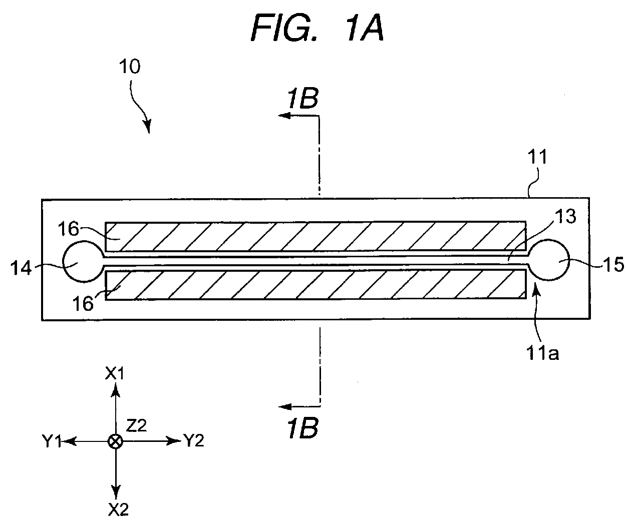
- FIG. 1A is a plan view illustrating a testing plate of the present invention.
- FIG. 1B is a cross-sectional view taken along the line IB-IB of FIG. 1A.
- FIG. 2 is a diagram explaining a method of measuring a fluorescent intensity in the present invention. Moreover, in FIG. 1, oblique lines are shown so as to highlight light shielding portions.
- a testing plate 10 shown in FIGS. 1A and 1B is a plate for performing a predetermined test where a test sample, such as blood collected from the human body, reacts to a predetermined reagent or the like.
- a test sample such as blood collected from the human body
- a predetermined reagent or the like reacts to a predetermined reagent or the like.
- the testing plate 10 is used as, for example, a DNA chip, the collected blood is subjected to a predetermined treatment so as to be used.
- the testing plate 10 has a substantially rectangular-parallelepiped shape which has a predetermined thickness to extend in the longitudinal direction (Y1-Y2 direction in FIG. 1A) perpendicular to the width direction (X1-X2 direction in FIG. 1A). Moreover, the testing plate 10 may have shapes other than the substantially rectangular-parallelepiped shape.
- the testing plate 10 is composed of a plate substrate 11 and a lid body 12.
- the plate substrate 11 and the lid body 12 are made of, for example, glass or resin. Further, the plate substrate 11 and the lid body 12 are formed of a material having a predetermined fluorescence intensity. Particularly, when the testing plate 10 is used as a DNA chip or a protein chip, it is preferable that the testing plate 10 be formed of a material, such as silica glass, polydimethylsiloxane (PDMS), or polymethyl methacrylate (PMMA), which exhibits low fluorescence and has high chemical resistance.
- PDMS polydimethylsiloxane
- PMMA polymethyl methacrylate
- the testing plate 10 When the testing plate 10 is made of resin, it is preferable that the testing plate 10 be formed by injection molding. In some cases, the testing plate 10 is subjected to hot pressing, so that a groove is formed on a top surface 12a of the plate substrate 11 to have a high aspect ratio. In addition, when the testing plate 10 is made of glass, it is molded by hot pressing.
- the plate substrate 11 and the lid body 12 may be not made of the same material. However, if they are made of the same material, there is an advantage in that the plate substrate 11 and the lid body 12 are easily joined to each other without an adhesive, for example.
- a flow path 13 having a predetermined width and length is formed in a concave shape to extend in a straight line in the Y1-Y2 direction of FIGS. 1A. Since the flow path 13 is formed in a straight line, turbulence does not occur therein when a material flows in the flow path. Moreover, the flow path 13 may have shapes other than the line shape.
- An inlet 14 for injecting a material is provided at the end of the flow path 13 in the Y1 side of FIG. 1A, and an outlet 15 for discharging the material is provided at the end of the flow path 13 in the Y2 side of FIG. 1A.
- light shielding portions 16 are provided on the top surface 11a of the plate substrate 11 along the flow path 13 in the X1 side (right side) and the X2 side (left side), respectively.
- the light shielding portions 16 are formed to have a darker color, such as black, than the plate substrate 11 and the lid body 12 so as not to reflect light. Further, the light shielding portions 16 are coated with a material which has an excellent light-shielding property, compared to the plate substrate 11 and the lid body 12. It is preferable that the light shielding portions 16 having a predetermined width be formed across the overall length of the flow path 13.
- the testing plate 10 of the present invention is used as, for example, a DNA chip.
- the testing plate 10 When the testing plate 10 is used as a DNA chip, first, a plurality of beads 21 on which probes (multiple kinds of DNA fragments) are fixed flow into the inlet 14 so as to be arranged inside the flow path 13. Since the beads 21 are made of, for example, glass or fiber, various kinds of fluorescent dyes are combined in different proportions.
- Test samples (genes collected from the human body) are injected through the inlet 14 into the flow path 13 where the beads 21 are arranged. After the test samples are filled inside the flow path 13, excitation light R is radiated to the flow path 13 from the upper direction (the Z1 direction of FIG. 2), as shown in FIG. 2.
- the test samples react and are bonded to only DNA fragments having sequences corresponding to the DNA sequences of the test sample, among multiple kinds of DNA fragments in the probe. Then, only the DNA fragments which have reacted to the test samples emit light corresponding to the fluorescent dye. When light is emitted, the sequences of the DNA fragments of the probes are examined, so that the kinds of DNA of the test samples are distinguished. Alternatively, by measuring the fluorescent intensity of fluorescent light, it is analyzed whether the test samples react or not.
- the plate substrate 11 is made of a material having a predetermined fluorescent intensity
- light having a predetermined fluorescent intensity is also emitted from the plate substrate 11 by radiation of the excitation light R.
- the light shielding portions 16 are preferably provided along the flow path 13 across the overall length of the flow path 13 in the right side and the left side of the flow path 13, respectively. Therefore, when the fluorescent intensity is measured, a small amount of light emitted from the plate substrate 11 and the lid body 12 can be also properly shielded by the light shielding portions 16, which makes it possible to improve stability of measuring the fluorescent intensity with respect to the respective beads 21 arranged in the flow path 13.
- FIG. 3 is a cross-sectional view corresponding to FIG. 1B, showing a state where the light shielding portion of the present invention is provided in another place.
- the light shielding portions 16 are provided along both sides of the flow path 13 (the X1 side and the X2 side of the drawings) only on the top surface 11a of the plate substrate 11. In the method shown in FIG. 3, however, the light shielding portions 16 are provided on all surfaces of the right side surface 13a in the X1 side, the left side surface 13b in the X2 side, and the inner bottom surface 13c in the Z2 side (downward) inside a concave portion constituting the flow path 13. In this way, the influence of light emission from the plate substrate 11 inside the flow path 13 can be prevented. Similar to the case of FIG. 1B, light emission from the respective beads 21 arranged inside the flow path 13 can be reliably perceived, so that the fluorescent intensity can be accurately measured. As a result, it can be determined whether the test sample has reacted or not.
- FIG. 4 is a plan view corresponding to FIG. 1A, and shows a modification of the testing plate of the present invention.
- the light shielding portion 16 may also be provided on the top surface 11a of the plate substrate 11 around the inlet 14 and the outlet 15, as shown in FIG. 4. Further, the light shielding portion 16 may also be provided inside the concave portion constituting the inlet 14 and the outlet 15.
- the outlet 15 is a region where the test sample and the probes react to each other, light emitted from the plate substrate 11 and the lid body 12 in the vicinity of the outlet 15 needs to be properly shielded because the outlet 15 is a test region. For this reason, as shown in FIG. 4, it is preferable that the light shielding portion 16 be provided around the outlet 15 or the inlet 14, according to the type of test.
- the light shielding portion 16 may be provided around the outlet 15 or the inlet 14, or it may be provided only inside the concave portion constituting the outlet 15 or the inlet 14.
- the light shielding portion 16 may be provided in the concave portion constituting the flow path 13 and on at least a portion of the top surface 11a of the plate substrate 11 along the flow path 13. However, it is preferable that the light shielding portion 16 be formed along the flow path 13 on the top surface 11a of the plate substrate 11 in both sides of the flow path 13. Accordingly, the light shielding portion 16 can be easily formed.
- the light shielding portion 16 be also provided inside the concave portion constituting the flow path 13, but the light shielding portion 16 needs to be formed so that the flow path 13 is not closed.
- the light shielding portion 16 may be made of, for example, carbon or zinc oxide.
- FIG. 5A is a plan view illustrating the plate substrate on which a modification of the light shielding portion of the present invention is provided
- FIG. 5B is a cross-sectional view taken along the line VB-VB of FIG. 5A.
- the light shielding portion is represented with two-dot chain lines.
- a metal film 101 is provided along the flow path 13 on the X1 side of the flow path 13 in FIG. 5A on the top surface 11a of the plate substrate 11, as represented by the two-dot chain lines in FIG. 5A.
- a metal film 102 is similarly provided on the X2 side of the flow path 13 in FIG. 5A.
- the metal films 101 and 102 have a darker color than the plate substrate 11 and the lid body 12 so as not to reflect light.
- the metal films 101 and 102 are coated with a material having a more excellent light-shielding property than the plate substrate 11 and the lid body 12 so as to function as the light shielding portions.
- the metal films 101 and 102 may be made of a material having an excellent light-shielding property.
- a material having an excellent light-shielding property may be coated on the surfaces of the metal films 101 and 102.
- the metal films 101 and 102 having a predetermined width are formed across the overall length of the flow path 13.
- a plurality of terminal portions 101a (102a), 101b (102b), 101c (102C), and 101d (102d), which are spaced at predetermined intervals, are formed in the flow direction (the Y1-Y2 direction) of the flow path 13 to project toward the inside of the flow path 13, respectively.
- the terminal portions 101a, 101b, 101c, and 101d projecting from the metal film 101 and the terminal portions 102a, 102b, 102c, and 102d projecting from the metal film 102 are alternately disposed in the flow direction of the flow path 13.
- the respective terminal portions are formed along a side surface 13b (or 13a) and a bottom surface 13c of the concave portion constituting the flow path 13 on the top surface 11a of the plate substrate 11.
- the metal films 101 and 102 having the terminal portions can function as pectinate electrodes.
- the metal films 101 and 102 be made of, for example, Cr. If the metal films 101 and 102 are made of Cr, the surfaces of the metal films 101 and 102 need not to be coated with a material having an excellent light-shielding property, because the color of Cr is close to black.
- one of the metal films 101 and 102 is set to an oxidation potential of a material in blood which is desired to be measured, and the other metal film is set to a reduction potential of the material. Then, a predetermined potential is applied to the test sample. Then, the terminal portions provided to the metal film where the oxidation potential is set operate as oxidation electrode terminal portions, and the terminal portions provided to the metal film where the reduction potential of the material is set operate as reduction electrode terminal portions.
- the material causes an oxidation-reduction reaction on the terminal portions of both metal films, and thus a current is generated by the oxidation-reduction reaction. By measuring the generated current, the content of the material in blood can be measured.
- the pectinate electrodes are used for measuring the content of the material. Therefore, the terminal portions of the pectinate electrode operating as the oxidation electrode terminal portions and the terminal portions of the pectinate electrode operating as the reduction electrode terminal portions face each other inside the flow path 13. Then, a normal concentration gradient is formed immediately between the terminal portions facing each other, so that high-sensitivity measurement can be performed in a short time. In addition, a so-called redox cycle occurs between the terminal portions facing each other. As a result, a current value to be measured can be apparently increased, so that the current can be easily measured. In addition, since the redox cycle occurs, the concentration of the material is prevented from being reduced during measurement, which makes it possible to accurately measure the content of the material. In addition, even when the amount of the material is extremely small, the measurement can be performed for a long time.
- DNA chips are provided on the terminal portions formed in the metal films 101 and 102, or DNA probes are provided inside the flow path 13 between the terminal portions formed in the metal films 101 and 102. According to an electrochemical reaction, such as an oxidation-reduction reaction, hybridization can occur at higher speed than the related art.
- the measurement of the fluorescent intensity can be stabilized, even when the light shielding portions (the metal films 101 and 102) are used as electrodes.
- the pectinate electrodes are used as the electrodes for measuring the content of the material.
- the electrodes are not limited to pectinate electrodes, but may be spherical electrodes, disc-type electrodes, cylindrical electrodes and the like. In this case, quick-response and high-sensitivity measurement can also be performed.
- FIG. 6 is a cross-sectional view corresponding to FIG. 1B, and shows another modification of the light shielding portion of the present invention.
- Carbon black is contained as a pigment in light shielding portions 20 of this modification.
- the light shielding portions 20 are formed along the flow path 13 so as to be laid across the overall length of the flow path 13 in both sides, that is, the right and left sides of the flow path 13 on the top surface 11a of the plate substrate 11.
- the light shielding portion 16 is partially formed between the flow path 13 and the side surface of the plate substrate 11 in the width direction (the X1-X2 direction) of the plate substrate 11.
- the light shielding portions 20 are formed on the entire surface of the plate substrate 11 between the flow path 13 and the side surface of the plate substrate 11 in the width direction of the plate substrate 11.
- carbon black is contained in the light shielding portion 20, and the light shielding portion 20 is made of a material capable of absorbing a laser beam when the plate substrate 11 and the lid body 12 are welded by using a laser. Therefore, between the plate substrate 11 and the lid body 12, a material capable of absorbing a laser beam is provided as the light shielding portion 20 having carbon black contained therein. As shown in FIG. 6, pressure is applied to the plate substrate 11 and the lid body 12 in the vertical direction. Further, as represented by arrow in FIG. 6, a laser beam LB is radiated from, for example, a laser diode (not shown).
- the laser beam LB is absorbed by the carbon black inside the light shielding portion 20, and heat is radiated from the light shielding portion 20, so that the light shielding portion 20 is melted. Furthermore, the heat is transmitted to both the plate substrate 11 and the lid body 12 due to heat transfer, so that the top surface 11a of the plate substrate 11 and the bottom surface 12a of the lid body 12 can be easily joined. As such, if the carbon black is mixed into the light shielding portion 20, the light shielding portion 20 can also function as a laser beam absorbing portion at the time of laser welding. However, the light shielding portion 20 does not absorb excitation light when the fluorescent intensity is measured.
- the light shielding portion 20 has an excellent light shielding property, and can shield light emitted from the plate substrate 11 and the lid body 12. Therefore, the measurement of the fluorescent intensity can be stabilized.
- the light shielding portion 20 does not need to be formed across the entire surface between the flow path 13 and the side surface of the plate substrate 11 in the width direction of the plate substrate 11. If the joining strength of the plate substrate 11 and the lid body 12 is maintained, the light shielding portion 20 may be partially provided between the flow path 13 and the side surface of the plate substrate 11 in the width direction of the plate substrate 11, as shown at least in FIGS. 1A and 1B.
- the light shielding portion of the present invention can be also used as a heating portion.
- heating to a predetermined reaction temperature and maintenance of the reaction temperature can be easily performed, so that a predetermined reaction can be effectively performed.
- the air inside the flow path 13 is expanded by the heating portion, so that the material inside the flow path 13 can be rapidly transmitted to a predetermined place, or a drain fluid remaining inside the flow path 13 can be rapidly dried.
- the testing plate 10 of the present invention can be used as a DNA chip or a protein chip for simple diagnosis.
- the testing plate 10 can be also used as ⁇ -TAS (micro-total analysis system) where reaction, separation, analysis, and the like can be performed on one plate, a Lab-on-chip, or a plate for micro factory.
- ⁇ -TAS micro-total analysis system
- the testing plate of the present invention As described above, according to the testing plate of the present invention, light emitted from the plate substrate and the lid body can be shielded by the light shielding portion, and it is possible to accurately perform fluorescence measurement for determining whether the biochemical reaction between probe DNA and sample DNA occurs or not.
Landscapes
- Physics & Mathematics (AREA)
- Health & Medical Sciences (AREA)
- Chemical & Material Sciences (AREA)
- Mechanical Engineering (AREA)
- Engineering & Computer Science (AREA)
- Optics & Photonics (AREA)
- General Health & Medical Sciences (AREA)
- Analytical Chemistry (AREA)
- Toxicology (AREA)
- General Physics & Mathematics (AREA)
- Immunology (AREA)
- Pathology (AREA)
- Life Sciences & Earth Sciences (AREA)
- Electromagnetism (AREA)
- Biochemistry (AREA)
- Dispersion Chemistry (AREA)
- Hematology (AREA)
- Clinical Laboratory Science (AREA)
- Chemical Kinetics & Catalysis (AREA)
- Nuclear Medicine, Radiotherapy & Molecular Imaging (AREA)
- Investigating, Analyzing Materials By Fluorescence Or Luminescence (AREA)
- Apparatus Associated With Microorganisms And Enzymes (AREA)
- Automatic Analysis And Handling Materials Therefor (AREA)
- Optical Measuring Cells (AREA)
Abstract
Description
- The present invention relates to a simple testing plate capable of performing, for example, a blood test and a DNA test by a medical institution or an individual, and more specifically, to a testing plate capable of more accurately performing fluorescence measurement for determining whether a biochemical reaction between probe DNA and sample DNA occurs or not.
- Recently, a testing chip for testing a material collected from the human body, such as blood, has been increasingly developed. For example, a DNA chip where multiple kinds of DNA fragments (probes) are previously implanted in a substrate made of, for example, glass can measure expression of genes (test sample or target) collected from the human body at one time.
- Whether the test sample DNA reacts to the DNA fragments in the probe, for example, is determined by the following method.
- First, a test sample is previously subjected to a chemical treatment so as to contain a fluorescent dye. The test sample containing the fluorescent dye flows into the DNA chip, and excitation light is radiated thereon. The test sample is bonded to only DNA fragments having sequences corresponding to DNA sequences of the test sample, among the DNA fragments of the probe. Therefore, if excitation light is radiated, only the DNA fragments bonded to the test sample containing the fluorescent dye emits light due to the fluorescent dye. Accordingly, it is determined by the emission whether the test sample DNA reacts to the DNA fragments in the probe. By examining the sequences of the emitted DNA fragments, the kinds of DNA of the test sample are determined.
- The following Japanese Unexamined Patent Application Publication No. 2003-181257 discloses a cell substrate having a micro flow path capable of performing chemical analysis of liquid produced by synthesis and reaction of various kinds of liquid, or of mixing the minimum amount of liquid to decrease the amount of waste liquid.
- In Japanese Unexamined Patent Application Publication No. 2003-181257, a resin substrate 31 and a cover 33 constituting a cell substrate are all transparent. Light is emitted to the resin substrate 31 and the cover 33, so that optical characteristics of liquid synthesized in a canal 32 provided on the resin substrate 31 are measured.
- Accordingly, the resin substrate 31 and the cover 33 need to be made of a material which exhibits low fluorescence. However, even though the resin substrate 31 and the cover 33 made of, for example, glass are used, light is not emitted at all, but a small amount of light is emitted from the resin substrate 31 and the cover 33. Therefore, there is a problem in that the light becomes a noise when a fluorescent intensity is measured.
- In order to solve the above-described problems, the resin substrate 31 or the cover 33 may be made of a material which exhibits lower fluorescence. However, the resin substrate 31 and the cover 33 need to satisfy various conditions, such as high heat resistance and ease of manufacturing, as well as low fluorescence, but there exists no material which satisfies such conditions. For this reason, it is preferable that the structure of the cell substrate, not the material forming the resin substrate or the cover, satisfy low fluorescence.
- The present invention has been finalized in view of the drawbacks inherent in the conventional testing plate, and it is an object of the present invention to provide a testing plate capable of accurately performing fluorescence measurement for determining whether a biochemical reaction between probe DNA and sample DNA occurs or not.
- According to an aspect of the present invention, a testing plate includes a plate substrate having a concave-shaped flow path; and a lid body that is joined to the plate substrate. In the testing plate, light shielding portions are provided in at least a portion of the concave portion constituting the flow path and/or on a top surface of the plate substrate along the flow path.
- According to this structure, light emitted from the plate substrate and the lid body can be shielded by the light shielding portions. Therefore, it is possible to reliably perform fluorescence measurement for determining whether the biochemical reaction between probe DNA and sample DNA occurs or not.
- In the above-mentioned structure, it is preferable that the light shielding portions be formed along the flow path on the top surface of the plate substrate at both sides of the flow path. Accordingly, a light shielding property can be properly improved, and the light shielding portions can be easily formed.
- In the above-mentioned structure, it is preferable that the light shielding portions function as electrode portions. A voltage is applied to the electrode portions to generating an electrochemical reaction, such as an oxidation-reduction reaction, so that hybridization can be performed at high speed.
- In the above-mentioned structure, preferably, each of the electrode portions is provided with terminals which project toward the inside of the concave portion from both sides of the flow path, and the terminals protruding from one side of the flow path and the terminals protruding from the other side are alternately disposed in the flow direction of the flow path. Accordingly, an electrochemical reaction, such as an oxidation-reduction can be effectively triggered.
- In the above-mentioned structure, it is preferable that the light shielding portions function as heating portions. Accordingly, heating to a predetermined reaction temperature and maintenance of the reaction temperature can be easily performed, so that a predetermined reaction can be effectively triggered. In addition, the air inside the flow path is expanded by the heating portions, so that the material inside the flow path can be rapidly transmitted to a predetermined place, or drain liquid can be rapidly dried.
- In the above-mentioned structure, it is preferable that the light shielding portions be made of a material capable of absorbing laser beams when the plate substrate and the lid body are laser-welded, and that the plate substrate and the lid body be laser-welded with the light shielding portions interposed therebetween.
-
- FIG. 1A is a plan view illustrating a testing plate of the present invention;
- FIG. 1B is a cross-sectional view taken along the IB-IB of FIG. 1A;
- FIG. 2 is a diagram explaining a method of measuring a fluorescent intensity according to the present invention;
- FIG. 3 is a cross-sectional view corresponding to FIG. 1B, and shows a state where a light shielding portion of the present invention is provided in another portion;
- FIG. 4 is a cross-sectional view corresponding to FIG. 1A, and shows a modification of the testing plate of the present invention;
- FIG. 5A is a plan view illustrating a plate substrate which is provided with a modification of the light shielding portion of the present invention;
- FIG. 5B is a cross-sectional view taken along the VB-VB of FIG. 5A; and
- FIG. 6 is a cross-sectional view corresponding to FIG. 1B, and shows another modification of the light shielding portion of the present invention.
- FIG. 1A is a plan view illustrating a testing plate of the present invention. FIG. 1B is a cross-sectional view taken along the line IB-IB of FIG. 1A. FIG. 2 is a diagram explaining a method of measuring a fluorescent intensity in the present invention. Moreover, in FIG. 1, oblique lines are shown so as to highlight light shielding portions.
- A
testing plate 10 shown in FIGS. 1A and 1B is a plate for performing a predetermined test where a test sample, such as blood collected from the human body, reacts to a predetermined reagent or the like. When thetesting plate 10 is used as, for example, a DNA chip, the collected blood is subjected to a predetermined treatment so as to be used. - The
testing plate 10 has a substantially rectangular-parallelepiped shape which has a predetermined thickness to extend in the longitudinal direction (Y1-Y2 direction in FIG. 1A) perpendicular to the width direction (X1-X2 direction in FIG. 1A). Moreover, thetesting plate 10 may have shapes other than the substantially rectangular-parallelepiped shape. - As shown in FIG. 1B, the
testing plate 10 is composed of aplate substrate 11 and alid body 12. Theplate substrate 11 and thelid body 12 are made of, for example, glass or resin. Further, theplate substrate 11 and thelid body 12 are formed of a material having a predetermined fluorescence intensity. Particularly, when thetesting plate 10 is used as a DNA chip or a protein chip, it is preferable that thetesting plate 10 be formed of a material, such as silica glass, polydimethylsiloxane (PDMS), or polymethyl methacrylate (PMMA), which exhibits low fluorescence and has high chemical resistance. - When the
testing plate 10 is made of resin, it is preferable that thetesting plate 10 be formed by injection molding. In some cases, thetesting plate 10 is subjected to hot pressing, so that a groove is formed on atop surface 12a of theplate substrate 11 to have a high aspect ratio. In addition, when thetesting plate 10 is made of glass, it is molded by hot pressing. - Moreover, the
plate substrate 11 and thelid body 12 may be not made of the same material. However, if they are made of the same material, there is an advantage in that theplate substrate 11 and thelid body 12 are easily joined to each other without an adhesive, for example. - On a
top surface 11a of theplate substrate 11, aflow path 13 having a predetermined width and length is formed in a concave shape to extend in a straight line in the Y1-Y2 direction of FIGS. 1A. Since theflow path 13 is formed in a straight line, turbulence does not occur therein when a material flows in the flow path. Moreover, theflow path 13 may have shapes other than the line shape. - An
inlet 14 for injecting a material is provided at the end of theflow path 13 in the Y1 side of FIG. 1A, and anoutlet 15 for discharging the material is provided at the end of theflow path 13 in the Y2 side of FIG. 1A. - As shown with oblique lines in FIGS. 1A and 1B,
light shielding portions 16 are provided on thetop surface 11a of theplate substrate 11 along theflow path 13 in the X1 side (right side) and the X2 side (left side), respectively. - The
light shielding portions 16 are formed to have a darker color, such as black, than theplate substrate 11 and thelid body 12 so as not to reflect light. Further, thelight shielding portions 16 are coated with a material which has an excellent light-shielding property, compared to theplate substrate 11 and thelid body 12. It is preferable that thelight shielding portions 16 having a predetermined width be formed across the overall length of theflow path 13. - The
testing plate 10 of the present invention is used as, for example, a DNA chip. - When the
testing plate 10 is used as a DNA chip, first, a plurality ofbeads 21 on which probes (multiple kinds of DNA fragments) are fixed flow into theinlet 14 so as to be arranged inside theflow path 13. Since thebeads 21 are made of, for example, glass or fiber, various kinds of fluorescent dyes are combined in different proportions. - Test samples (genes collected from the human body) are injected through the
inlet 14 into theflow path 13 where thebeads 21 are arranged. After the test samples are filled inside theflow path 13, excitation light R is radiated to theflow path 13 from the upper direction (the Z1 direction of FIG. 2), as shown in FIG. 2. The test samples react and are bonded to only DNA fragments having sequences corresponding to the DNA sequences of the test sample, among multiple kinds of DNA fragments in the probe. Then, only the DNA fragments which have reacted to the test samples emit light corresponding to the fluorescent dye. When light is emitted, the sequences of the DNA fragments of the probes are examined, so that the kinds of DNA of the test samples are distinguished. Alternatively, by measuring the fluorescent intensity of fluorescent light, it is analyzed whether the test samples react or not. - Since the
plate substrate 11 is made of a material having a predetermined fluorescent intensity, light having a predetermined fluorescent intensity is also emitted from theplate substrate 11 by radiation of the excitation light R. In the present invention, however, thelight shielding portions 16 are preferably provided along theflow path 13 across the overall length of theflow path 13 in the right side and the left side of theflow path 13, respectively. Therefore, when the fluorescent intensity is measured, a small amount of light emitted from theplate substrate 11 and thelid body 12 can be also properly shielded by thelight shielding portions 16, which makes it possible to improve stability of measuring the fluorescent intensity with respect to therespective beads 21 arranged in theflow path 13. - FIG. 3 is a cross-sectional view corresponding to FIG. 1B, showing a state where the light shielding portion of the present invention is provided in another place.
- In FIGS. 1A and 1B, the
light shielding portions 16 are provided along both sides of the flow path 13 (the X1 side and the X2 side of the drawings) only on thetop surface 11a of theplate substrate 11. In the method shown in FIG. 3, however, thelight shielding portions 16 are provided on all surfaces of theright side surface 13a in the X1 side, theleft side surface 13b in the X2 side, and theinner bottom surface 13c in the Z2 side (downward) inside a concave portion constituting theflow path 13. In this way, the influence of light emission from theplate substrate 11 inside theflow path 13 can be prevented. Similar to the case of FIG. 1B, light emission from therespective beads 21 arranged inside theflow path 13 can be reliably perceived, so that the fluorescent intensity can be accurately measured. As a result, it can be determined whether the test sample has reacted or not. - FIG. 4 is a plan view corresponding to FIG. 1A, and shows a modification of the testing plate of the present invention.
- In the present invention, the
light shielding portion 16 may also be provided on thetop surface 11a of theplate substrate 11 around theinlet 14 and theoutlet 15, as shown in FIG. 4. Further, thelight shielding portion 16 may also be provided inside the concave portion constituting theinlet 14 and theoutlet 15. - For example, when the
outlet 15 is a region where the test sample and the probes react to each other, light emitted from theplate substrate 11 and thelid body 12 in the vicinity of theoutlet 15 needs to be properly shielded because theoutlet 15 is a test region. For this reason, as shown in FIG. 4, it is preferable that thelight shielding portion 16 be provided around theoutlet 15 or theinlet 14, according to the type of test. - According to the type of test, the
light shielding portion 16 may be provided around theoutlet 15 or theinlet 14, or it may be provided only inside the concave portion constituting theoutlet 15 or theinlet 14. - In the present invention, the
light shielding portion 16 may be provided in the concave portion constituting theflow path 13 and on at least a portion of thetop surface 11a of theplate substrate 11 along theflow path 13. However, it is preferable that thelight shielding portion 16 be formed along theflow path 13 on thetop surface 11a of theplate substrate 11 in both sides of theflow path 13. Accordingly, thelight shielding portion 16 can be easily formed. - It is more preferable that the
light shielding portion 16 be also provided inside the concave portion constituting theflow path 13, but thelight shielding portion 16 needs to be formed so that theflow path 13 is not closed. - In order to improve the light shielding property of the
light shielding portion 16, carbon black or graphite, serving as a pigment, can be added to thelight shielding portion 16. Alternatively, thelight shielding portion 16 may be made of, for example, carbon or zinc oxide. - FIG. 5A is a plan view illustrating the plate substrate on which a modification of the light shielding portion of the present invention is provided, and FIG. 5B is a cross-sectional view taken along the line VB-VB of FIG. 5A. Moreover, in FIG. 5A, in order to highlight the state where the light shielding portion is provided, the light shielding portion is represented with two-dot chain lines.
- In the modification, as a light shielding portion, a
metal film 101 is provided along theflow path 13 on the X1 side of theflow path 13 in FIG. 5A on thetop surface 11a of theplate substrate 11, as represented by the two-dot chain lines in FIG. 5A. Further, ametal film 102 is similarly provided on the X2 side of theflow path 13 in FIG. 5A. Themetal films plate substrate 11 and thelid body 12 so as not to reflect light. Further, themetal films plate substrate 11 and thelid body 12 so as to function as the light shielding portions. Moreover, themetal films metal films - The
metal films flow path 13. - In the end portions of the
metal films terminal portions 101a (102a), 101b (102b), 101c (102C), and 101d (102d), which are spaced at predetermined intervals, are formed in the flow direction (the Y1-Y2 direction) of theflow path 13 to project toward the inside of theflow path 13, respectively. Theterminal portions metal film 101 and theterminal portions metal film 102 are alternately disposed in the flow direction of theflow path 13. - As shown in FIG. 5B, the respective terminal portions (the
terminal portion 102d is shown in FIG. 5B) are formed along aside surface 13b (or 13a) and abottom surface 13c of the concave portion constituting theflow path 13 on thetop surface 11a of theplate substrate 11. - In the present embodiment, the
metal films - It is preferable that the
metal films metal films metal films - For example, one of the
metal films - In the modification, the pectinate electrodes are used for measuring the content of the material. Therefore, the terminal portions of the pectinate electrode operating as the oxidation electrode terminal portions and the terminal portions of the pectinate electrode operating as the reduction electrode terminal portions face each other inside the
flow path 13. Then, a normal concentration gradient is formed immediately between the terminal portions facing each other, so that high-sensitivity measurement can be performed in a short time. In addition, a so-called redox cycle occurs between the terminal portions facing each other. As a result, a current value to be measured can be apparently increased, so that the current can be easily measured. In addition, since the redox cycle occurs, the concentration of the material is prevented from being reduced during measurement, which makes it possible to accurately measure the content of the material. In addition, even when the amount of the material is extremely small, the measurement can be performed for a long time. - In addition, DNA chips are provided on the terminal portions formed in the
metal films flow path 13 between the terminal portions formed in themetal films - As shown in the modification, the measurement of the fluorescent intensity can be stabilized, even when the light shielding portions (the
metal films 101 and 102) are used as electrodes. - Moreover, in the above-mentioned modification, the pectinate electrodes are used as the electrodes for measuring the content of the material. The electrodes are not limited to pectinate electrodes, but may be spherical electrodes, disc-type electrodes, cylindrical electrodes and the like. In this case, quick-response and high-sensitivity measurement can also be performed.
- FIG. 6 is a cross-sectional view corresponding to FIG. 1B, and shows another modification of the light shielding portion of the present invention.
- Carbon black is contained as a pigment in
light shielding portions 20 of this modification. Thelight shielding portions 20 are formed along theflow path 13 so as to be laid across the overall length of theflow path 13 in both sides, that is, the right and left sides of theflow path 13 on thetop surface 11a of theplate substrate 11. Moreover, in FIG. 1A, thelight shielding portion 16 is partially formed between theflow path 13 and the side surface of theplate substrate 11 in the width direction (the X1-X2 direction) of theplate substrate 11. In FIG. 6, however, thelight shielding portions 20 are formed on the entire surface of theplate substrate 11 between theflow path 13 and the side surface of theplate substrate 11 in the width direction of theplate substrate 11. - In this modification, carbon black is contained in the
light shielding portion 20, and thelight shielding portion 20 is made of a material capable of absorbing a laser beam when theplate substrate 11 and thelid body 12 are welded by using a laser. Therefore, between theplate substrate 11 and thelid body 12, a material capable of absorbing a laser beam is provided as thelight shielding portion 20 having carbon black contained therein. As shown in FIG. 6, pressure is applied to theplate substrate 11 and thelid body 12 in the vertical direction. Further, as represented by arrow in FIG. 6, a laser beam LB is radiated from, for example, a laser diode (not shown). Then, the laser beam LB is absorbed by the carbon black inside thelight shielding portion 20, and heat is radiated from thelight shielding portion 20, so that thelight shielding portion 20 is melted. Furthermore, the heat is transmitted to both theplate substrate 11 and thelid body 12 due to heat transfer, so that thetop surface 11a of theplate substrate 11 and thebottom surface 12a of thelid body 12 can be easily joined. As such, if the carbon black is mixed into thelight shielding portion 20, thelight shielding portion 20 can also function as a laser beam absorbing portion at the time of laser welding. However, thelight shielding portion 20 does not absorb excitation light when the fluorescent intensity is measured. - In this modification, the
light shielding portion 20 has an excellent light shielding property, and can shield light emitted from theplate substrate 11 and thelid body 12. Therefore, the measurement of the fluorescent intensity can be stabilized. - Moreover, the
light shielding portion 20 does not need to be formed across the entire surface between theflow path 13 and the side surface of theplate substrate 11 in the width direction of theplate substrate 11. If the joining strength of theplate substrate 11 and thelid body 12 is maintained, thelight shielding portion 20 may be partially provided between theflow path 13 and the side surface of theplate substrate 11 in the width direction of theplate substrate 11, as shown at least in FIGS. 1A and 1B. - The light shielding portion of the present invention can be also used as a heating portion. When the light shielding portion is used as a heating portion, heating to a predetermined reaction temperature and maintenance of the reaction temperature can be easily performed, so that a predetermined reaction can be effectively performed. In addition, the air inside the
flow path 13 is expanded by the heating portion, so that the material inside theflow path 13 can be rapidly transmitted to a predetermined place, or a drain fluid remaining inside theflow path 13 can be rapidly dried. - Moreover, the case in which only one flow path is provided in the
plate substrate 11 has been described above. However, the number of flow paths is not limited to one, but a plurality of flow paths may be provided. - The
testing plate 10 of the present invention can be used as a DNA chip or a protein chip for simple diagnosis. In addition, thetesting plate 10 can be also used as µ-TAS (micro-total analysis system) where reaction, separation, analysis, and the like can be performed on one plate, a Lab-on-chip, or a plate for micro factory. - As described above, according to the testing plate of the present invention, light emitted from the plate substrate and the lid body can be shielded by the light shielding portion, and it is possible to accurately perform fluorescence measurement for determining whether the biochemical reaction between probe DNA and sample DNA occurs or not.
Claims (6)
- A testing plate comprising:a plate substrate having a concave-shaped flow path; anda lid body that is joined to the plate substrate,
wherein light shielding portions are provided in at least a portion of the concave portion constituting the flow path and/or on a top surface of the plate substrate along the flow path. - The testing plate according to claim 1,
wherein the light shielding portions are formed along the flow path on the top surface of the plate substrate at both sides of the flow path. - The testing plate according to claim 1 or 2,
wherein the light shielding portions function as electrode portions. - The testing plate according to claim 3,
wherein each of the electrode portions is provided with terminals which project toward the inside of the concave portion from both sides of the flow path, and the terminals protruding from one side of the flow path and the terminals protruding from the other side are alternately disposed in the flow direction of the flow path. - The testing plate according to claim 1 or 2,
wherein the light shielding portions function as heating portions. - The testing plate according to claim 1 or 2,
wherein the light shielding portions are made of a material capable of absorbing laser beams when the plate substrate and the lid body are laser-welded, and the plate substrate and the lid body are laser-welded with the light shielding portions interposed therebetween.
Applications Claiming Priority (1)
| Application Number | Priority Date | Filing Date | Title |
|---|---|---|---|
| JP2004264899A JP2006078414A (en) | 2004-09-13 | 2004-09-13 | Plate for examination |
Publications (2)
| Publication Number | Publication Date |
|---|---|
| EP1635161A2 true EP1635161A2 (en) | 2006-03-15 |
| EP1635161A3 EP1635161A3 (en) | 2006-04-12 |
Family
ID=35427928
Family Applications (1)
| Application Number | Title | Priority Date | Filing Date |
|---|---|---|---|
| EP20050255118 Withdrawn EP1635161A3 (en) | 2004-09-13 | 2005-08-18 | Testing plate |
Country Status (3)
| Country | Link |
|---|---|
| US (1) | US20060057708A1 (en) |
| EP (1) | EP1635161A3 (en) |
| JP (1) | JP2006078414A (en) |
Cited By (3)
| Publication number | Priority date | Publication date | Assignee | Title |
|---|---|---|---|---|
| WO2009068025A1 (en) * | 2007-11-26 | 2009-06-04 | Atonomics A/S | Integrated separation, activation, purification and detection cartridge |
| WO2009068584A1 (en) * | 2007-11-26 | 2009-06-04 | Atonomics A/S | Integrated separation and detection cartridge with means and method for increasing signal to noise ratio |
| WO2012016824A1 (en) * | 2010-07-26 | 2012-02-09 | Diasys Diagnostic Systems Gmbh | Measuring cassette and measuring apparatus for detecting target molecules in a liquid sample by measuring fluorescence emission following excitation in the evanescent field |
Families Citing this family (9)
| Publication number | Priority date | Publication date | Assignee | Title |
|---|---|---|---|---|
| JP5251882B2 (en) * | 2007-10-26 | 2013-07-31 | 凸版印刷株式会社 | Reaction chip and reaction method, temperature control mechanism for gene processing apparatus and gene processing apparatus |
| TWI447393B (en) * | 2007-10-26 | 2014-08-01 | Toppan Printing Co Ltd | Reaction chip and method of manufacturing the same |
| JP5137007B2 (en) * | 2007-11-14 | 2013-02-06 | ローム株式会社 | Microchip |
| JP2011185765A (en) * | 2010-03-09 | 2011-09-22 | Konica Minolta Holdings Inc | Chip for biochemical reaction and manufacturing method of the same |
| US8436321B2 (en) * | 2010-05-21 | 2013-05-07 | Li-Cor, Inc. | Optical background suppression systems and methods for fluorescence imaging |
| JP5471989B2 (en) * | 2010-09-08 | 2014-04-16 | コニカミノルタ株式会社 | Biochemical reaction chip and manufacturing method thereof |
| WO2012108303A1 (en) * | 2011-02-07 | 2012-08-16 | Canon Kabushiki Kaisha | Light emission detection device and method of manufacturing the same |
| JP2014020832A (en) * | 2012-07-13 | 2014-02-03 | Hitachi High-Technologies Corp | Flow cell for biological substance analysis and biological substance analysis device |
| JP5995573B2 (en) * | 2012-07-18 | 2016-09-21 | キヤノン株式会社 | Luminescence detection channel device |
Family Cites Families (12)
| Publication number | Priority date | Publication date | Assignee | Title |
|---|---|---|---|---|
| JPS6036939A (en) * | 1983-08-09 | 1985-02-26 | Nippon Soken Inc | Photoelectric type smoke sensor |
| JPS60207038A (en) * | 1984-03-30 | 1985-10-18 | Shimadzu Corp | Flow cell for liquid chromatography |
| DE3881722T2 (en) * | 1987-03-11 | 1993-10-14 | Horiba Ltd | Analyzer for UV fluorescence. |
| US4963325A (en) * | 1988-05-06 | 1990-10-16 | Hygeia Sciences, Inc. | Swab expressor immunoassay device |
| US5430541A (en) * | 1993-01-12 | 1995-07-04 | Applied Biosystems Inc. | High efficiency fluorescence flow cell for capillary liquid chromatography or capillary electrophoresis |
| GB9422392D0 (en) * | 1994-11-05 | 1995-01-04 | Cognitive Solutions Ltd | Detector for chemical analysis |
| EP0762119B1 (en) * | 1995-09-06 | 2001-12-05 | Agilent Technologies Deutschland GmbH | Photometric flow apparatus for small sample volumes |
| JPH09218149A (en) * | 1996-02-15 | 1997-08-19 | Shimadzu Corp | Detector cell and optical measuring device |
| JPH11194117A (en) * | 1997-12-29 | 1999-07-21 | Taiyo Yuden Co Ltd | Ion sensor and ion sensor plate |
| JP3528732B2 (en) * | 2000-01-11 | 2004-05-24 | 株式会社島津製作所 | Measurement cell |
| JP4275408B2 (en) * | 2000-11-02 | 2009-06-10 | ジーイー・ヘルスケア・バイオサイエンス・アクチボラグ | Integrated accessory valve for micro liquid transport assembly |
| JP2004053345A (en) * | 2002-07-18 | 2004-02-19 | Tosoh Quartz Corp | Flat flow cell, manufacturing method of the same and measuring method |
-
2004
- 2004-09-13 JP JP2004264899A patent/JP2006078414A/en not_active Withdrawn
-
2005
- 2005-08-18 EP EP20050255118 patent/EP1635161A3/en not_active Withdrawn
- 2005-08-26 US US11/212,942 patent/US20060057708A1/en not_active Abandoned
Cited By (6)
| Publication number | Priority date | Publication date | Assignee | Title |
|---|---|---|---|---|
| WO2009068025A1 (en) * | 2007-11-26 | 2009-06-04 | Atonomics A/S | Integrated separation, activation, purification and detection cartridge |
| WO2009068584A1 (en) * | 2007-11-26 | 2009-06-04 | Atonomics A/S | Integrated separation and detection cartridge with means and method for increasing signal to noise ratio |
| WO2009068585A1 (en) * | 2007-11-26 | 2009-06-04 | Atonomics A/S | Integrated separation and detection cartridge using magnetic particles with bimodal size distribution |
| WO2012016824A1 (en) * | 2010-07-26 | 2012-02-09 | Diasys Diagnostic Systems Gmbh | Measuring cassette and measuring apparatus for detecting target molecules in a liquid sample by measuring fluorescence emission following excitation in the evanescent field |
| CN103154706A (en) * | 2010-07-26 | 2013-06-12 | 德赛诊断系统有限公司 | Measuring cartridge and measuring device for detecting target molecules in liquid samples by measuring fluorescence emission following excitation in an evanescent field |
| US9517466B2 (en) | 2010-07-26 | 2016-12-13 | Diasys Diagnostic Systems Gmbh | Measuring cassette and measuring device for the detection of target molecules in a liquid sample by measurement of fluorescence emission after excitation in an evanescent field |
Also Published As
| Publication number | Publication date |
|---|---|
| JP2006078414A (en) | 2006-03-23 |
| EP1635161A3 (en) | 2006-04-12 |
| US20060057708A1 (en) | 2006-03-16 |
Similar Documents
| Publication | Publication Date | Title |
|---|---|---|
| EP2795328B1 (en) | Integrated test device for optical and electrochemical assays | |
| US10852299B2 (en) | Optical assay device with pneumatic sample actuation | |
| US9140693B2 (en) | Integrated test device for optical detection of microarrays | |
| US9488585B2 (en) | Reader devices for optical and electrochemical test devices | |
| RU2195653C2 (en) | Analyser | |
| US20060057708A1 (en) | Testing plate | |
| JPWO2004036194A1 (en) | Analysis chip and analyzer | |
| JP2017523401A (en) | Microfluidic detection system and microfluidic cartridge | |
| CN111013677B (en) | Microfluidic chip, detection device and detection method | |
| CN101467042A (en) | Directed-flow assay device | |
| CN103154706B (en) | Measuring cartridge and measuring device for detecting target molecules in liquid samples by measuring fluorescence emission following excitation in an evanescent field | |
| JP6567549B2 (en) | Methods and systems for point-of-care coagulation assays with optical detection | |
| CN1786710B (en) | Sample analysis microfluidic chip and method thereof | |
| JP4406587B2 (en) | Inspection plate | |
| JP5202971B2 (en) | Measuring apparatus and measuring method | |
| JP5137007B2 (en) | Microchip | |
| EP2119502A1 (en) | Channel substrate | |
| JP2008197053A (en) | Flow path forming chip for biological sample and manufacturing method of flow path forming chip for biological sample | |
| KR20150108062A (en) | A microplate having well with electrode | |
| JPWO2017188401A1 (en) | Reaction vessel and biochemical analysis method | |
| KR101923308B1 (en) | The bio-sensor using microdisk having high qualtity factor | |
| EP3889585B1 (en) | Reference cassette for fluorescence immunoassay diagnostic device | |
| KR20260025197A (en) | Multiplexing diagnostic apparatus | |
| Hahn | Development of an Autonomous Lab-on-Paper Device for Enzymatic Activity Assays-Proof of Concept | |
| KR20250032115A (en) | Dual Immunodiagnostics Chip |
Legal Events
| Date | Code | Title | Description |
|---|---|---|---|
| PUAI | Public reference made under article 153(3) epc to a published international application that has entered the european phase |
Free format text: ORIGINAL CODE: 0009012 |
|
| PUAL | Search report despatched |
Free format text: ORIGINAL CODE: 0009013 |
|
| AK | Designated contracting states |
Kind code of ref document: A2 Designated state(s): AT BE BG CH CY CZ DE DK EE ES FI FR GB GR HU IE IS IT LI LT LU LV MC NL PL PT RO SE SI SK TR |
|
| AX | Request for extension of the european patent |
Extension state: AL BA HR MK YU |
|
| AK | Designated contracting states |
Kind code of ref document: A3 Designated state(s): AT BE BG CH CY CZ DE DK EE ES FI FR GB GR HU IE IS IT LI LT LU LV MC NL PL PT RO SE SI SK TR |
|
| AX | Request for extension of the european patent |
Extension state: AL BA HR MK YU |
|
| RIC1 | Information provided on ipc code assigned before grant |
Ipc: B23K 26/18 20060101ALI20060217BHEP Ipc: B29C 65/16 20060101ALI20060217BHEP Ipc: B01L 3/00 20060101ALI20060217BHEP Ipc: G01N 21/64 20060101ALI20060217BHEP Ipc: G01N 21/05 20060101AFI20060217BHEP |
|
| AKX | Designation fees paid |
Designated state(s): DE FR GB |
|
| STAA | Information on the status of an ep patent application or granted ep patent |
Free format text: STATUS: THE APPLICATION IS DEEMED TO BE WITHDRAWN |
|
| 18D | Application deemed to be withdrawn |
Effective date: 20061013 |