EP1635148B1 - Intelligenter Winkelsensor für das automatische Rückstellungssystem eines Richtungsanzeigers - Google Patents
Intelligenter Winkelsensor für das automatische Rückstellungssystem eines Richtungsanzeigers Download PDFInfo
- Publication number
- EP1635148B1 EP1635148B1 EP05108028.1A EP05108028A EP1635148B1 EP 1635148 B1 EP1635148 B1 EP 1635148B1 EP 05108028 A EP05108028 A EP 05108028A EP 1635148 B1 EP1635148 B1 EP 1635148B1
- Authority
- EP
- European Patent Office
- Prior art keywords
- tracks
- detection means
- angle sensor
- singularity
- track
- Prior art date
- Legal status (The legal status is an assumption and is not a legal conclusion. Google has not performed a legal analysis and makes no representation as to the accuracy of the status listed.)
- Expired - Lifetime
Links
Images



Classifications
-
- G—PHYSICS
- G01—MEASURING; TESTING
- G01D—MEASURING NOT SPECIALLY ADAPTED FOR A SPECIFIC VARIABLE; ARRANGEMENTS FOR MEASURING TWO OR MORE VARIABLES NOT COVERED IN A SINGLE OTHER SUBCLASS; TARIFF METERING APPARATUS; MEASURING OR TESTING NOT OTHERWISE PROVIDED FOR
- G01D5/00—Mechanical means for transferring the output of a sensing member; Means for converting the output of a sensing member to another variable where the form or nature of the sensing member does not constrain the means for converting; Transducers not specially adapted for a specific variable
- G01D5/12—Mechanical means for transferring the output of a sensing member; Means for converting the output of a sensing member to another variable where the form or nature of the sensing member does not constrain the means for converting; Transducers not specially adapted for a specific variable using electric or magnetic means
- G01D5/244—Mechanical means for transferring the output of a sensing member; Means for converting the output of a sensing member to another variable where the form or nature of the sensing member does not constrain the means for converting; Transducers not specially adapted for a specific variable using electric or magnetic means influencing characteristics of pulses or pulse trains; generating pulses or pulse trains
- G01D5/245—Mechanical means for transferring the output of a sensing member; Means for converting the output of a sensing member to another variable where the form or nature of the sensing member does not constrain the means for converting; Transducers not specially adapted for a specific variable using electric or magnetic means influencing characteristics of pulses or pulse trains; generating pulses or pulse trains using a variable number of pulses in a train
- G01D5/2454—Encoders incorporating incremental and absolute signals
- G01D5/2455—Encoders incorporating incremental and absolute signals with incremental and absolute tracks on the same encoder
- G01D5/2457—Incremental encoders having reference marks
-
- G—PHYSICS
- G01—MEASURING; TESTING
- G01D—MEASURING NOT SPECIALLY ADAPTED FOR A SPECIFIC VARIABLE; ARRANGEMENTS FOR MEASURING TWO OR MORE VARIABLES NOT COVERED IN A SINGLE OTHER SUBCLASS; TARIFF METERING APPARATUS; MEASURING OR TESTING NOT OTHERWISE PROVIDED FOR
- G01D5/00—Mechanical means for transferring the output of a sensing member; Means for converting the output of a sensing member to another variable where the form or nature of the sensing member does not constrain the means for converting; Transducers not specially adapted for a specific variable
- G01D5/12—Mechanical means for transferring the output of a sensing member; Means for converting the output of a sensing member to another variable where the form or nature of the sensing member does not constrain the means for converting; Transducers not specially adapted for a specific variable using electric or magnetic means
- G01D5/14—Mechanical means for transferring the output of a sensing member; Means for converting the output of a sensing member to another variable where the form or nature of the sensing member does not constrain the means for converting; Transducers not specially adapted for a specific variable using electric or magnetic means influencing the magnitude of a current or voltage
- G01D5/142—Mechanical means for transferring the output of a sensing member; Means for converting the output of a sensing member to another variable where the form or nature of the sensing member does not constrain the means for converting; Transducers not specially adapted for a specific variable using electric or magnetic means influencing the magnitude of a current or voltage using Hall-effect devices
- G01D5/145—Mechanical means for transferring the output of a sensing member; Means for converting the output of a sensing member to another variable where the form or nature of the sensing member does not constrain the means for converting; Transducers not specially adapted for a specific variable using electric or magnetic means influencing the magnitude of a current or voltage using Hall-effect devices influenced by the relative movement between the Hall device and magnetic fields
Definitions
- the present invention relates to an angle sensor in a vehicle.
- the invention provides an angle sensor for a vehicle, comprising a support on which two varieties of tracks extending radially with respect to an axis of rotation of the support rest, these tracks being arranged side by side alternately around the latter, and cooperating with at least two detection means to produce information relating to the rotation of the support.
- They are used for example to determine an angle of rotation of a steering wheel of the vehicle.
- Such a type of sensor comprises for example a disc 10 fixed to the steering shaft 20 of the flywheel 30, so that it is subjected to rotation when the latter is rotated by a conductor (see figure 1 ).
- the figure 2 shows an embodiment of such a disc.
- such a disc can support electrical tracks 11, 12 each extending radially with respect to the axis of rotation P of the disc 10, therefore of the steering shaft 20.
- the disc 10 supports a set of two varieties of tracks 11, 12 arranged alternately at angular equidistance around it.
- the first variety of track 11 is made of a conductive material, while the second variety of track 12 is made of an insulating material.
- two detection means are arranged facing the tracks so as to cooperate with them and thus generate rotation information.
- the signals thus formed are then analyzed by an analysis means capable of processing binary information in order to deduce information on the angle of rotation of the steering wheel or even its position.
- the senor determines a new position which is of course erroneous since the stress on the steering wheel during switching off has not been taken into account.
- Such sensors include additional means which make it possible to define known angular reference positions.
- each track can have a known angular reference position.
- the zero degree reference track is active.
- An object of the present invention is to propose a very simple quasi-absolute angle sensor, namely a sensor benefiting from the advantages of a relative sensor from which it derives and from certain advantages peculiar to absolute sensors.
- the present invention provides an angle sensor for a vehicle, comprising a support on which two varieties of tracks resting, extending generally radially with respect to an axis of rotation of the support, arranged around it alternately, angular equidistance, and cooperating with detection means located opposite the tracks to produce information relating to the rotation of the support, the sensor comprising at least one group of two successive tracks having a singularity in shape with respect to the other tracks, namely that the two tracks (111; 121) of the group (130) have a common edge (151) inclined angularly with respect to the radial direction which it should have if these two tracks did not have any singularity of shape, characterized in that it only comprises two detection means (200; 210) offset angularly and radially from one another so that they do not cross simultaneously t any of the edges (151) on the disk and processing means which receive the signals from the detection means (200; 210) and are configured to identify a situation where the detection means (200; 210) are facing a group (130) having
- Another object of the present invention is to provide a system used in a vehicle characterized in that it comprises an angle sensor as defined above.
- such a system is an automatic return system for a vehicle direction change indicator, using this angle sensor.
- An angle sensor according to the invention comprises a support 100, typically a disc 100, on which two varieties of tracks rest (see figure 4 ).
- the first variety of tracks 110 relates to North Pole tracks and the second variety 120 to South Pole tracks.
- each track extends generally radially with respect to an axis of rotation P of the disc 100.
- the tracks have an identical shape, with the exception of some of them which we will describe below, so that they all define the same angular step.
- the example track shape corresponds to a disc arc which extends radially with respect to the axis of rotation P.
- each track 110, 120 is wider at the outer periphery than at the interior periphery of the disc 100, which defines the same angular sector.
- the tracks have two by two a common stop 150.
- a group of tracks will be designated by any set of two tracks with a singularity of shape.
- a group at zero, 90, 180 and 270 ° can be provided to detect a rotation every quarter turn.
- the two tracks of the group have a common stop 151.
- the common edges of the tracks which are not in the group 130 extend radially with respect to the axis of rotation.
- the singularity of shape chosen in this exemplary embodiment comes from the fact that the edge common 151 to the two tracks 111 and 121 of the group 130 does not, like the others, extend radially with respect to the axis of rotation P.
- the shape of the group 130 has a shape identical to that of any two tracks combined, but each track of the group now has a distinct shape.
- the track 111 is made wider than the track 121 at the periphery of the disc furthest from the axis of rotation.
- the width of track 111 decreases while track 121 increases, so that it is track 121 which becomes wider beyond the mid-distance between the outer and inner periphery of the disc.
- two magnetic detection means 200,210 are also provided.
- Hall cells known in certain conditions to be more or less sensitive to a south or north pole.
- the Hall cells are offset from each other by an angle equal to a quarter of the angle between a start and an end of a track, it being understood that the latter does not have of form singularity.
- the angle between two tracks also referred to hereinafter as angular step, being 3 degrees
- the angular offset between the two Hall cells 200 and 210 is 0.75 degrees.
- Hall cells are arranged on their respective radial axis at a different distance from the center of rotation of the disc 100.
- cells 200 and 210 are located at a distance from the inner and outer periphery of the disc respectively equal to about a quarter of the length of a track in the radial direction.
- the Hall cells pass successively in front of the tracks of disk 100.
- the senor When one of the cells faces a north pole type track, the sensor generates an amplitude signal below a predefined threshold, while this signal is greater than said threshold when it is facing a south pole.
- the information provided by it is in the form of two signals which are converted into binary data '0' or '1' depending on whether the amplitude is lower or higher respectively
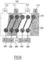
- the figure 6 illustrates a different situation in which Hall cells are placed in relation to tracks on the disc.
- the cells pass in front of a north track 120, the two tracks 111 and 121 of the group 130, then a south track 110,
- the first couple illustrated on the left is the couple [0,1] corresponding to cell 200 facing the north track 120 and cell 210 facing the singular south track 111.
- the sensor generates the sequence of bit pairs [0,1], [0,0], [1,0], [11], [0,1], etc.
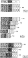
- the figure 7 shows two situations corresponding to two particular distinct moments.
- the first situation 600 describes the particular instant when each Hall cell is faced with a track of distinct singular shape.
- cell 210 has just passed north track 121 and cell 200 is still facing south track 111.
- This situation corresponds to the start of a period when the sensor generates the singular binary couple [1,0].
- the senor generates a torque [1,1].
- All the signals that we have just described can be made available to a binary data processing means, such as a processor, a microcontroller, a dedicated digital circuit or other equivalent circuit.
- this processing means interrogates the sensor at a constant time interval and thus regularly removes the information provided.
- the processing means therefore has a series 700 of binary torque that can be analyzed, as for example shown on the figure 8 .
- the speed of rotation is of the order of 20 revolutions per minute
- the processing means interrogating the angle sensor every 5 milliseconds
- the invention advantageously uses the singularity of shape of the two tracks of group 130 to detect a singularity of information (a couple [1,0]) and identify a situation where the Hall cells are facing group 130.
- Another advantage of the invention is that such a singularity of shape makes it possible to erase position defects between the Hall cells and design defects of the tracks.
- the number of successive occurrences of the same couple will depend on the speed of rotation relative to the frequency of consultation of the processing means.
- the figure 9 shows 700 series declared valid in the processing means.
- the processing means recognizes any one of the valid series, it recognizes that the means which requests the rotation of the disc (a flywheel for example) is in a known angular reference position (a reference position linked to the position of the group involved).
- the generation of the wrong torque can come from a variety of possible causes.
- a sensor according to the invention is now integrated into a more complex system, such as an automatic return system for a vehicle direction change indicator.
- the system determines whether the angle sensor must be taken into account to monitor the instant when said command must be discontinued.
- the system regularly consults and analyzes the information provided by the angle sensor to identify any singular information defined by the presence of a series of binary couples recognized as valid (identification in the reference table).
- the system knows that the steering wheel is in the upright position.
- the disc supports tracks of the electrical type.
- an aim is to constitute tracks of two varieties (for example insulating and conductive tracks) whose shape is identical.
Landscapes
- Physics & Mathematics (AREA)
- General Physics & Mathematics (AREA)
- Transmission And Conversion Of Sensor Element Output (AREA)
- Lighting Device Outwards From Vehicle And Optical Signal (AREA)
- Length Measuring Devices With Unspecified Measuring Means (AREA)
Claims (7)
- Winkelsensor für ein Fahrzeug, der einen Träger (100) umfasst, auf welchem zwei Arten von Bahnen (110; 120) ruhen, die sich im Wesentlichen radial in Bezug auf eine Drehachse des Trägers (100) erstrecken, abwechselnd um diese herum in gleichen Winkelabständen angeordnet sind und mit Detektionsmitteln (200; 210) zusammenwirken, die sich gegenüber den Bahnen (110; 120) befinden, um Informationen in Bezug auf die Rotation des Trägers (100) zu erzeugen, wobei der Sensor mindestens eine Gruppe (130) von zwei aufeinander folgenden Bahnen (111; 121) aufweist, die eine Besonderheit der Form gegenüber den anderen Bahnen (110; 120) besitzt, nämlich dass die zwei Bahnen (111; 121) der Gruppe (130) eine gemeinsame Kante (151) haben, die bezüglich der Richtung, die sie haben müsste, wenn diese zwei Bahnen nicht die Besonderheit der Form besitzen würden, um einen Winkel geneigt ist, dadurch gekennzeichnet, dass er nur zwei Detektionsmittel (200; 210) aufweist, die winkelmäßig und radial derart zueinander versetzt sind, dass sie nicht gleichzeitig irgendeine der Kanten (151) auf der Scheibe überqueren, und Verarbeitungsmittel aufweist, welche die von den Detektionsmitteln (200; 210) abgegebenen Signale empfangen und dafür ausgelegt sind, eine Situation zu identifizieren, in der sich die Detektionsmittel (200; 210) gegenüber einer Gruppe (130) befinden, die eine Besonderheit aufweist.
- Winkelsensor nach Anspruch 1, dadurch gekennzeichnet, dass die zwei Detektionsmittel (200; 210) zueinander um einen Winkel versetzt sind, der gleich einem Viertel eines Winkels ist, der zwischen einem Anfang und einem Ende einer Bahn (110; 120) definiert ist, vorausgesetzt, dass diese Letztere keine Besonderheit der Form besitzt.
- Winkelsensor nach einem der vorhergehenden Ansprüche, dadurch gekennzeichnet, dass die Bahnen (110; 120) Bahnen vom magnetischen Typ sind, wobei die erste Art einen Südpol darstellt und die zweite Art einen Nordpol darstellt, und dadurch, dass die Detektionsmittel (200; 210) Hall-Effekt-Komponenten sind.
- Winkelsensor nach einem der Ansprüche 1 bis 2, dadurch gekennzeichnet, dass die Bahnen (110; 120) Bahnen vom optischen Typ sind und die Detektionsmittel (200; 210) optische Komponenten sind.
- Winkelsensor nach einem der Ansprüche 1 bis 2, dadurch gekennzeichnet, dass die erste Art von Bahnen (110) Bahnen darstellt, die aus einem isolierenden Material bestehen, und die zweite Art Bahnen (120), die aus einem leitenden Material bestehen, und dadurch, dass die Detektionsmittel (200; 210) elektrische Komponenten vom Typ von Schleifschuhen sind.
- System, welches in einem Fahrzeug verwendet wird, dadurch gekennzeichnet, dass es einen Winkelsensor aufweist, wie durch einen der vorhergehenden Ansprüche definiert.
- System nach dem vorhergehenden Anspruch, dadurch gekennzeichnet, dass es sich um ein System zur automatischen Rückstellung eines Fahrtrichtungsanzeigers eines Fahrzeugs handelt.
Applications Claiming Priority (1)
| Application Number | Priority Date | Filing Date | Title |
|---|---|---|---|
| FR0409675A FR2875297B1 (fr) | 2004-09-13 | 2004-09-13 | Capteur d'angle intelligent pour systeme de retour automatique d'indicateur de changement de direction |
Publications (3)
| Publication Number | Publication Date |
|---|---|
| EP1635148A2 EP1635148A2 (de) | 2006-03-15 |
| EP1635148A3 EP1635148A3 (de) | 2016-06-15 |
| EP1635148B1 true EP1635148B1 (de) | 2019-12-25 |
Family
ID=34948581
Family Applications (1)
| Application Number | Title | Priority Date | Filing Date |
|---|---|---|---|
| EP05108028.1A Expired - Lifetime EP1635148B1 (de) | 2004-09-13 | 2005-09-01 | Intelligenter Winkelsensor für das automatische Rückstellungssystem eines Richtungsanzeigers |
Country Status (2)
| Country | Link |
|---|---|
| EP (1) | EP1635148B1 (de) |
| FR (1) | FR2875297B1 (de) |
Family Cites Families (7)
| Publication number | Priority date | Publication date | Assignee | Title |
|---|---|---|---|---|
| JP3677877B2 (ja) * | 1996-07-25 | 2005-08-03 | 松下電器産業株式会社 | ゲーム機用エンコーダ |
| US5898301A (en) * | 1997-04-10 | 1999-04-27 | The Torrington Company | Magnetic encoder for producing an index signal |
| FR2769088B1 (fr) * | 1997-09-26 | 1999-12-03 | Roulements Soc Nouvelle | Capteur digital de position relative |
| DE19800774B4 (de) * | 1998-01-12 | 2006-12-21 | Siemens Ag | Verfahren und magnetische Maßverkörperung zur Generierung eines Referenzsignals sowie Herstellungsverfahren für eine solche magnetische Maßverkörperung |
| JP3627531B2 (ja) * | 1998-09-30 | 2005-03-09 | セイコーエプソン株式会社 | 情報処理装置 |
| FR2811077B1 (fr) * | 2000-06-30 | 2002-09-13 | Roulements Soc Nouvelle | Dispositif de determination de la position angulaire absolue d'un organe tournant |
| SE0003169L (sv) * | 2000-09-07 | 2002-03-08 | Sem Ab | Triggivare |
-
2004
- 2004-09-13 FR FR0409675A patent/FR2875297B1/fr not_active Expired - Lifetime
-
2005
- 2005-09-01 EP EP05108028.1A patent/EP1635148B1/de not_active Expired - Lifetime
Non-Patent Citations (1)
| Title |
|---|
| None * |
Also Published As
| Publication number | Publication date |
|---|---|
| FR2875297A1 (fr) | 2006-03-17 |
| EP1635148A2 (de) | 2006-03-15 |
| EP1635148A3 (de) | 2016-06-15 |
| FR2875297B1 (fr) | 2007-02-09 |
Similar Documents
| Publication | Publication Date | Title |
|---|---|---|
| EP1882907B1 (de) | Verfahren zur Bestimmung zweier um 90 Grad phasenverschobener Signale | |
| FR2947902A1 (fr) | Capteur de position absolue et multi-periodique | |
| FR3029283A1 (fr) | Capteur d'arbre a came ou de vilebrequin pour vehicule automobile et procede de diagnostic d'un tel capteur | |
| EP1167927A1 (de) | Vorrichtung zur erfassung eines absolutenwinkelpostition | |
| FR2845154A1 (fr) | Capteur d'angle absolu comprenant un codeur a singularites non-equireparties | |
| EP1017966A1 (de) | Digitaler positionsgeber | |
| EP2430403B1 (de) | Messvorrichtung und -methode zur absolutwinkelmessung | |
| WO2000042401A2 (fr) | Procede et dispositif d'analyse d'un front d'onde a grande dynamique | |
| FR2916562A1 (fr) | Procede de detection d'un objet en mouvement dans un flux d'images | |
| EP1635148A2 (de) | Intelligenter Winkelsensor für das automatische Rückstellungssystem eines Richtungsanzeigers | |
| EP2972114B1 (de) | Kalibrierverfahren eines positionssensors in einer elektrischen synchronmaschine | |
| EP1800913A1 (de) | Vorrichtung und Verfahren zur Bestimmung der Einbaustelle eines Reifens an einem Fahrzeug | |
| WO2016034273A1 (fr) | Calculateur de vehicule | |
| EP3833985B1 (de) | Verfahren zur bestimmung einer fahrtrichtungsänderung eines fahrzeugs und zugehöriges fahrzeug | |
| WO2018086920A1 (fr) | Capteur angulaire sans contact | |
| EP1096685B1 (de) | Elektronische Vorrichtung zur Berechnung der gegenseitigen Phasenabweichung zwischen zwei abgetasteten Fehlersignalen | |
| EP1128371B1 (de) | Verfahren und Vorrichtung zur Steuerung der Position eines optischen Strahls auf einer Spur eines beweglichen Datenträgers, inbesondere eine DVD | |
| EP2997334B1 (de) | Positionskodierer | |
| EP0522926A1 (de) | Lesesystem für optische Platte | |
| EP1623874B1 (de) | Automatische Rückstelleinrichtung für einen Fahrtrichtungsanzeiger | |
| WO2009013424A2 (fr) | Procede et dispositif de determination du sens de rotation d'une roue | |
| EP2388557B1 (de) | Optischer Sensor zur Erfassung der absoluten Winkelposition unter Verwendung der Polarimetrietechnik | |
| WO2022129762A1 (fr) | Procede de surveillance d'une usure d'un actionneur | |
| EP4522998A1 (de) | Tachometer für ein flugzeugrad | |
| EP3792771A1 (de) | Programmtest |
Legal Events
| Date | Code | Title | Description |
|---|---|---|---|
| PUAI | Public reference made under article 153(3) epc to a published international application that has entered the european phase |
Free format text: ORIGINAL CODE: 0009012 |
|
| AK | Designated contracting states |
Kind code of ref document: A2 Designated state(s): AT BE BG CH CY CZ DE DK EE ES FI FR GB GR HU IE IS IT LI LT LU LV MC NL PL PT RO SE SI SK TR |
|
| AX | Request for extension of the european patent |
Extension state: AL BA HR MK YU |
|
| PUAL | Search report despatched |
Free format text: ORIGINAL CODE: 0009013 |
|
| AK | Designated contracting states |
Kind code of ref document: A3 Designated state(s): AT BE BG CH CY CZ DE DK EE ES FI FR GB GR HU IE IS IT LI LT LU LV MC NL PL PT RO SE SI SK TR |
|
| AX | Request for extension of the european patent |
Extension state: AL BA HR MK YU |
|
| RIC1 | Information provided on ipc code assigned before grant |
Ipc: G01D 5/245 20060101AFI20160506BHEP Ipc: G01D 5/14 20060101ALI20160506BHEP |
|
| STAA | Information on the status of an ep patent application or granted ep patent |
Free format text: STATUS: REQUEST FOR EXAMINATION WAS MADE |
|
| 17P | Request for examination filed |
Effective date: 20161128 |
|
| RBV | Designated contracting states (corrected) |
Designated state(s): AT BE BG CH CY CZ DE DK EE ES FI FR GB GR HU IE IS IT LI LT LU LV MC NL PL PT RO SE SI SK TR |
|
| RBV | Designated contracting states (corrected) |
Designated state(s): AT BE BG CH CY CZ DE DK EE ES FI FR GB GR HU IE IS IT LI LT LU LV MC NL PL PT RO SE SI SK TR |
|
| AKX | Designation fees paid |
Designated state(s): AT BE BG CH CY CZ DE DK EE ES FI FR GB GR HU IE IS IT LI LT LU LV MC NL PL PT RO SE SI SK TR |
|
| AXX | Extension fees paid |
Extension state: AL Extension state: YU Extension state: HR Extension state: MK Extension state: BA |
|
| STAA | Information on the status of an ep patent application or granted ep patent |
Free format text: STATUS: EXAMINATION IS IN PROGRESS |
|
| 17Q | First examination report despatched |
Effective date: 20180704 |
|
| GRAJ | Information related to disapproval of communication of intention to grant by the applicant or resumption of examination proceedings by the epo deleted |
Free format text: ORIGINAL CODE: EPIDOSDIGR1 |
|
| STAA | Information on the status of an ep patent application or granted ep patent |
Free format text: STATUS: GRANT OF PATENT IS INTENDED |
|
| GRAP | Despatch of communication of intention to grant a patent |
Free format text: ORIGINAL CODE: EPIDOSNIGR1 |
|
| INTG | Intention to grant announced |
Effective date: 20190910 |
|
| RAP1 | Party data changed (applicant data changed or rights of an application transferred) |
Owner name: SC2N |
|
| RIN1 | Information on inventor provided before grant (corrected) |
Inventor name: HALLET, MICHEL |
|
| GRAS | Grant fee paid |
Free format text: ORIGINAL CODE: EPIDOSNIGR3 |
|
| GRAA | (expected) grant |
Free format text: ORIGINAL CODE: 0009210 |
|
| STAA | Information on the status of an ep patent application or granted ep patent |
Free format text: STATUS: THE PATENT HAS BEEN GRANTED |
|
| AK | Designated contracting states |
Kind code of ref document: B1 Designated state(s): AT BE BG CH CY CZ DE DK EE ES FI FR GB GR HU IE IS IT LI LT LU LV MC NL PL PT RO SE SI SK TR |
|
| REG | Reference to a national code |
Ref country code: GB Ref legal event code: FG4D Free format text: NOT ENGLISH |
|
| REG | Reference to a national code |
Ref country code: CH Ref legal event code: EP |
|
| REG | Reference to a national code |
Ref country code: DE Ref legal event code: R096 Ref document number: 602005056500 Country of ref document: DE |
|
| REG | Reference to a national code |
Ref country code: AT Ref legal event code: REF Ref document number: 1217616 Country of ref document: AT Kind code of ref document: T Effective date: 20200115 |
|
| REG | Reference to a national code |
Ref country code: IE Ref legal event code: FG4D Free format text: LANGUAGE OF EP DOCUMENT: FRENCH |
|
| REG | Reference to a national code |
Ref country code: NL Ref legal event code: MP Effective date: 20191225 |
|
| PG25 | Lapsed in a contracting state [announced via postgrant information from national office to epo] |
Ref country code: LT Free format text: LAPSE BECAUSE OF FAILURE TO SUBMIT A TRANSLATION OF THE DESCRIPTION OR TO PAY THE FEE WITHIN THE PRESCRIBED TIME-LIMIT Effective date: 20191225 Ref country code: GR Free format text: LAPSE BECAUSE OF FAILURE TO SUBMIT A TRANSLATION OF THE DESCRIPTION OR TO PAY THE FEE WITHIN THE PRESCRIBED TIME-LIMIT Effective date: 20200326 Ref country code: BG Free format text: LAPSE BECAUSE OF FAILURE TO SUBMIT A TRANSLATION OF THE DESCRIPTION OR TO PAY THE FEE WITHIN THE PRESCRIBED TIME-LIMIT Effective date: 20200325 Ref country code: FI Free format text: LAPSE BECAUSE OF FAILURE TO SUBMIT A TRANSLATION OF THE DESCRIPTION OR TO PAY THE FEE WITHIN THE PRESCRIBED TIME-LIMIT Effective date: 20191225 Ref country code: LV Free format text: LAPSE BECAUSE OF FAILURE TO SUBMIT A TRANSLATION OF THE DESCRIPTION OR TO PAY THE FEE WITHIN THE PRESCRIBED TIME-LIMIT Effective date: 20191225 Ref country code: SE Free format text: LAPSE BECAUSE OF FAILURE TO SUBMIT A TRANSLATION OF THE DESCRIPTION OR TO PAY THE FEE WITHIN THE PRESCRIBED TIME-LIMIT Effective date: 20191225 |
|
| REG | Reference to a national code |
Ref country code: LT Ref legal event code: MG4D |
|
| PG25 | Lapsed in a contracting state [announced via postgrant information from national office to epo] |
Ref country code: NL Free format text: LAPSE BECAUSE OF FAILURE TO SUBMIT A TRANSLATION OF THE DESCRIPTION OR TO PAY THE FEE WITHIN THE PRESCRIBED TIME-LIMIT Effective date: 20191225 Ref country code: PT Free format text: LAPSE BECAUSE OF FAILURE TO SUBMIT A TRANSLATION OF THE DESCRIPTION OR TO PAY THE FEE WITHIN THE PRESCRIBED TIME-LIMIT Effective date: 20200520 Ref country code: CZ Free format text: LAPSE BECAUSE OF FAILURE TO SUBMIT A TRANSLATION OF THE DESCRIPTION OR TO PAY THE FEE WITHIN THE PRESCRIBED TIME-LIMIT Effective date: 20191225 Ref country code: RO Free format text: LAPSE BECAUSE OF FAILURE TO SUBMIT A TRANSLATION OF THE DESCRIPTION OR TO PAY THE FEE WITHIN THE PRESCRIBED TIME-LIMIT Effective date: 20191225 Ref country code: EE Free format text: LAPSE BECAUSE OF FAILURE TO SUBMIT A TRANSLATION OF THE DESCRIPTION OR TO PAY THE FEE WITHIN THE PRESCRIBED TIME-LIMIT Effective date: 20191225 |
|
| PG25 | Lapsed in a contracting state [announced via postgrant information from national office to epo] |
Ref country code: SK Free format text: LAPSE BECAUSE OF FAILURE TO SUBMIT A TRANSLATION OF THE DESCRIPTION OR TO PAY THE FEE WITHIN THE PRESCRIBED TIME-LIMIT Effective date: 20191225 Ref country code: IS Free format text: LAPSE BECAUSE OF FAILURE TO SUBMIT A TRANSLATION OF THE DESCRIPTION OR TO PAY THE FEE WITHIN THE PRESCRIBED TIME-LIMIT Effective date: 20200425 |
|
| REG | Reference to a national code |
Ref country code: DE Ref legal event code: R097 Ref document number: 602005056500 Country of ref document: DE |
|
| PG25 | Lapsed in a contracting state [announced via postgrant information from national office to epo] |
Ref country code: ES Free format text: LAPSE BECAUSE OF FAILURE TO SUBMIT A TRANSLATION OF THE DESCRIPTION OR TO PAY THE FEE WITHIN THE PRESCRIBED TIME-LIMIT Effective date: 20191225 Ref country code: DK Free format text: LAPSE BECAUSE OF FAILURE TO SUBMIT A TRANSLATION OF THE DESCRIPTION OR TO PAY THE FEE WITHIN THE PRESCRIBED TIME-LIMIT Effective date: 20191225 |
|
| PLBE | No opposition filed within time limit |
Free format text: ORIGINAL CODE: 0009261 |
|
| STAA | Information on the status of an ep patent application or granted ep patent |
Free format text: STATUS: NO OPPOSITION FILED WITHIN TIME LIMIT |
|
| REG | Reference to a national code |
Ref country code: AT Ref legal event code: MK05 Ref document number: 1217616 Country of ref document: AT Kind code of ref document: T Effective date: 20191225 |
|
| PG25 | Lapsed in a contracting state [announced via postgrant information from national office to epo] |
Ref country code: SI Free format text: LAPSE BECAUSE OF FAILURE TO SUBMIT A TRANSLATION OF THE DESCRIPTION OR TO PAY THE FEE WITHIN THE PRESCRIBED TIME-LIMIT Effective date: 20191225 |
|
| 26N | No opposition filed |
Effective date: 20200928 |
|
| PG25 | Lapsed in a contracting state [announced via postgrant information from national office to epo] |
Ref country code: AT Free format text: LAPSE BECAUSE OF FAILURE TO SUBMIT A TRANSLATION OF THE DESCRIPTION OR TO PAY THE FEE WITHIN THE PRESCRIBED TIME-LIMIT Effective date: 20191225 Ref country code: IT Free format text: LAPSE BECAUSE OF FAILURE TO SUBMIT A TRANSLATION OF THE DESCRIPTION OR TO PAY THE FEE WITHIN THE PRESCRIBED TIME-LIMIT Effective date: 20191225 |
|
| PG25 | Lapsed in a contracting state [announced via postgrant information from national office to epo] |
Ref country code: PL Free format text: LAPSE BECAUSE OF FAILURE TO SUBMIT A TRANSLATION OF THE DESCRIPTION OR TO PAY THE FEE WITHIN THE PRESCRIBED TIME-LIMIT Effective date: 20191225 |
|
| PG25 | Lapsed in a contracting state [announced via postgrant information from national office to epo] |
Ref country code: MC Free format text: LAPSE BECAUSE OF FAILURE TO SUBMIT A TRANSLATION OF THE DESCRIPTION OR TO PAY THE FEE WITHIN THE PRESCRIBED TIME-LIMIT Effective date: 20191225 |
|
| REG | Reference to a national code |
Ref country code: CH Ref legal event code: PL |
|
| GBPC | Gb: european patent ceased through non-payment of renewal fee |
Effective date: 20200901 |
|
| REG | Reference to a national code |
Ref country code: BE Ref legal event code: MM Effective date: 20200930 |
|
| PG25 | Lapsed in a contracting state [announced via postgrant information from national office to epo] |
Ref country code: LU Free format text: LAPSE BECAUSE OF NON-PAYMENT OF DUE FEES Effective date: 20200901 |
|
| PG25 | Lapsed in a contracting state [announced via postgrant information from national office to epo] |
Ref country code: CH Free format text: LAPSE BECAUSE OF NON-PAYMENT OF DUE FEES Effective date: 20200930 Ref country code: BE Free format text: LAPSE BECAUSE OF NON-PAYMENT OF DUE FEES Effective date: 20200930 Ref country code: LI Free format text: LAPSE BECAUSE OF NON-PAYMENT OF DUE FEES Effective date: 20200930 Ref country code: IE Free format text: LAPSE BECAUSE OF NON-PAYMENT OF DUE FEES Effective date: 20200901 Ref country code: GB Free format text: LAPSE BECAUSE OF NON-PAYMENT OF DUE FEES Effective date: 20200901 |
|
| PG25 | Lapsed in a contracting state [announced via postgrant information from national office to epo] |
Ref country code: TR Free format text: LAPSE BECAUSE OF FAILURE TO SUBMIT A TRANSLATION OF THE DESCRIPTION OR TO PAY THE FEE WITHIN THE PRESCRIBED TIME-LIMIT Effective date: 20191225 Ref country code: CY Free format text: LAPSE BECAUSE OF FAILURE TO SUBMIT A TRANSLATION OF THE DESCRIPTION OR TO PAY THE FEE WITHIN THE PRESCRIBED TIME-LIMIT Effective date: 20191225 |
|
| P01 | Opt-out of the competence of the unified patent court (upc) registered |
Effective date: 20230528 |
|
| PGFP | Annual fee paid to national office [announced via postgrant information from national office to epo] |
Ref country code: FR Payment date: 20230927 Year of fee payment: 19 Ref country code: DE Payment date: 20230911 Year of fee payment: 19 |
|
| REG | Reference to a national code |
Ref country code: DE Ref legal event code: R119 Ref document number: 602005056500 Country of ref document: DE |
|
| PG25 | Lapsed in a contracting state [announced via postgrant information from national office to epo] |
Ref country code: DE Free format text: LAPSE BECAUSE OF NON-PAYMENT OF DUE FEES Effective date: 20250401 |
|
| PG25 | Lapsed in a contracting state [announced via postgrant information from national office to epo] |
Ref country code: FR Free format text: LAPSE BECAUSE OF NON-PAYMENT OF DUE FEES Effective date: 20240930 |