EP1635108B1 - Method and apparatus to detect an object - Google Patents
Method and apparatus to detect an object Download PDFInfo
- Publication number
- EP1635108B1 EP1635108B1 EP05014657A EP05014657A EP1635108B1 EP 1635108 B1 EP1635108 B1 EP 1635108B1 EP 05014657 A EP05014657 A EP 05014657A EP 05014657 A EP05014657 A EP 05014657A EP 1635108 B1 EP1635108 B1 EP 1635108B1
- Authority
- EP
- European Patent Office
- Prior art keywords
- sensor
- evaluation unit
- sensors
- coordinate points
- flagged
- Prior art date
- Legal status (The legal status is an assumption and is not a legal conclusion. Google has not performed a legal analysis and makes no representation as to the accuracy of the status listed.)
- Active
Links
- 238000000034 method Methods 0.000 title claims abstract description 21
- 238000011156 evaluation Methods 0.000 claims abstract description 51
- 238000012544 monitoring process Methods 0.000 claims description 19
- 230000001960 triggered effect Effects 0.000 claims description 11
- 230000000007 visual effect Effects 0.000 claims description 3
- 230000005540 biological transmission Effects 0.000 claims 2
- 238000001514 detection method Methods 0.000 description 5
- 238000005259 measurement Methods 0.000 description 5
- 238000012806 monitoring device Methods 0.000 description 5
- 230000008901 benefit Effects 0.000 description 4
- 230000001681 protective effect Effects 0.000 description 3
- 230000009466 transformation Effects 0.000 description 3
- 238000004519 manufacturing process Methods 0.000 description 2
- 230000035515 penetration Effects 0.000 description 2
- 230000009471 action Effects 0.000 description 1
- 238000006243 chemical reaction Methods 0.000 description 1
- 239000003086 colorant Substances 0.000 description 1
- 230000000694 effects Effects 0.000 description 1
- 238000002372 labelling Methods 0.000 description 1
- 230000000149 penetrating effect Effects 0.000 description 1
- 230000008569 process Effects 0.000 description 1
- 238000012545 processing Methods 0.000 description 1
- 230000005855 radiation Effects 0.000 description 1
- 230000035484 reaction time Effects 0.000 description 1
- 230000009467 reduction Effects 0.000 description 1
- 238000000844 transformation Methods 0.000 description 1
Images


Classifications
-
- F—MECHANICAL ENGINEERING; LIGHTING; HEATING; WEAPONS; BLASTING
- F16—ENGINEERING ELEMENTS AND UNITS; GENERAL MEASURES FOR PRODUCING AND MAINTAINING EFFECTIVE FUNCTIONING OF MACHINES OR INSTALLATIONS; THERMAL INSULATION IN GENERAL
- F16P—SAFETY DEVICES IN GENERAL; SAFETY DEVICES FOR PRESSES
- F16P3/00—Safety devices acting in conjunction with the control or operation of a machine; Control arrangements requiring the simultaneous use of two or more parts of the body
- F16P3/12—Safety devices acting in conjunction with the control or operation of a machine; Control arrangements requiring the simultaneous use of two or more parts of the body with means, e.g. feelers, which in case of the presence of a body part of a person in or near the danger zone influence the control or operation of the machine
- F16P3/14—Safety devices acting in conjunction with the control or operation of a machine; Control arrangements requiring the simultaneous use of two or more parts of the body with means, e.g. feelers, which in case of the presence of a body part of a person in or near the danger zone influence the control or operation of the machine the means being photocells or other devices sensitive without mechanical contact
- F16P3/147—Safety devices acting in conjunction with the control or operation of a machine; Control arrangements requiring the simultaneous use of two or more parts of the body with means, e.g. feelers, which in case of the presence of a body part of a person in or near the danger zone influence the control or operation of the machine the means being photocells or other devices sensitive without mechanical contact using electro-magnetic technology, e.g. tags or radar
-
- F—MECHANICAL ENGINEERING; LIGHTING; HEATING; WEAPONS; BLASTING
- F16—ENGINEERING ELEMENTS AND UNITS; GENERAL MEASURES FOR PRODUCING AND MAINTAINING EFFECTIVE FUNCTIONING OF MACHINES OR INSTALLATIONS; THERMAL INSULATION IN GENERAL
- F16P—SAFETY DEVICES IN GENERAL; SAFETY DEVICES FOR PRESSES
- F16P3/00—Safety devices acting in conjunction with the control or operation of a machine; Control arrangements requiring the simultaneous use of two or more parts of the body
- F16P3/12—Safety devices acting in conjunction with the control or operation of a machine; Control arrangements requiring the simultaneous use of two or more parts of the body with means, e.g. feelers, which in case of the presence of a body part of a person in or near the danger zone influence the control or operation of the machine
- F16P3/14—Safety devices acting in conjunction with the control or operation of a machine; Control arrangements requiring the simultaneous use of two or more parts of the body with means, e.g. feelers, which in case of the presence of a body part of a person in or near the danger zone influence the control or operation of the machine the means being photocells or other devices sensitive without mechanical contact
- F16P3/144—Safety devices acting in conjunction with the control or operation of a machine; Control arrangements requiring the simultaneous use of two or more parts of the body with means, e.g. feelers, which in case of the presence of a body part of a person in or near the danger zone influence the control or operation of the machine the means being photocells or other devices sensitive without mechanical contact using light grids
Definitions
- the present invention relates to a method for detecting an object within a surveillance area, in which at least two sensors each monitor at least part of the surveillance area. Furthermore, the invention is directed to an apparatus for use in such a method. Such a method and such a device are made, for example DE-A-19709799 known.
- Methods of this kind are used in particular in safety engineering.
- it is continuously checked whether an object detected within the monitoring area, in particular a person, enters the danger zone of a machine operating within the surveillance area, for example a robot. If such an intrusion is detected, the machine may be shut down or another suitable safety function may be triggered.
- a separate protective field is usually defined for each sensor, with which the area between sensor and machine is monitored for the penetration of an object.
- the measurement data of each sensor are each supplied separately to an evaluation unit which, for example, shuts off the machine if, due to the measurement data supplied by a sensor, a violation of the protected area is detected by a comparison with predetermined desired data. Since the measurement data of the sensors are usually determined in each case in its own reference system and transmitted to the evaluation, they must be performed before the implementation of the Comparisons are transformed by the evaluation unit according to the arrangement of the sensor and the data format used in the reference system of the evaluation.
- a protection zone violation reported by a sensor does not necessarily mean that the detected object also violates the danger zone of the machine. Since the sensor can not see the area between the object and the machine, it can not be distinguished whether the object with its part remote from the sensor extends into the danger zone of the machine or not. For safety reasons, therefore, the machine must be switched off when detecting an object, even if in fact there is no violation of the danger zone of the machine. The detection of the object is thus incomplete with regard to its actual shape, since the "shadow" of the object lying between the object and the machine as seen by the sensor must also be taken into account in the object detection.
- the computing time required in the evaluation unit for the required coordinate transformations is relatively high, so that high computing power is required, especially when using multiple sensors for time-critical application.
- the present invention is therefore based on the object, a method and an apparatus of the type mentioned in such a way that a more accurate detection of objects is possible.
- each sensor generates a digital single image of the entire monitoring area, wherein the individual images of all sensors are generated in a uniform coordinate system, that of each sensor those coordinate points of the generated by him Single image are marked as "safe” that he recognizes as free from the object that all other coordinate points of the individual images are marked as "uncertain”, that the individual images thus generated are each transferred to an evaluation that the individual images transmitted by the evaluation according to their Coordinate common system are superimposed on a resulting overall image by those coordinate points of the entire image as "safe” are marked, at least in one of the transmitted from the sensors individual images as "safe” gekennz are calibrated, while all other coordinate points of the overall image are marked as "uncertain”, and that the coordinate points marked "uncertain” in the overall image are used to determine the object coordinates.
- each sensor is designed to generate a digital single image of the entire surveillance area in a coordinate system which is uniform for all sensors and to mark those coordinate points of the individual images generated by it as "safe ", which he recognizes as free from the object that each sensor with an evaluation unit for transmitting the is connected to such generated individual images, that the evaluation unit is designed to superimpose the transmitted individual images according to their common coordinate system to form a resulting overall image, wherein those coordinate points of the overall image by the evaluation as "safe” kenn Schweizerbar, at least in one of the transmitted from the sensors individual images are marked as "safe", while all other coordinate points of the overall image are identifiable as "uncertain”, and that the evaluation unit is designed to determine the object coordinates from the coordinate points identified as "unsafe” in the overall image.
- the "shadow area" of the object can be reliably recognized as such during detection of an object and thus classified as "safe” as long as at least one sensor can view this shadow area. Only the space actually occupied by the object of the surveillance area is accordingly classified as "unsafe", so that an optimal and in particular minimized detection of the object within the surveillance area is ensured.
- a further advantage of the invention is that the generation of the individual images for all sensors takes place in a uniform coordinate system, in that either all sensors operate from the outset in the same coordinate system or the required transformation into the uniform coordinate system is performed by each sensor itself.
- the load of the evaluation unit can be significantly reduced, so that the resulting process speed can be increased.
- the labeling as a safe or unsafe area already at the level of the sensors causes a corresponding relief of the evaluation.
- the resulting overall image is superimposed with a defined by the evaluation, in particular dynamically changing danger area and a safety-related function triggered when at least a predetermined number of marked as unsafe coordinate points is determined within the danger area.
- a safety-related function triggered when at least a predetermined number of marked as unsafe coordinate points is determined within the danger area.
- an evaluation of the object recognition is possible with respect to a predetermined danger area, as defined for example in safety technology in dangerous machines.
- the safety-relevant function can already be triggered when determining a single insecure coordinate point or only at several such points within the danger zone.
- the danger area may be, for example, the area of action of a machine, in particular a robot, while the object to be detected is formed by a person who is located within the surveillance area and must be protected from dangerous contact with the robot.
- a safety-relevant function such as a shutdown of the machine is only triggered when the detected object actually penetrates into the danger zone of the machine. If an object is detected by a sensor within the monitoring area in such a way that the "shadow" of the object, which is not visible to the sensor, comes to rest between the object and the machine, the safety-relevant function is not triggered according to the invention, as long as At least one of the sensors can see this shadow area and thus classify the coordinate points of this area as "safe".
- the individual images of the various sensors each have the same resolution (discretization).
- the superimposition of the images in the evaluation unit can be accelerated since further conversion within the evaluation unit is not required.
- the computational effort in the processing of images can thus be reduced, so that the size of the required danger area can be minimized, since a shorter reaction time is achieved when triggering the safety-related function.
- this can be achieved by increasing the sphere of activity of the machine.
- the common monitoring area is defined for each sensor in an initialization phase, and the own position relative to the monitored area is defined.
- This initialization phase guarantees a uniform reference system of all sensors as well as a uniform format of the sensor data to be sent to the evaluation unit.
- the values assigned to each coordinate point of the individual images are "safely” and “uncertainly” coded binary by each sensor and the correspondingly coded sensor data is transmitted to the evaluation unit.
- the binary coding minimizes the amount of data to be transmitted by the sensors to the evaluation unit.
- the individual images are generated by the sensors in a Cartesian coordinate system and transmitted to the evaluation unit, wherein in particular the resolution (discretization) in the x and y directions is the same.
- a Cartesian coordinate system has the advantage over a polar coordinate system that no point in space is particularly preferred. In particular, when using different sensors with different locations therefore a direct comparison of all coordinate points of different individual images is possible.
- the invention can be applied to three-dimensional image acquisition.
- three-dimensional image acquisition is advantageous when the machine is operating at different heights.
- a person can move without danger in the area below the robot arm. Only when the robot arm is lowered in the direction of the person, a corresponding safety-relevant function must be triggered.
- the use of sensors with three-dimensional resolution and a corresponding three-dimensional generation and evaluation of the individual and total images is required. The same applies to a corresponding variable three-dimensional embodiment of the detected object.
- the evaluation unit in particular classifies the objects detected in the monitoring area into objects belonging to the machine and not belonging to the machine. This is required if the machine is arranged so that it is also detected by the sensors. Since the machine is by definition always located within the danger zone, without the specified classification, self-triggering of the safety-relevant functions by the machine would take place. For example, machine position data obtained directly from the machine control can be compared with the position data acquired by the sensor, so that the specified classification can be achieved in this way. The detected "object data" belonging to the machine can then be disregarded when checking the danger area.
- a use of an infrared sensor is possible, which only reacts to the heat radiation of people.
- a classification is unnecessary if the machine is arranged so that it can not be detected by the sensor at least within the monitoring area. This can be achieved, for example, by using an area sensor arranged such that the working area of the machine is outside the scanning area of the area sensor. Of course, the area sensor must continue to be arranged so that objects entering the surveillance area are reliably detected.
- the slowing down and / or the stopping of the machine is defined as one of the safety-relevant functions.
- maximum safety is achieved if the machine is stopped as quickly as possible when an object enters the danger zone. In some cases, however, slowing down the speed of movement of the machine may be sufficient.
- the evaluation unit has information about the movement of the object and / or machine, then either a reduction is possible the speed of movement or the complete stop of the machine are selected. Compared to a stop-only programmed machine, this has the advantage that a machine stop is really only triggered in necessary cases, while in less urgent cases slowing the machine movement is sufficient. This ensures that the manufacturing process is not unnecessarily hindered.
- the deflection of the machine relative to the object can be defined. Dodging the machine can often be safer than slowing down or stopping the machine because, due to the inertia of the machine, stopping may be less readily achieved than an evasive movement. For this, however, it is necessary that information about the direction of movement and speed of movement of the object are known, so that the evasive movement takes place in the right direction. In addition, this also ensures that the manufacturing process is not interrupted unnecessarily.
- the triggering of an acoustic and / or visual warning signal is defined as one of the safety-relevant functions.
- This has the particular advantage that the operation of the machine is not interrupted and at the same time an effective warning against invading objects, especially people, is issued.
- Particularly advantageous is a combination of the warning signal with one or more of the above-mentioned safety-related functions.
- danger areas of different degrees can be defined. If an object penetrates into a first-degree range, ie a relatively low hazard, an acoustic or visual warning signal is triggered, which does not yet trigger interrupts the work flow of the machine. However, if the object penetrates into the danger zone of the second degree, the machine either deviates from the object or is slowed down in its movement and possibly stopped completely.
- FIG. 1 shows a monitoring device 1 according to the prior art, with surface sensors 2, 3 designed as laser scanners, which are each connected via lines 4, 5 to an evaluation unit 6.
- the evaluation unit 6 is connected via a further line 7 to a machine control 8 of a robot 9 designed as a robot, which comprises a movable robot arm 10. Via the line 7, a safety-relevant function of the machine control 8 can be triggered by the evaluation unit 6, for example the machine 9 can be switched off.
- the movement of the robot arm 10 defines a danger zone 11, which is monitored by the sensors 2, 3.
- the danger zone 11 penetrating objects can by the movements of the robot arm 10 be endangered, so that such an intrusion, for example, must lead to a shutdown of the machine 9 through the evaluation unit 6.
- FIG. 1 both an object 12, which does not violate the danger zone 11, and an object 12 ', which violates the danger zone 11, are depicted.
- a protective area 13, 14 is defined for each sensor 2, 3, which together form a monitoring area 15 of the monitoring device 1.
- the protection areas 13, 14 are thereby scanned by scanning beams 16, 17, which are emitted by the sensors 2, 3, wherein in Fig. 1 only the two protection areas 13, 14 limiting scanning beams 16 and 17 (edge beams) are located.
- the protection areas 13, 14 are limited except by the marginal rays 16, 17 by lying in the scanning range of the sensors 2, 3 edges 18, 19 of the danger zone 11.
- the distance values are stored as nominal values in the uncritical case, ie in the case where no object 12 is arranged within one of the protection areas 13, 14.
- the evaluation unit 6 compares the measured values supplied by the sensors 2, 3 with the respective stored setpoint values and triggers a safety-relevant function via the machine controller 8, for example switching off the machine 9, if one of the measured values is smaller than the corresponding setpoint value, as it does upon penetration of the object 12 'into the protection area 13.
- the object 12 also triggers a corresponding safety-relevant signal, since the protected area 14 of the sensor 3 is damaged by the object 12, although the object 12 does not penetrate into the danger area 11. Since the area 20 lying within the protection area 14 between the object 12 and the danger area 11 forms a shading, it can not be seen by the sensor 3, so that the machine 9 has to be switched off in order to maintain the required safety.
- the object 12 is in a monitoring area 21, which is monitored by the sensors 2, 3.
- the scanning angles of the sensors 2, 3 are not limited to the danger zone 11, but rather the scanning beams 16, 17 of the sensors 2, 3 cover substantially larger, overlapping scanning areas 22, 23 which comprise the danger zone 11 ,
- each sensor 2, 3 is capable of a transformation between its own for each coordinate point in the monitoring area 21 Measuring coordinates and a uniform, comprehensive coordinate system for all sensors 2, 3 perform.
- each sensor 2, 3 is thus able to transform the measurement data determined in its own coordinate system directly into the common coordinate system common to all sensors 2, 3.
- Each of the sensors 2, 3 generates with each sample, i. with each sweep of its scan area 22, 23, a single digital image 24, 25 of the entire monitor area 21, as shown in Figs. 3a) and 3b).
- all of the respective sensor 2, 3 during a scan as freely recognized coordinate points of the common coordinate system are marked as "safe”, while all remaining coordinate points are marked as "uncertain”.
- These coordinate points identified as "uncertain” are thus both coordinate points of the monitoring area 21, at which an object 12 is actually present, as well as coordinate points which are not visible to the respective sensor 2, 3 and thus for the respective Sensor 2, 3 are in the "shadow" of the object 12.
- Fig. 3a the corresponding generated by the sensor 2 single image 24 is shown.
- the sensor 2 is also shown in Fig. 3a) for clarity.
- the individual image 24 comprises a "safe" area 27 shown in white, which contains the coordinate points marked as "safe” by the sensor 2. Representing all "safe" coordinate points in Fig. 3 a) a coordinate point 28 is highlighted.
- the individual image 24 comprises two hatched areas 29, 30, each of which comprises the sensor 2 marked as "uncertain" coordinate points.
- insecure coordinate points identify either the position of an object 12 detected in the monitoring area 21 or areas which are not visible to the sensor 2.
- a precarious coordinate point 32 is shown as representative in Fig. 3a), which coincides with the position of the dashed line indicated object 12, while another coordinate point 33 is marked as uncertain, since it is for the sensor 2 in the "shadow" of the object 12 and therefore not visible.
- the area 30 can not be viewed by the sensor 2 because it lies outside its scanning area 22, so that the coordinate points 34 located in the area 30 are also marked as unsafe.
- FIG. 3 b shows a white "safe" area 35 with safe coordinate points 36 as well as three shaded unsafe areas 37, 38, 39 with unsigned coordinate points 40, 41, 42 includes.
- the individual images 24, 25 marked in this way are transmitted by the sensors 2, 3 to the evaluation unit 6, which superimposes the individual images 24, 25 corresponding to the common coordinate system into a resulting overall image 43, which is shown in FIG. 3c) is.
- those coordinate points of the overall image 43 are marked as safe, which are marked as safe at least in one of the individual images 24, 25 transmitted by the sensors 2, 3, while all other coordinate points of the overall image 43 are identified as uncertain.
- the object 12 without "shadows" is detected in its correct form in an unsafe area 44 shown hatched by the coordinate points marked as uncertain.
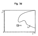
- the generated overall image 43 is superimposed by the evaluation unit 6 with the danger area 11 (see FIG. 3d)) and checks whether within the hazard area 11 a predetermined minimum number of coordinate points marked as unsafe is contained, i. there is an overlap of the insecure area 44 with the danger area 11.
- the danger zone 11 is advantageously also present in the same coordinate system as the individual images 24, 25 and the overall image 43 in order to allow a simple overlay with the overall image 43 in this way. Only if a predetermined minimum overlap of uncertain coordinate points of the overall image 43 and danger zone 11 is present, the evaluation unit 6 triggers a corresponding safety-relevant function, for example a shutdown of the machine 9.
- the illustration of FIG. 3d) can be displayed on a display unit for monitoring by a supervisor.
- the safe and the uncertain coordinate points or areas defined by them on the display unit are advantageously displayed in different colors.
- the danger zone can also be highlighted in color so that the monitoring person can immediately recognize when there is a violation of the danger zone or, for example, is imminent.
Abstract
Description
Die vorliegende Erfindung betrifft ein Verfahren zum Erfassen eines Objekts innerhalb eines Überwachungsbereichs, bei dem zumindest zwei Sensoren jeweils mindestens einen Teil des Überwachungsbereichs überwachen. Weiterhin ist die Erfindung auf eine Vorrichtung zur Verwendung bei einem solchen Verfahren gerichtet. Ein derartiges Verfahren und eine derartige Vorrichtung sind z.B. aus
Verfahren dieser Art werden insbesondere in der Sicherheitstechnik verwendet. Dabei wird beispielsweise fortlaufend geprüft, ob ein innerhalb des Überwachungsbereichs erfasstes Objekt, insbesondere eine Person, in den Gefahrenbereich einer innerhalb des Überwachungsbereichs arbeitenden Maschine, beispielsweise eines Roboters, eindringt. Wird ein solches Eindringen festgestellt, kann die Maschine abgeschaltet oder eine sonstige geeignete Sicherheitsfunktion ausgelöst werden.Methods of this kind are used in particular in safety engineering. In this case, for example, it is continuously checked whether an object detected within the monitoring area, in particular a person, enters the danger zone of a machine operating within the surveillance area, for example a robot. If such an intrusion is detected, the machine may be shut down or another suitable safety function may be triggered.
Bei der Verwendung von als Flächensensoren ausgebildeten Laserscannern ist dabei üblicherweise für jeden Sensor ein eigenes Schutzfeld definiert, mit dem der Bereich zwischen Sensor und Maschine auf Eindringen eines Objekts überwacht wird. Die Messdaten jedes Sensors werden jeweils separat einer Auswerteeinheit zugeführt, die beispielsweise die Maschine abschaltet, wenn aufgrund der von einem Sensor gelieferten Messdaten durch einen Vergleich mit vorgegebenen Solldaten eine Verletzung des Schutzbereichs erkannt wird. Da die Messdaten der Sensoren üblicherweise jeweils in dessen eigenem Bezugssystem ermittelt und an die Auswerteeinheit übertragen werden, müssen diese vor Durchführung des Vergleichs von der Auswerteeinheit entsprechend der Anordnung des Sensors und dem verwendeten Datenformat in das Bezugssystem der Auswerteeinheit transformiert werden.When using laser scanners designed as surface sensors, a separate protective field is usually defined for each sensor, with which the area between sensor and machine is monitored for the penetration of an object. The measurement data of each sensor are each supplied separately to an evaluation unit which, for example, shuts off the machine if, due to the measurement data supplied by a sensor, a violation of the protected area is detected by a comparison with predetermined desired data. Since the measurement data of the sensors are usually determined in each case in its own reference system and transmitted to the evaluation, they must be performed before the implementation of the Comparisons are transformed by the evaluation unit according to the arrangement of the sensor and the data format used in the reference system of the evaluation.
Problematisch ist dabei, dass eine von einem Sensor gemeldete Schutzbereichsverletzung nicht notwendigerweise bedeutet, dass das erfasste Objekt auch den Gefahrenbereich der Maschine verletzt. Da der Sensor den zwischen dem Objekt und der Maschine gelegenen Bereich nicht einsehen kann, kann nicht unterschieden werden, ob das Objekt mit seinem vom Sensor abgelegenen Teil bis in den Gefahrenbereich der Maschine reicht oder nicht. Aus Sicherheitsgründen muss daher beim Erfassen eines Objekts die Maschine abgeschaltet werden, auch wenn tatsächlich gar keine Verletzung des Gefahrenbereichs der Maschine vorliegt. Die Erfassung des Objekts ist somit betreffend seine tatsächliche Form unvollständig, da auch der zwischen dem Objekt und der Maschine aus Sicht des Sensors liegende "Schatten" des Objekts bei der Objekterfassung berücksichtigt werden muss.The problem with this is that a protection zone violation reported by a sensor does not necessarily mean that the detected object also violates the danger zone of the machine. Since the sensor can not see the area between the object and the machine, it can not be distinguished whether the object with its part remote from the sensor extends into the danger zone of the machine or not. For safety reasons, therefore, the machine must be switched off when detecting an object, even if in fact there is no violation of the danger zone of the machine. The detection of the object is thus incomplete with regard to its actual shape, since the "shadow" of the object lying between the object and the machine as seen by the sensor must also be taken into account in the object detection.
Weiterhin ist es nachteilig, dass aufgrund des beschriebenen Schattenwurfs des Schutzbereichs der Sensoren immer bis zum Sensor definiert sein muss, so dass eine freie Definition des Schutzbereichs innerhalb des Überwachungsraums nicht möglich ist.Furthermore, it is disadvantageous that due to the described shadowing of the protected area of the sensors must always be defined to the sensor, so that a free definition of the protected area within the interstitial space is not possible.
Letztlich ist der Rechenzeitaufwand in der Auswerteeinheit für die erforderlichen Koordinatentransformationen relativ hoch, so dass insbesondere bei der Verwendung von mehreren Sensoren für zeitkritische Anwendung hohe Rechenleistungen erforderlich sind.Ultimately, the computing time required in the evaluation unit for the required coordinate transformations is relatively high, so that high computing power is required, especially when using multiple sensors for time-critical application.
Der vorliegenden Erfindung liegt daher die Aufgabe zugrunde, ein Verfahren und eine Vorrichtung der eingangs genannten Art so auszubilden, dass eine genauere Erfassung von Objekten möglich ist.The present invention is therefore based on the object, a method and an apparatus of the type mentioned in such a way that a more accurate detection of objects is possible.
Die das Verfahren betreffende Aufgabe wird ausgehend von einem Verfahren der eingangs genannten Art dadurch gelöst, dass jeder Sensor ein digitales Einzelabbild des gesamten Überwachungsbereichs erzeugt, wobei die Einzelabbilder aller Sensoren in einem einheitlichen Koordinatensystem erzeugt werden, dass von jedem Sensor diejenigen Koordinatenpunkte des von ihm erzeugten Einzelabbildes als "sicher" gekennzeichnet werden, die er als frei vom Objekt erkennt, dass alle anderen Koordinatenpunkte der Einzelabbilder als "unsicher" gekennzeichnet werden, dass die derart erzeugten Einzelabbilder jeweils zu einer Auswerteeinheit übertragen werden, dass die übertragenen Einzelabbilder von der Auswerteeinheit entsprechend ihrem gemeinsamen Koordinatensystem zu einem resultierenden Gesamtabbild überlagert werden, indem diejenigen Koordinatenpunkte des Gesamtabbilds als "sicher" gekennzeichnet werden, die zumindest in einem der von den Sensoren übertragenen Einzelabbilder als "sicher" gekennzeichnet sind, während alle anderen Koordinatenpunkte des Gesamtabbilds als "unsicher" gekennzeichnet werden, und dass die im Gesamtabbild als "unsicher" gekennzeichneten Koordinatenpunkte zur Bestimmung der Objektkoordinaten verwendet werden.The object relating to the method is achieved on the basis of a method of the type mentioned above in that each sensor generates a digital single image of the entire monitoring area, wherein the individual images of all sensors are generated in a uniform coordinate system, that of each sensor those coordinate points of the generated by him Single image are marked as "safe" that he recognizes as free from the object that all other coordinate points of the individual images are marked as "uncertain", that the individual images thus generated are each transferred to an evaluation that the individual images transmitted by the evaluation according to their Coordinate common system are superimposed on a resulting overall image by those coordinate points of the entire image as "safe" are marked, at least in one of the transmitted from the sensors individual images as "safe" gekennz are calibrated, while all other coordinate points of the overall image are marked as "uncertain", and that the coordinate points marked "uncertain" in the overall image are used to determine the object coordinates.
Die die Vorrichtung betreffende Aufgabe wird ausgehend von einer Vorrichtung der eingangs genannten Art dadurch gelöst, dass jeder Sensor ausgebildet ist zur Erzeugung eines digitalen Einzelabbildes des gesamten Überwachungsbereichs in einem für alle Sensoren einheitlichen Koordinatensystem und zur Kennzeichnung derjenigen Koordinatenpunkte der von ihm erzeugten Einzelabbilder als "sicher", die er als frei von dem Objekt erkennt, dass jeder Sensor mit einer Auswerteeinheit zur Übertragung der derart erzeugten Einzelabbilder verbunden ist, dass die Auswerteeinheit zur Überlagerung der übertragenen Einzelabbilder entsprechend ihrem gemeinsamen Koordinatensystem zu einem resultierenden Gesamtabbild ausgebildet ist, wobei diejenigen Koordinatenpunkte des Gesamtabbilds durch die Auswerteeinheit als "sicher" kennzeichenbar sind, die zumindest in einem der von den Sensoren übertragenen Einzelabbilder als "sicher" gekennzeichnet sind, während alle anderen Koordinatenpunkte des Gesamtabbilds als "unsicher" kennzeichenbar sind, und dass die Auswerteeinheit zur Bestimmung der Objektkoordinaten aus den im Gesamtabbild als "unsicher" gekennzeichneten Koordinatenpunkten ausgebildet ist.The object concerning the device is achieved on the basis of a device of the type mentioned above in that each sensor is designed to generate a digital single image of the entire surveillance area in a coordinate system which is uniform for all sensors and to mark those coordinate points of the individual images generated by it as "safe ", which he recognizes as free from the object that each sensor with an evaluation unit for transmitting the is connected to such generated individual images, that the evaluation unit is designed to superimpose the transmitted individual images according to their common coordinate system to form a resulting overall image, wherein those coordinate points of the overall image by the evaluation as "safe" kennzeichenbar, at least in one of the transmitted from the sensors individual images are marked as "safe", while all other coordinate points of the overall image are identifiable as "uncertain", and that the evaluation unit is designed to determine the object coordinates from the coordinate points identified as "unsafe" in the overall image.
Erfindungsgemäß kann somit bei der Erfassung eines Objekts auch der "Schattenbereich" des Objekts zuverlässig als solcher erkannt und damit als "sicher" eingestuft werden, solange wenigstens ein Sensor diesen Schattenbereich einsehen kann. Nur der tatsächlich vom Objekt eingenommene Raum des Überwachungsbereichs wird demgemäß als "unsicher" eingestuft, so dass eine optimale und insbesondere minimierte Erfassung des Objekts innerhalb des Überwachungsbereichs gewährleistet ist.According to the invention, therefore, the "shadow area" of the object can be reliably recognized as such during detection of an object and thus classified as "safe" as long as at least one sensor can view this shadow area. Only the space actually occupied by the object of the surveillance area is accordingly classified as "unsafe", so that an optimal and in particular minimized detection of the object within the surveillance area is ensured.
Ein weiterer Vorteil der Erfindung liegt darin, dass die Erzeugung der Einzelabbilder für alle Sensoren in einem einheitlichen Koordinatensystem erfolgt, indem entweder alle Sensoren von vornherein in demselben Koordinatensystem arbeiten oder die erforderliche Transformation in das einheitlichen Koordinatensystem von jedem Sensor selbst durchgeführt wird. Dadurch kann die Belastung der Auswerteeinheit deutlich verringert werden, so dass die resultierende Prozessgeschwindigkeit erhöht werden kann. Auch die Kennzeichnung als sicherer bzw. unsicherer Bereich bereits auf Ebene der Sensoren bewirkt eine entsprechende Entlastung der Auswerteeinheit.A further advantage of the invention is that the generation of the individual images for all sensors takes place in a uniform coordinate system, in that either all sensors operate from the outset in the same coordinate system or the required transformation into the uniform coordinate system is performed by each sensor itself. As a result, the load of the evaluation unit can be significantly reduced, so that the resulting process speed can be increased. The labeling as a safe or unsafe area already at the level of the sensors causes a corresponding relief of the evaluation.
Grundsätzlich ist es möglich, dass nur eine explizite Kennzeichnung der sicheren Koordinatenpunkte erfolgt, während die übrigen Koordinatenpunkte nicht explizit, sondern nur implizit durch ihre "Nichtkennzeichnung" als unsicher gekennzeichnet werden.In principle, it is possible that only an explicit marking of the safe coordinate points takes place, while the other coordinate points are not explicitly, but only implicitly marked as unsafe by their "non-marking".
Nach einer bevorzugten Ausführungsform der Erfindung wird das resultierende Gesamtabbild mit einem durch die Auswerteeinheit festgelegten, sich insbesondere dynamisch verändernden Gefahrenbereich überlagert und eine sicherheitsrelevante Funktion ausgelöst, wenn innerhalb des Gefahrenbereichs mindestens eine vorgegebene Anzahl von als unsicher gekennzeichneten Koordinatenpunkten ermittelt wird. Nach dieser Ausführungsform ist somit eine Auswertung der Objekterkennung hinsichtlich eines vorgegebenen Gefahrenbereichs möglich, wie er beispielsweise in der Sicherheitstechnik bei gefährlichen Maschinen definiert wird. Je nach Anwendungsfall und insbesondere nach verwendeter Auflösung kann dabei die sicherheitsrelevante Funktion bereits bei Ermitteln eines einzigen unsicheren Koordinatenpunktes oder erst bei mehreren solcher Punkte innerhalb des Gefahrenbereichs ausgelöst werden.According to a preferred embodiment of the invention, the resulting overall image is superimposed with a defined by the evaluation, in particular dynamically changing danger area and a safety-related function triggered when at least a predetermined number of marked as unsafe coordinate points is determined within the danger area. According to this embodiment, an evaluation of the object recognition is possible with respect to a predetermined danger area, as defined for example in safety technology in dangerous machines. Depending on the application and in particular on the resolution used, the safety-relevant function can already be triggered when determining a single insecure coordinate point or only at several such points within the danger zone.
Der Gefahrenbereich kann beispielsweise der Wirkungsbereich einer Maschine, insbesondere eines Roboters sein, während das zu erfassende Objekt durch eine Person gebildet wird, die sich innerhalb des Überwachungsbereichs befindet und vor einem gefährlichen Kontakt mit dem Roboter geschützt werden muss. Mit der Erfindung wird eine sicherheitsrelevante Funktion, z.B. ein Abschalten der Maschine nur ausgelöst, wenn das erfasste Objekt tatsächlich in den Gefahrenbereich der Maschine eindringt. Wird ein Objekt von einem Sensor innerhalb des Überwachungsbereichs so erfasst, dass der vom Sensor nicht einsehbare "Schatten" des Objekts zwischen dem Objekt und der Maschine zu liegen kommt, wird erfindungsgemäß die sicherheitsrelevante Funktion nicht ausgelöst, solange wenigsten einer der Sensoren diesen Schattenbereich einsehen kann und damit die Koordinatenpunkte dieses Bereichs als "sicher" einstuft.The danger area may be, for example, the area of action of a machine, in particular a robot, while the object to be detected is formed by a person who is located within the surveillance area and must be protected from dangerous contact with the robot. With the invention, a safety-relevant function, such as a shutdown of the machine is only triggered when the detected object actually penetrates into the danger zone of the machine. If an object is detected by a sensor within the monitoring area in such a way that the "shadow" of the object, which is not visible to the sensor, comes to rest between the object and the machine, the safety-relevant function is not triggered according to the invention, as long as At least one of the sensors can see this shadow area and thus classify the coordinate points of this area as "safe".
Bevorzugt besitzen die Einzelabbilder der verschiedenen Sensoren jeweils dieselbe Auflösung (Diskretisierung). Dadurch kann die Überlagerung der Bilder in der Auswerteeinheit beschleunigt werden, da eine weitere Umrechnung innerhalb der Auswerteeinheit nicht erforderlich ist. Der Rechenaufwand bei der Verarbeitung der Bilder kann damit verringert werden, so dass die Größe des erforderlichen Gefahrenbereichs minimiert werden kann, da eine kürzere Reaktionszeit beim Auslösen der sicherheitsrelevanten Funktion erreicht wird. Letztlich kann dadurch eine Vergrößerung des Wirkungskreises der Maschine erzielt werden.Preferably, the individual images of the various sensors each have the same resolution (discretization). As a result, the superimposition of the images in the evaluation unit can be accelerated since further conversion within the evaluation unit is not required. The computational effort in the processing of images can thus be reduced, so that the size of the required danger area can be minimized, since a shorter reaction time is achieved when triggering the safety-related function. Ultimately, this can be achieved by increasing the sphere of activity of the machine.
Vorteilhaft wird in einer Initialisierungsphase für jeden Sensor der gemeinsame Überwachungsbereich definiert sowie die eigene Position bezogen auf den Überwachungsbereich festgelegt. Durch diese Initialisierungsphase wird ein einheitliches Bezugssystem aller Sensoren sowie ein einheitliches Format der Sensordaten, die an die Auswerteeinheit geschickt werden sollen, garantiert. Insbesondere ist es wichtig, die jeweilige Position jedes Sensors bezogen auf den Überwachungsbereich festzulegen, da die Sensordaten nicht mehr in einem auf den jeweiligen Sensor zentrierten Koordinatensystem an die Auswerteeinheit übertragen werden, sondern die an die Auswerteeinheit übertragenen Daten für alle Sensoren in einem einheitlichen Koordinatensystem übertragen werden sollen.Advantageously, the common monitoring area is defined for each sensor in an initialization phase, and the own position relative to the monitored area is defined. This initialization phase guarantees a uniform reference system of all sensors as well as a uniform format of the sensor data to be sent to the evaluation unit. In particular, it is important to define the respective position of each sensor with respect to the monitoring area, since the sensor data are no longer transmitted to the evaluation unit in a coordinate system centered on the respective sensor but instead transmit the data transmitted to the evaluation unit for all sensors in a uniform coordinate system should be.
Nach einer weiteren bevorzugten Ausführungsform der Erfindung werden die jedem Koordinatenpunkt der Einzelabbilder zugeordneten Werte "sicher" und "unsicher" von jedem Sensor binär codiert und die entsprechend codierten Sensordaten an die Auswerteeinheit übertragen. Durch die Binärcodierung wird die von den Sensoren zu der Auswerteeinheit zu übertragende Datenmenge minimiert.According to a further preferred embodiment of the invention, the values assigned to each coordinate point of the individual images are "safely" and "uncertainly" coded binary by each sensor and the correspondingly coded sensor data is transmitted to the evaluation unit. By the binary coding minimizes the amount of data to be transmitted by the sensors to the evaluation unit.
Bevorzugt werden die Einzelabbilder von den Sensoren in einem kartesischen Koordinatensystem erzeugt und an die Auswerteeinheit ü bertragen, wobei insbesondere die Auflösung (Diskretisierung) in x- und y-Richtung gleich ist. Ein kartesisches Koordinatensystem hat gegenüber einem Polarkoordinatensystem den Vorteil, dass kein Punkt im Raum besonders bevorzugt ist. Insbesondere ist bei Verwendung verschiedener Sensoren mit verschiedenen Standorten daher ein direkter Vergleich aller Koordinatenpunkte der unterschiedlichen Einzelabbilder möglich.Preferably, the individual images are generated by the sensors in a Cartesian coordinate system and transmitted to the evaluation unit, wherein in particular the resolution (discretization) in the x and y directions is the same. A Cartesian coordinate system has the advantage over a polar coordinate system that no point in space is particularly preferred. In particular, when using different sensors with different locations therefore a direct comparison of all coordinate points of different individual images is possible.
Nach einer weiteren bevorzugten Ausführungsform kann die Erfindung bei einer dreidimensionale Bilderfassung angewendet werden. Eine dreidimensionale Bilderfassung ist beispielsweise vorteilhaft, wenn die Maschine in unterschiedlichen Höhen arbeitet. Beispielsweise kann sich bei einem Roboterarm, der aktuell in einer Höhe von über 2 m arbeitet, eine Person ohne Gefahr im Bereich unterhalb des Roboterarms bewegen. Erst wenn der Roboterarm in Richtung der Person abgesenkt wird, muss eine entsprechende sicherheitsrelevante Funktion ausgelöst werden. Dafür ist jedoch die Verwendung von Sensoren mit dreidimensionaler Auflösung sowie eine entsprechende dreidimensionale Erzeugung und Auswertung der Einzel- und Gesamtabbilder erforderlich. Gleiches gilt bei einer entsprechenden variablen dreidimensionalen Ausgestaltung des erfassten Objekts.According to another preferred embodiment, the invention can be applied to three-dimensional image acquisition. For example, three-dimensional image acquisition is advantageous when the machine is operating at different heights. For example, in a robot arm currently operating at a height of over 2 m, a person can move without danger in the area below the robot arm. Only when the robot arm is lowered in the direction of the person, a corresponding safety-relevant function must be triggered. However, the use of sensors with three-dimensional resolution and a corresponding three-dimensional generation and evaluation of the individual and total images is required. The same applies to a corresponding variable three-dimensional embodiment of the detected object.
Nach einer weiteren bevorzugten Ausführungsform der Erfindung erfolgt insbesondere durch die Auswerteeinheit eine Klassifizierung der in dem Überwachungsbereich erfassten Objekte in zur Maschine gehörende und nicht zur Maschine gehörende Objekte. Dies ist dann erforderlich, wenn die Maschine so angeordnet ist, dass sie ebenfalls von den Sensoren erfasst wird. Da die Maschine per Definition immer innerhalb des Gefahrenbereichs angeordnet ist, würde ohne die angegebene Klassifizierung ein Selbstauslösen der sicherheitsrelevanten Funktionen durch die Maschine erfolgen. Beispielsweise können unmittelbar von der Maschinensteuerung erhaltene Maschinenpositionsdaten mit den von dem Sensor erfassten Positionsdaten verglichen werden, so dass auf diese Weise die angegebene Klassifizierung erreicht werden kann. Die als zur Maschine gehörenden erfassten "Objektdaten" können dann bei der Überprüfung des Gefahrenbereichs unberücksichtigt bleiben. Grundsätzlich ist zur Klassifizierung beispielsweise auch eine Verwendung eines Infrarotsensors möglich, welcher nur auf die Wärmestrahlung von Personen reagiert.In accordance with a further preferred embodiment of the invention, the evaluation unit in particular classifies the objects detected in the monitoring area into objects belonging to the machine and not belonging to the machine. This is required if the machine is arranged so that it is also detected by the sensors. Since the machine is by definition always located within the danger zone, without the specified classification, self-triggering of the safety-relevant functions by the machine would take place. For example, machine position data obtained directly from the machine control can be compared with the position data acquired by the sensor, so that the specified classification can be achieved in this way. The detected "object data" belonging to the machine can then be disregarded when checking the danger area. Basically, for the classification, for example, a use of an infrared sensor is possible, which only reacts to the heat radiation of people.
Eine Klassifizierung erübrigt sich, wenn die Maschine so angeordnet ist, dass sie von dem Sensor zumindest innerhalb des Überwachungsbereichs nicht erfasst werden kann. Dies kann beispielsweise durch Verwendung eines Flächensensors erreicht werden, der so angeordnet ist, dass der Arbeitsbereich der Maschine außerhalb des Abtastbereichs des Flächensensors liegt. Natürlich muss der Flächensensor dabei weiterhin so angeordnet sein, dass in den Überwachungsbereich eindringende Objekte zuverlässig erfasst werden.A classification is unnecessary if the machine is arranged so that it can not be detected by the sensor at least within the monitoring area. This can be achieved, for example, by using an area sensor arranged such that the working area of the machine is outside the scanning area of the area sensor. Of course, the area sensor must continue to be arranged so that objects entering the surveillance area are reliably detected.
Nach einer weiteren bevorzugten Ausführungsform ist als eine der sicherheitsrelevanten Funktionen das Verlangsamen und/ oder das Anhalten der Maschine definiert. Grundsätzlich wird eine maximale Sicherheit erreicht, wenn die Maschine beim Eindringen eines Objekts in den Gefahrenbereich möglichst schnell zum Anhalten gebracht wird. In manchen Fällen kann jedoch auch ein Verlangsamen der Bewegungsgeschwindigkeit der Maschine ausreichend sein. Liegen der Auswerteeinheit Informationen zur Bewegung von Objekt und/oder Maschine vor, so kann entweder eine Verringerung der Bewegungsgeschwindigkeit oder das komplette Anhalten der Maschine gewählt werden. Im Vergleich zu einer ausschließlich auf Anhalten programmierten Maschine hat dies den Vorteil, dass ein Maschinenstopp wirklich nur in notwendigen Fällen ausgelöst wird, während in weniger dringenden Fällen ein Verlangsamen der Maschinenbewegung ausreicht. Auf diese Weise ist gewährleistet, dass der Fertigungsprozess nicht unnötig behindert wird.According to a further preferred embodiment, the slowing down and / or the stopping of the machine is defined as one of the safety-relevant functions. In principle, maximum safety is achieved if the machine is stopped as quickly as possible when an object enters the danger zone. In some cases, however, slowing down the speed of movement of the machine may be sufficient. If the evaluation unit has information about the movement of the object and / or machine, then either a reduction is possible the speed of movement or the complete stop of the machine are selected. Compared to a stop-only programmed machine, this has the advantage that a machine stop is really only triggered in necessary cases, while in less urgent cases slowing the machine movement is sufficient. This ensures that the manufacturing process is not unnecessarily hindered.
Bevorzugt kann als eine der sicherheitsrelevanten Funktionen das Ausweichen der Maschine gegenüber dem Objekt definiert sein. Ein Ausweichen der Maschine kann oftmals sicherer als das Verlangsamen oder Anhalten der Maschine sein, da aufgrund der Trägheit der Maschine ein Anhalten unter Umständen weniger schnell zu erreichen ist als eine Ausweichbewegung. Hierzu ist es jedoch notwendig, dass Angaben über die Bewegungsrichtung und Bewegungsgeschwindigkeit des Objekts bekannt sind, damit die Ausweichbewegung in die richtige Richtung erfolgt. Darüber hinaus ist dadurch auch gewährleistet, dass der Fertigungsprozess nicht unnötig unterbrochen wird.Preferably, as one of the safety-relevant functions, the deflection of the machine relative to the object can be defined. Dodging the machine can often be safer than slowing down or stopping the machine because, due to the inertia of the machine, stopping may be less readily achieved than an evasive movement. For this, however, it is necessary that information about the direction of movement and speed of movement of the object are known, so that the evasive movement takes place in the right direction. In addition, this also ensures that the manufacturing process is not interrupted unnecessarily.
In einer weiteren vorteilhaften Ausführungsform der Erfindung ist als eine der sicherheitsrelevanten Funktionen das Auslösen eines akustischen und/oder optischen Warnsignals definiert. Dies hat den besonderen Vorteil, dass der Arbeitsablauf der Maschine nicht unterbrochen wird und gleichzeitig eine wirksame Warnung gegenüber eindringenden Objekten, insbesondere Personen, ausgegeben wird. Besonders vorteilhaft ist eine Kombination des Warnsignals mit einer oder mehreren der oben genannten sicherheitsrelevanten Funktionen. Insbesondere können dabei Gefahrenbereiche unterschiedlichen Grades definiert sein. Dringt ein Objekt in einen Bereich ersten Grades, also relativ niedriger Gefährdung ein, so wird ein akustisches oder optisches Warnsignal ausgelöst, welches noch nicht den Arbeitsfluss der Maschine unterbricht. Dringt das Objekt jedoch in den Gefahrenbereich zweiten Grades ein, so weicht die Maschine entweder dem Objekt aus oder wird in ihrer Bewegung verlangsamt und evtl. vollständig angehalten.In a further advantageous embodiment of the invention, the triggering of an acoustic and / or visual warning signal is defined as one of the safety-relevant functions. This has the particular advantage that the operation of the machine is not interrupted and at the same time an effective warning against invading objects, especially people, is issued. Particularly advantageous is a combination of the warning signal with one or more of the above-mentioned safety-related functions. In particular, danger areas of different degrees can be defined. If an object penetrates into a first-degree range, ie a relatively low hazard, an acoustic or visual warning signal is triggered, which does not yet trigger interrupts the work flow of the machine. However, if the object penetrates into the danger zone of the second degree, the machine either deviates from the object or is slowed down in its movement and possibly stopped completely.
Die Erfindung wird im Folgenden anhand eines Ausführungsbeispiels unter Bezugnahme auf die Zeichnungen näher erläutert; in diesen zeigen:
- Fig. 1
- eine schematische Darstellung einer Überwachungsvorrichtung nach dem Stand der Technik,
- Fig. 2
- eine schematische Darstellung einer erfindungsgemäß ausgebildeten Überwachungsvorrichtung und
- Fig. 3 a)-d)
- eine schematische Darstellung des prinzipiellen Ablaufs der Sensordatenüberlagerung gemäß der Erfindung.
- Fig. 1
- a schematic representation of a monitoring device according to the prior art,
- Fig. 2
- a schematic representation of an inventively designed monitoring device and
- 3 a) -d)
- a schematic representation of the basic sequence of sensor data overlay according to the invention.
Fig. 1 zeigt eine Überwachungsvorrichtung 1 nach dem Stand der Technik, mit als Laserscanner ausgebildeten Flächensensoren 2, 3, die jeweils über Leitungen 4, 5 mit einer Auswerteeinheit 6 verbunden sind. Die Auswerteeinheit 6 ist über eine weitere Leitung 7 mit einer Maschinensteuerung 8 einer als Roboter ausgebildeten Maschine 9 verbunden, die einen beweglichen Roboterarm 10 umfasst. Über die Leitung 7 kann von der Auswerteeinheit 6 eine sicherheitsrelevante Funktion der Maschinensteuerung 8 ausgelöst, beispielsweise die Maschine 9 abgeschaltet werden.1 shows a monitoring device 1 according to the prior art, with surface sensors 2, 3 designed as laser scanners, which are each connected via
Durch die Bewegung des Roboterarms 10 wird ein Gefahrenbereich 11 definiert, der von den Sensoren 2, 3 überwacht wird. In den Gefahrenbereich 11 eindringende Objekte können durch die Bewegungen des Roboterarms 10 gefährdet werden, so dass ein solches Eindringen beispielsweise zu einem Abschalten der Maschine 9 durch die Auswerteeinheit 6 führen muss. In Fig. 1 ist sowohl ein Objekt 12, welches den Gefahrenbereich 11 nicht verletzt, als auch ein Objekt 12', welches den Gefahrenbereich 11 verletzt, abgebildet.The movement of the
Gemäß dem Stand der Technik nach Fig. 1 ist für jeden Sensor 2, 3 ein Schutzbereich 13, 14 definiert, die zusammen einen Überwachungsbereich 15 der Überwachungsvorrichtung 1 bilden. Die Schutzbereiche 13, 14 werden dabei von Abtaststrahlen 16, 17 überstrichen, die von den Sensoren 2, 3 ausgesandt werden, wobei in Fig. 1 jeweils nur die beiden die Schutzbereiche 13, 14 begrenzenden Abtaststrahlen 16 und 17 (Randstrahlen) eingezeichnet sind. Die Schutzbereiche 13, 14 werden außer durch die Randstrahlen 16, 17 durch die im Abtastbereich der Sensoren 2, 3 liegenden Kanten 18, 19 des Gefahrenbereichs 11 begrenzt.According to the prior art according to FIG. 1, a
Bei jedem Überstreichen der Schutzbereiche 13, 14 erfolgt durch die Sensoren 2, 3 für jeden Abtaststrahl 16, 17 eine Abstandsmessung, wobei der für jeden Abtaststrahl gemessene Abstand an die Auswerteeinheit 6 übertragen wird. In der Auswerteeinheit 6 sind die Abstandswerte im unkritischen Fall, d.h. im Fall, dass kein Objekt 12 innerhalb eines der Schutzbereiche 13, 14 angeordnet ist, als Sollwerte gespeichert. Die Auswerteeinheit 6 vergleicht die von den Sensoren 2, 3 gelieferten Messwerte mit den jeweiligen gespeicherten Sollwerten und löst über die Maschinensteuerung 8 eine sicherheitsrelevante Funktion, beispielsweise die Abschaltung der Maschine 9 aus, wenn einer der gemessenen Werte kleiner ist als der entsprechende Sollwert, wie es beim Eindringen des Objekts 12' in den Schutzbereich 13 der Fall ist.Each time the
Wie aus Fig. 1 zu erkennen ist, löst jedoch auch das Objekt 12 ein entsprechendes sicherheitsrelevantes Signal aus, da durch das Objekt 12 der Schutzbereich 14 des Sensors 3 verletzt wird, obwohl das Objekt 12 nicht in den Gefahrenbereich 11 eindringt. Da der innerhalb des Schutzbereichs 14 zwischen dem Objekt 12 und dem Gefahrenbereich 11 liegende Bereich 20 eine Abschattung bildet, kann er von dem Sensor 3 nicht eingesehen werden, so dass die Maschine 9 abgeschaltet werden muss, um die erforderliche Sicherheit einzuhalten.As can be seen from FIG. 1, however, the
Bei dem Verfahren nach dem Stand der Technik würde somit bereits auf grund des Objekts 12 die Maschine 9 abgeschaltet, obwohl keine Verletzung des Gefahrenbereichs 11 vorliegt.In the case of the method according to the prior art, the
Nachfolgend wird die Erfindung unter Bezugnahme auf die Fig. 2 und 3 näher beschrieben. Dabei werden für Elemente, welche bereits in Fig. 1 dargestellt sind, die gleichen Bezugszeichen wie in Fig. 1 verwendet.The invention will be described in more detail below with reference to FIGS. 2 and 3. Here, the same reference numerals as in Fig. 1 are used for elements which are already shown in Fig. 1.
In Fig. 2 befindet sich das Objekt 12 in einem Überwachungsbereich 21, der von den Sensoren 2, 3 überwacht wird. Im Gegensatz zu Fig. 1 sind die Abtastwinkel der Sensoren 2, 3 dabei nicht auf den Gefahrenbereich 11 beschränkt, sondern die Abtaststrahlen 16, 17 der Sensoren 2, 3 überstreichen jeweils wesentlich größere, sich überlappende Abtastbereiche 22, 23, die den Gefahrenbereich 11 umfassen.In Fig. 2, the
In einer Initialisierungsphase wird jedem Sensor 2, 3 von dem Auswerteeinheit 6 der gemeinsame Überwachungsbereich 21 sowie seine eigene Position und Ausrichtung im Raum übermittelt. Aufgrund dieser Daten sowie der Kenntnis über seinen eigenen Abtastwinkel und seine Abtastwinkelauflösung ist jeder Sensor 2, 3 in der Lage, für jeden Koordinatenpunkt im Überwachungsbereich 21 eine Transformation zwischen den ihm eigenen Messkoordinaten und einem einheitlichen, übergreifenden Koordinatensystem für alle Sensoren 2, 3 durchzuführen.In an initialization phase, the
Während die in den Figuren dargestellten Flächensensoren 2, 3 ihre Messwerte (Abstandswerte) üblicherweise in Polarkoordinaten ermitteln, kann als einheitliches Koordinatensystem ein kartesische Koordinatensystem verwendet werden, dessen Nullpunkt beispielsweise in einer Ecke 26 des Überwachungsbereichs liegt. Jeder Sensor 2, 3 ist somit in der Lage, die in dem ihm eigenen Koordinatensystem ermittelten Messdaten unmittelbar in das allen Sensoren 2, 3 gemeinsame Koordinatensystem zu transformieren.While the area sensors 2, 3 shown in the figures usually determine their measured values (distance values) in polar coordinates, a Cartesian coordinate system whose zero point lies, for example, in a
Jeder der Sensoren 2, 3 erzeugt mit jeder Abtastung, d.h. mit jedem Überstreichen seines Abtastbereichs 22, 23, ein digitales Einzelabbild 24, 25 des gesamten Oberwachungsbereichs 21, wie es in den Fig. 3a) und 3b) dargestellt ist. Dazu werden alle von dem jeweiligen Sensor 2, 3 während einer Abtastung als frei erkannten Koordinatenpunkte des gemeinsamen Koordinatensystems als "sicher" gekennzeichnet, während alle restlichen Koordinatenpunkte als "unsicher" gekennzeichnet werden. Bei diesen als "unsicher" gekennzeichneten Koordinatenpunkten handelt es sich somit sowohl um Koordinatenpunkte des Überwachungsbereichs 21, an denen tatsächlich ein Objekt 12 vorhanden ist, als auch um Koordinatenpunkte, die von dem jeweiligen Sensor 2, 3 nicht einsehbar sind und sich somit für den jeweiligen Sensor 2, 3 im "Schatten" des Objekts 12 befinden.Each of the sensors 2, 3 generates with each sample, i. with each sweep of its
In Fig. 3a) ist das entsprechende vom Sensor 2 erzeugte Einzelabbild 24 dargestellt. Dabei ist zur Verdeutlichung der Sensor 2 ebenfalls in Fig. 3a) abgebildet.In Fig. 3a) the corresponding generated by the sensor 2
Das Einzelabbild 24 umfasst einen weiß dargestellten "sicheren" Bereich 27, der die vom Sensor 2 als "sicher" gekennzeichneten Koordinatenpunkte enthält. Stellvertretend für alle "sicheren" Koordinatenpunkte ist in Fig. 3 a) ein Koordinatenpunkt 28 hervorgehoben.The
Weiterhin umfasst das Einzelabbild 24 zwei schraffiert dargestellte Bereiche 29, 30, die jeweils die vom Sensor 2 als "unsicher" gekennzeichneten Koordinatenpunkte umfassen. Dabei wird aus Fig. 3a) ersichtlich, dass solche unsicheren Koordinatenpunkte entweder die Position eines im Überwachungsbereich 21 erfassten Objekts 12 oder Bereiche kennzeichnen, die von dem Sensor 2 nicht einsehbar sind. So ist stellvertretend in Fig. 3a) ein unsicherer Koordinatenpunkt 32 eingezeichnet, der mit der Position des gestrichelt angedeuteten Objekts 12 zusammenfällt, während ein weiterer Koordinatenpunkt 33 als unsicher gekennzeichnet ist, da er für den Sensor 2 im "Schatten" des Objekts 12 liegt und daher nicht einsehbar ist. Der Bereicht 30 ist von dem Sensor 2 hingegen nicht einsehbar, da er außerhalb dessen Abtastbereichs 22 liegt, so dass auch die in dem Bereich 30 liegenden Koordinatenpunkte 34 als unsicher gekennzeichnet sind.Furthermore, the
In entsprechender Weise ist in Fig. 3b) ein von dem Sensor 3 erzeugtes Einzelabbild 25 dargestellt, welches einen weiß dargestellten "sicheren" Bereich 35 mit als sicher gekennzeichneten Koordinatenpunkten 36 sowie drei schraffiert dargestellte unsichere Bereiche 37, 38, 39 mit als unsicher gekennzeichneten Koordinatenpunkten 40, 41, 42 umfasst.Correspondingly, an individual image 25 generated by the sensor 3 is shown in FIG. 3 b, which shows a white "safe"
Die auf diese Weise gekennzeichneten Einzelabbilder 24, 25 werden von den Sensoren 2, 3 zu der Auswerteeinheit 6 übertragen, die die Einzelabbilder 24, 25 entsprechend dem gemeinsamen Koordinatensystem zu einem resultierende Gesamtabbild 43 überlagert, das in Fig. 3c) dargestellt ist. Dabei werden diejenigen Koordinatenpunkte des Gesamtabbilds 43 als sicher gekennzeichnet, die zumindest in einem der von den Sensoren 2, 3 übertragenen Einzelabbildern 24, 25 als sicher gekennzeichnet sind, während alle anderen Koordinatenpunkte des Gesamtabbilds 43 als unsicher gekennzeichnet werden. Gemäß Fig. 3c) wird durch die als unsicher gekennzeichneten Koordinatenpunkte das Objekt 12 ohne "Schatten" in seiner korrekten Form in einem schraffiert dargestellten unsicheren Bereich 44 erfasst.The
In einem nächsten Schritt wird das erzeugte Gesamtabbild 43 von der Auswerteeinheit 6 mit dem Gefahrenbereich 11 überlagert (siehe Fig. 3d)) und überprüft, ob innerhalb des Gefahrenbereichs 11 eine vorgegebene Mindestanzahl von als unsicher gekennzeichneten Koordinatenpunkten enthalten ist, d.h. ein Überschneidung des unsicheren Bereichs 44 mit dem Gefahrenbereich 11 vorliegt. Der Gefahrenbereich 11 liegt dabei innerhalb der Auswerteeinheit 6 vorteilhaft ebenfalls in dem gleichen Koordinatensystem vor wie die Einzelabbilder 24, 25 und das Gesamtabbild 43, um auf diese Weise eine einfach Überlagerung mit dem Gesamtabbild 43 zu ermöglichen. Nur wenn eine vorgegebene Mindestüberschneidung von unsicheren Koordinatenpunkten des Gesamtabbilds 43 und Gefahrenbereich 11 vorliegt, wird von der Auswerteeinheit 6 eine entsprechende sicherheitsrelevante Funktion, beispielsweise ein Abschalten der Maschine 9 ausgelöst.In a next step, the generated
Wie aus Fig. 3d) ersichtlich ist, besteht in vorliegendem Fall keine Überlappung zwischen dem Bereich 44 und dem Gefahrenbereich 11, so dass erfindungsgemäß erkannt wird, dass das Objekt 12 den Gefahrenbereich nicht verletzt. Im Gegensatz zu dem unter Bezugnahme auf Fig. 1 beschriebenen Stand der Technik wird mit der Erfindung somit eine unnötige Betriebsunterbrechung der Maschine 9 verhindert.As can be seen from FIG. 3d), there is no overlap between the area 44 and the
Insbesondere die Darstellung nach Fig. 3d) kann an einer Anzeigeeinheit zur Überwachung durch eine Überwachungsperson angezeigt werden. Dabei werden vorteilhaft die sicheren und die unsicheren Koordinatenpunkte bzw. durch diese an der Anzeigeeinheit definierte Bereiche in unterschiedlichen Farben dargestellt. Auch der Gefahrenbereich kann davon abgehoben farbig markiert werden, so dass die Überwachungsperson unmittelbar erkennen kann, wenn eine Verletzung des Gefahrenbereichs vorliegt oder beispielsweise unmittelbar bevorsteht.In particular, the illustration of FIG. 3d) can be displayed on a display unit for monitoring by a supervisor. In this case, the safe and the uncertain coordinate points or areas defined by them on the display unit are advantageously displayed in different colors. The danger zone can also be highlighted in color so that the monitoring person can immediately recognize when there is a violation of the danger zone or, for example, is imminent.
- 11
- Überwachungsvorrichtungmonitoring device
- 22
- Sensorsensor
- 33
- Sensorsensor
- 44
- Leitungmanagement
- 55
- Leitungmanagement
- 66
- Auswerteeinheitevaluation
- 77
- Leitungmanagement
- 88th
- Maschinensteuerungmachine control
- 99
- Maschinemachine
- 1010
- Roboterarmrobot arm
- 1111
- Gefahrenbereichdanger area
- 12, 12'12, 12 '
- Objekteobjects
- 1313
- Schutzbereichthe scope
- 1414
- Schutzbereichthe scope
- 1515
- Überwachungsbereichmonitoring area
- 1616
- Abtaststrahlenscanning
- 1717
- Abtaststrahlenscanning
- 1818
- Kante des GefahrenbereichsEdge of the danger area
- 1919
- Kante des GefahrenbereichsEdge of the danger area
- 2020
- Abschattungsbereichshading
- 2121
- Überwachungsbereichmonitoring area
- 2222
- Abtastbereichscanning
- 2323
- Abtastbereichscanning
- 2424
- EinzelabbildSingle image
- 2525
- EinzelabbildSingle image
- 2727
- sicherer Bereichsafe area
- 2828
- Koordinatenpunktcoordinate point
- 2929
- unsicherer Bereichuncertain area
- 3030
- unsicherer Bereichuncertain area
- 3232
- Koordinatenpunktcoordinate point
- 3333
- Koordinatenpunktcoordinate point
- 3434
- Koordinatenpunktcoordinate point
- 3535
- sicherer Bereichsafe area
- 3636
- Koordinatenpunktcoordinate point
- 3737
- unsicherer Bereichuncertain area
- 3838
- unsicherer Bereichuncertain area
- 3939
- unsicherer Bereichuncertain area
- 4040
- Koordinatenpunktcoordinate point
- 4141
- Koordinatenpunktcoordinate point
- 4242
- Koordinatenpunktcoordinate point
- 4343
- Gesamtabbildtotal image
- 4444
- unsicherer Bereichuncertain area
Claims (10)
- A method for detecting an object (12) inside a monitored zone (21), in which at least two sensors (2, 3) respectively monitor at least a part of the monitored zone (21),
characterized in that
each sensor (2, 3) generates a single digital image (24, 25) of the total monitored zone (21), with the single images (24, 25) of all sensors (2, 3) being generated in a uniform coordinate system;
in that those coordinate points (28, 36) of the single image (24, 25) generated by each sensor (2, 3) which the sensor recognizes as free of the object (12) are flagged as "safe" by each sensor;
in that all other coordinate points (32, 33, 34, 40, 41, 42) of the single images (24, 25) are flagged as "unsafe";
in that the single images (24, 25) generated in this manner are each transmitted to an evaluation unit (6);
in that the transmitted single images (24, 25) are superimposed by the evaluation unit (6) to form a resulting total image (43) in accordance with their common coordinate system in that those coordinate points (28, 36) of the total image (43) are flagged as "safe" which are flagged as "safe" in at least one of the single images (24, 25) transmitted by the sensors (2, 3), whereas all other coordinate points of the total image (43) are flagged as "unsafe"; and in that the coordinate points flagged as "unsafe" in the total image (43) are used for the determination of the object coordinates. - A method in accordance with claim 1, characterized in that the resulting total image (43) is superimposed with a danger zone (14) fixed by the evaluation unit (6) and in particular changing dynamically; and in that a safety-relevant function is triggered when at least a pre-determined number of coordinate points (32, 40) flagged as "unsafe" is determined inside the danger zone (11).
- A method in accordance with claim 1 or claim 2, characterized in that the single images (24, 25) of the different sensors (2, 3) each have the same discretization.
- A method in accordance with any one of the preceding claims, characterized in that the common monitored zone (21) is defined for each sensor (2, 3) in an initialization phase and its own position is fixed with respect to the monitored zone (21).
- A method in accordance with any one of the preceding claims, characterized in that the values "safe" and "unsafe" associated with each coordinate point of the single images (24, 25) undergo binary encoding by each sensor (2, 3) and the correspondingly encoded sensor data are transmitted to the evaluation unit (6).
- A method in accordance with any one of the preceding claims, characterized in that the individual images (24, 25) are generated in a Cartesian coordinate system by the sensors (2, 3) and are transmitted to the evaluation unit (6); and in that the discretization is in particular the same in the x and y directions.
- A method in accordance with any one of the preceding claims, characterized in that the picture sensing and/or the generation and/or the evaluation of the single images (24, 25) and/or of the total image (43) take/takes place three-dimensionally.
- A method in accordance with any one of the preceding claims, characterized in that a classification of the objects (10, 12) sensed in the monitored zone (21) takes place into objects (10) belonging to the machine (9) and objects (12) not belonging to the machine (9); and in that the safety-relevant function is not triggered by the sensing of objects (10) belonging to the machine (9).
- A method in accordance with any one of the preceding claims, characterized in that the triggering of the safety-relevant function comprises the slowing down and/or stopping of the machine (9); and/or in that the triggering of the safety-relevant function comprises the evasion of the machine (9) with respect to the object (12); and/or in that the triggering of the safety-relevant function comprises the transmission of a visual and/or acoustic warning signal.
- An apparatus for detecting an object (12) inside a monitored zone (21), comprising at least two sensors (2, 3) for a respective monitoring of at least a part of the monitored zone (21), in particular for the carrying out of a method in accordance with any one of the preceding claims,
characterized in that
each sensor (2, 3) is designed- for the generation of a single digital image (24, 25) of the total monitored zone (21) in a uniform coordinate system for all sensors (2, 3);- and for the flagging as "safe" of those coordinate points (28, 36) of the single images (24, 25) generated by the sensor which it recognizes as free of the object (12);in that each sensor (2, 3) is connected to an evaluation unit (6) for the transmission of the single images (24, 25) generated in this manner;
in that the evaluation unit (6) is designed for the superimposition of the transmitted single images (24, 25) in accordance with their common coordinate system to form a resulting total image (43), with it being possible for the evaluation unit (6) to flag as "safe" those coordinate points (28, 36) of the total image (43) which are flagged as "safe" in at least one of the single images (24, 25) transmitted by the sensors (2, 3), whereas all other coordinate points of the total image (43) are able to be flagged as "unsafe" by the evaluation unit (6);
and in that the evaluation unit (6) is designed for the determination of the object coordinates from the coordinate points flagged as "unsafe" in the total image (43).
Applications Claiming Priority (1)
| Application Number | Priority Date | Filing Date | Title |
|---|---|---|---|
| DE102004043515A DE102004043515A1 (en) | 2004-09-08 | 2004-09-08 | Method and device for detecting an object |
Publications (2)
| Publication Number | Publication Date |
|---|---|
| EP1635108A1 EP1635108A1 (en) | 2006-03-15 |
| EP1635108B1 true EP1635108B1 (en) | 2007-09-26 |
Family
ID=34937784
Family Applications (1)
| Application Number | Title | Priority Date | Filing Date |
|---|---|---|---|
| EP05014657A Active EP1635108B1 (en) | 2004-09-08 | 2005-07-06 | Method and apparatus to detect an object |
Country Status (5)
| Country | Link |
|---|---|
| US (1) | US7652238B2 (en) |
| EP (1) | EP1635108B1 (en) |
| AT (1) | ATE374336T1 (en) |
| DE (2) | DE102004043515A1 (en) |
| ES (1) | ES2292014T3 (en) |
Families Citing this family (35)
| Publication number | Priority date | Publication date | Assignee | Title |
|---|---|---|---|---|
| DE102006012823B4 (en) * | 2006-03-21 | 2016-12-22 | Leuze Electronic Gmbh + Co. Kg | Device for monitoring a danger zone on a work equipment |
| DE102006023787B4 (en) * | 2006-05-20 | 2009-12-10 | Sick Ag | Optoelectronic protective device |
| DE102006046759B4 (en) * | 2006-09-29 | 2018-05-17 | Abb Ag | Method for increasing the safety during operation of a robot |
| DE102006057605A1 (en) * | 2006-11-24 | 2008-06-05 | Pilz Gmbh & Co. Kg | Method and device for monitoring a three-dimensional space area |
| DE102007013299A1 (en) | 2007-03-06 | 2008-09-11 | Cedes Ag | Sensor device and system with a conveyor and a sensor device |
| DE102007059480B4 (en) * | 2007-12-11 | 2018-07-05 | Kuka Roboter Gmbh | Method and device for pose monitoring of a manipulator |
| JP5036624B2 (en) * | 2008-05-20 | 2012-09-26 | 株式会社キーエンス | Monitoring area setting device |
| JP5096235B2 (en) * | 2008-06-03 | 2012-12-12 | 株式会社キーエンス | Area monitoring sensor |
| JP5086899B2 (en) * | 2008-06-03 | 2012-11-28 | 株式会社キーエンス | Area monitoring sensor |
| DE102009026091A1 (en) | 2008-07-02 | 2010-04-01 | Elan Schaltelemente Gmbh & Co. Kg | Method for monitoring three-dimensional spatial area, particularly work cell of automatic working machine, for e.g. robot, involves accomplishing independent scene analysis of images in or for each camera |
| DE102008032216A1 (en) * | 2008-07-09 | 2010-01-14 | Sick Ag | Device for detecting the presence of an object in space |
| US20100114373A1 (en) * | 2008-10-31 | 2010-05-06 | Camotion, Inc. | Systems and methods for scanning a workspace volume for objects |
| DE102008063081B4 (en) * | 2008-12-24 | 2014-10-23 | Gottfried Wilhelm Leibniz Universität Hannover | Securing device and method for operating a multi-unit machine |
| US8415609B2 (en) * | 2009-01-31 | 2013-04-09 | Keyence Corporation | Safety photoelectric switch |
| EP2386876B1 (en) * | 2010-05-04 | 2013-07-10 | Sick AG | Optoelectronic safety sensor for measuring distance and method for monitoring a surveillance area |
| DE202010012985U1 (en) | 2010-11-25 | 2012-02-27 | Sick Ag | Sensor arrangement for object recognition |
| DE102010060942A1 (en) | 2010-12-01 | 2012-06-06 | Sick Ag | Sensor arrangement for object recognition |
| DE102012007242A1 (en) * | 2012-03-09 | 2013-09-12 | Fraunhofer-Gesellschaft zur Förderung der angewandten Forschung e.V. | Monitoring system for ensuring cooperation between worker and robot in human robot cooperation system, has control unit that controls robot using position of worker and region crossed by worker and robot in and/or from danger area |
| DE102012102236A1 (en) | 2012-03-16 | 2013-09-19 | Pilz Gmbh & Co. Kg | Method and device for securing a hazardous working area of an automated machine |
| ITRN20120036A1 (en) | 2012-07-09 | 2014-01-10 | Wide Automation S R L | SYSTEM AND SUPERVISORY PROCEDURE |
| KR102056664B1 (en) | 2012-10-04 | 2019-12-17 | 한국전자통신연구원 | Method for work using the sensor and system for performing thereof |
| DE102013000851B4 (en) | 2013-01-21 | 2015-07-23 | Sew-Eurodrive Gmbh & Co Kg | Method for operating a plant and plant, in particular a production plant |
| DE202013104264U1 (en) | 2013-09-18 | 2015-01-09 | Daimler Ag | workstation |
| US9701018B2 (en) * | 2014-04-01 | 2017-07-11 | Bot & Dolly, Llc | Software interface for authoring robotic manufacturing process |
| US10834065B1 (en) | 2015-03-31 | 2020-11-10 | F5 Networks, Inc. | Methods for SSL protected NTLM re-authentication and devices thereof |
| US10198706B2 (en) * | 2015-07-31 | 2019-02-05 | Locus Robotics Corp. | Operator identification and performance tracking |
| US10404698B1 (en) | 2016-01-15 | 2019-09-03 | F5 Networks, Inc. | Methods for adaptive organization of web application access points in webtops and devices thereof |
| EP3657455B1 (en) | 2016-06-22 | 2024-04-24 | Outsight | Methods and systems for detecting intrusions in a monitored volume |
| US11000953B2 (en) * | 2016-08-17 | 2021-05-11 | Locus Robotics Corp. | Robot gamification for improvement of operator performance |
| JP6822069B2 (en) * | 2016-11-01 | 2021-01-27 | オムロン株式会社 | Monitoring system, monitoring device, and monitoring method |
| DE102016222245A1 (en) * | 2016-11-14 | 2018-05-30 | Volkswagen Aktiengesellschaft | Device and method for acting on objects |
| EP3324209A1 (en) | 2016-11-18 | 2018-05-23 | Dibotics | Methods and systems for vehicle environment map generation and updating |
| DE102016125595B4 (en) * | 2016-12-23 | 2019-09-12 | Sick Ag | Access protection system |
| DE102019116806B4 (en) | 2019-06-21 | 2023-07-20 | Wilhelm B a h m ü l l e r Maschinenbau Präzisionswerkzeuge GmbH | Device and method for monitoring a hazardous area |
| DE202019105315U1 (en) * | 2019-09-25 | 2021-01-05 | Leuze Electronic Gmbh & Co. Kg | sensor |
Family Cites Families (9)
| Publication number | Priority date | Publication date | Assignee | Title |
|---|---|---|---|---|
| DE4113992A1 (en) * | 1991-04-29 | 1992-11-05 | Ameling Walter | Automatic three=dimensional monitoring of hazardous room - using three cameras calibrated to universal standard to relate points in room to those of screen display |
| DE4431479A1 (en) * | 1994-09-03 | 1996-03-07 | Bosch Gmbh Robert | Device and method for recognizing objects |
| DE19709799A1 (en) * | 1997-03-10 | 1998-09-17 | Bosch Gmbh Robert | Device for video surveillance of an area |
| DE19713645A1 (en) * | 1997-04-02 | 1998-10-08 | Voith Sulzer Papiermasch Gmbh | Papermaking machine web transfer |
| EP1061487A1 (en) * | 1999-06-17 | 2000-12-20 | Istituto Trentino Di Cultura | A method and device for automatically controlling a region in space |
| DE10000287B4 (en) * | 2000-01-07 | 2004-02-12 | Leuze Lumiflex Gmbh + Co. Kg | Device and method for monitoring a detection area on a work equipment |
| DE10049366A1 (en) * | 2000-10-05 | 2002-04-25 | Ind Technik Ips Gmbh | Security area monitoring method involves using two image detection units whose coverage areas overlap establishing monitored security area |
| DE10128954A1 (en) * | 2001-06-15 | 2002-12-19 | Ibeo Automobile Sensor Gmbh | Monitoring method of spatial areas for moving or stationary objects using a laser scanning system, e.g. for monitoring the area in front of a motor vehicle, ensures that only one object is detected in an overlapping zone |
| DE10152543A1 (en) * | 2001-10-24 | 2003-05-08 | Sick Ag | Method and device for controlling a safety-relevant function of a machine |
-
2004
- 2004-09-08 DE DE102004043515A patent/DE102004043515A1/en not_active Withdrawn
-
2005
- 2005-07-06 DE DE502005001559T patent/DE502005001559D1/en active Active
- 2005-07-06 EP EP05014657A patent/EP1635108B1/en active Active
- 2005-07-06 ES ES05014657T patent/ES2292014T3/en active Active
- 2005-07-06 AT AT05014657T patent/ATE374336T1/en not_active IP Right Cessation
- 2005-08-19 US US11/208,364 patent/US7652238B2/en active Active
Also Published As
| Publication number | Publication date |
|---|---|
| US20060049340A1 (en) | 2006-03-09 |
| ATE374336T1 (en) | 2007-10-15 |
| DE502005001559D1 (en) | 2007-11-08 |
| US7652238B2 (en) | 2010-01-26 |
| EP1635108A1 (en) | 2006-03-15 |
| ES2292014T3 (en) | 2008-03-01 |
| DE102004043515A1 (en) | 2006-03-09 |
Similar Documents
| Publication | Publication Date | Title |
|---|---|---|
| EP1635108B1 (en) | Method and apparatus to detect an object | |
| DE4411448C5 (en) | Method and device for controlling a given monitoring area | |
| EP1964063B1 (en) | Method for the configuration of a device used for monitoring a room area | |
| EP1635107B2 (en) | Method and apparatus for the control of a machine safety function | |
| EP2825812B1 (en) | Method and device for securing a hazardous working area of an automated machine | |
| EP2989369B1 (en) | Apparatus and method for safeguarding an automatically operating machine | |
| DE102008025191B4 (en) | Photoelectric sensor | |
| EP1197935B1 (en) | Device and method for détection of objects | |
| DE10000287B4 (en) | Device and method for monitoring a detection area on a work equipment | |
| EP2023160B1 (en) | 3D room surveillance with configuration mode for determining the protection fields | |
| EP2095008B1 (en) | Method and apparatus for monitoring a three-dimensional spatial area | |
| DE102005030829B4 (en) | Method for operating a light grid and light grid | |
| EP2457217B1 (en) | Method and device for surveillance of an area | |
| WO2001013029A1 (en) | Device for protecting a danger zone, especially the danger zone of an automatic machine | |
| DE10327388C5 (en) | guard | |
| EP2819109B1 (en) | Optoelectronic 3D-sensor and method for recognising objects | |
| EP3588365A1 (en) | Optoelectronic sensor and method for securely evaluating measurement data | |
| EP3916286A1 (en) | Optoelectronic safety sensor and method for securing a machine | |
| DE102019127826B4 (en) | Safe optoelectronic sensor and method for securing a surveillance area | |
| EP3575666B1 (en) | Device for protecting a hazardous area of a system | |
| EP2818824B1 (en) | Apparatus comprising an optoelectronic 3D-sensor and method for recognising objects | |
| DE19964492B4 (en) | Protection device for danger region of automatic machine compares image from image pick-up with characteristic parameter for reference image | |
| DE102009050850B4 (en) | Method and device for monitoring protection and standard areas | |
| EP3798668B1 (en) | Sensor | |
| EP4131139A1 (en) | Sensor assembly and method for securing a supervised area |
Legal Events
| Date | Code | Title | Description |
|---|---|---|---|
| PUAI | Public reference made under article 153(3) epc to a published international application that has entered the european phase |
Free format text: ORIGINAL CODE: 0009012 |
|
| AK | Designated contracting states |
Kind code of ref document: A1 Designated state(s): AT BE BG CH CY CZ DE DK EE ES FI FR GB GR HU IE IS IT LI LT LU LV MC NL PL PT RO SE SI SK TR |
|
| AX | Request for extension of the european patent |
Extension state: AL BA HR MK YU |
|
| 17P | Request for examination filed |
Effective date: 20060810 |
|
| AKX | Designation fees paid |
Designated state(s): AT BE BG CH CY CZ DE DK EE ES FI FR GB GR HU IE IS IT LI LT LU LV MC NL PL PT RO SE SI SK TR |
|
| RAP1 | Party data changed (applicant data changed or rights of an application transferred) |
Owner name: SICK AG |
|
| GRAP | Despatch of communication of intention to grant a patent |
Free format text: ORIGINAL CODE: EPIDOSNIGR1 |
|
| GRAS | Grant fee paid |
Free format text: ORIGINAL CODE: EPIDOSNIGR3 |
|
| GRAA | (expected) grant |
Free format text: ORIGINAL CODE: 0009210 |
|
| AK | Designated contracting states |
Kind code of ref document: B1 Designated state(s): AT BE BG CH CY CZ DE DK EE ES FI FR GB GR HU IE IS IT LI LT LU LV MC NL PL PT RO SE SI SK TR |
|
| REG | Reference to a national code |
Ref country code: GB Ref legal event code: FG4D Free format text: NOT ENGLISH |
|
| REG | Reference to a national code |
Ref country code: CH Ref legal event code: EP |
|
| REF | Corresponds to: |
Ref document number: 502005001559 Country of ref document: DE Date of ref document: 20071108 Kind code of ref document: P |
|
| REG | Reference to a national code |
Ref country code: IE Ref legal event code: FG4D Free format text: LANGUAGE OF EP DOCUMENT: GERMAN |
|
| GBT | Gb: translation of ep patent filed (gb section 77(6)(a)/1977) |
Effective date: 20071115 |
|
| PG25 | Lapsed in a contracting state [announced via postgrant information from national office to epo] |
Ref country code: FI Free format text: LAPSE BECAUSE OF FAILURE TO SUBMIT A TRANSLATION OF THE DESCRIPTION OR TO PAY THE FEE WITHIN THE PRESCRIBED TIME-LIMIT Effective date: 20070926 Ref country code: LT Free format text: LAPSE BECAUSE OF FAILURE TO SUBMIT A TRANSLATION OF THE DESCRIPTION OR TO PAY THE FEE WITHIN THE PRESCRIBED TIME-LIMIT Effective date: 20070926 |
|
| PG25 | Lapsed in a contracting state [announced via postgrant information from national office to epo] |
Ref country code: PL Free format text: LAPSE BECAUSE OF FAILURE TO SUBMIT A TRANSLATION OF THE DESCRIPTION OR TO PAY THE FEE WITHIN THE PRESCRIBED TIME-LIMIT Effective date: 20070926 |
|
| REG | Reference to a national code |
Ref country code: ES Ref legal event code: FG2A Ref document number: 2292014 Country of ref document: ES Kind code of ref document: T3 |
|
| NLV1 | Nl: lapsed or annulled due to failure to fulfill the requirements of art. 29p and 29m of the patents act | ||
| PG25 | Lapsed in a contracting state [announced via postgrant information from national office to epo] |
Ref country code: LV Free format text: LAPSE BECAUSE OF FAILURE TO SUBMIT A TRANSLATION OF THE DESCRIPTION OR TO PAY THE FEE WITHIN THE PRESCRIBED TIME-LIMIT Effective date: 20070926 |
|
| PG25 | Lapsed in a contracting state [announced via postgrant information from national office to epo] |
Ref country code: GR Free format text: LAPSE BECAUSE OF FAILURE TO SUBMIT A TRANSLATION OF THE DESCRIPTION OR TO PAY THE FEE WITHIN THE PRESCRIBED TIME-LIMIT Effective date: 20071227 Ref country code: NL Free format text: LAPSE BECAUSE OF FAILURE TO SUBMIT A TRANSLATION OF THE DESCRIPTION OR TO PAY THE FEE WITHIN THE PRESCRIBED TIME-LIMIT Effective date: 20070926 |
|
| REG | Reference to a national code |
Ref country code: IE Ref legal event code: FD4D |
|
| PG25 | Lapsed in a contracting state [announced via postgrant information from national office to epo] |
Ref country code: SK Free format text: LAPSE BECAUSE OF FAILURE TO SUBMIT A TRANSLATION OF THE DESCRIPTION OR TO PAY THE FEE WITHIN THE PRESCRIBED TIME-LIMIT Effective date: 20070926 Ref country code: CZ Free format text: LAPSE BECAUSE OF FAILURE TO SUBMIT A TRANSLATION OF THE DESCRIPTION OR TO PAY THE FEE WITHIN THE PRESCRIBED TIME-LIMIT Effective date: 20070926 Ref country code: IS Free format text: LAPSE BECAUSE OF FAILURE TO SUBMIT A TRANSLATION OF THE DESCRIPTION OR TO PAY THE FEE WITHIN THE PRESCRIBED TIME-LIMIT Effective date: 20080126 Ref country code: PT Free format text: LAPSE BECAUSE OF FAILURE TO SUBMIT A TRANSLATION OF THE DESCRIPTION OR TO PAY THE FEE WITHIN THE PRESCRIBED TIME-LIMIT Effective date: 20080226 |
|
| ET | Fr: translation filed | ||
| PG25 | Lapsed in a contracting state [announced via postgrant information from national office to epo] |
Ref country code: RO Free format text: LAPSE BECAUSE OF FAILURE TO SUBMIT A TRANSLATION OF THE DESCRIPTION OR TO PAY THE FEE WITHIN THE PRESCRIBED TIME-LIMIT Effective date: 20070926 Ref country code: SE Free format text: LAPSE BECAUSE OF FAILURE TO SUBMIT A TRANSLATION OF THE DESCRIPTION OR TO PAY THE FEE WITHIN THE PRESCRIBED TIME-LIMIT Effective date: 20071226 |
|
| PLBI | Opposition filed |
Free format text: ORIGINAL CODE: 0009260 |
|
| PG25 | Lapsed in a contracting state [announced via postgrant information from national office to epo] |
Ref country code: DK Free format text: LAPSE BECAUSE OF FAILURE TO SUBMIT A TRANSLATION OF THE DESCRIPTION OR TO PAY THE FEE WITHIN THE PRESCRIBED TIME-LIMIT Effective date: 20070926 |
|
| 26 | Opposition filed |
Opponent name: ELAN SCHALTELEMENTE GMBH & CO. KG Effective date: 20080626 |
|
| PLAX | Notice of opposition and request to file observation + time limit sent |
Free format text: ORIGINAL CODE: EPIDOSNOBS2 |
|
| PG25 | Lapsed in a contracting state [announced via postgrant information from national office to epo] |
Ref country code: IE Free format text: LAPSE BECAUSE OF FAILURE TO SUBMIT A TRANSLATION OF THE DESCRIPTION OR TO PAY THE FEE WITHIN THE PRESCRIBED TIME-LIMIT Effective date: 20070926 |
|
| PLBB | Reply of patent proprietor to notice(s) of opposition received |
Free format text: ORIGINAL CODE: EPIDOSNOBS3 |
|
| PG25 | Lapsed in a contracting state [announced via postgrant information from national office to epo] |
Ref country code: MC Free format text: LAPSE BECAUSE OF NON-PAYMENT OF DUE FEES Effective date: 20080731 |
|
| PG25 | Lapsed in a contracting state [announced via postgrant information from national office to epo] |
Ref country code: EE Free format text: LAPSE BECAUSE OF FAILURE TO SUBMIT A TRANSLATION OF THE DESCRIPTION OR TO PAY THE FEE WITHIN THE PRESCRIBED TIME-LIMIT Effective date: 20070926 |
|
| PG25 | Lapsed in a contracting state [announced via postgrant information from national office to epo] |
Ref country code: SI Free format text: LAPSE BECAUSE OF FAILURE TO SUBMIT A TRANSLATION OF THE DESCRIPTION OR TO PAY THE FEE WITHIN THE PRESCRIBED TIME-LIMIT Effective date: 20070926 |
|
| PG25 | Lapsed in a contracting state [announced via postgrant information from national office to epo] |
Ref country code: CY Free format text: LAPSE BECAUSE OF FAILURE TO SUBMIT A TRANSLATION OF THE DESCRIPTION OR TO PAY THE FEE WITHIN THE PRESCRIBED TIME-LIMIT Effective date: 20070926 |
|
| PG25 | Lapsed in a contracting state [announced via postgrant information from national office to epo] |
Ref country code: BG Free format text: LAPSE BECAUSE OF FAILURE TO SUBMIT A TRANSLATION OF THE DESCRIPTION OR TO PAY THE FEE WITHIN THE PRESCRIBED TIME-LIMIT Effective date: 20071226 |
|
| PG25 | Lapsed in a contracting state [announced via postgrant information from national office to epo] |
Ref country code: AT Free format text: LAPSE BECAUSE OF NON-PAYMENT OF DUE FEES Effective date: 20080706 |
|
| PG25 | Lapsed in a contracting state [announced via postgrant information from national office to epo] |
Ref country code: BE Free format text: LAPSE BECAUSE OF NON-PAYMENT OF DUE FEES Effective date: 20080731 Ref country code: LU Free format text: LAPSE BECAUSE OF NON-PAYMENT OF DUE FEES Effective date: 20080706 Ref country code: HU Free format text: LAPSE BECAUSE OF FAILURE TO SUBMIT A TRANSLATION OF THE DESCRIPTION OR TO PAY THE FEE WITHIN THE PRESCRIBED TIME-LIMIT Effective date: 20080327 |
|
| PG25 | Lapsed in a contracting state [announced via postgrant information from national office to epo] |
Ref country code: TR Free format text: LAPSE BECAUSE OF FAILURE TO SUBMIT A TRANSLATION OF THE DESCRIPTION OR TO PAY THE FEE WITHIN THE PRESCRIBED TIME-LIMIT Effective date: 20070926 |
|
| PGFP | Annual fee paid to national office [announced via postgrant information from national office to epo] |
Ref country code: ES Payment date: 20120723 Year of fee payment: 8 |
|
| PLCK | Communication despatched that opposition was rejected |
Free format text: ORIGINAL CODE: EPIDOSNREJ1 |
|
| PLBN | Opposition rejected |
Free format text: ORIGINAL CODE: 0009273 |
|
| STAA | Information on the status of an ep patent application or granted ep patent |
Free format text: STATUS: OPPOSITION REJECTED |
|
| 27O | Opposition rejected |
Effective date: 20130425 |
|
| PGFP | Annual fee paid to national office [announced via postgrant information from national office to epo] |
Ref country code: CH Payment date: 20130723 Year of fee payment: 9 |
|
| REG | Reference to a national code |
Ref country code: DE Ref legal event code: R100 Ref document number: 502005001559 Country of ref document: DE Effective date: 20130425 |
|
| PGFP | Annual fee paid to national office [announced via postgrant information from national office to epo] |
Ref country code: GB Payment date: 20130723 Year of fee payment: 9 Ref country code: FR Payment date: 20130719 Year of fee payment: 9 |
|
| REG | Reference to a national code |
Ref country code: ES Ref legal event code: FD2A Effective date: 20140909 |
|
| PG25 | Lapsed in a contracting state [announced via postgrant information from national office to epo] |
Ref country code: ES Free format text: LAPSE BECAUSE OF NON-PAYMENT OF DUE FEES Effective date: 20130707 |
|
| REG | Reference to a national code |
Ref country code: CH Ref legal event code: PL |
|
| GBPC | Gb: european patent ceased through non-payment of renewal fee |
Effective date: 20140706 |
|
| REG | Reference to a national code |
Ref country code: FR Ref legal event code: ST Effective date: 20150331 |
|
| PG25 | Lapsed in a contracting state [announced via postgrant information from national office to epo] |
Ref country code: LI Free format text: LAPSE BECAUSE OF NON-PAYMENT OF DUE FEES Effective date: 20140731 Ref country code: CH Free format text: LAPSE BECAUSE OF NON-PAYMENT OF DUE FEES Effective date: 20140731 |
|
| PG25 | Lapsed in a contracting state [announced via postgrant information from national office to epo] |
Ref country code: GB Free format text: LAPSE BECAUSE OF NON-PAYMENT OF DUE FEES Effective date: 20140706 Ref country code: FR Free format text: LAPSE BECAUSE OF NON-PAYMENT OF DUE FEES Effective date: 20140731 |
|
| PGFP | Annual fee paid to national office [announced via postgrant information from national office to epo] |
Ref country code: IT Payment date: 20230731 Year of fee payment: 19 |
|
| PGFP | Annual fee paid to national office [announced via postgrant information from national office to epo] |
Ref country code: DE Payment date: 20230720 Year of fee payment: 19 |