EP1634945A1 - Air-conditioned cabinet for samples - Google Patents
Air-conditioned cabinet for samples Download PDFInfo
- Publication number
- EP1634945A1 EP1634945A1 EP05018079A EP05018079A EP1634945A1 EP 1634945 A1 EP1634945 A1 EP 1634945A1 EP 05018079 A EP05018079 A EP 05018079A EP 05018079 A EP05018079 A EP 05018079A EP 1634945 A1 EP1634945 A1 EP 1634945A1
- Authority
- EP
- European Patent Office
- Prior art keywords
- gas
- heating device
- heating
- cassette
- samples
- Prior art date
- Legal status (The legal status is an assumption and is not a legal conclusion. Google has not performed a legal analysis and makes no representation as to the accuracy of the status listed.)
- Granted
Links
Images


Classifications
-
- C—CHEMISTRY; METALLURGY
- C12—BIOCHEMISTRY; BEER; SPIRITS; WINE; VINEGAR; MICROBIOLOGY; ENZYMOLOGY; MUTATION OR GENETIC ENGINEERING
- C12M—APPARATUS FOR ENZYMOLOGY OR MICROBIOLOGY; APPARATUS FOR CULTURING MICROORGANISMS FOR PRODUCING BIOMASS, FOR GROWING CELLS OR FOR OBTAINING FERMENTATION OR METABOLIC PRODUCTS, i.e. BIOREACTORS OR FERMENTERS
- C12M41/00—Means for regulation, monitoring, measurement or control, e.g. flow regulation
- C12M41/12—Means for regulation, monitoring, measurement or control, e.g. flow regulation of temperature
- C12M41/14—Incubators; Climatic chambers
-
- B—PERFORMING OPERATIONS; TRANSPORTING
- B01—PHYSICAL OR CHEMICAL PROCESSES OR APPARATUS IN GENERAL
- B01L—CHEMICAL OR PHYSICAL LABORATORY APPARATUS FOR GENERAL USE
- B01L7/00—Heating or cooling apparatus; Heat insulating devices
-
- C—CHEMISTRY; METALLURGY
- C12—BIOCHEMISTRY; BEER; SPIRITS; WINE; VINEGAR; MICROBIOLOGY; ENZYMOLOGY; MUTATION OR GENETIC ENGINEERING
- C12M—APPARATUS FOR ENZYMOLOGY OR MICROBIOLOGY; APPARATUS FOR CULTURING MICROORGANISMS FOR PRODUCING BIOMASS, FOR GROWING CELLS OR FOR OBTAINING FERMENTATION OR METABOLIC PRODUCTS, i.e. BIOREACTORS OR FERMENTERS
- C12M37/00—Means for sterilizing, maintaining sterile conditions or avoiding chemical or biological contamination
- C12M37/02—Filters
-
- B—PERFORMING OPERATIONS; TRANSPORTING
- B01—PHYSICAL OR CHEMICAL PROCESSES OR APPARATUS IN GENERAL
- B01L—CHEMICAL OR PHYSICAL LABORATORY APPARATUS FOR GENERAL USE
- B01L2300/00—Additional constructional details
- B01L2300/08—Geometry, shape and general structure
- B01L2300/0809—Geometry, shape and general structure rectangular shaped
- B01L2300/0829—Multi-well plates; Microtitration plates
-
- B—PERFORMING OPERATIONS; TRANSPORTING
- B01—PHYSICAL OR CHEMICAL PROCESSES OR APPARATUS IN GENERAL
- B01L—CHEMICAL OR PHYSICAL LABORATORY APPARATUS FOR GENERAL USE
- B01L2300/00—Additional constructional details
- B01L2300/18—Means for temperature control
- B01L2300/1838—Means for temperature control using fluid heat transfer medium
- B01L2300/1844—Means for temperature control using fluid heat transfer medium using fans
Definitions
- the invention relates to a heating device for samples in the field of life science with at least one cassette with horizontally oriented storage bins for storage of sample carriers, in which gas for heating the samples is guided on the cassette and a method for heating such samples.
- life science generally refers to "the science of life", which deals with the extraction and application of scientific knowledge, for example in the fields of chemistry, biology, pharmacy, biotechnology, physics and biochemistry.
- it is often necessary to heat samples which are usually stored in sample carriers, in particular in microtiter plates. Often it is desirable to heat the samples to a certain temperature.
- a typical application example is the thawing of frozen samples.
- the sample carriers are stored in cassettes, which have horizontally aligned storage compartments for receiving the sample carrier.
- the storage compartments are usually stacked and each compartment has at least one opening for insertion of the sample carriers. Furthermore, each compartment has at least one further opening, so that the gas surrounding the cassettes can flow through the compartments.
- the heating device comprises a housing which has a storage space arranged therein, which is designed for the supply and removal of gas and for storage of the at least one cassette.
- a gas circulation device for circulation of the gas is present in the storage room.
- the presence of a housing that seals the storage room from the environment prevents the samples stored in the storage room from being exposed to the environment and thus reduces the risk of contamination.
- the samples can be introduced manually or through an automated loading and unloading system in the storage room.
- Such an automated loading and unloading device is known for example from US 6,129,428. After storage of the samples in the storage room, the housing is closed and thus the storage room is sealed off from the environment.
- Another advantage of the invention is that it is possible by the formation of the storage space for the supply and removal of gas to lead gas for heating the samples on the cassettes. Due to the closed arrangement of the storage space, it is possible to control the gas flow and thus to achieve a more uniform heating of the samples. Due to the gas circulation device, it is furthermore possible to use only the gas already present in the storage space for heating the samples, without risking contamination from the ambient air. With the invention it is possible to carry out the heating, in particular thawing, of the samples at controlled speed, uniformly and gently, so that an optimal further processing of the samples is possible without the samples being contaminated or damaged by the heating process.
- the opening of the enclosure should be arranged so as to provide sufficient access to the storage room, thus allowing easy loading and unloading of cassettes into the storage room.
- the storage space may be configured to either fill the entire area enclosed by the housing or only a portion of that area.
- the gas circulation device has a feed through which external gas can be supplied to the circulation circuit.
- the gas circulation device also has a discharge, through which gas can be removed from the circulation circuit and discharged into the ambient air outside the housing of the heating device.
- the gas circulation device has means for processing the gas to be circulated.
- the entire gas in the circulation that is both the gas in the storage room as well as in the gas circulation means understood.
- the gas circulation device on a gas guide Under gas guidance can be understood in principle any medium that is suitable for guiding gas, such as pipes, pipes, walls, etc.
- the gas guide is designed so that it leads the gas along the entire length of the at least one cassette and in the Essentially horizontal orientation in the cartridge to the flow initiates.
- the guidance of the gas along the entire length of the cassette ensures that the gas is distributed as uniformly as possible in all areas of the cassette, thus ensuring a uniform flow and, as a result, even heating of the samples in the cassette.
- the gas guide is expediently arranged so that the gas is guided at least along one side of the cassette, which has openings and thus allows gas to flow through the cassette.
- the horizontal orientation of the flow of the introduced gas into the cassette further ensures that all storage compartments are flowed through, since these are also aligned horizontally.
- the gas guide can be arranged both inside and outside the storage room. If it is arranged outside the storage space, the supply of the gas from the gas guide into the storage space is to be arranged and designed such that a sufficient flow through the at least one cassette is ensured.
- the gas guide is formed as a shaft, in particular as a rectangular shaft, wherein the shaft adjacent to the storage space and extending over the length of the storage space. Since cabinet-like housing, as can also be used for the heating device according to the invention, are often formed cuboid, it makes sense to form the gas guide shaft with a rectangular cross-section.
- the shaft preferably adjoins the storage space in the vicinity of the at least one cassette, so that the gas, after introduction into the storage space, can be directed from the gas guide directly to the at least one cassette.
- the cassette is hereby aligned with their openings for feeding into the storage room.
- a shaft can be formed comparatively simple, for example, it can be formed from the walls of the housing and / or the storage room.
- the gas circulation device is formed integrated into the housing.
- the gas circulation device can be arranged both inside and outside of the storage room. It is also possible to arrange only a part of the gas circulation device within the storage space and another part outside, ie between storage space and housing. It is advantageous here that a compact design of the heating device can be realized by integrating the gas circulation device in the housing.
- the Gasumffylzungs is formed separately and placed on the housing, wherein it is attached in this embodiment with fastening means, preferably with hinges, screws, bolts or by welding, on the housing. This has the advantage that the gas circulation device can be manufactured separately from the rest of the heating device and the final assembly must be undertaken only immediately before commissioning. Furthermore, this makes it relatively easy to retrofit other widely used in laboratories devices such as air conditioning cabinets, refrigerators, storage devices, storage cabinets for samples, etc., and form heating devices according to the invention.
- a gas circulation device which can be placed on the housing, this is preferably arranged in the region of the opening of the housing and fastened by means of hinges to the housing for the pivotable closure of the opening.
- the gas circulation device Similar to a door, laterally open or be pivoted and thus allows access to the storage room for loading and unloading of cassettes.
- the gas recirculation device seals the opening of the housing so that escape of gas from the interior of the housing is avoided.
- the gas guide is arranged offset from the opening of the housing.
- this is only preferred as long as the gas circulation device is not designed as a door for closing the opening of the housing.
- This arrangement of the gas guide is advantageous because it does not affect the loading and unloading of the storage space.
- the gas circulation device has a drive for circulating the gas.
- the Drive designed as a fan. The fan is typically arranged so that it draws in the gas within the circulation on one side and blows out on the other, thus providing a continuous flow.
- cassettes are stored within the storage room. Furthermore, the cassettes are formed displaceable by means of movement means and movable by means of a control device in the direction of the gas guide. By the movement of the cassettes in the direction of the gas guide, it is possible to arrange the cassettes alternately so that a flow through the cassettes is achieved. By the control device, the movements of the cassettes are adjustable so that an approximately uniform flow of all cassettes is ensured. If the same samples are present in all cassettes, it is expedient to move the cassettes continuously in the direction of the gas guide, so that an approximately equal flow duration is established for each cassette.
- control device With different samples (for example, different contents, different temperatures, different amount, etc.) it is possible to set the control device so that the respective cassettes stay for different lengths in the vicinity of the gas guide, depending on which samples take how much time to heat. As a result, the uniformity of the heating of the samples can be further improved. It is also expedient for the control device to control the residence time of the cassettes in the vicinity of the gas guide as a function of the flow velocity of the gas guided onto the cassettes. The dependence of the residence time of the cassettes on the flow rate of the gas fed to the cassettes ensures that sufficient flow through the cassettes is achieved at each flow rate.
- the moving means comprise a horizontally pivotable or rotatable cassette storage platform.
- the cassette storage platform is designed as a hub which is rotatable about its center. This form of training is also commonly referred to as a "carousel”.
- the movement means comprise a transport device, which is designed for the transport of individual sample carriers perpendicular and parallel to the axis of rotation of the turntable. By opening the housing opening access to the storage room is granted and the cassettes can be manually inserted into the storage room. The cassettes are arranged on the turntable and can thus be moved by rotation in the direction of the gas guide.
- the transport device which is already known from US 6,129,428, has a pivotable and horizontally displaceable trained transport element, through which a sample carrier is currently transportable.
- the transport element is integrated into a lift, by means of which the sample carriers to be loaded and unloaded are also vertically movable.
- the size of the Adjusted size of the sample carrier, a sample carrier can currently be picked up by the transport device and in a storage compartment of a cassette, which is arranged on the turntable, are introduced.
- a lock device in the loading and unloading a contamination of the interior of the housing during loading and unloading can be avoided.
- the cassettes are distributed substantially uniformly on the transport platform. This further improves the uniformity of the heating of the samples.
- the external gas is added to the circulation circuit under a certain mixing ratio.
- a constant and continuous admixture of external gas can be achieved for Ummélzniklauf and the gas mixture can be adjusted to the particular requirements of the samples.
- the supply of the external gas to a pollutant and / or germ filter for filtering the external gas.
- the filtering of the external gas ensures that no pollutants and germs enter the storage room due to the supply of foreign gas into the recirculation circuit, thus avoiding contamination of the samples.
- the means for processing the gas to be circulated at least one pollutant and / or germ filter, through which the gas flows during the circulation.
- the at least one filter is arranged along the gas guide.
- the filter accessible from the opening of the housing.
- the at least one filter has different thicknesses and / or different tightnesses. These properties have an effect on the speed with which the gas flows through the filter and with appropriate arrangement of the different filter strengths, thus different flow velocities of the gas can be compensated and the uniformity of the gas flow can be further improved.
- the means for processing the gas to be circulated further comprise a heating device for heating the gas.
- a heating device for heating the gas This makes it possible to heat the gas to be circulated to a certain temperature.
- the heating device is preferred arranged along the gas guide.
- the heater may be formed, for example, as a heating coil, where the gas flows past within the gas guide and is heated thereby.
- the heating device further comprises a control device, by means of which the temperature in the storage room can be kept within a certain temperature range. This ensures that the samples are not exposed to too high or too low temperatures and thus the sample quality is not impaired.
- the gas to be circulated consists of air. This further simplifies the construction and handling of the heating device.
- fresh air is supplied to the recirculation circuit as an external gas.
- the proportion of fresh air in the circulation corresponds to approximately ten percent.
- the heating device is integrated in an incubator or a climate chamber.
- the heating process of the samples is further simplified because the rearrangement of the samples in a separate heating device is no longer required to be performed.
- the space required within the laboratory is reduced.
- the object underlying the invention is achieved by a method for heating samples in the field of life science, which are arranged within a storage space and in which gas for heating the samples is guided on this, achieved by the gas in the storage room is recirculated, external gas is supplied to Ummélzniklauf, the gas to be circulated is heated, a filtering of the gas to be circulated through germ and pollutant filter is performed and a part of the gas to be circulated from the circulation circuit is carried out again. To achieve continuous heating, these steps are repeated.
- the external gas is filtered by means of germ and pollutant filters before it is fed to the recirculation cycle. This further reduces the risk of contamination of the samples.
- the gas in the circulation loop consists of air. Accordingly, it is further preferred that the external gas consists of fresh air. In this process variant Furthermore, it is particularly preferred that the proportion of fresh air in the circulation is substantially ten percent.
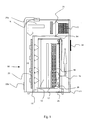
- FIG. 1 shows a side view of a first heating device 10 with a gas circulation device integrated in the housing 11.
- a storage space 12 is formed, the bottom and right side of the housing and the left side of which is bounded by an inner wall 13.
- the storage space 12 adjoins an intermediate ceiling 14 and a blower 15.
- the blower 15 sucks in the air in the storage room 12 and blows it into a gas duct 16 adjoining the ceiling of the housing 11 and designed as a shaft.
- the gas line 16 extends in the horizontal direction.
- the arrows drawn in FIG. 1 illustrate the direction of flow of the air and thus indicate the direction of the circulation circuit of the heating device 10.
- a carousel transport platform 17 Within the storage room 12 and in its bottom area designed as a carousel transport platform 17 is present.
- the circular transport platform 17 is rotatably mounted in its center.
- a cassette 18 is arranged in the storage compartments 19 are sample carrier (not shown here).
- the cassette 18 can be moved by rotation of the transport platform 17 within the storage room 12.
- On the right side of the transport platform 17 adjacent to a known from US 6,129,428 placement device 20 is arranged, through which the cassette 18 is automatically populated.
- a heater 21 is arranged, through the air, after being blown from the fan 15 into the gas line 16 was, is heated.
- the temperature to which the air is heated can be adjusted by regulating the heating power of the heater 21.
- the gas guide 22 is bounded on the left side by the housing 11 and on the right side by the inner wall 13.
- the gas guide 22 extends over the entire length of the storage space 12 and is arranged substantially parallel to the cassettes 18.
- a pollutant and / or germ filter 23 is attached on the inside of the gas guide 22, which is bounded by the inner wall 13, a pollutant and / or germ filter 23 is attached.
- feeds (not shown here) are arranged in the inner wall 13, through which the air flows from the gas guide 22, after flowing through the filter 23 into the storage space 12.
- the air flows into the storage space 12 approximately in the horizontal direction.
- the cassettes 18 can be moved in the direction of the gas guide 22.
- the cassettes 18 When the cassettes 18 are in the vicinity of the gas guide 22, the air flows from the gas guide 22 through the supply (not shown here) through the openings of the storage compartments 19 in the cassette 18 and so can the samples therein (not shown here) heat.
- the cassettes 18 usually have at least one opening and an outlet arranged on the opposite side, so that the air can flow through the cassettes 18 unhindered.
- a gas inlet 24 is further arranged for the supply of fresh air in the recirculation circuit.
- the gas inlet 24 is provided with a pre-filter (not shown here), through which the fresh air is filtered before entering the recirculation cycle.
- a gas outlet 25a is arranged in the ceiling of the housing 11, can be discharged through the air from the circulation circuit. Normally, the outlet 25a is adjusted to discharge approximately the same amount of air introduced through the inlet 24 into the recirculation loop, so that there is an approximately constant pressure within the heater 10.
- the air can also be discharged through the outlet 25b, which is arranged in an outer wall of the housing 11 in the lower region of the gas guide 22.
- the bottom of the storage space 12 is bounded by a switch box 26 in which electrical components (not shown here) are arranged for controlling and regulating the heating device 10.
- Fig. 2 shows the embodiment of Fig. 1 in cross section. It can be seen that the transport platform 17 has holders 27 which are designed to engage in the cassettes 18. Two Cassettes 18 are arranged opposite one another on the transport platform 17 and each engage in a holder 27. The middle region of the lower side wall of the housing 11 is formed as a door 28. The door 28 can be swung open and thus grants access to the storage room 12.
- FIG. 3 shows a second embodiment of a heating device 10 in a side view.
- cassettes 18 are arranged with storage compartments 19.
- storage compartments 19 are samples in microtiter plates (not shown here).
- the right side of the housing 11 has an opening which can be closed by the gas circulation device 29 placed on the housing 11.
- blowers 15 and integrated heating and filtering devices 30 are arranged inside the gas circulation device 29 blowers 15 and integrated heating and filtering devices 30 are arranged.
- the gas circulation device 29 is mounted by hinges 31 on the housing 11 and pivotally mounted.
- the gas circulation device 29 is arranged so that it covers the opening of the housing 11 in the closed state.
- a sealing layer 32 is additionally arranged between the gas circulation 29 and the housing 11.
- an automatic loading device 33 is further attached, through which the cassettes 18 can be automatically equipped with sample carriers. Furthermore, it can be seen that the recirculated air from the gas circulation device 29 flows approximately horizontally into the storage space 12 and also flows through the storage compartments 19 of the cassettes 18 in the horizontal direction.
- Fig. 4 shows the embodiment of Fig. 3 in cross section. It can be seen that inside the gas circulation device 29 there is a region separated by inner walls 34, in which the fans 15 and the integrated heating / filtering devices 30 are arranged. This separated by the inner walls 34 area closes at its sides flush with the storage room 12 from. Inside this area two further intermediate walls 35 are arranged. The inner walls 34 and the intermediate walls 35 are formed continuously from floor to ceiling. The intermediate walls 35 are aligned parallel to the side walls of the housing 11 and begin at the inside end of the housing means 29 and terminate in free space. Thus, the interior of the housing means 29 is divided into three subregions, which, however, all communicate with each other and can exchange air with each other. The arrows indicate the flow direction of the air.
- Air is sucked in by the blowers 15 and then blown out again in the direction of the storage space 12. It first flows through the integrated heating / filtering device 30 and then flows through further feeds (not shown here) in the gasket layer 32 in the storage room 12.
- the two cassettes 18 are each arranged in the vicinity of a feed and are of the air in horizontal Flowed through. The air flows through the cassettes 18, accumulates in the rear region of the storage space 12 and then flows back into the gas recirculation device 29 approximately centrally through a gap between the two cassettes 18.
Landscapes
- Chemical & Material Sciences (AREA)
- Health & Medical Sciences (AREA)
- Life Sciences & Earth Sciences (AREA)
- Engineering & Computer Science (AREA)
- Organic Chemistry (AREA)
- Zoology (AREA)
- Wood Science & Technology (AREA)
- Bioinformatics & Cheminformatics (AREA)
- General Health & Medical Sciences (AREA)
- Biochemistry (AREA)
- Biomedical Technology (AREA)
- Biotechnology (AREA)
- Microbiology (AREA)
- Sustainable Development (AREA)
- Genetics & Genomics (AREA)
- General Engineering & Computer Science (AREA)
- Physics & Mathematics (AREA)
- Analytical Chemistry (AREA)
- Chemical Kinetics & Catalysis (AREA)
- Thermal Sciences (AREA)
- Clinical Laboratory Science (AREA)
- Molecular Biology (AREA)
- Devices For Use In Laboratory Experiments (AREA)
- Sampling And Sample Adjustment (AREA)
Abstract
Description
Die Erfindung betrifft eine Erwärmungsvorrichtung für Proben auf dem Gebiet der Life-Science mit mindestens einer Kassette mit horizontal ausgerichteten Lagerfächern zur Lagerung von Probenträgern, bei welcher Gas zur Erwärmung der Proben auf die Kassette geführt ist sowie ein Verfahren zur Erwärmung solcher Proben. Unter dem Begriff Life-Science versteht man allgemein "die Wissenschaft vom Leben", welche sich mit der Gewinnung und Anwendung von wissenschaftlichen Kenntnissen zum Beispiel auf den Gebieten der Chemie, der Biologie, der Pharmazie, der Biotechnologie, der Physik und der Biochemie beschäftigt. Im Rahmen der wissenschaftlichen Forschung auf diesem Gebiet ist es häufig notwendig, Proben, die üblicherweise in Probenträgern, insbesondere in Mikrotiterplatten, gelagert werden, zu erwärmen. Häufig ist es wünschenswert, die Proben auf eine bestimmte Temperatur zu erwärmen. Ein typisches Anwendungsbeispiel ist das Auftauen von gefrorenen Proben.The invention relates to a heating device for samples in the field of life science with at least one cassette with horizontally oriented storage bins for storage of sample carriers, in which gas for heating the samples is guided on the cassette and a method for heating such samples. The term life science generally refers to "the science of life", which deals with the extraction and application of scientific knowledge, for example in the fields of chemistry, biology, pharmacy, biotechnology, physics and biochemistry. In the context of scientific research in this field, it is often necessary to heat samples which are usually stored in sample carriers, in particular in microtiter plates. Often it is desirable to heat the samples to a certain temperature. A typical application example is the thawing of frozen samples.
Üblicherweise werden die Probenträger in Kassetten gelagert, welche horizontal ausgerichtete Lagerfächer zur Aufnahme der Probenträger aufweisen. Die Lagerfächer sind normalerweise übereinander angeordnet und jedes Fach weist mindestens eine Öffnung zur Einführung der Probenträger auf. Ferner weist jedes Fach mindestens eine weitere Öffnung auf, so dass das die Kassetten umgebene Gas durch die Fächer hindurch strömen kann.Usually, the sample carriers are stored in cassettes, which have horizontally aligned storage compartments for receiving the sample carrier. The storage compartments are usually stacked and each compartment has at least one opening for insertion of the sample carriers. Furthermore, each compartment has at least one further opening, so that the gas surrounding the cassettes can flow through the compartments.
Es ist bekannt, dass Proben zur Auftauung der Umgebungstemperatur ausgesetzt werden oder erwärmte Luft aus der Umgebung auf die mit Proben bestückten Kassetten geleitet wird. Dabei kann allerdings eine für alle Proben gleichmäßiger Temperaturverlauf nicht immer sichergestellt werden.It is known that thawing samples are exposed to ambient temperature or heated ambient air is directed to the sample loaded cassettes. However, a uniform temperature profile for all samples can not always be ensured.
Es ist Aufgabe der vorliegenden Erfindung, eine Erwärmungsvorrichtung sowie ein Verfahren zur Erwärmung von Proben anzugeben, bei der eine kontrollierte und gleichmäßige Erwärmung der Proben erreicht wird.It is an object of the present invention to provide a heating device and a method for heating samples, in which a controlled and uniform heating of the samples is achieved.
Diese Aufgabe wird bei der Erwärmungsvorrichtung der Eingangs beschriebenen Art dadurch gelöst, dass die Erwärmungsvorrichtung ein Gehäuse aufweist, welches einen darin angeordneten Lagerraum, der zur Zu- und Abfuhr von Gas und zur Lagerung der mindestens einen Kassette ausgebildet ist, aufweist. Im Lagerraum ist eine Gasumwälzungseinrichtung zur Umwälzung des Gases vorhanden.This object is achieved in the heating device of the type described input, characterized in that the heating device comprises a housing which has a storage space arranged therein, which is designed for the supply and removal of gas and for storage of the at least one cassette. In the storage room a gas circulation device for circulation of the gas is present.
Durch das Vorhandensein eines Gehäuses, durch den der Lagerraum von der Umwelt abschließbar ist, werden die im Lagerraum gelagerten Proben nicht der Umgebung ausgesetzt und die Gefahr einer Kontamination kann somit reduziert werden. Die Proben können dabei manuell oder durch ein automatisiertes Be- und Entladungssystem in den Lagerraum eingeführt werden. Ein solche automatisierte Be- und Entladungsvorrichtung ist zum Beispiel aus der US 6,129,428 bekannt. Nach Einlagerung der Proben in den Lagerraum wird das Gehäuse verschlossen und der Lagerraum somit gegenüber der Umwelt abgeschottet.The presence of a housing that seals the storage room from the environment prevents the samples stored in the storage room from being exposed to the environment and thus reduces the risk of contamination. The samples can be introduced manually or through an automated loading and unloading system in the storage room. Such an automated loading and unloading device is known for example from US 6,129,428. After storage of the samples in the storage room, the housing is closed and thus the storage room is sealed off from the environment.
Ein weiterer Vorteil der Erfindung liegt darin, dass es durch die Ausbildung des Lagerraums zur Zu- und Abfuhr von Gas möglich ist, Gas zur Erwärmung der Proben auf die Kassetten zu führen. Durch die geschlossenen Anordnung des Lagerraumes, ist es möglich, die Gasströmung zu steuern und somit eine gleichmäßigere Erwärmung der Proben zu erreichen. Durch die Gasumwälzeinrichtung ist es weiterhin möglich, nur das bereits im Lagerraum vorhandene Gas zur Erwärmung der Proben zu benutzen, ohne somit eine Kontamination aus der Umgebungsluft zu riskieren. Mit der Erfindung ist es möglich, das Erwärmen , insbesondere Auftauen, der Proben mit kontrollierter Geschwindigkeit, gleichmäßig und schonend durchzuführen, so dass eine optimale Weiterverarbeitung der Proben möglich ist, ohne dass die Proben durch den Erwärmungsvorgang kontaminiert oder beschädigt werden.Another advantage of the invention is that it is possible by the formation of the storage space for the supply and removal of gas to lead gas for heating the samples on the cassettes. Due to the closed arrangement of the storage space, it is possible to control the gas flow and thus to achieve a more uniform heating of the samples. Due to the gas circulation device, it is furthermore possible to use only the gas already present in the storage space for heating the samples, without risking contamination from the ambient air. With the invention it is possible to carry out the heating, in particular thawing, of the samples at controlled speed, uniformly and gently, so that an optimal further processing of the samples is possible without the samples being contaminated or damaged by the heating process.
Die Öffnung des Gehäuses ist so anzuordnen, dass sie einen ausreichenden Zugriff auf den Lagerraum gewährt und somit das einfache Ein- und Ausladen von Kassetten in den Lagerraum ermöglicht. Der Lagerraum kann so ausgebildet sein, dass er entweder den gesamten Bereich, der vom Gehäuse umschlossen ist, ausfüllt oder nur einen Teil dieses Bereichs.The opening of the enclosure should be arranged so as to provide sufficient access to the storage room, thus allowing easy loading and unloading of cassettes into the storage room. The storage space may be configured to either fill the entire area enclosed by the housing or only a portion of that area.
In einer bevorzugten Ausführungsform weist die Gasumwälzungseinrichtung eine Zuführung auf, durch die externes Gas zum Umwälzkreislauf zugeführt werden kann. Zusätzlich weist die Gasumwälzungseinrichtung auch eine Abführung auf, durch die Gas aus dem Umwälzkreislauf abgeführt und in die Umgebungsluft außerhalb des Gehäuses der Erwärmungsvorrichtung abgegeben werden kann. Dies hat den Vorteil, dass das Gas innerhalb des Umwälzkreislaufes durch externes Gas ersetzt und somit erneuert werden kann. Hierbei ist es möglich, das Gas im Umwälzkreislauf komplett auszutauschen oder schrittweise externes Gas zuzuführen und fortlaufend einen Teil des Gasgemisches, bestehend aus dem ursprünglichen Gas und dem neu zugeführten externen Gas, aus dem Umwälzkreislauf abzulassen. Durch Einstellung der Zu- und Abführmengen von Gas aus dem Umwälzkreislauf ist es weiterhin möglich, den Gasdruck innerhalb des Umwälzkreislaufes zu variieren und somit an die jeweiligen Proben angepasste Umweltbedingungen zu erzeugen.In a preferred embodiment, the gas circulation device has a feed through which external gas can be supplied to the circulation circuit. In addition, the gas circulation device also has a discharge, through which gas can be removed from the circulation circuit and discharged into the ambient air outside the housing of the heating device. This has the advantage that the gas can be replaced within the recirculation by external gas and thus renewed. In this case, it is possible to exchange the gas completely in the recirculation circuit or to gradually supply external gas and continuously to part of the gas mixture consisting of the original gas and the newly supplied external gas to drain from the recirculation cycle. By adjusting the supply and Abführmengen of gas from the recirculation cycle, it is also possible to vary the gas pressure within the recirculation loop and thus to produce adapted to the respective samples environmental conditions.
In einer weiteren bevorzugten Ausführungsform weist die Gasumwälzungseinrichtung Mittel zur Aufbereitung des umzuwälzenden Gases auf. Unter umzuwälzendem Gas wird das gesamte Gas im Umwälzkreislauf, das heißt sowohl das im Lagerraum als auch das in der Gasumwälzeinrichtung befindliche Gas, verstanden. Durch die Mittel zur Aufbereitung ist es möglich, physikalische oder chemische Eigenschaften des umzuwälzenden Gases zu verändern und somit optimale Bedingungen für den Erwärmungsprozess der jeweiligen Proben zu schaffen.In a further preferred embodiment, the gas circulation device has means for processing the gas to be circulated. Under gas to be circulated, the entire gas in the circulation, that is both the gas in the storage room as well as in the gas circulation means understood. By means of the treatment, it is possible to change physical or chemical properties of the gas to be circulated and thus to create optimal conditions for the heating process of the respective samples.
Zeckmäßigerweise weist die Gasumwälzungseinrichtung eine Gasführung auf. Unter Gasführung kann dabei grundsätzlich jedes Medium verstanden werden, das zur Führung von Gas geeignet ist, beispielsweise Leitungen, Rohre, Wände, etc. Die Gasführung ist dabei so ausgebildet, dass sie das Gas entlang der gesamten Länge der mindestens einen Kassette führt und in im Wesentlichen horizontaler Ausrichtung in die Kassette zur Durchströmung einleitet. Die Führung des Gases entlang der gesamten Länge der Kassette stellt sicher, dass das Gas in allen Bereichen der Kassette weitestgehend gleichmäßig verteilt ist und so eine gleichförmige Durchströmung und daraus resultierend auch eine gleichmäßige Erwärmung der Proben in der Kassette sichergestellt wird. Die Gasführung wird zweckmäßigerweise so angeordnet, dass das Gas zumindest entlang einer Seite der Kassette geführt wird, welche Öffnungen aufweist und so eine Durchströmung der Kassette mit Gas erlaubt. Die horizontale Ausrichtung der Strömung des eingeleiteten Gases in die Kassette stellt weiterhin sicher, dass sämtliche Lagerfächer durchströmt werden, da diese ebenfalls horizontal ausgerichtet sind. Die Gasführung kann sowohl innerhalb als auch außerhalb des Lagerraums angeordnet sein. Falls sie außerhalb des Lagerraums angeordnet ist, ist die Zuführung des Gases von der Gasführung in den Lagerraum so anzuordnen und auszubilden, dass eine ausreichende Durchströmung der mindestens einen Kassette gewährleistet ist.Zeckmäßigerweise, the gas circulation device on a gas guide. Under gas guidance can be understood in principle any medium that is suitable for guiding gas, such as pipes, pipes, walls, etc. The gas guide is designed so that it leads the gas along the entire length of the at least one cassette and in the Essentially horizontal orientation in the cartridge to the flow initiates. The guidance of the gas along the entire length of the cassette ensures that the gas is distributed as uniformly as possible in all areas of the cassette, thus ensuring a uniform flow and, as a result, even heating of the samples in the cassette. The gas guide is expediently arranged so that the gas is guided at least along one side of the cassette, which has openings and thus allows gas to flow through the cassette. The horizontal orientation of the flow of the introduced gas into the cassette further ensures that all storage compartments are flowed through, since these are also aligned horizontally. The gas guide can be arranged both inside and outside the storage room. If it is arranged outside the storage space, the supply of the gas from the gas guide into the storage space is to be arranged and designed such that a sufficient flow through the at least one cassette is ensured.
In einer weiteren bevorzugten Ausführungsform wird die Gasführung als Schacht, insbesondere als rechteckiger Schacht ausgebildet, wobei der Schacht an den Lagerraum angrenzt und sich über die Länge des Lagerraumes erstreckt. Da schrankartige Gehäuse, wie sie auch für die erfindungsgemäße Erwärmungsvorrichtung verwendet werden können, häufig quaderförmig ausgebildet sind, bietet es sich an, den Gasführungsschacht mit rechteckigem Querschnitt auszubilden. Bevorzugt grenzt der Schacht in der Nähe der mindestens einen Kassette an den Lagerraum an, so dass das Gas nach Einführung in den Lagerraum von der Gasführung aus, direkt auf die mindestens eine Kassette geleitet werden kann. Zweckmäßigerweise wird die Kassette hierbei mit ihren Öffnungen zur Zuführung in den Lagerraum ausgerichtet. Vorteilhaft ist, dass ein Schacht vergleichsweise einfach ausgebildet werden kann, beispielsweise kann er aus den Wänden des Gehäuses und/oder des Lagerraumes gebildet werden. Das sich der Gasführungsschacht über die gesamte Länge des Lagerraums erstreckt, gewährleistet, dass eine gleichmäßige Durchströmung des Lagerraums und somit auch der mindestens einen Kassette mit Gas erreicht wird.In a further preferred embodiment, the gas guide is formed as a shaft, in particular as a rectangular shaft, wherein the shaft adjacent to the storage space and extending over the length of the storage space. Since cabinet-like housing, as can also be used for the heating device according to the invention, are often formed cuboid, it makes sense to form the gas guide shaft with a rectangular cross-section. The shaft preferably adjoins the storage space in the vicinity of the at least one cassette, so that the gas, after introduction into the storage space, can be directed from the gas guide directly to the at least one cassette. Conveniently, the cassette is hereby aligned with their openings for feeding into the storage room. It is advantageous that a shaft can be formed comparatively simple, for example, it can be formed from the walls of the housing and / or the storage room. The fact that the gas guide shaft extends over the entire length of the storage space, ensures that a uniform flow through the storage space and thus also the at least one cassette is achieved with gas.
Bevorzugterweise ist die Gasumwälzungseinrichtung in das Gehäuse integriert ausgebildet. Dabei kann die Gasumwälzungseinrichtung sowohl innerhalb als auch außerhalb des Lagerraums angeordnet sein. Es ist auch möglich, nur einen Teil der Gasumwälzungseinrichtung innerhalb des Lagerraums und einen anderen Teil außerhalb, also zwischen Lagerraum und Gehäuse, anzuordnen. Vorteilhaft ist hierbei, dass durch die Integrierung der Gasumwälzungseinrichtung in das Gehäuse eine kompakte Bauweise der Erwärmungsvorrichtung verwirklicht werden kann. Alternativ ist die Gasumwälzungseinrichtung separat und auf das Gehäuse aufsetzbar ausgebildet, wobei es in dieser Ausführungsform mit Befestigungsmitteln, bevorzugterweise mit Scharnieren, Schrauben, Bolzen oder durch Verschweißen, am Gehäuse angebracht wird. Dies hat den Vorteil, dass die Gasumwälzungseinrichtung separat vom Rest der Erwärmungsvorrichtung gefertigt werden kann und die Endmontage erst unmittelbar vor Inbetriebnahme unternommen werden muss. Weiterhin ist es hierdurch relativ leicht möglich, andere in Laboren weit verbreitete Vorrichtungen, wie zum Beispiel Klimaschränke, Kühlschränke, Lagerungsvorrichtungen, Lagerschränke für Proben, etc., umzurüsten und zu erfindungsgemäßen Erwärmungsvorrichtungen auszubilden.Preferably, the gas circulation device is formed integrated into the housing. In this case, the gas circulation device can be arranged both inside and outside of the storage room. It is also possible to arrange only a part of the gas circulation device within the storage space and another part outside, ie between storage space and housing. It is advantageous here that a compact design of the heating device can be realized by integrating the gas circulation device in the housing. Alternatively, the Gasumwälzungseinrichtung is formed separately and placed on the housing, wherein it is attached in this embodiment with fastening means, preferably with hinges, screws, bolts or by welding, on the housing. This has the advantage that the gas circulation device can be manufactured separately from the rest of the heating device and the final assembly must be undertaken only immediately before commissioning. Furthermore, this makes it relatively easy to retrofit other widely used in laboratories devices such as air conditioning cabinets, refrigerators, storage devices, storage cabinets for samples, etc., and form heating devices according to the invention.
Bei einer auf das Gehäuse aufsetzbar ausgebildeten Gasumwälzungseinrichtung, wird diese bevorzugterweise im Bereich der Öffnung des Gehäuses angeordnet und mittels Scharnieren am Gehäuse zur schwenkbaren Verschließung der Öffnung befestigt. Durch die Befestigung mittels Scharnieren kann die Gasumwälzungseinrichtung, ähnlich einer Tür, seitlich auf- bzw. zugeschwenkt werden und ermöglicht so den Zugang zum Lagerraum zur Be- bzw. Entladung von Kassetten. Zweckmäßigerweise schließt die Gasumwälzungseinrichtung die Öffnung des Gehäuses dichtend ab, so dass ein Austritt von Gas aus dem Inneren des Gehäuses vermieden wird.In the case of a gas circulation device which can be placed on the housing, this is preferably arranged in the region of the opening of the housing and fastened by means of hinges to the housing for the pivotable closure of the opening. By fastening by means of hinges, the gas circulation device, similar to a door, laterally open or be pivoted and thus allows access to the storage room for loading and unloading of cassettes. Expediently, the gas recirculation device seals the opening of the housing so that escape of gas from the interior of the housing is avoided.
Bevorzugterweise wird die Gasführung versetzt von der Öffnung des Gehäuses angeordnet. Dies ist allerdings nur bevorzugt, solange die Gasumwälzungseinrichtung nicht als Tür zur Verschließung der Öffnung des Gehäuses ausgebildet ist. Vorteilhaft ist diese Anordnung der Gasführung deshalb, da dadurch die Be- und Entladung des Lagerraums nicht beeinträchtigt wird. Zweckmäßigerweise weist die Gasumwälzungseinrichtung einen Antrieb zur Umwälzung des Gases auf. Besonders bevorzugt ist der Antrieb als Gebläse ausgebildet. Das Gebläse wird dabei typischerweise so angeordnet, dass es das Gas innerhalb des Umwälzkreislaufes auf einer Seite ansaugt und auf der anderen ausbläst und so für eine kontinuierliche Strömung sorgt.Preferably, the gas guide is arranged offset from the opening of the housing. However, this is only preferred as long as the gas circulation device is not designed as a door for closing the opening of the housing. This arrangement of the gas guide is advantageous because it does not affect the loading and unloading of the storage space. Expediently, the gas circulation device has a drive for circulating the gas. Particularly preferred is the Drive designed as a fan. The fan is typically arranged so that it draws in the gas within the circulation on one side and blows out on the other, thus providing a continuous flow.
In einer weiteren Ausführungsform werden mehrere Kassetten innerhalb des Lagerraums gelagert. Weiterhin sind die Kassetten mittels Bewegungsmitteln ortsverschiebbar ausgebildet und mittels einer Steuereinrichtung in Richtung der Gasführung bewegbar. Durch die Bewegung der Kassetten in Richtung der Gasführung ist es möglich, die Kassetten abwechselnd so anzuordnen, dass eine Durchströmung der Kassetten erreicht wird. Durch die Steuereinrichtung sind die Bewegungen der Kassetten so einstellbar, dass eine in etwa gleichmäßige Durchströmung aller Kassetten gewährleistet ist. Sind in allen Kassetten gleiche Proben vorhanden, ist es zweckmäßig die Kassetten kontinuierlich in Richtung der Gasführung zu bewegen, so dass sich für jede Kassette eine etwa gleiche Durchströmdauer einstellt. Bei unterschiedlichen Proben (zum Beispiel unterschiedliche Inhalte, unterschiedliche Temperaturen, unterschiedliche Menge, etc.) ist möglich, die Steuereinrichtung so einzustellen, dass die jeweiligen Kassetten unterschiedlich lange in der Nähe der Gasführung verweilen, abhängig davon, welche Proben wieviel Zeit zur Erwärmung benötigen. Hierdurch kann die Gleichmäßigkeit der Erwärmung der Proben weiter verbessert werden. Es ist weiterhin zweckmäßig, dass die Steuereinrichtung die Verweilzeit der Kassetten in der Nähe der Gasführung in Abhängigkeit der Strömungsgeschwindigkeit des auf die Kassetten geführten Gases steuert. Die Abhängigkeit der Verweildauer der Kassetten von der Strömungsgeschwindigkeit des auf die Kassetten geführten Gases stellt sicher, dass bei jeder Strömungsgeschwindigkeit eine ausreichende Durchströmung der Kassetten erreicht wird.In another embodiment, multiple cassettes are stored within the storage room. Furthermore, the cassettes are formed displaceable by means of movement means and movable by means of a control device in the direction of the gas guide. By the movement of the cassettes in the direction of the gas guide, it is possible to arrange the cassettes alternately so that a flow through the cassettes is achieved. By the control device, the movements of the cassettes are adjustable so that an approximately uniform flow of all cassettes is ensured. If the same samples are present in all cassettes, it is expedient to move the cassettes continuously in the direction of the gas guide, so that an approximately equal flow duration is established for each cassette. With different samples (for example, different contents, different temperatures, different amount, etc.) it is possible to set the control device so that the respective cassettes stay for different lengths in the vicinity of the gas guide, depending on which samples take how much time to heat. As a result, the uniformity of the heating of the samples can be further improved. It is also expedient for the control device to control the residence time of the cassettes in the vicinity of the gas guide as a function of the flow velocity of the gas guided onto the cassettes. The dependence of the residence time of the cassettes on the flow rate of the gas fed to the cassettes ensures that sufficient flow through the cassettes is achieved at each flow rate.
In einer bevorzugten Ausführungsform umfassen die Bewegungsmittel eine horizontal verschwenkbare oder rotierbare Kassettenlagerplattform. Vorteilhafterweise ist die Kassettenlagerplattform als Drehscheibe, die um ihren Mittelpunkt rotierbar ist, ausgebildet. Diese Ausbildungsform wird im Allgemeinen auch als "Karussell" bezeichnet. Weiterhin ist es bevorzugt, dass die Bewegungsmittel eine Transporteinrichtung umfassen, die zum Transport von einzelnen Probenträgern senkrecht und parallel zur Rotationsachse der Drehscheibe ausgebildet ist. Durch Öffnen der Gehäuseöffnung wird der Zugriff auf den Lagerraum gewährt und die Kassetten können manuell in den Lagerraum eingebracht werden. Die Kassetten werden auf der Drehscheibe angeordnet und können somit durch Drehung in Richtung der Gasführung bewegt werden. Die Transporteinrichtung, welche bereits aus der US 6,129,428 bekannt ist, weist ein schwenkbar und horizontal verschiebbar ausgebildetes Transportelement auf, durch welches ein Probenträger zur Zeit transportierbar ist. Das Transportelement ist in einen Lift integriert, durch welchen die ein- und auszulagernden Probenträger auch vertikal bewegbar sind. Durch eine zusätzliche, verschließbare Be- und Entladungsöffnung im Gehäuse, dessen Größe an die Größe der Probenträger angepasst ist, kann ein Probenträger zur Zeit von der Transporteinrichtung aufgenommen werden und in ein Lagerfach einer Kassette, welche auf der Drehscheibe angeordnet ist, eingebracht werden. Durch eine Schleusenvorrichtung in der Be- und Entladungsöffnung kann eine Kontamination des Innenraums des Gehäuses beim Be- und Entladen vermieden werden.In a preferred embodiment, the moving means comprise a horizontally pivotable or rotatable cassette storage platform. Advantageously, the cassette storage platform is designed as a hub which is rotatable about its center. This form of training is also commonly referred to as a "carousel". Furthermore, it is preferred that the movement means comprise a transport device, which is designed for the transport of individual sample carriers perpendicular and parallel to the axis of rotation of the turntable. By opening the housing opening access to the storage room is granted and the cassettes can be manually inserted into the storage room. The cassettes are arranged on the turntable and can thus be moved by rotation in the direction of the gas guide. The transport device, which is already known from US 6,129,428, has a pivotable and horizontally displaceable trained transport element, through which a sample carrier is currently transportable. The transport element is integrated into a lift, by means of which the sample carriers to be loaded and unloaded are also vertically movable. By an additional, lockable loading and unloading opening in the housing, the size of the Adjusted size of the sample carrier, a sample carrier can currently be picked up by the transport device and in a storage compartment of a cassette, which is arranged on the turntable, are introduced. By a lock device in the loading and unloading a contamination of the interior of the housing during loading and unloading can be avoided.
Vorteilhafterweise sind die Kassetten auf der Transportplattform im Wesentlichen gleichmäßig verteilt. Dadurch wird die Gleichmäßigkeit der Erwärmung der Proben weiter verbessert.Advantageously, the cassettes are distributed substantially uniformly on the transport platform. This further improves the uniformity of the heating of the samples.
Bevorzugterweise wird das externe Gas dem Umwälzkreislauf unter einem bestimmten Mischungsverhältnis beigemischt. Hierdurch kann eine konstante und kontinuierliche Beimischung von externem Gas zum Umwälzkreislauf erreicht werden und die Gasmischung so auf die jeweiligen Erfordernisse der Proben eingestellt werden.Preferably, the external gas is added to the circulation circuit under a certain mixing ratio. As a result, a constant and continuous admixture of external gas can be achieved for Umwälzkreislauf and the gas mixture can be adjusted to the particular requirements of the samples.
In einer weiteren bevorzugten Ausführungsform weist die Zuführung des externen Gases ein Schadstoff- und/oder Keimfilter zur Filterung des externen Gases auf. Durch die Filterung des externen Gases wird sichergestellt, dass durch die Zuführung von fremden Gas in den Umwälzkreislauf keine Schadstoffe und Keime in den Lagerraum gelangen und eine Kontamination der Proben somit vermieden wird.In a further preferred embodiment, the supply of the external gas to a pollutant and / or germ filter for filtering the external gas. The filtering of the external gas ensures that no pollutants and germs enter the storage room due to the supply of foreign gas into the recirculation circuit, thus avoiding contamination of the samples.
In einer weiteren Ausführungsform weisen die Mittel zur Aufbereitung des umzuwälzenden Gases mindestens einen Schadstoff- und/oder Keimfilter auf, durch welchen das Gas während der Umwälzung strömt. Vorteilhaft ist hierbei, dass das Risiko einer Kontaminierung der Proben weiter verringert wird. Bevorzugt wird der mindestens eine Filter entlang der Gasführung angeordnet. Weiterhin ist es bevorzugt, den Filter von der Öffnung des Gehäuses aus zugänglich anzuordnen. Hierdurch wird die Wartung und der Austausch der Filter erleichtert und somit ganz allgemein die Handhabung der Erwärmungsvorrichtung verbessert.In a further embodiment, the means for processing the gas to be circulated at least one pollutant and / or germ filter, through which the gas flows during the circulation. The advantage here is that the risk of contamination of the samples is further reduced. Preferably, the at least one filter is arranged along the gas guide. Furthermore, it is preferable to arrange the filter accessible from the opening of the housing. As a result, the maintenance and replacement of the filter is facilitated and thus generally improves the handling of the heating device.
In einer weiteren Ausführungsform weist der mindestens eine Filter verschiedene Dicken und/oder verschiedene Dichtigkeiten auf. Diese Eigenschaften haben Auswirkung auf die Geschwindigkeit, mit der das Gas den Filter durchströmt und bei entsprechender Anordnung der unterschiedlichen Filterstärken können somit unterschiedliche Strömungsgeschwindigkeiten des Gases ausgeglichen werden und die Gleichmäßigkeit des Gasstroms weiter verbessert werden.In a further embodiment, the at least one filter has different thicknesses and / or different tightnesses. These properties have an effect on the speed with which the gas flows through the filter and with appropriate arrangement of the different filter strengths, thus different flow velocities of the gas can be compensated and the uniformity of the gas flow can be further improved.
In einer weiteren bevorzugten Ausführungsform weisen die Mittel zur Aufbereitung des umzuwälzenden Gases weiterhin eine Heizvorrichtung zur Erwärmung des Gases auf. Hierdurch ist es möglich, das umzuwälzende Gas auf eine bestimmte Temperatur zu erwärmen. Somit kann eine optimale Erwärmungstemperatur für die jeweiligen Proben erreicht werden. Bevorzugt wird die Heizvorrichtung entlang der Gasführung angeordnet. Hierbei kann die Heizvorrichtung beispielsweise als Heizschlange ausgebildet sein, an der das Gas innerhalb der Gasführung vorbeiströmt und dadurch erwärmt wird.In a further preferred embodiment, the means for processing the gas to be circulated further comprise a heating device for heating the gas. This makes it possible to heat the gas to be circulated to a certain temperature. Thus, an optimum heating temperature for the respective samples can be achieved. The heating device is preferred arranged along the gas guide. Here, the heater may be formed, for example, as a heating coil, where the gas flows past within the gas guide and is heated thereby.
Zweckmäßigerweise weist die Erwärmungsvorrichtung weiterhin eine Kontrolleinrichtung auf, durch die die Temperatur im Lagerraum innerhalb einer bestimmten Temperaturspanne gehalten werden kann. Hierdurch wird sichergestellt, dass die Proben keinen zu hohen bzw. zu niedrigen Temperaturen ausgesetzt sind und die Probenqualität somit nicht beeinträchtigt wird.Conveniently, the heating device further comprises a control device, by means of which the temperature in the storage room can be kept within a certain temperature range. This ensures that the samples are not exposed to too high or too low temperatures and thus the sample quality is not impaired.
Bevorzugterweise besteht das umzuwälzende Gas aus Luft. Dadurch wird der Aufbau und die Handhabung der Erwärmungsvorrichtung weiter vereinfacht. Zweckmäßigerweise wird bei dieser Ausführungsform als externes Gas Frischluft dem Umwälzkreislauf zugeführt. Hierbei ist es weiterhin besonders bevorzugt, dass der Anteil an Frischluft im Umwälzkreislauf ungefähr zehn Prozent entspricht.Preferably, the gas to be circulated consists of air. This further simplifies the construction and handling of the heating device. Appropriately, in this embodiment, fresh air is supplied to the recirculation circuit as an external gas. In this case, it is further particularly preferred that the proportion of fresh air in the circulation corresponds to approximately ten percent.
In einer weiteren bevorzugten Ausführungsform ist die Erwärmungsvorrichtung integriert in einen Inkubator oder einen Klimaschrank ausgebildet. Hierdurch wird der Erwärmungsprozess der Proben weiter vereinfacht, da die Umlagerung der Proben in eine separate Erwärmungsvorrichtung nicht mehr durchgeführt werden muss ist. Zusätzlich wird der Platzbedarf innerhalb des Labors reduziert.In a further preferred embodiment, the heating device is integrated in an incubator or a climate chamber. As a result, the heating process of the samples is further simplified because the rearrangement of the samples in a separate heating device is no longer required to be performed. In addition, the space required within the laboratory is reduced.
Weiterhin wird die der Erfindung zugrunde liegende Aufgabe durch ein Verfahren zur Erwärmung von Proben auf dem Gebiet der Life-Science, welche innerhalb eines Lagerraums angeordnet sind und bei welchen Gas zur Erwärmung der Proben auf diese geführt wird, dadurch gelöst, dass das Gas im Lagerraum umgewälzt wird, externes Gas zum Umwälzkreislauf zugeführt wird, das umzuwälzende Gas erwärmt wird, eine Filterung des umzuwälzenden Gases durch Keim- und Schadstofffilter durchgeführt wird und ein Teil des umzuwälzenden Gases aus dem Umwälzkreislauf wieder ausgeführt wird. Zur Erreichung einer kontinuierlichen Erwärmung werden diese Schritte wiederholt.Furthermore, the object underlying the invention is achieved by a method for heating samples in the field of life science, which are arranged within a storage space and in which gas for heating the samples is guided on this, achieved by the gas in the storage room is recirculated, external gas is supplied to Umwälzkreislauf, the gas to be circulated is heated, a filtering of the gas to be circulated through germ and pollutant filter is performed and a part of the gas to be circulated from the circulation circuit is carried out again. To achieve continuous heating, these steps are repeated.
In einer bevorzugten Verfahrensvariante wird das externe Gas vor dem Zuführen zum Umwälzkreislauf mittels Keim- und Schadstofffiltern gefiltert. Hierdurch wird das Risiko einer Kontamination der Proben weiter verringert..In a preferred variant of the method, the external gas is filtered by means of germ and pollutant filters before it is fed to the recirculation cycle. This further reduces the risk of contamination of the samples.
Weiterhin ist es bevorzugt, die Zuführung von externem Gas unter vorherbestimmten Mischverhältnissen durchzuführen. Somit kann ein optimales Gasgemisch zur Erwärmung der Proben erreicht werden.Furthermore, it is preferable to carry out the supply of external gas under predetermined mixing ratios. Thus, an optimal gas mixture for heating the samples can be achieved.
In einer weiteren bevorzugten Verfahrensvariante besteht das Gas im Umwälzkreislauf aus Luft. Entsprechend ist es weiterhin bevorzugt, dass das externe Gas aus Frischluft besteht. Bei dieser Verfahrensvariante ist es weiterhin besonders bevorzugt, dass der Anteil an Frischluft im Umwälzkreislauf im Wesentlichen zehn Prozent beträgt.In a further preferred variant of the method, the gas in the circulation loop consists of air. Accordingly, it is further preferred that the external gas consists of fresh air. In this process variant Furthermore, it is particularly preferred that the proportion of fresh air in the circulation is substantially ten percent.
Nachfolgend wird die Erfindung anhand in den Zeichnungen dargestellter Ausführungsbeispiele weiter beschrieben. Es zeigen schematisch:
- Fig. 1
- eine Seitenansicht einer ersten Erwärmungsvorrichtung mit im Gehäuse integrierter Gasumwälzungseinrichtung;
- Fig. 2
- die Ausführungsform aus Fig. 1 im Querschnitt;
- Fig. 3
- eine Seitenansicht einer zweiten Erwärmungsvorrichtung mit auf das Gehäuse aufgesetzter Gasumwälzungseinrichtung; und
- Fig. 4
- die Ausführungsform aus Fig. 3 im Querschnitt. ,
- Fig. 1
- a side view of a first heating device with integrated in the housing gas circulation device;
- Fig. 2
- the embodiment of Figure 1 in cross section.
- Fig. 3
- a side view of a second heating device mounted on the housing gas circulation device; and
- Fig. 4
- the embodiment of Fig. 3 in cross section. .
Bei den in den Figuren dargestellten, verschiedenen Ausführungsformen der Erfindung sind gleiche Teile mit gleichen Bezugszeichen versehen.In the illustrated in the figures, various embodiments of the invention, like parts are given the same reference numerals.
Fig. 1 zeigt eine Seitenansicht einer ersten Erwärmungsvorrichtung 10 mit einer im Gehäuse 11 integrierten Gasumwälzungsvorrichtung. Im Inneren des Gehäuses 11 ist ein Lagerraum 12 ausgebildet, dessen Boden und rechte Seite vom Gehäuse und dessen linke Seite von einer Innenwand 13 begrenzt wird. An seinem oberen Ende grenzt der Lagerraum 12 an eine Zwischendecke 14 und an ein Gebläse 15. Das Gebläse 15 saugt die im Lagerraum 12 befindliche Luft an und bläst sie in eine an die Decke des Gehäuses 11 angrenzende und als Schacht ausgebildete Gasleitung 16 ein. Die Gasleitung 16 verläuft in horizontaler Richtung. Die in Fig. 1 eingezeichneten Pfeile verdeutlichen die Strömungsrichtung der Luft und zeigen somit die Richtung des Umwälzkreislaufes der Erwärmungsvorrichtung 10 an.1 shows a side view of a
Innerhalb des Lagerraums 12 und in dessen Bodenbereich ist eine als Karussell ausgebildete Transportplattform 17 vorhanden. Die kreisförmige Transportplattform 17 ist in ihrem Mittelpunkt drehbar gelagert. Auf der Transportplattform 17 ist eine Kassette 18 angeordnet, in deren Lagerfächern 19 sich Probenträger (hier nicht dargestellt) befinden. Die Kassette 18 kann durch Rotation der Transportplattform 17 innerhalb des Lagerraums 12 bewegt werden. Auf der rechten Seite an die Transportplattform 17 angrenzend ist eine aus der US 6,129,428 bekannte Bestückungsvorrichtung 20 angeordnet, durch die die Kassette 18 automatisch bestückbar ist.Within the
Innerhalb der Gasleitung 16, direkt hinter dem Gebläse 15 in Strömungsrichtung ist eine Heizvorrichtung 21 angeordnet, durch die Luft, nachdem sie aus dem Gebläse 15 in die Gasleitung 16 eingeblasen wurde, erwärmt wird. Die Temperatur, auf die die Luft erwärmt wird, kann dabei durch Regulierung der Heizleistung der Heizvorrichtung 21 eingestellt werden. Nachdem die Luft die Heizvorrichtung 21 passiert, strömt sie weiter die Gasleitung 16 in horizontaler Richtung entlang, bis sie in eine vertikal ausgerichtete und als rechteckiger Schacht ausgebildete Gasführung 22 einströmt. Die Gasführung 22 wird auf der linken Seite von dem Gehäuse 11 und auf ihrer rechten Seite von der Innenwand 13 begrenzt. Die Gasführung 22 erstreckt sich über die gesamte Länge des Lagerraumes 12 und ist im Wesentlichen parallel zu den Kassetten 18 angeordnet. Durch dieses Anordnung wird sichergestellt, dass sich die in die Gasführung 22 einströmende Luft über die gesamte Länge der Kassetten 18 gleichmäßig verteilt. An der Innseite der Gasführung 22, die durch die Innenwand 13 begrenzt wird, ist ein Schadstoff- und/oder Keimfilter 23 angebracht. Zusätzlich sind in der Innenwand 13 Zuführungen (hier nicht dargestellt) angeordnet, durch die die Luft aus der Gasführung 22, nach Durchströmen des Filters 23 in den Lagerraum 12 einströmt. Wie in der Fig. 1 zu erkennen ist, strömt die Luft ungefähr in horizontaler Richtung in den Lagerraum 12 ein. Durch Drehen der Transportplattform 17 können die Kassetten 18 in Richtung der Gasführung 22 bewegt werden. Wenn die Kassetten 18 in der Nähe der Gasführung 22 sind, strömt die Luft aus der Gasführung 22 durch die Zuführung (hier nicht dargestellt) durch die Öffnungen der Lagerfächer 19 in die Kassette 18 ein und kann so die darin befindlichen Proben (hier nicht dargestellt) erwärmen. Die Kassetten 18 weisen üblicherweise mindestens eine Öffnung und einen an der gegenüberliegenden Seite angeordneten Ausgang auf, so dass die Luft die Kassetten 18 ungehindert durchströmen kann.Within the
An der rechten Seitenwand des Gehäuses 11 ist weiterhin eine Gaseinlass 24 für die Zuführung von Frischluft in den Umwälzkreislauf angeordnet. Die Gaseinlass 24 ist mit einem Vorfilter (hier nicht dargestellt) versehen, durch den die Frischluft vor Eintritt in den Umwälzkreislauf gefiltert wird. Abgehend von der Gasleitung 16 ist in der Decke des Gehäuses 11 ein Gasauslass 25a angeordnet, durch den Luft aus dem Umwälzkreislauf abgelassen werden kann. Normalerweise wird der Auslass 25a so eingestellt, dass durch ihn in etwa die gleiche Menge Luft abgelassen wird, die durch den Einlass 24 in den Umwälzkreislauf eingelassen wird, so dass innerhalb der Erwärmungsvorrichtung 10 ein etwa konstanter Druck herrscht. Alternativ oder zusätzlich kann die Luft auch durch den Auslass 25b abgelassen werden, der in einer Außenwand des Gehäuses 11 im unteren Bereich der Gasführung 22 angeordnet ist. Der Boden des Lagerraumes 12 wird durch einen Schaltkasten 26 begrenzt, in dem elektrische Bauteile (hier nicht dargestellt) zur Steuerung und Regelung der Erwärmungsvorrichtung 10 angeordnet sind.On the right side wall of the
Fig. 2 zeigt die Ausführungsform aus Fig. 1 im Querschnitt. Es ist zu erkennen, dass die Transportplattform 17 Halterungen 27 aufweist, die zum Eingriff in die Kassetten 18 ausgebildet sind. Zwei Kassetten 18 sind auf der Transportplattform 17 gegenüberliegend angeordnet und greifen jeweils in eine Halterung 27 ein. Der mittlere Bereich der unteren Seitenwand des Gehäuses 11 ist als Tür 28 ausgebildet. Die Tür 28 kann aufgeschwenkt werden und gewährt somit Zugriff auf den Lagerraum 12.Fig. 2 shows the embodiment of Fig. 1 in cross section. It can be seen that the
Fig. 3 zeigt eine zweite Ausführungsform einer Erwärmungsvorrichtung 10 in der Seitenansicht. Im Lagerraum 12 sind Kassetten 18 mit Lagerfächern 19 angeordnet. In den Lagerfächern 19 befinden sich Proben in Mikrotiterplatten (hier nicht dargestellt). Die rechte Seite des Gehäuses 11 weist eine Öffnung auf, die durch die auf das Gehäuse 11 aufgesetzte Gasumwälzungsvorrichtung 29 verschließbar ist. Im Inneren der Gasumwälzungsvorrichtung 29 sind Gebläse 15 und integrierte Heiz- und Filtervorrichtungen 30 angeordnet. Die Gasumwälzungsvorrichtung 29 ist durch Scharniere 31 am Gehäuse 11 angebracht und schwenkbar gelagert. Die Gasumwälzungsvorrichtung 29 ist dabei so angeordnet, dass sie die Öffnung des Gehäuses 11 im geschlossenen Zustand abdeckt. Zwischen der Gasumwälzung 29 und dem Gehäuse 11 ist zusätzlich eine Dichtungslage 32 angeordnet. An der linken Seitenwand des Gehäuses 11 ist weiterhin eine automatische Bestückungseinrichtung 33 angebracht, durch die die Kassetten 18 automatisch mit Probenträgern bestückt werden können. Weiterhin ist zu erkennen, dass die umgewälzte Luft aus der Gasumwälzungseinrichtung 29 ungefähr horizontal in den Lagerraum 12 einströmt und auch die Lagerfächer 19 der Kassetten 18 in horizontaler Richtung durchströmt.3 shows a second embodiment of a
Fig. 4 zeigt die Ausführungsform aus Fig. 3 im Querschnitt. Es ist zu erkennen, dass im Inneren der Gasumwälzungseinrichtung 29 ein durch Innenwände 34 abgetrennter Bereich vorhanden ist, in dem die Gebläse 15 und die integrierten Heiz-/Filtervorrichtungen 30 angeordnet sind. Dieser durch die Innenwände 34 abgetrennte Bereich schließt an seinen Seiten bündig mit dem Lagerraum 12 ab. Im Inneren dieses Bereiches sind zwei weitere Zwischenwände 35 angeordnet. Die Innenwände 34 und die Zwischenwände 35 sind durchgehend vom Boden bis zur Decke ausgebildet. Die Zwischenwände 35 sind parallel zu den Seitenwänden des Gehäuses 11 ausgerichtet und beginnen am innenseitigen Ende der Gehäuseeinrichtung 29 und enden im freien Raum. Somit ist der Innenbereich der Gehäuseeinrichtung 29 in drei Unterbereiche unterteilt, die allerdings alle miteinander in Verbindung stehen und untereinander Luft austauschen können. Die Pfeile deuten die Strömungsrichtung der Luft an. Luft wird von den Gebläsen 15 angesaugt und danach wieder in Richtung des Lagerraumes 12 ausgeblasen. Dabei durchströmt es erst die integrierte Heiz-/Filtervorrichtung 30 und strömt dann weiter durch Zuführungen (hier nicht dargestellt) in der Dichtungslage 32 in den Lagerraum 12. Die beiden Kassetten 18 sind jeweils in der Nähe einer Zuführung angeordnet und werden von der Luft in horizontaler Richtung durchströmt. Die Luft strömt durch die Kassetten 18 hindurch, sammelt sich im hinteren Bereich des Lagerraums 12 und strömt dann wieder in etwa mittig durch eine Lücke zwischen den beiden Kassetten 18 in die Gasumwälzungseinrichtung 29 zurück.Fig. 4 shows the embodiment of Fig. 3 in cross section. It can be seen that inside the
Claims (33)
dadurch gekennzeichnet,
dass die Erwärmungsvorrichtung ein Gehäuse mit einem darin angeordneten Lagerraum aufweist, der zur Zu- und Abfuhr von Gas und zur Lagerung der mindestens einen Kassette ausgebildet ist, und dass eine Gasumwälzungseinrichtung zur Umwälzung des Gases im Lagerraum vorhanden ist.Heating apparatus for life science samples with at least one cassette with horizontally oriented storage bins for storage of sample carriers, in which gas for heating the samples is fed onto the cassette,
characterized,
in that the heating device has a housing with a storage space arranged therein, which is designed for the supply and removal of gas and for the storage of the at least one cassette, and in that there is a gas recirculation device for circulating the gas in the storage space.
dadurch gekennzeichnet,
dass die Gasumwälzungseinrichtung eine Zuführung zur Beimischung von externem Gas zum Umwälzkreislauf sowie eine Abführung zur Abfuhr eines Teils des umzuwälzenden Gases aus dem Umwälzkreislauf aufweist.Heating device according to claim 1,
characterized,
that the gas circulation device comprises a feed for admixing external gas to the circulation circuit and a discharge for removing a portion of the circulated gas from the circulation circuit.
dadurch gekennzeichnet,
dass die Gasumwälzungseinrichtung Mittel zur Aufbereitung des umzuwälzenden Gases aufweist.Heating device according to claim 1 or 2,
characterized,
in that the gas circulation device has means for the treatment of the gas to be circulated.
dadurch gekennzeichnet,
dass die Gasumwälzungsvorrichtung eine Gasführung aufweist, die das Gas entlang der gesamten Länge der mindestens einen Kassette führt und in im Wesentlichen horizontaler Ausrichtung in die Kassette einleitet.Heating device according to one of claims 1 to 3,
characterized,
in that the gas circulation device has a gas guide which guides the gas along the entire length of the at least one cassette and feeds it into the cassette in a substantially horizontal orientation.
dadurch gekennzeichnet,
dass die Gasführung als Schacht ausgebildet ist, der an den Lagerraum angrenzt und sich über die Länge des Lagerraums erstreckt.Heating device according to claim 4,
characterized,
that the gas guide is formed as a shaft which is adjacent to the storage space and extending over the length of the storage space.
dadurch gekennzeichnet,
dass die Gasumwälzungseinrichtung in das Gehäuse integriert ausgebildet ist.Heating device according to one of claims 1 to 5,
characterized,
that the gas circulation device is formed integrated in the housing.
dadurch gekennzeichnet,
dass die Gasumwälzungseinrichtung auf das Gehäuse aufsetzbar ausgebildet und mittels Befestigungsmitteln, insbesondere Scharniere, Schrauben, Bolzen oder Schweißen, an dem Gehäuse befestigbar ist.Heating device according to one of claims 1 to 5,
characterized,
that the gas recirculation means on the housing adapted placed and is attachable by means of fastening means, especially hinges, screws, bolts, or welding, to the housing.
dadurch gekennzeichnet,
dass die Gasumwälzungseinrichtung mittels Scharnieren im Bereich der Öffnung des Gehäuses an diesem befestigt ist und zur schwenkbaren Verschließung der Öffnung ausgebildet ist.Heating device according to claim 7,
characterized,
in that the gas circulation device is fastened thereto by means of hinges in the region of the opening of the housing and is designed to pivotably close the opening.
dadurch gekennzeichnet,
dass die Gasführung versetzt von der Öffnung des Gehäuses angeordnet ist.Heating device according to one of claims 4 to 7,
characterized,
that the gas guide is arranged offset from the opening of the housing.
dadurch gekennzeichnet,
dass die Gasumwälzeinrichtung einen Antrieb zur Umwälzung des Gases des Lagerraums, insbesondere ein Gebläse, aufweist.Heating device according to one of claims 1 to 9,
characterized,
that the gas circulation means of a drive for circulating the gas of the storage space, in particular a blower which.
dadurch gekennzeichnet,
dass die Erwärmungsvorrichtung mehrere Kassetten aufweist, wobei die Kassetten mittels Bewegungsmitteln ortsverschiebbar und durch eine Steuereinrichtung in Richtung der Gasführung bewegbar sind.Heating device according to one of claims 1 to 10,
characterized,
in that the heating device has a plurality of cassettes, wherein the cassettes are movable in position by means of movement means and can be moved in the direction of the gas guide by a control device.
dadurch gekennzeichnet,
dass die Steuereinrichtung die Geschwindigkeit und/oder die Frequenz der Verschiebung der Kassetten in Abhängigkeit der Strömungsgeschwindigkeit des auf die Kassetten geführten Gases steuert.Heating device according to claim 11,
characterized,
in that the control device controls the speed and / or the frequency of the displacement of the cassettes as a function of the flow velocity of the gas fed to the cassettes.
dadurch gekennzeichnet,
dass die Bewegungsmittel mindestens eine horizontal verschwenkbare oder rotierbare Kassettenlagerplattform umfassen.Heating device according to claim 11 or 12,
characterized,
in that the movement means comprise at least one horizontally pivotable or rotatable cassette storage platform.
dadurch gekennzeichnet,
dass die Kassettenlagerplattform als Drehscheibe ausgebildet ist.Heating device according to claim 13,
characterized,
that the cassette storage platform is designed as a hub.
dadurch gekennzeichnet,
dass die Bewegungsmittel eine Transporteinrichtung zum automatischen Einbringen und Entfernen der Probenträger in den Lagerraum umfasst, wobei die Transportvorrichtung zur Verschiebung der Probenträger senkrecht und parallel zur Rotationsachse der Kassettenlagerplattform ausgebildet ist.Heating device according to claim 13 or 14,
characterized,
in that the movement means comprise a transport device for the automatic introduction and removal of the sample carriers into the storage space, the transport device being designed to displace the sample carriers perpendicularly and parallel to the axis of rotation of the cassette storage platform.
dadurch gekennzeichnet,
dass die Kassetten auf der Kassettenlagerplattform im Wesentlichen gleichmäßig verteilt angeordnet sind.Heating device according to one of claims 13 to 15,
characterized,
that the cassettes are arranged on the cassette storage platform distributed substantially evenly.
dadurch gekennzeichnet,
dass das externe Gas dem Umgebungsgas des Lagerraumes unter einem vorherbestimmten Mischungsverhältnis beigemischt ist.Heating device according to one of claims 2 to 16,
characterized,
that the external gas is mixed with the ambient gas of the storage room under a predetermined mixing ratio.
dadurch gekennzeichnet,
dass die Zuführung für das externe Gas einen Schadstoff- und/oder Keimfilter zur Filterung des externen Gases aufweist.Heating device according to one of claims 2 to 17,
characterized,
in that the external gas supply has a pollutant and / or germ filter for filtering the external gas.
dadurch gekennzeichnet,
dass die Mittel zur Aufbereitung des umzuwälzenden Gases mindestens einen Schadstoff- und/oder Keimfilter, welchen das Gas während der Umwälzung durchströmt, aufweist.Heating device according to one of claims 3 to 18,
characterized,
that the means for processing the gas to be circulated at least one pollutant and / or germ filter, which flows through the gas during the circulation, having.
dadurch gekennzeichnet,
dass der mindestens eine Filter entlang der Gasführung angeordnet ist.Heating device according to claim 19,
characterized,
that the at least one filter is arranged along the gas guide.
dadurch gekennzeichnet,
dass der mindestens eine Filter mit verschiedenen Dicken und/oder verschiedenen Dichtigkeiten ausgebildet ist.Heating device according to claim 19 or 20,
characterized,
in that the at least one filter is designed with different thicknesses and / or different tightnesses.
dadurch gekennzeichnet,
dass der mindestens eine Filter von der Öffnung des Gehäuses aus zugänglich angeordnet ist.Heating device according to one of claims 19 to 21,
characterized,
that the at least one filter is arranged accessible from the opening of the housing.
dadurch gekennzeichnet,
dass die Mittel zur Aufbereitung des umzuwälzenden Gases eine Heizvorrichtung zur Erwärmung des Gases während der Umwälzung umfassen.Heating device according to one of claims 3 to 22,
characterized,
that the means for conditioning the gas circulated, a heater for heating the gas include during recirculation.
dadurch gekennzeichnet,
dass die Heizvorrichtung entlang der Gasführung angeordnet ist.Heating device according to claim 23,
characterized,
that the heating device is arranged along the gas guide.
dadurch gekennzeichnet,
dass eine Kontrolleinrichtung vorhanden ist, durch die Temperatur innerhalb des Lagerraums unterhalb und/oder oberhalb einer vorherbestimmten Temperatur haltbar ist.Heating device according to one of claims 1 to 24,
characterized,
that a control device is present which is preserved by the temperature within the storage space below and / or above a predetermined temperature.
dadurch gekennzeichnet,
dass das umzuwälzende Gas aus Luft besteht.Heating device according to one of claims 1 to 25,
characterized,
that the gas to be circulated consists of air.
dadurch gekennzeichnet,
dass die Erwärmungsvorrichtung integriert in einen Inkubator oder einen Klimaschrank ausgebildet ist.Heating device according to one of claims 1 to 26,
characterized,
is integrally formed that the heating apparatus in an incubator or a conditioning cabinet.
gekennzeichnet durch folgende Schritte:
characterized by the following steps:
dadurch gekennzeichnet,
dass das externe Gas vor dem Zuführen zum Umwälzkreislauf analog zu Schritt d) gefiltert wird.Method according to claim 28,
characterized,
that the external gas prior to feeding to the circulation circuit analogous to step d) is filtered.
dadurch gekennzeichnet,
dass das die Zuführung von externem Gas unter vorherbestimmten Mischverhältnissen durchgeführt wird.A method according to claim 28 or 29,
characterized,
that the supply of external gas is carried out under predetermined mixing ratios.
dadurch gekennzeichnet,
dass das Umgebungsgas des Lagerraums aus Luft besteht.Method according to one of claims 28 to 30,
characterized,
that the ambient gas of the storage room consists of air.
dadurch gekennzeichnet,
dass das externe Gas aus Frischluft besteht.Method according to claim 31,
characterized,
is that the external gas of fresh air.
dadurch gekennzeichnet,
dass der Anteil an Frischluft im Umwälzkreislauf im Wesentlichen 10% beträgt.Method according to claim 32,
characterized,
that the proportion of fresh air in the circulation is substantially 10%.
Applications Claiming Priority (1)
| Application Number | Priority Date | Filing Date | Title |
|---|---|---|---|
| DE102004043909A DE102004043909A1 (en) | 2004-09-10 | 2004-09-10 | Heating device for samples in the field of life science |
Publications (2)
| Publication Number | Publication Date |
|---|---|
| EP1634945A1 true EP1634945A1 (en) | 2006-03-15 |
| EP1634945B1 EP1634945B1 (en) | 2008-02-27 |
Family
ID=35063165
Family Applications (1)
| Application Number | Title | Priority Date | Filing Date |
|---|---|---|---|
| EP05018079A Not-in-force EP1634945B1 (en) | 2004-09-10 | 2005-08-19 | Air-conditioned cabinet for samples |
Country Status (3)
| Country | Link |
|---|---|
| US (1) | US20060063122A1 (en) |
| EP (1) | EP1634945B1 (en) |
| DE (2) | DE102004043909A1 (en) |
Cited By (1)
| Publication number | Priority date | Publication date | Assignee | Title |
|---|---|---|---|---|
| EP2327759A1 (en) * | 2009-11-30 | 2011-06-01 | SANYO Electric Co., Ltd. | Incubator |
Families Citing this family (8)
| Publication number | Priority date | Publication date | Assignee | Title |
|---|---|---|---|---|
| EP1972874B1 (en) * | 2007-03-20 | 2019-02-13 | Liconic Ag | Automated substance warehouse |
| DE102008046396B4 (en) * | 2008-09-09 | 2011-11-10 | Leica Biosystems Nussloch Gmbh | Apparatus for cooling cassette magazines containing tissue samples |
| US9995525B2 (en) * | 2009-01-19 | 2018-06-12 | Liconic Ag | Low-temperature automated storage for laboratory samples with automated access |
| US8759084B2 (en) | 2010-01-22 | 2014-06-24 | Michael J. Nichols | Self-sterilizing automated incubator |
| JP5897855B2 (en) * | 2011-09-22 | 2016-04-06 | パナソニックヘルスケアホールディングス株式会社 | Incubator with heater |
| JP6506693B2 (en) * | 2012-10-31 | 2019-04-24 | プルリステム リミテッド | Method and apparatus for thawing biological material |
| DE102014018308A1 (en) | 2014-12-10 | 2016-06-16 | Fraunhofer-Gesellschaft zur Förderung der angewandten Forschung e.V. | Temperature control body for a multiwell plate and method and apparatus for freezing and / or thawing biological samples |
| WO2024020005A1 (en) * | 2022-07-19 | 2024-01-25 | Becton, Dickinson And Company | Drum-shaped container rack for blood culture bottles and methods of measurement and operation |
Citations (7)
| Publication number | Priority date | Publication date | Assignee | Title |
|---|---|---|---|---|
| GB926541A (en) * | 1958-06-05 | 1963-05-22 | Mini Agriculture & Fisheries | Improvements in or relating to the cultivation and sterilization of bacteria and the like |
| US4250266A (en) * | 1979-12-19 | 1981-02-10 | Honeywell Inc. | Automated micro-organism culture growth and detection instrument |
| US4868122A (en) * | 1987-03-05 | 1989-09-19 | Vogelbusch Gesellschaft M.B.H. | Arrangement for growing permanent forms of microorganisms |
| US5360741A (en) * | 1992-09-29 | 1994-11-01 | Triangle Biomedical Sciences, Inc. | DNA hybridization incubator |
| US6129428A (en) | 1996-08-05 | 2000-10-10 | Kendro Laboratory Products Gmbh | Storage device for objects, storage station and air-conditioned cabinet |
| US20020047311A1 (en) * | 1996-02-09 | 2002-04-25 | Thermo Forma Inc. | Controlled atmosphere incubator |
| EP1442794A2 (en) * | 1996-06-04 | 2004-08-04 | University Of Utah Research Foundation | System and method for carrying out and monitoring biological processes |
Family Cites Families (9)
| Publication number | Priority date | Publication date | Assignee | Title |
|---|---|---|---|---|
| US4537035A (en) * | 1984-05-04 | 1985-08-27 | Stiles Jack L | Air conditioning system |
| FR2565598B1 (en) * | 1984-06-06 | 1986-10-03 | Inst Nat Sante Rech Med | MODULAR APPARATUS FOR CELL CULTURE |
| US6062798A (en) * | 1996-06-13 | 2000-05-16 | Brooks Automation, Inc. | Multi-level substrate processing apparatus |
| US6274374B1 (en) * | 1998-09-19 | 2001-08-14 | Thomas W. Astle | Combination stacker/incubator system for bioassay trays |
| DE10058564A1 (en) * | 2000-11-24 | 2002-06-06 | Kendro Lab Prod Gmbh | Object storage station and climate cabinet |
| US6858186B2 (en) * | 2001-12-24 | 2005-02-22 | Agilent Technologies, Inc. | Chambers for storing arrays |
| TWI249574B (en) * | 2002-11-19 | 2006-02-21 | Sanyo Electric Co | Preserving device |
| DE10303736B4 (en) * | 2003-01-30 | 2007-05-10 | Thermo Electron Led Gmbh | Air conditioning cabinet and in particular air conditioning refrigerator |
| DE10304012B4 (en) * | 2003-02-01 | 2007-05-03 | Thermo Electron Led Gmbh | climate chamber |
-
2004
- 2004-09-10 DE DE102004043909A patent/DE102004043909A1/en not_active Withdrawn
-
2005
- 2005-08-19 EP EP05018079A patent/EP1634945B1/en not_active Not-in-force
- 2005-08-19 DE DE502005002961T patent/DE502005002961D1/en active Active
- 2005-08-30 US US11/213,706 patent/US20060063122A1/en not_active Abandoned
Patent Citations (7)
| Publication number | Priority date | Publication date | Assignee | Title |
|---|---|---|---|---|
| GB926541A (en) * | 1958-06-05 | 1963-05-22 | Mini Agriculture & Fisheries | Improvements in or relating to the cultivation and sterilization of bacteria and the like |
| US4250266A (en) * | 1979-12-19 | 1981-02-10 | Honeywell Inc. | Automated micro-organism culture growth and detection instrument |
| US4868122A (en) * | 1987-03-05 | 1989-09-19 | Vogelbusch Gesellschaft M.B.H. | Arrangement for growing permanent forms of microorganisms |
| US5360741A (en) * | 1992-09-29 | 1994-11-01 | Triangle Biomedical Sciences, Inc. | DNA hybridization incubator |
| US20020047311A1 (en) * | 1996-02-09 | 2002-04-25 | Thermo Forma Inc. | Controlled atmosphere incubator |
| EP1442794A2 (en) * | 1996-06-04 | 2004-08-04 | University Of Utah Research Foundation | System and method for carrying out and monitoring biological processes |
| US6129428A (en) | 1996-08-05 | 2000-10-10 | Kendro Laboratory Products Gmbh | Storage device for objects, storage station and air-conditioned cabinet |
Cited By (2)
| Publication number | Priority date | Publication date | Assignee | Title |
|---|---|---|---|---|
| EP2327759A1 (en) * | 2009-11-30 | 2011-06-01 | SANYO Electric Co., Ltd. | Incubator |
| US8733117B2 (en) | 2009-11-30 | 2014-05-27 | Panasonic Healthcare Co., Ltd. | Incubator |
Also Published As
| Publication number | Publication date |
|---|---|
| US20060063122A1 (en) | 2006-03-23 |
| EP1634945B1 (en) | 2008-02-27 |
| DE502005002961D1 (en) | 2008-04-10 |
| DE102004043909A1 (en) | 2006-03-30 |
Similar Documents
| Publication | Publication Date | Title |
|---|---|---|
| EP1634945B1 (en) | Air-conditioned cabinet for samples | |
| EP0706021B1 (en) | Dryer for a painting installation | |
| DE19500487A1 (en) | Cool air distributing equipment for cold storage room or container | |
| DE19715605B4 (en) | incubator | |
| DE3520924A1 (en) | PLASMA PROCESSING SYSTEM | |
| DE102005030501B4 (en) | Drying device for drying sawn timber, has flow guiding element for guiding dry air so that air flows around inner side of both chambers in simultaneous manner, and controlled so that air flows into chambers in intermittent operating manner | |
| DE102010060824A1 (en) | Device for handling slides | |
| DE2612734A1 (en) | INDOOR AIR CONDITIONING SYSTEM WITH FAN AND HEAT EXCHANGER | |
| DE2707145A1 (en) | CENTRIFUGE | |
| EP0464036B1 (en) | Process and device for processing monofilaments | |
| DE102016105305A1 (en) | Indoor ventilation system | |
| EP0294730A2 (en) | Ventilation device | |
| DE10232529A1 (en) | Device for tempering objects | |
| DE2435138C2 (en) | ||
| DE102010060825B4 (en) | Device for handling slides | |
| EP0985121A1 (en) | Device for exposing a substrate to uv rays and method for using this device | |
| DE19930223A1 (en) | New mobile composting container with cavity wall manufactured by simple adaptation of existing design | |
| DE19536279B4 (en) | hot cabinet | |
| EP0607116A1 (en) | End-piece for room air conditioners | |
| DE3815730A1 (en) | Cooling or heating apparatus | |
| CH700034A2 (en) | Incubation and dry storage device. | |
| DE3209569A1 (en) | Arrangement for air-conditioning buildings, in particular stalls | |
| DE9401195U1 (en) | Sieve drying cabinet | |
| DE3719391A1 (en) | VENTILATION TECHNICAL DEVICE | |
| EP0303887A1 (en) | Apparatus for the heat treatment of a web of material |
Legal Events
| Date | Code | Title | Description |
|---|---|---|---|
| PUAI | Public reference made under article 153(3) epc to a published international application that has entered the european phase |
Free format text: ORIGINAL CODE: 0009012 |
|
| AK | Designated contracting states |
Kind code of ref document: A1 Designated state(s): AT BE BG CH CY CZ DE DK EE ES FI FR GB GR HU IE IS IT LI LT LU LV MC NL PL PT RO SE SI SK TR |
|
| AX | Request for extension of the european patent |
Extension state: AL BA HR MK YU |
|
| RAP1 | Party data changed (applicant data changed or rights of an application transferred) |
Owner name: THERMO ELECTRON LED GMBH |
|
| 17P | Request for examination filed |
Effective date: 20060904 |
|
| 17Q | First examination report despatched |
Effective date: 20061010 |
|
| AKX | Designation fees paid |
Designated state(s): CH DE GB LI |
|
| GRAP | Despatch of communication of intention to grant a patent |
Free format text: ORIGINAL CODE: EPIDOSNIGR1 |
|
| GRAS | Grant fee paid |
Free format text: ORIGINAL CODE: EPIDOSNIGR3 |
|
| GRAA | (expected) grant |
Free format text: ORIGINAL CODE: 0009210 |
|
| AK | Designated contracting states |
Kind code of ref document: B1 Designated state(s): CH DE GB LI |
|
| REG | Reference to a national code |
Ref country code: GB Ref legal event code: FG4D Free format text: NOT ENGLISH |
|
| REG | Reference to a national code |
Ref country code: CH Ref legal event code: EP |
|
| REF | Corresponds to: |
Ref document number: 502005002961 Country of ref document: DE Date of ref document: 20080410 Kind code of ref document: P |
|
| REG | Reference to a national code |
Ref country code: CH Ref legal event code: NV Representative=s name: ROTTMANN, ZIMMERMANN + PARTNER AG |
|
| PLBE | No opposition filed within time limit |
Free format text: ORIGINAL CODE: 0009261 |
|
| STAA | Information on the status of an ep patent application or granted ep patent |
Free format text: STATUS: NO OPPOSITION FILED WITHIN TIME LIMIT |
|
| 26N | No opposition filed |
Effective date: 20081128 |
|
| REG | Reference to a national code |
Ref country code: CH Ref legal event code: PL |
|
| GBPC | Gb: european patent ceased through non-payment of renewal fee |
Effective date: 20090819 |
|
| PG25 | Lapsed in a contracting state [announced via postgrant information from national office to epo] |
Ref country code: CH Free format text: LAPSE BECAUSE OF NON-PAYMENT OF DUE FEES Effective date: 20090831 Ref country code: LI Free format text: LAPSE BECAUSE OF NON-PAYMENT OF DUE FEES Effective date: 20090831 |
|
| PGFP | Annual fee paid to national office [announced via postgrant information from national office to epo] |
Ref country code: DE Payment date: 20100226 Year of fee payment: 5 |
|
| PG25 | Lapsed in a contracting state [announced via postgrant information from national office to epo] |
Ref country code: GB Free format text: LAPSE BECAUSE OF NON-PAYMENT OF DUE FEES Effective date: 20090819 |
|
| REG | Reference to a national code |
Ref country code: DE Ref legal event code: R119 Ref document number: 502005002961 Country of ref document: DE Effective date: 20110301 |
|
| PG25 | Lapsed in a contracting state [announced via postgrant information from national office to epo] |
Ref country code: DE Free format text: LAPSE BECAUSE OF NON-PAYMENT OF DUE FEES Effective date: 20110301 |