EP1634670A1 - Method to improve properties of aluminium alloys processed by solid state joining - Google Patents
Method to improve properties of aluminium alloys processed by solid state joining Download PDFInfo
- Publication number
- EP1634670A1 EP1634670A1 EP05077074A EP05077074A EP1634670A1 EP 1634670 A1 EP1634670 A1 EP 1634670A1 EP 05077074 A EP05077074 A EP 05077074A EP 05077074 A EP05077074 A EP 05077074A EP 1634670 A1 EP1634670 A1 EP 1634670A1
- Authority
- EP
- European Patent Office
- Prior art keywords
- aluminum alloy
- alloy material
- pieces
- pair
- face
- Prior art date
- Legal status (The legal status is an assumption and is not a legal conclusion. Google has not performed a legal analysis and makes no representation as to the accuracy of the status listed.)
- Granted
Links
Images
Classifications
-
- C—CHEMISTRY; METALLURGY
- C22—METALLURGY; FERROUS OR NON-FERROUS ALLOYS; TREATMENT OF ALLOYS OR NON-FERROUS METALS
- C22F—CHANGING THE PHYSICAL STRUCTURE OF NON-FERROUS METALS AND NON-FERROUS ALLOYS
- C22F1/00—Changing the physical structure of non-ferrous metals or alloys by heat treatment or by hot or cold working
- C22F1/04—Changing the physical structure of non-ferrous metals or alloys by heat treatment or by hot or cold working of aluminium or alloys based thereon
-
- B—PERFORMING OPERATIONS; TRANSPORTING
- B23—MACHINE TOOLS; METAL-WORKING NOT OTHERWISE PROVIDED FOR
- B23K—SOLDERING OR UNSOLDERING; WELDING; CLADDING OR PLATING BY SOLDERING OR WELDING; CUTTING BY APPLYING HEAT LOCALLY, e.g. FLAME CUTTING; WORKING BY LASER BEAM
- B23K20/00—Non-electric welding by applying impact or other pressure, with or without the application of heat, e.g. cladding or plating
- B23K20/12—Non-electric welding by applying impact or other pressure, with or without the application of heat, e.g. cladding or plating the heat being generated by friction; Friction welding
- B23K20/1205—Non-electric welding by applying impact or other pressure, with or without the application of heat, e.g. cladding or plating the heat being generated by friction; Friction welding using translation movement
-
- B—PERFORMING OPERATIONS; TRANSPORTING
- B23—MACHINE TOOLS; METAL-WORKING NOT OTHERWISE PROVIDED FOR
- B23K—SOLDERING OR UNSOLDERING; WELDING; CLADDING OR PLATING BY SOLDERING OR WELDING; CUTTING BY APPLYING HEAT LOCALLY, e.g. FLAME CUTTING; WORKING BY LASER BEAM
- B23K20/00—Non-electric welding by applying impact or other pressure, with or without the application of heat, e.g. cladding or plating
- B23K20/12—Non-electric welding by applying impact or other pressure, with or without the application of heat, e.g. cladding or plating the heat being generated by friction; Friction welding
- B23K20/122—Non-electric welding by applying impact or other pressure, with or without the application of heat, e.g. cladding or plating the heat being generated by friction; Friction welding using a non-consumable tool, e.g. friction stir welding
Definitions
- the present invention generally relates to a method for preparing aluminum alloys and more specifically to a method to improve the properties of aluminum alloys processed by solid state joining.
- LFW linear friction welding
- the linear reciprocating motion generates frictional heat and softening of the material at the weld interface that is expelled as flash.
- the two components are brought into perfect alignment towards the end of the weld cycle, and the welding force is maintained or increased to consolidate the joint. Machining or grinding can subsequently remove flash produced during the LFW process.
- the advantage to the LFW process over conventional rotary friction processes is that non-round or complex geometry components, such as aircraft engine blades to discs, can be welded using LFW.
- Friction stir welding is a solid-state process that uses a nonconsumable tool to join various types of metals. W hen a FSW rotating tool is inserted into and traverses through the materials, the tool plasticizes the materials and forces the materials to flow around the tool where they reconsolidate.
- both FSW and LFW reduce the strength of commonly used aluminum alloys (such as 7050 and 7055) by locally altering the microstructure and temper (In friction welded aluminum, for example, the friction welding process reduces the microstructure to a grain size of about 2-5 micrometers, which is much finer than the parent material).
- a strength degradation of about 25-30% typically occurs because of overaging in the HAZ.
- the nugget will initially be weaker, but will gradually strengthen by virtue of natural aging at room temperature..
- One technique for recovering the strength of these aluminum alloys altered during the FSW or LFW process is to further heat treat the alloys using solution heat treating (at temperatures between about 900 and 1000 degrees Fahrenheit), quenching and aging (at temperatures ranging from about 250-350 degrees Fahrenheit).
- solution heat treating at temperatures between about 900 and 1000 degrees Fahrenheit
- quenching and aging at temperatures ranging from about 250-350 degrees Fahrenheit.
- solution heat treatment step is necessary for the recovery of strength, it also results in excessive growth of the grains (from about 4 to 400 micrometers) of the weld itself and significantly degrades ductility, frequently to levels approaching zero.
- the present invention solves the problem of ductility reduction by conducting a thermal exposure treatment prior to solution heat treatment.
- This thermal exposure treatment, or post-weld annealing is done at a temperature below the solution heat treatment temperature and releases stored energy in the material.
- the material then does not have sufficient energy to cause recrystallization during the subsequent solution heat treatment process.
- the resultant material has a restored mechanical strength with only a minor, but acceptable, decrease in original ductility.
- the present invention is suitable for use in joining any types of metal.
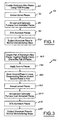
- Figure 1 is logic flow diagram for forming an aluminum alloy article using a solid state joining process according to one preferred embodiment of the present invention
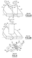
- Figure 2A is a perspective view of a friction stir welding tooling device used in Figure 1 according to a preferred embodiment of the present invention prior to the welding process;
- Figure 2B is a perspective view of a friction stir welding tooling device of Figure 2A after it has traversed along a portion of the joint line;
- Figure 3 is a logic flow diagram for forming an aluminum alloy article using a solid state joining process according to another preferred embodiment of the present invention.
- Figure 4 is a perspective view of a linear friction welding process used in Figure 3 according to a p referred embodiment of the present invention.
- logic flow diagram and diagram for producing an aluminum alloy article utilizing a solid state joining process is shown generally as 50.
- Step 60 The process starts in Step 60 by coupling together two parts 12, 14 of aluminum alloy using a conventional friction stir welding (“FSW”) process.
- FSW friction stir welding
- a cylindrical-shouldered friction stir welding tool 16 with a profiled threaded / unthreaded probe (nib) 18 is rotated at a constant speed and fed at a constant traverse rate into the joint line 20 between two parts 12, 14 of sheet or plate aluminum material, which are butted together.
- the parts 12, 14 have to be clamped rigidly onto a backing bar (not shown) in a manner that prevents the abutting joint faces 24, 26 from being forced apart while the nib 18 is placed at a position along the joint line 20.
- the nib 18 is then rotated at a constant rate (shown by arrow 34) as the tool 16 traverses along the joint line 20 (shown by arrow 32) from a first end 27 to a second end 29, therein generating frictional heat between the wear resistant welding tool shoulder 17 and nib 18, and the material of the work-pieces 12, 14.
- This heat along with the heat generated by the mechanical mixing process and the a diabatic heat within the material, cause the stirred materials to soften without reaching the melting point (hence cited a solid-state process), allowing the traversing of the tool 16 along the weld line 26.
- This is shown in Figure 2B.
- the welding 8of the material is facilitated by severe plastic deformation in the solid state involving dynamic recrystallization of the base aluminum material. The result is a joined aluminum-alloy material.
- the joined aluminum-alloy material is annealed at a temperature about 100-300 degrees Fahrenheit below the solutionizing temperature of the aluminum-alloy material.
- the annealing dissipates stored energy in the weld nugget so that the subsequent solution treating and aging steps do not cause secondary recrystallization and abnormal grain growth.
- the annealing is done at between 700 and 800 degrees Fahrenheit, and more preferably about 725 degrees Fahrenheit, for approximately 2 hours.
- the annealed material is air cooled to between room temperature and 250 degrees Fahrenheit.
- the annealed material may optionally be furnace cooled to about 500 degrees Fahrenheit prior to air-cooling.
- the annealed aluminum-alloy material is solution treated and aged (STA) in a conventional manner.
- STA solution treated and aged
- a typical STA treatment consisting of subjecting the aluminum-alloy material to a solutionizing temperature of between 850 and 1000 degrees, and more preferably about 890 degrees Fahrenheit, for about 1 hour, followed by a quenching step.
- the quenched material is then subsequent aged for about 4 hours at 250 degrees Fahrenheit and followed by a final aging step at 350 degrees Fahrenheit for about 8 hours.
- Step 100 the aluminum-alloy material is subjected to normal manufacturing steps associated with typical aerospace articles or components, such as fastening, chemical processing, and machining, including but not limited to cold-working and cold-forming, but not requiring the associated thermal or heat-treatment steps. These manufacturing steps form the part to its approximate final shape. The formed part is available for use in various articles of manufacture.
- FIG. 1 an alternative logic flow diagram for producing an aluminum alloy article utilizing a solid state joining process is shown generally as 150.
- two pieces 72, 74 of aluminum-alloy material are brought in close proximity with each other such that a respective face 76, 78 is substantially abut.
- the first piece 72 is rigidly fixed (clamped), while the second piece 74 is capable of linear reciprocating movement.
- Step 170 a force is applied to each respective piece as represented by arrows 92, 94. While a wide range of friction and forged pressure may be utilized, a preferred embodiment of the present invention utilizes a friction pressure of about 50 Newtons per square millimeter and a forge pressure of about 100 Newtons per square millimeter.
- Step 180 the second piece 74 is moved in a linear reciprocating motion, as shown by arrows 82, therein causing the faces 76, 78 to rub together.
- the linear reciprocating motion generates frictional heat and softening of the material at the weld interface 84 defined by the respective faces 76, 78, therein creating a weld nugget 86 of softened material.
- a portion of the weld nugget 8 6, or flash 88, is expelled from the weld interface 84 and trimmed or machined off.
- the reciprocating motion has a small amplitude of +/-1-3 mm, and more preferably +/- 2mm, at a frequency of between about 25-125 Hertz, and more preferably 40 Hertz.
- the shaped aluminum-alloy material is annealed.
- the annealing dissipates stored energy in the weld nugget so that the subsequent aging steps do not cause secondary recrystallization and abnormal grain growth.
- the annealing is done at about 100-300 degrees Fahrenheit below the solutionizing temperature of the aluminum-alloy material.
- the annealing is done preferably between 700 and 800 degrees, and more preferably at about 725 degrees Fahrenheit, for approximately 2 hours.
- the annealed material is air cooled to between room temperature and 250 degrees Fahrenheit.
- the annealed material may optionally be furnace cooled to about 500 degrees Fahrenheit prior to air-cooling.
- the annealed aluminum-alloy material is solution treated and aged in a conventional manner.
- a typical STA treatment consisting of subjecting the aluminum-alloy material to a solutionizing temperature of between 850 and 1000 degrees, and more preferably about 890 degrees Fahrenheit, for about 1 hour, followed by a quenching step.
- the quenched material is then subsequently aged for about 4 hours at 250 degrees Fahrenheit and followed by a final aging step at 350 degrees Fahrenheit for about 8 hours.
- Step 220 the aluminum-alloy material is subjected to normal manufacturing steps associated with typical aerospace articles or components, such as fastening, chemical processing, and machining, including but not limited to cold-working and cold-forming, but not requiring the associated thermal or heat-treatment steps. These manufacturing steps form the part to its approximate final shape. The formed part is available for use in various articles of manufacture.
- the present invention solves the problem of ductility reduction by conducting a thermal exposure treatment prior to solution heat treatment.
- This thermal exposure treatment, or post-weld annealing is done at a temperature below the solution heat treatment temperature and releases stored energy in the material.
- the material then does not have sufficient energy to cause recrystallization during the subsequent solution heat treatment process.
- the resultant material has a restored mechanical strength with only a minor, but acceptable, decrease in original ductility.
- R ow 1 indicates the mechanical properties of the alloy in its natural state.
- Row 2 describes the same mechanical properties for the aluminum alloy that has been joined by linear friction welding process and aged according to the prior art.
- Row 3 lists the mechanical properties where the alloy has been solution treated and aged after linear friction welding according to the prior art.
- Row 4 adds the annealing step that is the subject of the present invention prior to the solution treating and aging step.
- the present invention thus discloses a method to release the energy created during solid state joining processes such as LFW or FSW that is stored in the joined material.
- Thermal exposure at a temperature about 100 to 300 degrees Fahrenheit below the solution heat treatment temperature releases this stored energy. This temperature range is high enough to cause release of energy but low enough to avoid recrystallization and/or grain growth during subsequent solution heat treatment, quenching and aging.
- the aluminum alloy articles are joined with only a minor, but acceptable, decrease in the original ductility (typically between about 8 and 12%).
- the present invention is suitable for use in joining any types of metal or alloys utilizing a solid state process.
Landscapes
- Engineering & Computer Science (AREA)
- Mechanical Engineering (AREA)
- Chemical & Material Sciences (AREA)
- Physics & Mathematics (AREA)
- Thermal Sciences (AREA)
- Crystallography & Structural Chemistry (AREA)
- Materials Engineering (AREA)
- Metallurgy (AREA)
- Organic Chemistry (AREA)
- Pressure Welding/Diffusion-Bonding (AREA)
Abstract
Description
- The present invention generally relates to a method for preparing aluminum alloys and more specifically to a method to improve the properties of aluminum alloys processed by solid state joining.
- The worldwide acceptance of the economic benefits and high weld quality produced when using solid state joining techniques, including for example conventional rotary friction, to produce joints in round section metallic components has led to the development of other high weld quality processes for joining non-round and complex shaped parts.
- One newly developed process related to rotary friction welding, called linear friction welding ("LFW"), involves rubbing one component across the face of a second rigidly clamped component using a balanced, linear reciprocating motion. The linear reciprocating motion generates frictional heat and softening of the material at the weld interface that is expelled as flash. The two components are brought into perfect alignment towards the end of the weld cycle, and the welding force is maintained or increased to consolidate the joint. Machining or grinding can subsequently remove flash produced during the LFW process. The advantage to the LFW process over conventional rotary friction processes is that non-round or complex geometry components, such as aircraft engine blades to discs, can be welded using LFW.
- Friction stir welding ("FSW") is a solid-state process that uses a nonconsumable tool to join various types of metals. W hen a FSW rotating tool is inserted into and traverses through the materials, the tool plasticizes the materials and forces the materials to flow around the tool where they reconsolidate.
- While processes such as FSW and LFW have found popularity in various industries, the processes do have drawbacks. Age-work-, or strain-hardened metals exposed to the intense localized heat of welding tend to recrystallize and soften in the weld nugget because the strengthening precipitates have dissolved. The weld nugget can be strengthened by performing a post weld aging treatment that reprecipitates these strengthening precipitates. Welding also results in a heat-affected zone (HAZ) that surrounds the nugget. Whereas the nugget attains a high enough temperature to cause the precipitates to solutionize, the HAZ is heated to a lower temperature that causes the precipitate to grow in size and become less effective in strengthening. Post weld aging only further coarsens these precipitates.
- For example, both FSW and LFW reduce the strength of commonly used aluminum alloys (such as 7050 and 7055) by locally altering the microstructure and temper (In friction welded aluminum, for example, the friction welding process reduces the microstructure to a grain size of about 2-5 micrometers, which is much finer than the parent material). In fact, a strength degradation of about 25-30% typically occurs because of overaging in the HAZ. The nugget will initially be weaker, but will gradually strengthen by virtue of natural aging at room temperature..
- For example, as shown in Table 1 below, for one type of aluminum alloy (7050-T7451), the linear friction welding and subsequent aging resulted in a drop in allowable ultimate tensile stress (Ftu) of about 15%, a drop in the allowable tensile stress at which the material starts to yield in tension (Fty) of about 27%, and a drop in percent elongation of about 35-45%.
Condition Fty (ksi) Ftu (ksi) % Elongation 7050-T7451
Parent Metal63 74 7.5 7050-T7451
Linear Friction Welded and Aged46 63 4-5 - It is impossible or impractical to restore these strength properties by further mechanical processing, which severely limits the usefulness and applicability of these aluminum alloys in low-cost manufacturing process, especially for use in airframe components.
- One technique for recovering the strength of these aluminum alloys altered during the FSW or LFW process is to further heat treat the alloys using solution heat treating (at temperatures between about 900 and 1000 degrees Fahrenheit), quenching and aging (at temperatures ranging from about 250-350 degrees Fahrenheit). However, while the solution heat treatment step is necessary for the recovery of strength, it also results in excessive growth of the grains (from about 4 to 400 micrometers) of the weld itself and significantly degrades ductility, frequently to levels approaching zero.
- This excessive grain growth and loss of ductility is thought to occur because the friction welded blocks contain considerable amounts of stored energy, which causes secondary recrystallization and abnormal grain growth to occur during the solution treatment step.
- It is thus highly desirable to recover the strength of aluminum alloys lost during FSW, LFW or similar solid-state processes while preventing the resultant loss in ductility.
- The present invention solves the problem of ductility reduction by conducting a thermal exposure treatment prior to solution heat treatment. This thermal exposure treatment, or post-weld annealing, is done at a temperature below the solution heat treatment temperature and releases stored energy in the material. The material then does not have sufficient energy to cause recrystallization during the subsequent solution heat treatment process. The resultant material has a restored mechanical strength with only a minor, but acceptable, decrease in original ductility.
- While the process is ideally used to join aluminum alloys parts, the present invention is suitable for use in joining any types of metal.
- Other features, benefits and advantages of the present invention will become apparent from the following description of the invention, when viewed in accordance with the attached drawings and appended claims.
- Figure 1 is logic flow diagram for forming an aluminum alloy article using a solid state joining process according to one preferred embodiment of the present invention;
- Figure 2A is a perspective view of a friction stir welding tooling device used in Figure 1 according to a preferred embodiment of the present invention prior to the welding process;
- Figure 2B is a perspective view of a friction stir welding tooling device of Figure 2A after it has traversed along a portion of the joint line;
- Figure 3 is a logic flow diagram for forming an aluminum alloy article using a solid state joining process according to another preferred embodiment of the present invention;
- Figure 4 is a perspective view of a linear friction welding process used in Figure 3 according to a p referred embodiment of the present invention.
- Referring now to Figure 1, logic flow diagram and diagram for producing an aluminum alloy article utilizing a solid state joining process is shown generally as 50.
- The process starts in
Step 60 by coupling together twoparts - As best shown in Figures 2A and 2B, in a conventional FSW process, a cylindrical-shouldered friction
stir welding tool 16, with a profiled threaded / unthreaded probe (nib) 18 is rotated at a constant speed and fed at a constant traverse rate into thejoint line 20 between twoparts parts abutting joint faces nib 18 is placed at a position along thejoint line 20. Thenib 18 is then rotated at a constant rate (shown by arrow 34) as thetool 16 traverses along the joint line 20 (shown by arrow 32) from afirst end 27 to asecond end 29, therein generating frictional heat between the wear resistantwelding tool shoulder 17 andnib 18, and the material of the work-pieces tool 16 along theweld line 26. This is shown in Figure 2B. The welding 8of the material is facilitated by severe plastic deformation in the solid state involving dynamic recrystallization of the base aluminum material. The result is a joined aluminum-alloy material. - In
Step 70, the joined aluminum-alloy material is annealed at a temperature about 100-300 degrees Fahrenheit below the solutionizing temperature of the aluminum-alloy material. The annealing dissipates stored energy in the weld nugget so that the subsequent solution treating and aging steps do not cause secondary recrystallization and abnormal grain growth. For aluminum alloys such as 7050-T7451 parent metal, the annealing is done at between 700 and 800 degrees Fahrenheit, and more preferably about 725 degrees Fahrenheit, for approximately 2 hours. - In
Step 80, the annealed material is air cooled to between room temperature and 250 degrees Fahrenheit. As part of this process, the annealed material may optionally be furnace cooled to about 500 degrees Fahrenheit prior to air-cooling. - Next, in
Step 90, the annealed aluminum-alloy material is solution treated and aged (STA) in a conventional manner. For aluminum alloys such as 7050 and 7055, a typical STA treatment consisting of subjecting the aluminum-alloy material to a solutionizing temperature of between 850 and 1000 degrees, and more preferably about 890 degrees Fahrenheit, for about 1 hour, followed by a quenching step. The quenched material is then subsequent aged for about 4 hours at 250 degrees Fahrenheit and followed by a final aging step at 350 degrees Fahrenheit for about 8 hours. - In
Step 100, the aluminum-alloy material is subjected to normal manufacturing steps associated with typical aerospace articles or components, such as fastening, chemical processing, and machining, including but not limited to cold-working and cold-forming, but not requiring the associated thermal or heat-treatment steps. These manufacturing steps form the part to its approximate final shape. The formed part is available for use in various articles of manufacture. - Referring now to Figure 3, an alternative logic flow diagram for producing an aluminum alloy article utilizing a solid state joining process is shown generally as 150.
- Beginning with
Step 160, and shown best in Figure 4, twopieces respective face first piece 72 is rigidly fixed (clamped), while thesecond piece 74 is capable of linear reciprocating movement. - In
Step 170, a force is applied to each respective piece as represented byarrows 92, 94. While a wide range of friction and forged pressure may be utilized, a preferred embodiment of the present invention utilizes a friction pressure of about 50 Newtons per square millimeter and a forge pressure of about 100 Newtons per square millimeter. - In
Step 180, thesecond piece 74 is moved in a linear reciprocating motion, as shown byarrows 82, therein causing thefaces weld interface 84 defined by the respective faces 76, 78, therein creating aweld nugget 86 of softened material. A portion of the weld nugget 8 6, orflash 88, is expelled from theweld interface 84 and trimmed or machined off. For aluminum alloys using the preferred friction and forge pressures describe above, the reciprocating motion has a small amplitude of +/-1-3 mm, and more preferably +/- 2mm, at a frequency of between about 25-125 Hertz, and more preferably 40 Hertz. - In
step 190, the shaped aluminum-alloy material is annealed. The annealing dissipates stored energy in the weld nugget so that the subsequent aging steps do not cause secondary recrystallization and abnormal grain growth. The annealing is done at about 100-300 degrees Fahrenheit below the solutionizing temperature of the aluminum-alloy material. For aluminum alloys such as 7050, the annealing is done preferably between 700 and 800 degrees, and more preferably at about 725 degrees Fahrenheit, for approximately 2 hours. - In
Step 200, the annealed material is air cooled to between room temperature and 250 degrees Fahrenheit. As part of this process, the annealed material may optionally be furnace cooled to about 500 degrees Fahrenheit prior to air-cooling. - Next, in
Step 210, the annealed aluminum-alloy material is solution treated and aged in a conventional manner. For aluminum alloys such as 7050 and 7055, a typical STA treatment consisting of subjecting the aluminum-alloy material to a solutionizing temperature of between 850 and 1000 degrees, and more preferably about 890 degrees Fahrenheit, for about 1 hour, followed by a quenching step. The quenched material is then subsequently aged for about 4 hours at 250 degrees Fahrenheit and followed by a final aging step at 350 degrees Fahrenheit for about 8 hours. - In
Step 220, the aluminum-alloy material is subjected to normal manufacturing steps associated with typical aerospace articles or components, such as fastening, chemical processing, and machining, including but not limited to cold-working and cold-forming, but not requiring the associated thermal or heat-treatment steps. These manufacturing steps form the part to its approximate final shape. The formed part is available for use in various articles of manufacture. - The present invention solves the problem of ductility reduction by conducting a thermal exposure treatment prior to solution heat treatment. This thermal exposure treatment, or post-weld annealing, is done at a temperature below the solution heat treatment temperature and releases stored energy in the material. The material then does not have sufficient energy to cause recrystallization during the subsequent solution heat treatment process. The resultant material has a restored mechanical strength with only a minor, but acceptable, decrease in original ductility.
- For example, as shown in Table 2 below, a comparison is made of the mechanical properties for one type of aluminum alloy (7050-T7451). R ow 1 indicates the mechanical properties of the alloy in its natural state. Row 2 describes the same mechanical properties for the aluminum alloy that has been joined by linear friction welding process and aged according to the prior art. Row 3 lists the mechanical properties where the alloy has been solution treated and aged after linear friction welding according to the prior art. Row 4 adds the annealing step that is the subject of the present invention prior to the solution treating and aging step. The resultant mechanical properties are summarized in Table 2:
Condition Fty (ksi) Ftu (ksi) % Elongation 7050-T7451 blocks of Parent Metal 63 74 7.5 7050-T7451 blocks, linear friction welded and aged 46 63 4-5 7050-T7451 blocks, linear friction welded, and solution treated and aged 61 67 0.3 7050-T7451 blocks, linear friction welded, annealed for 2 hours at 725 degrees Fahrenheit, and solution treated and aged 70 75 3-7.5 - As Table 2 indicates, tensile strength tests across the welds and HAZ's where the post-weld annealing step was utilized, showed dramatic improvement. The nugget allowable ultimate tensile stress (Ftu) was 75 ksi and allowable tensile stress at which the material starts to yield in tension (Fty) was 70 ksi, while the percent elongation was between 3-7.5%, which is substantially similar to the starting material described in Row 1 and drastically improved from the typical aging process as shown in Row 2 and the typical solution treating and aging process as shown in Row 3. Thus, the annealing process allowed recovery of the mechanical properties lost during solid state joining process such as linear friction welding.
- The present invention thus discloses a method to release the energy created during solid state joining processes such as LFW or FSW that is stored in the joined material. Thermal exposure at a temperature about 100 to 300 degrees Fahrenheit below the solution heat treatment temperature releases this stored energy. This temperature range is high enough to cause release of energy but low enough to avoid recrystallization and/or grain growth during subsequent solution heat treatment, quenching and aging. The aluminum alloy articles are joined with only a minor, but acceptable, decrease in the original ductility (typically between about 8 and 12%).
- While the process is ideally used in conjunction with solid state process used to join aluminum alloys parts, the present invention is suitable for use in joining any types of metal or alloys utilizing a solid state process.
- While the invention has been described in terms of preferred embodiments, it will be understood, of course, that the invention is not limited thereto since modifications may be made by those skilled in the art, particularly in light of the foregoing teachings.
Claims (18)
- A method for improving the ductility of aluminum alloy articles formed by a solid state joining process, the method comprising releasing stored energy within the aluminum alloy material to substantially prevent recrystallization of the aluminum alloy material occurring in a subsequent solutionizing step.
- The method of claim 1, wherein releasing stored energy comprises annealing the aluminum alloy material at a first temperature for a first period of time, said first temperature being below the solutionizing temperature of the aluminum alloy material.
- A method for forming an aluminum-alloy article processed by solid state joining having improved ductility and elongation, the method comprising:forming an aluminum alloy material using a solid state joining process;annealing said aluminum alloy material to release stored energy within said aluminum alloy material;cooling said aluminum alloy material; andsolution treating and aging said aluminum alloy material.
- The method of claim 3, wherein annealing said aluminum alloy material comprises annealing said aluminum alloy material at between about 700 and 800 degrees Fahrenheit for a sufficient period of time to release stored energy within said aluminum alloy material.
- The method of claim 4, wherein annealing said aluminum alloy material comprises annealing said aluminum alloy material at about 725 degrees Fahrenheit for about 2 hours.
- The method of claim 3, 4 or 5, wherein cooling said aluminum alloy material comprises air-cooling said aluminum alloy material to between about room temperature and about 250 degrees Fahrenheit.
- The method of claim 6 further comprising furnace cooling said aluminum alloy material to about 500 degrees Fahrenheit prior to air-cooling said aluminum alloy material.
- The method of any of claims 2-7, wherein solution treating and aging said aluminum alloy material comprises:heating said aluminum alloy material to a solutionizing temperature;holding said aluminum alloy material at said solutionizing material for a predetermined amount of time;quenching said aluminum alloy material; andaging said aluminum alloy material at between about 250 and 350 degrees Fahrenheit.
- The method of claim 8, wherein aging said aluminum alloy material comprises aging said aluminum alloy material for about 4 hours at 250 degrees Fahrenheit followed by a final aging step at about 350 degrees Fahrenheit for about 8 hours.
- The method of claim 8 or 9, wherein heating said aluminum alloy material to a solutionizing temperature comprises heating said aluminum alloy material to between about 850 and 1000 degrees Fahrenheit.
- The method of claim 8, 9 or 10, wherein heating said aluminum alloy material to a solutionizing temperature and holding said aluminum alloy at said solutionizing temperature comprises heating said aluminum alloy material to about 890 degrees Fahrenheit for 1 hour.
- The method of any of claims 1-11, wherein forming an aluminum alloy material using a solid-state process comprises:providing a pair of pieces of an aluminum alloy material; andjoining one of said pair of aluminum alloy pieces the other of said pair of said pieces using a linear friction welding process.
- The method of claim 12, wherein joining one of said pair of aluminum alloy pieces to the other comprises:rigidly fixing a first one of said pair of aluminum alloy pieces;coupling a second one of said pair of aluminum alloy pieces such that a first face of said first one closely couples a second face of said second one;applying a first force on said second one of said pair of aluminum alloys such that said first face substantially abuts said second face, therein defining a weld interface;moving said second one of said pair of aluminum alloy pieces in a linear reciprocating fashion at a first frequency and a first amplitude such that said second face rubs against said first face and creates a weld nugget along said weld interface.
- The method according to claim 13, wherein said first force comprises a friction pressure of about 50 Newtons per square millimeter and further comprises a forge pressure of about 100 Newtons per square millimeter.
- The method of claim 13 or 14, wherein said first amplitude is between about +/- 1-3 millimeters.
- The method of claim 13, 14 or 15, wherein said first frequency is between about 25 and 125 Hertz.
- The method of any of claims 1-16, wherein forming an aluminum alloy material using a solid-state process comprises:providing a pair of pieces of an aluminum alloy material; andjoining one of said pair of aluminum alloy pieces the other of said pair of said pieces using a friction stir welding process.
- The method of claim 17, wherein joining one of said pair of aluminum alloy pieces to the other comprises:rigidly coupling said pair of aluminum alloy pieces such that a face of one of said pair of aluminum alloy pieces substantially abuts a corresponding face of an other of said pair of aluminum alloy pieces, wherein said face and said corresponding face define a joint line having a first end and a second end;coupling a friction stir welding device tool such that a nib is located along said joint line at a first end;rotating said nib at a constant rotational rate as said friction stir welding device traverses said joint line from said first end to said second end at a constant speed, wherein said constant rotational rate and said constant speed are sufficient to soften without melting said aluminum alloy pieces along said face and said corresponding face, therein forming a weld line along said softened face and said softened corresponding face; andcooling and recrystallizing said aluminum alloy pieces along said weld line to join said one of said aluminum alloy pieces to said other of said aluminum alloy pieces to form a joined aluminum alloy material.
Applications Claiming Priority (1)
| Application Number | Priority Date | Filing Date | Title |
|---|---|---|---|
| US10/939,528 US7614539B2 (en) | 2004-09-13 | 2004-09-13 | Method to improve properties of aluminum alloys processed by solid state joining |
Publications (2)
| Publication Number | Publication Date |
|---|---|
| EP1634670A1 true EP1634670A1 (en) | 2006-03-15 |
| EP1634670B1 EP1634670B1 (en) | 2010-06-09 |
Family
ID=35295518
Family Applications (1)
| Application Number | Title | Priority Date | Filing Date |
|---|---|---|---|
| EP05077074A Expired - Lifetime EP1634670B1 (en) | 2004-09-13 | 2005-09-12 | Method to improve properties of aluminium alloys processed by solid state joining |
Country Status (6)
| Country | Link |
|---|---|
| US (1) | US7614539B2 (en) |
| EP (1) | EP1634670B1 (en) |
| JP (1) | JP5258154B2 (en) |
| CN (1) | CN1789474A (en) |
| AT (1) | ATE470529T1 (en) |
| DE (1) | DE602005021732D1 (en) |
Cited By (4)
| Publication number | Priority date | Publication date | Assignee | Title |
|---|---|---|---|---|
| US10384299B2 (en) | 2013-06-26 | 2019-08-20 | Apple Inc. | Electron beam conditioning |
| CN112008226A (en) * | 2020-08-22 | 2020-12-01 | 张家港市固牌铝业有限公司 | Aluminum alloy profile plate welding process |
| CN114000070A (en) * | 2021-11-02 | 2022-02-01 | 上海电机学院 | Aluminum alloy hollow section, heat treatment method for inhibiting abnormal growth of longitudinal weld grains of aluminum alloy hollow section and application of aluminum alloy hollow section |
| CN114555844A (en) * | 2019-10-09 | 2022-05-27 | 株式会社Uacj | Welded structural member having excellent stress corrosion cracking resistance and method for producing same |
Families Citing this family (28)
| Publication number | Priority date | Publication date | Assignee | Title |
|---|---|---|---|---|
| US20070297935A1 (en) * | 2006-02-02 | 2007-12-27 | Timothy Langan | Stir processed cast aluminum-scandium structures and methods of making the same |
| CN102284785B (en) | 2006-10-02 | 2013-11-06 | 日本轻金属株式会社 | Joining method |
| JP4882004B2 (en) * | 2006-11-03 | 2012-02-22 | 株式会社東洋鋼鐵 | Manufacturing apparatus and manufacturing method for reinforcing frame for display panel using aluminum alloy extruded material |
| CN100424217C (en) * | 2006-11-30 | 2008-10-08 | 中国科学院长春应用化学研究所 | A kind of solid solution treatment method of heat-resistant magnesium-based rare earth alloy |
| US20080277036A1 (en) * | 2007-05-11 | 2008-11-13 | Luxfer Group Limited | Method for manufacturing tanks |
| US8852365B2 (en) * | 2009-01-07 | 2014-10-07 | The Boeing Company | Weldable high-strength aluminum alloys |
| FR2945464B1 (en) * | 2009-05-13 | 2012-03-23 | Alcan Rhenalu | PROCESS FOR WELDING ASSEMBLY OF ALUMINUM ALLOY PARTS. |
| US8323427B1 (en) | 2009-09-14 | 2012-12-04 | The Boeing Company | Engineered shapes from metallic alloys |
| US9090950B2 (en) * | 2010-10-13 | 2015-07-28 | The United States Of America As Represented By The Administrator Of The National Aeronautics And Space Administration | Abnormal grain growth suppression in aluminum alloys |
| JP5338884B2 (en) * | 2011-11-07 | 2013-11-13 | 日本軽金属株式会社 | Joining method |
| JP5508375B2 (en) * | 2011-11-07 | 2014-05-28 | 日本軽金属株式会社 | Joining method |
| JP5494692B2 (en) * | 2012-02-13 | 2014-05-21 | 日本軽金属株式会社 | Joining method |
| US9333702B2 (en) | 2012-11-30 | 2016-05-10 | The Boeing Company | Linear friction welding machine and associated method |
| EP3013514B1 (en) * | 2013-06-26 | 2018-08-22 | Constellium Issoire | Improved structural elements obtained by linear friction welding |
| EP3429793A1 (en) * | 2016-03-18 | 2019-01-23 | Aleris Rolled Products Germany GmbH | Method of manufacturing continuous cast aluminium alloy strip of variable width |
| US20190193194A1 (en) * | 2016-05-13 | 2019-06-27 | Hybond As | Solid State Extrusion and Bonding Method |
| AR106253A1 (en) * | 2016-10-04 | 2017-12-27 | Di Ciommo José Antonio | AIR CABLE FOR TRANSPORTATION OF ELECTRICAL ENERGY IN LOW AND MEDIUM VOLTAGE AND OF DIGITAL SIGNALS, OF CONCENTRIC ALUMINUM ALLOY CONDUCTORS CONTAINING WITHIN A TREPHILATED WIRE TREATMENT CABLE |
| JP6498651B2 (en) * | 2016-10-28 | 2019-04-10 | 日本軽金属株式会社 | Manufacturing method of hollow container |
| US10442030B2 (en) * | 2017-09-08 | 2019-10-15 | Seagate Technology Llc | Friction stir welding tool, related methods, and assemblies formed to include friction stir weld |
| KR102177001B1 (en) * | 2019-04-10 | 2020-11-10 | (주)케이디엠씨 | Material for manifold of pneumatic control device and method for preparing thereof |
| KR102415425B1 (en) * | 2019-09-23 | 2022-07-04 | 한국생산기술연구원 | Manufacturing method for aluminium alloy battery housing frame and the aluminum alloy battery housing frame |
| JP7681046B2 (en) * | 2020-07-09 | 2025-05-21 | ラム リサーチ コーポレーション | Friction Stir Processing for Corrosion Resistance |
| US11958126B2 (en) | 2020-10-06 | 2024-04-16 | GE Precision Healthcare LLC | Containers for retaining anesthetic agent and manufacturing methods thereof |
| KR102410369B1 (en) * | 2022-03-22 | 2022-06-22 | 국방과학연구소 | Friction Stir Welding Method for Al based Alloy |
| US12576455B2 (en) | 2022-10-20 | 2026-03-17 | Standex International Corporation | Friction stir welding process for large metallic components |
| CN117102654B (en) * | 2023-09-28 | 2024-10-29 | 南京工业大学 | Method for improving structural uniformity of friction stir additive manufacturing aluminum alloy |
| US20250050621A1 (en) * | 2023-11-06 | 2025-02-13 | Jimei University | High performance laminated aluminum alloy manufacturing method |
| CN117697118B (en) * | 2024-01-24 | 2026-08-04 | 集美大学 | Aging-reinforced aluminum alloy plate end surface friction stir processing method |
Citations (6)
| Publication number | Priority date | Publication date | Assignee | Title |
|---|---|---|---|---|
| EP0309087A1 (en) * | 1987-09-18 | 1989-03-29 | Imperial Chemical Industries Plc | Bonding metal components |
| EP0350329A1 (en) * | 1988-07-07 | 1990-01-10 | British Aerospace Public Limited Company | Process for producing composite metallic structures |
| US20030005852A1 (en) * | 1999-12-14 | 2003-01-09 | Hisanori Okamura | Structure and railway car |
| EP1285707A1 (en) * | 2001-08-22 | 2003-02-26 | The Boeing Company | Methods of manufacture of large diameter domes |
| US20040056075A1 (en) * | 2002-09-21 | 2004-03-25 | Iulian Gheorghe | Welded aluminum alloy structure |
| WO2004104258A1 (en) * | 2003-05-20 | 2004-12-02 | Pechiney Rhenalu | Method for welding by means of friction - agitation of aluminium alloy parts with heat treatment prior to welding |
Family Cites Families (9)
| Publication number | Priority date | Publication date | Assignee | Title |
|---|---|---|---|---|
| CS272098B1 (en) | 1988-07-08 | 1991-01-15 | Wichterle Otto | Double-convex lens from synthetic three-dimensional polymer and method of its preparation |
| JP3848707B2 (en) * | 1996-09-04 | 2006-11-22 | 日本特殊陶業株式会社 | Method for producing bonded body of age-hardening type aluminum alloy member and ceramic member |
| JP2001335873A (en) * | 2000-05-29 | 2001-12-04 | Sumitomo Light Metal Ind Ltd | Aluminum alloy bonding plate for automobile body, method of manufacturing the same, and vehicle body |
| JP2002088433A (en) * | 2000-09-14 | 2002-03-27 | Showa Denko Kk | Aluminum clad plate having convex tube and method of manufacturing the same |
| US6780525B2 (en) * | 2001-12-26 | 2004-08-24 | The Boeing Company | High strength friction stir welding |
| JP4008256B2 (en) * | 2002-02-15 | 2007-11-14 | 三菱重工業株式会社 | Method for manufacturing domes for use in aluminum alloy pressure vessels |
| JP4351025B2 (en) * | 2003-10-31 | 2009-10-28 | 住友軽金属工業株式会社 | Method for joining heat-treatable aluminum alloy materials |
| JP4707318B2 (en) * | 2003-11-05 | 2011-06-22 | 住友軽金属工業株式会社 | Aluminum alloy material joining method and press forming joining material |
| JP4323296B2 (en) * | 2003-11-26 | 2009-09-02 | 住友軽金属工業株式会社 | Method of joining heat-treatable aluminum alloy material and joining material for press forming |
-
2004
- 2004-09-13 US US10/939,528 patent/US7614539B2/en active Active
-
2005
- 2005-09-12 DE DE602005021732T patent/DE602005021732D1/en not_active Expired - Lifetime
- 2005-09-12 JP JP2005263692A patent/JP5258154B2/en not_active Expired - Lifetime
- 2005-09-12 AT AT05077074T patent/ATE470529T1/en not_active IP Right Cessation
- 2005-09-12 EP EP05077074A patent/EP1634670B1/en not_active Expired - Lifetime
- 2005-09-13 CN CNA2005101291217A patent/CN1789474A/en active Pending
Patent Citations (6)
| Publication number | Priority date | Publication date | Assignee | Title |
|---|---|---|---|---|
| EP0309087A1 (en) * | 1987-09-18 | 1989-03-29 | Imperial Chemical Industries Plc | Bonding metal components |
| EP0350329A1 (en) * | 1988-07-07 | 1990-01-10 | British Aerospace Public Limited Company | Process for producing composite metallic structures |
| US20030005852A1 (en) * | 1999-12-14 | 2003-01-09 | Hisanori Okamura | Structure and railway car |
| EP1285707A1 (en) * | 2001-08-22 | 2003-02-26 | The Boeing Company | Methods of manufacture of large diameter domes |
| US20040056075A1 (en) * | 2002-09-21 | 2004-03-25 | Iulian Gheorghe | Welded aluminum alloy structure |
| WO2004104258A1 (en) * | 2003-05-20 | 2004-12-02 | Pechiney Rhenalu | Method for welding by means of friction - agitation of aluminium alloy parts with heat treatment prior to welding |
Non-Patent Citations (1)
| Title |
|---|
| K.K. SANKARAN & R.J. LEDERICH: "Trends in Welding Research: Metallurgical Characterization of Friction Stir Welded 7050-T74 and C458-T8 Aluminium Alloys", 15 April 2002, THE MATERIALS INFORMATION SOCIETY, ASM INTERNATIONAL, PHOENIX- ARIZONA, U.S., XP009057375 * |
Cited By (4)
| Publication number | Priority date | Publication date | Assignee | Title |
|---|---|---|---|---|
| US10384299B2 (en) | 2013-06-26 | 2019-08-20 | Apple Inc. | Electron beam conditioning |
| CN114555844A (en) * | 2019-10-09 | 2022-05-27 | 株式会社Uacj | Welded structural member having excellent stress corrosion cracking resistance and method for producing same |
| CN112008226A (en) * | 2020-08-22 | 2020-12-01 | 张家港市固牌铝业有限公司 | Aluminum alloy profile plate welding process |
| CN114000070A (en) * | 2021-11-02 | 2022-02-01 | 上海电机学院 | Aluminum alloy hollow section, heat treatment method for inhibiting abnormal growth of longitudinal weld grains of aluminum alloy hollow section and application of aluminum alloy hollow section |
Also Published As
| Publication number | Publication date |
|---|---|
| JP2006075905A (en) | 2006-03-23 |
| US20060054252A1 (en) | 2006-03-16 |
| US7614539B2 (en) | 2009-11-10 |
| ATE470529T1 (en) | 2010-06-15 |
| EP1634670B1 (en) | 2010-06-09 |
| JP5258154B2 (en) | 2013-08-07 |
| CN1789474A (en) | 2006-06-21 |
| DE602005021732D1 (en) | 2010-07-22 |
Similar Documents
| Publication | Publication Date | Title |
|---|---|---|
| US7614539B2 (en) | Method to improve properties of aluminum alloys processed by solid state joining | |
| CN108778602B (en) | Low-temperature bonding method for metal materials and bonded structure | |
| US6638381B2 (en) | Method for preparing ultra-fine grain titanium and titanium-alloy articles and articles prepared thereby | |
| US7360676B2 (en) | Welded aluminum alloy structure | |
| CN107848065B (en) | Friction welding method | |
| US4606778A (en) | Joining method | |
| US6660106B1 (en) | Methods of manufacture of spin-forming blanks, particularly for fabrication of rocket domes | |
| JP2003236681A (en) | Structural assembly, method of manufacturing structural assembly, and friction stir welding apparatus and method | |
| US20120205014A1 (en) | Inertia friction weld of superalloy with enhanced post weld heat treatment | |
| US7490752B2 (en) | Manufacturing method for friction welded aluminum alloy parts | |
| US6802444B1 (en) | Heat treatment of friction stir welded 7X50 aluminum | |
| CN113369667A (en) | Welding joint of heterogeneous high-strength aluminum alloy and preparation method thereof | |
| EP4357063B1 (en) | Friction stir welding process for large metallic components | |
| JP4183177B2 (en) | Heat treated aluminum alloy bonding material with excellent ductility | |
| JP2003266182A (en) | Friction stir welding method for dissimilar metal materials | |
| JP4351025B2 (en) | Method for joining heat-treatable aluminum alloy materials | |
| Manjunath et al. | Investigation of effect of process parameters on friction stir welded dissimilar AA6061 T6 and AA7075 T651 | |
| CN118682419A (en) | A composite processing method for controlling the shape of friction stir welding joints | |
| Gulbudak et al. | The effect of process parameters on the material position of dissimilar friction stir welded AA2024-T3/5754-H22 joints | |
| JP2561785B2 (en) | Resin coating method on heat-treated aluminum material | |
| JP4323296B2 (en) | Method of joining heat-treatable aluminum alloy material and joining material for press forming | |
| EP4201578A1 (en) | Apparatus and method of forming countersinks and/or mouse holes in a stamped high strength aluminium sheet | |
| JPS58387A (en) | Manufacturing method of composite roll | |
| RU2063855C1 (en) | Process of manufacture of articles and semi-finished items from metals and alloys | |
| Tolephih et al. | Comparative study of the mechanical properties of (FS) and MIG welded joint in (AA7020-T6) aluminum alloy |
Legal Events
| Date | Code | Title | Description |
|---|---|---|---|
| PUAI | Public reference made under article 153(3) epc to a published international application that has entered the european phase |
Free format text: ORIGINAL CODE: 0009012 |
|
| AK | Designated contracting states |
Kind code of ref document: A1 Designated state(s): AT BE BG CH CY CZ DE DK EE ES FI FR GB GR HU IE IS IT LI LT LU LV MC NL PL PT RO SE SI SK TR |
|
| AX | Request for extension of the european patent |
Extension state: AL BA HR MK YU |
|
| 17P | Request for examination filed |
Effective date: 20060830 |
|
| AKX | Designation fees paid |
Designated state(s): AT BE BG CH CY CZ DE DK EE ES FI FR GB GR HU IE IS IT LI LT LU LV MC NL PL PT RO SE SI SK TR |
|
| 17Q | First examination report despatched |
Effective date: 20070622 |
|
| GRAP | Despatch of communication of intention to grant a patent |
Free format text: ORIGINAL CODE: EPIDOSNIGR1 |
|
| GRAS | Grant fee paid |
Free format text: ORIGINAL CODE: EPIDOSNIGR3 |
|
| GRAA | (expected) grant |
Free format text: ORIGINAL CODE: 0009210 |
|
| AK | Designated contracting states |
Kind code of ref document: B1 Designated state(s): AT BE BG CH CY CZ DE DK EE ES FI FR GB GR HU IE IS IT LI LT LU LV MC NL PL PT RO SE SI SK TR |
|
| REG | Reference to a national code |
Ref country code: CH Ref legal event code: EP |
|
| REG | Reference to a national code |
Ref country code: IE Ref legal event code: FG4D |
|
| REF | Corresponds to: |
Ref document number: 602005021732 Country of ref document: DE Date of ref document: 20100722 Kind code of ref document: P |
|
| REG | Reference to a national code |
Ref country code: NL Ref legal event code: VDEP Effective date: 20100609 |
|
| PG25 | Lapsed in a contracting state [announced via postgrant information from national office to epo] |
Ref country code: SE Free format text: LAPSE BECAUSE OF FAILURE TO SUBMIT A TRANSLATION OF THE DESCRIPTION OR TO PAY THE FEE WITHIN THE PRESCRIBED TIME-LIMIT Effective date: 20100609 Ref country code: LT Free format text: LAPSE BECAUSE OF FAILURE TO SUBMIT A TRANSLATION OF THE DESCRIPTION OR TO PAY THE FEE WITHIN THE PRESCRIBED TIME-LIMIT Effective date: 20100609 |
|
| LTIE | Lt: invalidation of european patent or patent extension |
Effective date: 20100609 |
|
| PG25 | Lapsed in a contracting state [announced via postgrant information from national office to epo] |
Ref country code: FI Free format text: LAPSE BECAUSE OF FAILURE TO SUBMIT A TRANSLATION OF THE DESCRIPTION OR TO PAY THE FEE WITHIN THE PRESCRIBED TIME-LIMIT Effective date: 20100609 Ref country code: AT Free format text: LAPSE BECAUSE OF FAILURE TO SUBMIT A TRANSLATION OF THE DESCRIPTION OR TO PAY THE FEE WITHIN THE PRESCRIBED TIME-LIMIT Effective date: 20100609 Ref country code: SI Free format text: LAPSE BECAUSE OF FAILURE TO SUBMIT A TRANSLATION OF THE DESCRIPTION OR TO PAY THE FEE WITHIN THE PRESCRIBED TIME-LIMIT Effective date: 20100609 Ref country code: LV Free format text: LAPSE BECAUSE OF FAILURE TO SUBMIT A TRANSLATION OF THE DESCRIPTION OR TO PAY THE FEE WITHIN THE PRESCRIBED TIME-LIMIT Effective date: 20100609 |
|
| PG25 | Lapsed in a contracting state [announced via postgrant information from national office to epo] |
Ref country code: GR Free format text: LAPSE BECAUSE OF FAILURE TO SUBMIT A TRANSLATION OF THE DESCRIPTION OR TO PAY THE FEE WITHIN THE PRESCRIBED TIME-LIMIT Effective date: 20100910 Ref country code: CY Free format text: LAPSE BECAUSE OF FAILURE TO SUBMIT A TRANSLATION OF THE DESCRIPTION OR TO PAY THE FEE WITHIN THE PRESCRIBED TIME-LIMIT Effective date: 20100609 Ref country code: PL Free format text: LAPSE BECAUSE OF FAILURE TO SUBMIT A TRANSLATION OF THE DESCRIPTION OR TO PAY THE FEE WITHIN THE PRESCRIBED TIME-LIMIT Effective date: 20100609 |
|
| PG25 | Lapsed in a contracting state [announced via postgrant information from national office to epo] |
Ref country code: EE Free format text: LAPSE BECAUSE OF FAILURE TO SUBMIT A TRANSLATION OF THE DESCRIPTION OR TO PAY THE FEE WITHIN THE PRESCRIBED TIME-LIMIT Effective date: 20100609 Ref country code: NL Free format text: LAPSE BECAUSE OF FAILURE TO SUBMIT A TRANSLATION OF THE DESCRIPTION OR TO PAY THE FEE WITHIN THE PRESCRIBED TIME-LIMIT Effective date: 20100609 |
|
| PG25 | Lapsed in a contracting state [announced via postgrant information from national office to epo] |
Ref country code: IS Free format text: LAPSE BECAUSE OF FAILURE TO SUBMIT A TRANSLATION OF THE DESCRIPTION OR TO PAY THE FEE WITHIN THE PRESCRIBED TIME-LIMIT Effective date: 20101009 Ref country code: RO Free format text: LAPSE BECAUSE OF FAILURE TO SUBMIT A TRANSLATION OF THE DESCRIPTION OR TO PAY THE FEE WITHIN THE PRESCRIBED TIME-LIMIT Effective date: 20100609 Ref country code: BE Free format text: LAPSE BECAUSE OF FAILURE TO SUBMIT A TRANSLATION OF THE DESCRIPTION OR TO PAY THE FEE WITHIN THE PRESCRIBED TIME-LIMIT Effective date: 20100609 Ref country code: CZ Free format text: LAPSE BECAUSE OF FAILURE TO SUBMIT A TRANSLATION OF THE DESCRIPTION OR TO PAY THE FEE WITHIN THE PRESCRIBED TIME-LIMIT Effective date: 20100609 Ref country code: SK Free format text: LAPSE BECAUSE OF FAILURE TO SUBMIT A TRANSLATION OF THE DESCRIPTION OR TO PAY THE FEE WITHIN THE PRESCRIBED TIME-LIMIT Effective date: 20100609 Ref country code: PT Free format text: LAPSE BECAUSE OF FAILURE TO SUBMIT A TRANSLATION OF THE DESCRIPTION OR TO PAY THE FEE WITHIN THE PRESCRIBED TIME-LIMIT Effective date: 20101011 |
|
| PLBI | Opposition filed |
Free format text: ORIGINAL CODE: 0009260 |
|
| PG25 | Lapsed in a contracting state [announced via postgrant information from national office to epo] |
Ref country code: IT Free format text: LAPSE BECAUSE OF FAILURE TO SUBMIT A TRANSLATION OF THE DESCRIPTION OR TO PAY THE FEE WITHIN THE PRESCRIBED TIME-LIMIT Effective date: 20100609 |
|
| PLAX | Notice of opposition and request to file observation + time limit sent |
Free format text: ORIGINAL CODE: EPIDOSNOBS2 |
|
| 26 | Opposition filed |
Opponent name: AIRBUS OPERATIONS GMBH/ AIRBUS FRANCE SAS/ A Effective date: 20110309 |
|
| PG25 | Lapsed in a contracting state [announced via postgrant information from national office to epo] |
Ref country code: MC Free format text: LAPSE BECAUSE OF NON-PAYMENT OF DUE FEES Effective date: 20100930 Ref country code: DK Free format text: LAPSE BECAUSE OF FAILURE TO SUBMIT A TRANSLATION OF THE DESCRIPTION OR TO PAY THE FEE WITHIN THE PRESCRIBED TIME-LIMIT Effective date: 20100609 |
|
| REG | Reference to a national code |
Ref country code: CH Ref legal event code: PL |
|
| REG | Reference to a national code |
Ref country code: DE Ref legal event code: R026 Ref document number: 602005021732 Country of ref document: DE Effective date: 20110309 |
|
| PG25 | Lapsed in a contracting state [announced via postgrant information from national office to epo] |
Ref country code: LI Free format text: LAPSE BECAUSE OF NON-PAYMENT OF DUE FEES Effective date: 20100930 Ref country code: IE Free format text: LAPSE BECAUSE OF NON-PAYMENT OF DUE FEES Effective date: 20100912 Ref country code: CH Free format text: LAPSE BECAUSE OF NON-PAYMENT OF DUE FEES Effective date: 20100930 |
|
| PLBB | Reply of patent proprietor to notice(s) of opposition received |
Free format text: ORIGINAL CODE: EPIDOSNOBS3 |
|
| PLAB | Opposition data, opponent's data or that of the opponent's representative modified |
Free format text: ORIGINAL CODE: 0009299OPPO |
|
| R26 | Opposition filed (corrected) |
Opponent name: AIRBUS OPERATIONS GMBH/ AIRBUS FRANCE SAS/ AIRBUS Effective date: 20110309 |
|
| PG25 | Lapsed in a contracting state [announced via postgrant information from national office to epo] |
Ref country code: LU Free format text: LAPSE BECAUSE OF NON-PAYMENT OF DUE FEES Effective date: 20100912 Ref country code: HU Free format text: LAPSE BECAUSE OF FAILURE TO SUBMIT A TRANSLATION OF THE DESCRIPTION OR TO PAY THE FEE WITHIN THE PRESCRIBED TIME-LIMIT Effective date: 20101210 Ref country code: BG Free format text: LAPSE BECAUSE OF FAILURE TO SUBMIT A TRANSLATION OF THE DESCRIPTION OR TO PAY THE FEE WITHIN THE PRESCRIBED TIME-LIMIT Effective date: 20100609 |
|
| PG25 | Lapsed in a contracting state [announced via postgrant information from national office to epo] |
Ref country code: TR Free format text: LAPSE BECAUSE OF FAILURE TO SUBMIT A TRANSLATION OF THE DESCRIPTION OR TO PAY THE FEE WITHIN THE PRESCRIBED TIME-LIMIT Effective date: 20100609 |
|
| PG25 | Lapsed in a contracting state [announced via postgrant information from national office to epo] |
Ref country code: BG Free format text: LAPSE BECAUSE OF FAILURE TO SUBMIT A TRANSLATION OF THE DESCRIPTION OR TO PAY THE FEE WITHIN THE PRESCRIBED TIME-LIMIT Effective date: 20100909 |
|
| PG25 | Lapsed in a contracting state [announced via postgrant information from national office to epo] |
Ref country code: ES Free format text: LAPSE BECAUSE OF FAILURE TO SUBMIT A TRANSLATION OF THE DESCRIPTION OR TO PAY THE FEE WITHIN THE PRESCRIBED TIME-LIMIT Effective date: 20100920 |
|
| REG | Reference to a national code |
Ref country code: DE Ref legal event code: R100 Ref document number: 602005021732 Country of ref document: DE |
|
| PLCK | Communication despatched that opposition was rejected |
Free format text: ORIGINAL CODE: EPIDOSNREJ1 |
|
| PLBN | Opposition rejected |
Free format text: ORIGINAL CODE: 0009273 |
|
| STAA | Information on the status of an ep patent application or granted ep patent |
Free format text: STATUS: OPPOSITION REJECTED |
|
| 27O | Opposition rejected |
Effective date: 20150316 |
|
| REG | Reference to a national code |
Ref country code: FR Ref legal event code: PLFP Year of fee payment: 12 |
|
| REG | Reference to a national code |
Ref country code: FR Ref legal event code: PLFP Year of fee payment: 13 |
|
| REG | Reference to a national code |
Ref country code: FR Ref legal event code: PLFP Year of fee payment: 14 |
|
| P01 | Opt-out of the competence of the unified patent court (upc) registered |
Effective date: 20230503 |
|
| PGFP | Annual fee paid to national office [announced via postgrant information from national office to epo] |
Ref country code: DE Payment date: 20240927 Year of fee payment: 20 |
|
| PGFP | Annual fee paid to national office [announced via postgrant information from national office to epo] |
Ref country code: GB Payment date: 20240927 Year of fee payment: 20 |
|
| PGFP | Annual fee paid to national office [announced via postgrant information from national office to epo] |
Ref country code: FR Payment date: 20240925 Year of fee payment: 20 |
|
| REG | Reference to a national code |
Ref country code: DE Ref legal event code: R071 Ref document number: 602005021732 Country of ref document: DE |
|
| REG | Reference to a national code |
Ref country code: GB Ref legal event code: PE20 Expiry date: 20250911 |