EP1634251B1 - Coin dispensing apparatus - Google Patents
Coin dispensing apparatus Download PDFInfo
- Publication number
- EP1634251B1 EP1634251B1 EP04736989.7A EP04736989A EP1634251B1 EP 1634251 B1 EP1634251 B1 EP 1634251B1 EP 04736989 A EP04736989 A EP 04736989A EP 1634251 B1 EP1634251 B1 EP 1634251B1
- Authority
- EP
- European Patent Office
- Prior art keywords
- coin
- ejector device
- coins
- outlet
- ejected
- Prior art date
- Legal status (The legal status is an assumption and is not a legal conclusion. Google has not performed a legal analysis and makes no representation as to the accuracy of the status listed.)
- Expired - Lifetime
Links
- 230000003287 optical effect Effects 0.000 claims description 18
- 230000005855 radiation Effects 0.000 claims description 3
- 230000002093 peripheral effect Effects 0.000 claims 1
- 230000008901 benefit Effects 0.000 description 2
- 230000008859 change Effects 0.000 description 2
- 238000000034 method Methods 0.000 description 2
- 230000008569 process Effects 0.000 description 2
- 230000009471 action Effects 0.000 description 1
- 230000006835 compression Effects 0.000 description 1
- 238000007906 compression Methods 0.000 description 1
- 238000010276 construction Methods 0.000 description 1
- 230000001419 dependent effect Effects 0.000 description 1
- 238000010586 diagram Methods 0.000 description 1
- 230000000694 effects Effects 0.000 description 1
- 230000009467 reduction Effects 0.000 description 1
- 238000009877 rendering Methods 0.000 description 1
Images




Classifications
-
- G—PHYSICS
- G07—CHECKING-DEVICES
- G07D—HANDLING OF COINS OR VALUABLE PAPERS, e.g. TESTING, SORTING BY DENOMINATIONS, COUNTING, DISPENSING, CHANGING OR DEPOSITING
- G07D9/00—Counting coins; Handling of coins not provided for in the other groups of this subclass
- G07D9/008—Feeding coins from bulk
Definitions
- This invention relates to a coin dispensing apparatus and has particular but not exclusive application to a hopper for dispensing coins in gaming and vending machines.
- coin dispensing apparatus in the form of a hopper has been used to dispense coins in gaming machines to provide a prize and also to dispense coins in vending machines to provide change.
- An example is the Compact Hopper manufactured by Money Controls Limited. Reference is also directed to EP-A-0266021 .
- the hopper is typically fed with coins from a coin acceptor.
- a disc-like rotary member has a number of coin receptacles that receive the coins and a motor rotates the rotary member so as to move coins in the receptacles along an annular coin path so that they can be ejected successively from the receptacles through a coin outlet disposed to one side of the path.
- a spring loaded ejector device ejects coins from the receptacles to the coin outlet.
- the ejector device is positioned so that it is moved from a coin engaging position against the force of the spring to a discharge position by a coin as it moves along the annular path to be ejected from the coin outlet, so that as the coin comes aligned with the outlet, the force of the spring is released and the ejector device moves from a discharge position so as to eject the coin through the outlet and thence to the coin engaging position for the next approaching coin to be ejected.
- An optical counting device has been used to count the coins as they are ejected from the outlet so that the correct payout or change can be dispensed. Hitherto, the counting device has comprised an optical emitter and detector at the coin outlet so that each dispensed coin breaks the optical path between the emitter and the detector to provide a coin count signal.
- a problem with this conventional counting arrangement is that the optical emitter and detector are mounted on the exterior of the apparatus rendering them vulnerable to attack by fraudsters and vandals.
- a fraudster may insert a knife blade or other similar instrument through the conventional payout opening of the vending or gaming machine and physically break off the optical counting device.
- the present invention seeks to provide a coin dispensing apparatus with an improved counting arrangement which is less prone to fraudulent operation and vandalisation.
- the invention provides coin dispensing apparatus comprising a coin source, a rotary member with a plurality of coin receptacles to receive coins from the coin source, a motor to rotate the rotary member so as to move coins in the receptacles along an annular coin path, a coin outlet disposed to one side of the coin path, and a movable ejector device to eject coins from the receptacles through the coin outlet, a body within which the motor and the ejector device are mounted, a flat surface on the body to provide said path for coins from the source, the ejector device being positioned so that it is moved to from a coin engaging position to a discharge position by a coin as it moves along the annular path to be ejected through the coin outlet, drive means operable to drive the ejector device from the discharge position to eject the coin through the outlet and thence to the coin engaging position for a next approaching coin to be ejected, and counting means to count coins ejected through the
- the detector Since the detector is housed within the body of the coin dispensing apparatus, the arrangement is less accessible to fraudsters and vandals. More particularly, if a vandal jams the operation of the ejector device to confuse the counting means, no coins will be ejected and so the fraudster will be defeated.
- the ejector device may comprise first and second coin engaging members movable independently between said coin engaging position and said discharge position.
- the ejector device may comprise at least one slider member movable between the coin engaging position and the discharge position.
- the coin dispensing apparatus comprises a body member 1, a hopper 2, and a disc-like rotary member 3 mounted on the body member 1.
- the rotary member 3 is rotated in the direction of arrow A by an electric motor 4 mounted within the body member 1, through a reduction gear train 5.
- An example of the gear train 5 is described in more detail in EP-A-0266021 .
- coins fall into the hopper 2, for example from a coin acceptor, so that the hopper acts as a coin source and feeds coins into circular apertures 6 in the rotary member 3.
- the coins slide on inclined side wall 7 of the body member 1 which has an annular upper surface 8 bounded by a circular side wall 9 around the circular edge of the rotary member 3.
- a coin outlet 10 is provided in the side wall 9.
- a coin ejector device 11 in the form of a pivoted fork member has first and second coin engaging members 11a, 11b protruding through respective openings 12a, 12b in the inclined wall 7 of the body member.
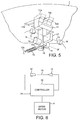
- the ejector device 11 is shown in more detail in Figure 5 and comprises an arm 13 which includes integral lugs 14 that are pivotally mounted in corresponding receptacles within the body member 1 (not shown) so that the device 11 can turn about axis B-B'.
- a tension spring 15 is mounted at one end 15a on lug 16 on the arm 13, and at the other end 15b on the body member 1 by a mounting (not shown).
- the ejector device 11 can move from a coin engaging position shown in Figure 5 , with the first and second coin engaging members 11a, 11b at one of end of each of the openings 12a, 12b, to a coin dispensing position when an approaching coin on the surface 8 moves the coin engaging members 11a, 11b, towards the other end of the openings 12a, 12b, against the force of spring 15.
- an optical emitter and detector 17, 18 which may operate with any suitable optical wavelength including non-visible radiation such as infra-red or ultra-violet.
- an infra-red detector is used.
- the optical path 19 between the emitter and detector 17, 18 is interrupted by an arm 13' on the ejector device 11. In the coin engaging position shown in Figure 5 , the arm 13' interrupts the optical path 19 so that detector 18 detects no radiation from the emitter 17.
- the device 11 rotates about axis B-B' to the coin dispensing position, in which the coin engaging members 11a, 11b are moved to the opposite ends of the openings 12a, 12b, the optical path 19 is opened as a result, detector 18 produces an electrical output.
- the ejector device 11 rotates back and forth for each coin ejection and so a coin count signal is developed by the detector 18.
- FIG. 6 illustrates the electrical circuitry of the apparatus.
- a controller 20 receives the count signal from the detector 18 and also controls energisation of the emitter 17.
- a pay instruction 21 which may comprise an instruction to pay out a predetermined number of coins, is received by the controller 20, for example from a control unit (not shown) associated with a vending or gaming machine.
- the controller 20 energises the drive motor 4 so as to rotate member 3 until the number of count signals developed by detector 18 corresponds to the coin number given in the pay instruction 21.
- Figure 7A shows a coin C which has passed through aperture 6' in the rotary member 3 so as to sit in the receptacle on the underside of the member 3, in engagement with annular surface 8 on the body member 1.
- the underside of the rotary member 3 has a hollowed out annular portion 3a of thickness corresponding to that of one coin.
- the coin C abuts a lug 3b that extends across the thickness of the receptacle onto the surface 8. This arrangement is described in more detail in our EP-A-0266021 .
- the coin C is swept towards the coin ejector device 11 as shown in Figure 7B .
- the ejector device is in its coin engaging position corresponding to the arrangement of Figure 5 , in which the spring 15 biases the coin engaging members 11a, 11b to one end of the openings 12a, 12b.
- the coin C engages the first and second members 11a, 11b as the motor 4 rotates member 3 in the direction of arrow A.
- the coin ejection process produces a back and forth rocking motion of the ejector member 11 which modulates the optical path 19 between the emitter and detector 17, 18 thereby producing a coin count signal each time the coin is ejected.
- the coin count signals are counted by the controller 20 and compared with the payout instruction 21 so as to determine when a predetermined payout has been effected.
- the motor 4 is then de-energised in order to prevent overpayment.
- An advantage of the described counting system is that the optical detectors are mounted entirely within the body member 1 making it difficult for a fraudster to tamper with them. In the event that the fraudster attempts to tamper with the ejector member 11, this also most certainly with produce a disabling effect on the entire coin dispensing apparatus thereby defeating the object of the fraudster.
- the coin may continue to rotate past the coin ejecting member, driving it further along the openings 12a, 12b so that the coin engaging members rotate downwardly below the surface 8 and allow the coin to pass around in a complete rotation and thereby avoid jamming of the apparatus.
- FIG. 8 and 9 an alternative ejector device for the dispensing apparatus is shown which is generally similar to the arrangement of Figure 5 but in which the coin engaging members 11a, 11b are independently rotatable about the axis B-B'.
- Each coin engaging member 11a, 11b has a respective arm 13a, 13b biased by an individual spring 15a, 15b.
- FIG 9B movement of either of the arms 13a, 13b from the coin engaging position to the coin dispensing position will result in interruption of the optical path 19 between the optical emitter and detector 17, 18 thereby producing a count signal. This can also be seen from Figure 8 .
- the advantage of the independently movable members 11a, 11b is that a more even pressure is allied to the coin C during the ejection process since both of them can engage the perimeter of the coin and produce an individual flicking action to eject the coin through the outlet 10.
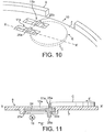
- FIGs 10 and 11 Another embodiment of ejector member is shown in Figures 10 and 11 , in which the coin engaging members 11a, 11 bare slidably mounted.
- the coin engaging member 11a is shown in sectional view in Figure 11 and comprises a slider member 22a received in an integrally moulded slot 23a in the wall 7 that provides the annular surface 8 over which the coins C slide in use.
- the slider member 22a is biased by a compression spring 24a into the coin engaging position shown in Figure 11 .
- the slider member 22a can slide along the slot 23a in the direction of arrow D towards the coin dispensing position.
- the slider member 22a has an upstanding coin engaging part 25a which engages the edge of coin C when it is moved in the direction arrow E by the rotary member 3 (not shown in this Figure).
- the slider also includes a downwardly dependent arm 26a which interrupts the optical path 19 between the emitter and detector 17, 18 (not shown) to produce the coin counting signal each time.
- the second coin engaging member 11b has an identical construction to the arrangement of Figure 11 so that when either of the members 25a, 25b move from the coin engaging position to the coin dispensing position, the optical beam 19 is interrupted and the coin counting signal is produced.
- coin includes tokens and other coin-like items having an attributable monetary value.
Landscapes
- Physics & Mathematics (AREA)
- General Physics & Mathematics (AREA)
- Slot Machines And Peripheral Devices (AREA)
- Control Of Vending Devices And Auxiliary Devices For Vending Devices (AREA)
- Filling Or Emptying Of Bunkers, Hoppers, And Tanks (AREA)
Description
- This invention relates to a coin dispensing apparatus and has particular but not exclusive application to a hopper for dispensing coins in gaming and vending machines.
- Hitherto, coin dispensing apparatus in the form of a hopper has been used to dispense coins in gaming machines to provide a prize and also to dispense coins in vending machines to provide change. An example is the Compact Hopper manufactured by Money Controls Limited. Reference is also directed to
EP-A-0266021 . - The hopper is typically fed with coins from a coin acceptor. A disc-like rotary member has a number of coin receptacles that receive the coins and a motor rotates the rotary member so as to move coins in the receptacles along an annular coin path so that they can be ejected successively from the receptacles through a coin outlet disposed to one side of the path. A spring loaded ejector device ejects coins from the receptacles to the coin outlet. The ejector device is positioned so that it is moved from a coin engaging position against the force of the spring to a discharge position by a coin as it moves along the annular path to be ejected from the coin outlet, so that as the coin comes aligned with the outlet, the force of the spring is released and the ejector device moves from a discharge position so as to eject the coin through the outlet and thence to the coin engaging position for the next approaching coin to be ejected.
An optical counting device has been used to count the coins as they are ejected from the outlet so that the correct payout or change can be dispensed. Hitherto, the counting device has comprised an optical emitter and detector at the coin outlet so that each dispensed coin breaks the optical path between the emitter and the detector to provide a coin count signal. - Document
US2002/0061724 discloses a disk for a coin hopper, the disk having pins to exit the rotated coins towards the coin exit. - However, a problem with this conventional counting arrangement is that the optical emitter and detector are mounted on the exterior of the apparatus rendering them vulnerable to attack by fraudsters and vandals. For example, a fraudster may insert a knife blade or other similar instrument through the conventional payout opening of the vending or gaming machine and physically break off the optical counting device. As a result, there is a risk that the dispensing apparatus will erroneously dispense all of the coins in the hopper. The present invention seeks to provide a coin dispensing apparatus with an improved counting arrangement which is less prone to fraudulent operation and vandalisation.
- The invention provides coin dispensing apparatus comprising a coin source, a rotary member with a plurality of coin receptacles to receive coins from the coin source, a motor to rotate the rotary member so as to move coins in the receptacles along an annular coin path, a coin outlet disposed to one side of the coin path, and a movable ejector device to eject coins from the receptacles through the coin outlet, a body within which the motor and the ejector device are mounted, a flat surface on the body to provide said path for coins from the source, the ejector device being positioned so that it is moved to from a coin engaging position to a discharge position by a coin as it moves along the annular path to be ejected through the coin outlet, drive means operable to drive the ejector device from the discharge position to eject the coin through the outlet and thence to the coin engaging position for a next approaching coin to be ejected, and counting means to count coins ejected through the outlet wherein the surface has an opening therein through which the ejector device protrudes from within the body beneath the surface into the path to eject coins, the counting means includes a detector within the body to detect movement of the ejector device that occurs within the body beneath the flat surface, for counting the ejected coins.
- Since the detector is housed within the body of the coin dispensing apparatus, the arrangement is less accessible to fraudsters and vandals. More particularly, if a vandal jams the operation of the ejector device to confuse the counting means, no coins will be ejected and so the fraudster will be defeated.
- The ejector device may comprise first and second coin engaging members movable independently between said coin engaging position and said discharge position.
- Furthermore, the ejector device may comprise at least one slider member movable between the coin engaging position and the discharge position.
- In order that the invention may be more fully understood embodiments thereof will now be described by way of example with reference to the accompanying drawings in which:
-
Figure 1 is an exploded perspective view from above and one side of a coin dispensing apparatus according to the invention; -
Figure 2 is a front view of the apparatus shown inFigure 1 ; -
Figure 3 is a rear view of the apparatus; -
Figure 4 is a side view of the apparatus; -
Figure 5 is a schematic perspective view of the ejector member of the apparatus; -
Figure 6 is a schematic block diagram of electrical coin counting circuitry; -
Figures 7A - E illustrate successive stages in the ejection of a coin from the coin dispensing apparatus; -
Figure 8 is a schematic plan view of an alternative embodiment of the ejector device in which the two coin engaging members are independently movable; -
Figure 9A and B are schematic illustrations of the ejector member ofFigure 8 in different operative configurations; -
Figure 10 is a schematic perspective view of another embodiment of ejector device for use in the apparatus; and -
Figure 11 is a sectional of the configuration shown inFigure 10 taken along the line X - X'. - Referring to
Figures 1 to 4 , the coin dispensing apparatus comprises abody member 1, ahopper 2, and a disc-likerotary member 3 mounted on thebody member 1. Therotary member 3 is rotated in the direction of arrow A by anelectric motor 4 mounted within thebody member 1, through areduction gear train 5. An example of thegear train 5 is described in more detail inEP-A-0266021 . - In use, coins fall into the
hopper 2, for example from a coin acceptor, so that the hopper acts as a coin source and feeds coins intocircular apertures 6 in therotary member 3. The coins slide oninclined side wall 7 of thebody member 1 which has an annularupper surface 8 bounded by acircular side wall 9 around the circular edge of therotary member 3. Acoin outlet 10 is provided in theside wall 9. - A
coin ejector device 11 in the form of a pivoted fork member has first and secondcoin engaging members respective openings inclined wall 7 of the body member. - The
ejector device 11 is shown in more detail inFigure 5 and comprises anarm 13 which includesintegral lugs 14 that are pivotally mounted in corresponding receptacles within the body member 1 (not shown) so that thedevice 11 can turn about axis B-B'. - A
tension spring 15 is mounted at oneend 15a onlug 16 on thearm 13, and at theother end 15b on thebody member 1 by a mounting (not shown). - The
ejector device 11 can move from a coin engaging position shown inFigure 5 , with the first and secondcoin engaging members openings surface 8 moves thecoin engaging members openings spring 15. - In order to count coins, movement of the
ejector device 11 between the coin engaging and coin dispensing positions is detected using an optical emitter anddetector optical path 19 between the emitter anddetector ejector device 11. In the coin engaging position shown inFigure 5 , the arm 13' interrupts theoptical path 19 so thatdetector 18 detects no radiation from theemitter 17. However, when thedevice 11 rotates about axis B-B' to the coin dispensing position, in which thecoin engaging members openings optical path 19 is opened as a result,detector 18 produces an electrical output. As will be explained later, theejector device 11 rotates back and forth for each coin ejection and so a coin count signal is developed by thedetector 18. -
Figure 6 illustrates the electrical circuitry of the apparatus. Acontroller 20 receives the count signal from thedetector 18 and also controls energisation of theemitter 17. When an instruction is received to pay out coins, apay instruction 21, which may comprise an instruction to pay out a predetermined number of coins, is received by thecontroller 20, for example from a control unit (not shown) associated with a vending or gaming machine. In use, thecontroller 20 energises thedrive motor 4 so as to rotatemember 3 until the number of count signals developed bydetector 18 corresponds to the coin number given in thepay instruction 21. - Operation of the device will now be described in more detail with reference to
Figures 7A - 7E .Figure 7A shows a coin C which has passed through aperture 6' in therotary member 3 so as to sit in the receptacle on the underside of themember 3, in engagement withannular surface 8 on thebody member 1. The underside of therotary member 3 has a hollowed outannular portion 3a of thickness corresponding to that of one coin. The coin C abuts alug 3b that extends across the thickness of the receptacle onto thesurface 8. This arrangement is described in more detail in ourEP-A-0266021 . As themotor 4 rotates the disc-like member 3 in the direction of arrow A, the coin C is swept towards thecoin ejector device 11 as shown inFigure 7B . InFigures 7A and 7B , the ejector device is in its coin engaging position corresponding to the arrangement ofFigure 5 , in which thespring 15 biases thecoin engaging members openings Figure 7B , the coin C engages the first andsecond members motor 4 rotatesmember 3 in the direction of arrow A. - Then, as shown in
Figure 7C , continued rotation of themember 3 causes the coin C to push back themember 11 against the bias of thespring 15, into the coin dispensing position so that, as shown inFigure 7D , when the coin C becomes aligned with thecoin outlet 10, the spring bias drives thecoin engaging members Figure 7E , themember 11 returns to the initial, coin engaging position and the coin C is paid out through thecoin outlet 10. - Thus, the coin ejection process produces a back and forth rocking motion of the
ejector member 11 which modulates theoptical path 19 between the emitter anddetector Figure 6 , the coin count signals are counted by thecontroller 20 and compared with thepayout instruction 21 so as to determine when a predetermined payout has been effected. Themotor 4 is then de-energised in order to prevent overpayment. - An advantage of the described counting system is that the optical detectors are mounted entirely within the
body member 1 making it difficult for a fraudster to tamper with them. In the event that the fraudster attempts to tamper with theejector member 11, this also most certainly with produce a disabling effect on the entire coin dispensing apparatus thereby defeating the object of the fraudster. - In the event of a coin jam, the coin may continue to rotate past the coin ejecting member, driving it further along the
openings surface 8 and allow the coin to pass around in a complete rotation and thereby avoid jamming of the apparatus. - Referring now to
Figure 8 and9 , an alternative ejector device for the dispensing apparatus is shown which is generally similar to the arrangement ofFigure 5 but in which thecoin engaging members coin engaging member respective arm individual spring Figure 9B , movement of either of thearms optical path 19 between the optical emitter anddetector Figure 8 . The advantage of the independentlymovable members outlet 10. Another embodiment of ejector member is shown inFigures 10 and 11 , in which thecoin engaging members coin engaging member 11a is shown in sectional view inFigure 11 and comprises aslider member 22a received in an integrally mouldedslot 23a in thewall 7 that provides theannular surface 8 over which the coins C slide in use. Theslider member 22a is biased by a compression spring 24a into the coin engaging position shown inFigure 11 . Theslider member 22a can slide along theslot 23a in the direction of arrow D towards the coin dispensing position. Theslider member 22a has an upstandingcoin engaging part 25a which engages the edge of coin C when it is moved in the direction arrow E by the rotary member 3 (not shown in this Figure). The slider also includes a downwardlydependent arm 26a which interrupts theoptical path 19 between the emitter anddetector 17, 18 (not shown) to produce the coin counting signal each time. It will be understood that the secondcoin engaging member 11b has an identical construction to the arrangement ofFigure 11 so that when either of themembers optical beam 19 is interrupted and the coin counting signal is produced. - As used herein, the term coin includes tokens and other coin-like items having an attributable monetary value.
Claims (10)
- Coin dispensing apparatus comprising a coin source (2), a rotary member (3) with a plurality of coin receptacles (6) to receive coins from the coin source, a motor (4) to rotate the rotary member so as to move coins in the receptacles along an annular coin path, a coin outlet (10) disposed to one side of the coin path, and a movable ejector device (11) to eject coins from the receptacles through the coin outlet, a body (1) within which the motor and the ejector device are mounted, a flat surface (7) on the body to provide said path for coins from the source, the ejector device being positioned so that it is moved from a coin engaging position to a discharge position by a coin as it moves along the annular path to be ejected through the coin outlet, drive means (15) operable to drive the ejector device from the discharge position to eject the coin through the outlet and thence to the coin engaging position for a next approaching coin to be ejected, and counting means (17, 18, 21) to count coins ejected through the outlet characterised in that the surface (7) has an opening (12a, 12b) therein through which the ejector device protrudes from within the body beneath the surface into the path to eject coins, and the counting means includes a detector (18) within the body to detect movement of the ejector device that occurs within the body beneath the flat surface (7), for counting the ejected coins..
- Apparatus according to claim 1 wherein the counting means comprises an optical emitter (17) and an optical detector (18), movement of the ejector device (11) within the body (1) controlling passage of the radiation from the emitter to the detector in response to each coin ejected through the coin outlet whereby the detector provides a count signal corresponding to the ejected coins.
- Apparatus according to claim 1 or 2 wherein the drive means comprises a spring (15) urging the ejector device from the discharge position towards the coin engaging position.
- Apparatus according to any preceding claim wherein the flat surface has an annular periphery bounded by a peripheral wall (9) having the coin outlet (10) therein.
- Apparatus according to claim 4 wherein the coin source comprises a hopper (2) mounted on the body.
- Apparatus according to any preceding claim wherein the ejector device comprises first and second coin engaging members (11 a, 11b) movable between said coin engaging position and said discharge position.
- Apparatus according to claim 6 wherein the coin engaging members are mounted for movement in unison.
- Apparatus according to claim 6 wherein the coin engaging members are mounted for movement independently.
- Apparatus according to any preceding claim wherein the ejector device comprises at least one an arm (13a, 13b) configured to turn between said coin engaging position and said discharge position, and the counting means is operable to detect the turning of the arm in response to each coin ejected through the coin outlet.
- Apparatus according to any one of claims 1 to 8 wherein the ejector device comprises at least one slider member (22a, 22b) movable between the coin engaging position and the discharge position.
Applications Claiming Priority (2)
| Application Number | Priority Date | Filing Date | Title |
|---|---|---|---|
| GB0314323A GB2402934A (en) | 2003-06-19 | 2003-06-19 | Coin dispensing apparatus |
| PCT/GB2004/002587 WO2004114228A1 (en) | 2003-06-19 | 2004-06-17 | Coin dispensing apparatus |
Publications (2)
| Publication Number | Publication Date |
|---|---|
| EP1634251A1 EP1634251A1 (en) | 2006-03-15 |
| EP1634251B1 true EP1634251B1 (en) | 2016-07-20 |
Family
ID=27636943
Family Applications (1)
| Application Number | Title | Priority Date | Filing Date |
|---|---|---|---|
| EP04736989.7A Expired - Lifetime EP1634251B1 (en) | 2003-06-19 | 2004-06-17 | Coin dispensing apparatus |
Country Status (8)
| Country | Link |
|---|---|
| US (1) | US20070259613A1 (en) |
| EP (1) | EP1634251B1 (en) |
| JP (1) | JP2006527876A (en) |
| CN (1) | CN1809845A (en) |
| AU (1) | AU2004250366A1 (en) |
| ES (1) | ES2589327T3 (en) |
| GB (1) | GB2402934A (en) |
| WO (1) | WO2004114228A1 (en) |
Families Citing this family (7)
| Publication number | Priority date | Publication date | Assignee | Title |
|---|---|---|---|---|
| GB2431151A (en) * | 2005-10-14 | 2007-04-18 | Money Controls Ltd | Coin dispensing apparatus |
| CN102298803B (en) * | 2010-06-22 | 2013-07-10 | 上海怡力工程设备有限公司 | Round chip sorter |
| ES2423530B1 (en) * | 2012-03-13 | 2014-09-05 | Azkoyen, S.A. | COIN DISPENSER, IMPROVED |
| ES2400572B1 (en) * | 2011-04-28 | 2014-06-24 | Azkoyen, S.A. | COIN DISPENSER. |
| ES2633196T3 (en) | 2011-04-28 | 2017-09-19 | Azkoyen, S.A. | Coin dispenser |
| ITBO20130016U1 (en) | 2013-02-14 | 2014-08-15 | Microhard Srl | DEVICE FOR COIN DISTRIBUTION |
| JP5884117B2 (en) * | 2013-07-21 | 2016-03-15 | 旭精工株式会社 | Coin dispenser |
Family Cites Families (12)
| Publication number | Priority date | Publication date | Assignee | Title |
|---|---|---|---|---|
| GB1445089A (en) * | 1972-12-18 | 1976-08-04 | Coin Controls | Oin dispensers |
| JPS5719891A (en) * | 1980-07-08 | 1982-02-02 | Asahi Seiko Co Ltd | Coin payout device |
| GB8625531D0 (en) * | 1986-10-24 | 1986-11-26 | Coin Controls | Coin dispensing apparatus |
| KR970005402B1 (en) * | 1992-11-02 | 1997-04-16 | 아사히 세이꼬 가부시끼가이샤 | Curing Transmission Device |
| GB9611174D0 (en) * | 1996-05-29 | 1996-07-31 | Coin Controls | Coin dispensing apparatus |
| GB2314189B (en) * | 1996-06-14 | 2000-08-09 | Mars Inc | Coin handling apparatus |
| ES2119709B1 (en) * | 1996-11-26 | 1999-07-01 | Azkoyen Ind Sa | COIN RETURNER FOR PAYMENT MECHANISMS. |
| US5931731A (en) * | 1997-04-17 | 1999-08-03 | International Game Technology | Enclosed rotary-optic coin counting system |
| US6019247A (en) * | 1997-11-12 | 2000-02-01 | Hamilton Safe Company, Inc. | Rotary rolled coin dispenser |
| JP2002150347A (en) * | 2000-11-08 | 2002-05-24 | Asahi Seiko Kk | Disc for coin hopper |
| JP3536025B2 (en) * | 2000-11-07 | 2004-06-07 | 株式会社オリンピア | Coin payout device and malfunction prevention member of coin payout device |
| JP3527891B2 (en) * | 2001-01-05 | 2004-05-17 | 株式会社オリンピア | Coin payout device |
-
2003
- 2003-06-19 GB GB0314323A patent/GB2402934A/en not_active Withdrawn
-
2004
- 2004-06-17 CN CN200480017010.0A patent/CN1809845A/en active Pending
- 2004-06-17 JP JP2006516431A patent/JP2006527876A/en not_active Withdrawn
- 2004-06-17 WO PCT/GB2004/002587 patent/WO2004114228A1/en not_active Ceased
- 2004-06-17 EP EP04736989.7A patent/EP1634251B1/en not_active Expired - Lifetime
- 2004-06-17 AU AU2004250366A patent/AU2004250366A1/en not_active Abandoned
- 2004-06-17 ES ES04736989.7T patent/ES2589327T3/en not_active Expired - Lifetime
- 2004-06-17 US US10/560,919 patent/US20070259613A1/en not_active Abandoned
Also Published As
| Publication number | Publication date |
|---|---|
| WO2004114228A1 (en) | 2004-12-29 |
| CN1809845A (en) | 2006-07-26 |
| US20070259613A1 (en) | 2007-11-08 |
| GB0314323D0 (en) | 2003-07-23 |
| JP2006527876A (en) | 2006-12-07 |
| GB2402934A (en) | 2004-12-22 |
| AU2004250366A1 (en) | 2004-12-29 |
| EP1634251A1 (en) | 2006-03-15 |
| ES2589327T3 (en) | 2016-11-11 |
Similar Documents
| Publication | Publication Date | Title |
|---|---|---|
| GB2416061A (en) | Coin accepting and dispensing apparatus | |
| US6695689B2 (en) | Detector unit for coin blockage in a coin dispenser | |
| US20070259613A1 (en) | Coin Dispensing Apparatus | |
| EP1968018A2 (en) | Coin dispensing apparatus | |
| JP4864386B2 (en) | Game machine | |
| EP1717762B1 (en) | Coin dispensing method for coin dispensing device and coin dispensing device, and coin recycling machine using the coin dispensing device | |
| JP4258753B2 (en) | Hopper with shutter | |
| JPH09319908A (en) | Coin paying-out device | |
| JP2003281588A (en) | Coin feeding device | |
| JP2000222611A (en) | Hopper device | |
| JPH05253355A (en) | Counting device for coin or the like | |
| EP1850295B1 (en) | Coin dispensing method for coin dispensing device and coin dispensing device, and coin recycling machine using the coin dispensing device | |
| JP3536025B2 (en) | Coin payout device and malfunction prevention member of coin payout device | |
| JP6712343B2 (en) | Amusement machine | |
| JP6712342B2 (en) | Amusement machine | |
| JP2007029613A (en) | Game machine | |
| JP2007260322A (en) | Medal dispensing device | |
| JPH0445089Y2 (en) | ||
| JP6516636B2 (en) | Gaming machine | |
| JP6516635B2 (en) | Gaming machine | |
| JP5585020B2 (en) | Coin hopper | |
| JP5286498B2 (en) | False detection prevention device in coin hopper | |
| JP6402312B2 (en) | Coin hopper and coin diameter judging method | |
| JP2008080032A (en) | Carrier | |
| JP4717031B2 (en) | Hopper device and game machine |
Legal Events
| Date | Code | Title | Description |
|---|---|---|---|
| PUAI | Public reference made under article 153(3) epc to a published international application that has entered the european phase |
Free format text: ORIGINAL CODE: 0009012 |
|
| 17P | Request for examination filed |
Effective date: 20051208 |
|
| AK | Designated contracting states |
Kind code of ref document: A1 Designated state(s): DE ES GB IT |
|
| DAX | Request for extension of the european patent (deleted) | ||
| RBV | Designated contracting states (corrected) |
Designated state(s): DE ES GB IT |
|
| GRAP | Despatch of communication of intention to grant a patent |
Free format text: ORIGINAL CODE: EPIDOSNIGR1 |
|
| INTG | Intention to grant announced |
Effective date: 20160209 |
|
| RAP1 | Party data changed (applicant data changed or rights of an application transferred) |
Owner name: MONEY CONTROLS LIMITED |
|
| GRAS | Grant fee paid |
Free format text: ORIGINAL CODE: EPIDOSNIGR3 |
|
| GRAA | (expected) grant |
Free format text: ORIGINAL CODE: 0009210 |
|
| AK | Designated contracting states |
Kind code of ref document: B1 Designated state(s): DE ES GB IT |
|
| REG | Reference to a national code |
Ref country code: GB Ref legal event code: FG4D |
|
| REG | Reference to a national code |
Ref country code: DE Ref legal event code: R081 Ref document number: 602004049615 Country of ref document: DE Owner name: CRANE PAYMENT INNOVATIONS LTD., ROYTON, GB Free format text: FORMER OWNER: MONEY CONTROLS LTD., OLDHAM, LANCASHIRE, GB |
|
| REG | Reference to a national code |
Ref country code: DE Ref legal event code: R096 Ref document number: 602004049615 Country of ref document: DE |
|
| REG | Reference to a national code |
Ref country code: ES Ref legal event code: FG2A Ref document number: 2589327 Country of ref document: ES Kind code of ref document: T3 Effective date: 20161111 |
|
| REG | Reference to a national code |
Ref country code: DE Ref legal event code: R097 Ref document number: 602004049615 Country of ref document: DE |
|
| PLBE | No opposition filed within time limit |
Free format text: ORIGINAL CODE: 0009261 |
|
| STAA | Information on the status of an ep patent application or granted ep patent |
Free format text: STATUS: NO OPPOSITION FILED WITHIN TIME LIMIT |
|
| 26N | No opposition filed |
Effective date: 20170421 |
|
| REG | Reference to a national code |
Ref country code: DE Ref legal event code: R082 Ref document number: 602004049615 Country of ref document: DE Representative=s name: VENNER SHIPLEY LLP, DE Ref country code: DE Ref legal event code: R082 Ref document number: 602004049615 Country of ref document: DE Representative=s name: VENNER SHIPLEY LLP, GB Ref country code: DE Ref legal event code: R081 Ref document number: 602004049615 Country of ref document: DE Owner name: CRANE PAYMENT INNOVATIONS LTD., ROYTON, GB Free format text: FORMER OWNER: MONEY CONTROLS LTD., ROYTON, OLDHAM, GB |
|
| REG | Reference to a national code |
Ref country code: ES Ref legal event code: PC2A Owner name: CRANE PAYMENT INNOVATIONS LIMITED Effective date: 20180219 |
|
| PGFP | Annual fee paid to national office [announced via postgrant information from national office to epo] |
Ref country code: DE Payment date: 20190604 Year of fee payment: 16 Ref country code: IT Payment date: 20190620 Year of fee payment: 16 |
|
| PGFP | Annual fee paid to national office [announced via postgrant information from national office to epo] |
Ref country code: GB Payment date: 20190612 Year of fee payment: 16 Ref country code: ES Payment date: 20190701 Year of fee payment: 16 |
|
| REG | Reference to a national code |
Ref country code: DE Ref legal event code: R082 Ref document number: 602004049615 Country of ref document: DE Representative=s name: VENNER SHIPLEY LLP, DE |
|
| REG | Reference to a national code |
Ref country code: DE Ref legal event code: R119 Ref document number: 602004049615 Country of ref document: DE |
|
| GBPC | Gb: european patent ceased through non-payment of renewal fee |
Effective date: 20200617 |
|
| PG25 | Lapsed in a contracting state [announced via postgrant information from national office to epo] |
Ref country code: GB Free format text: LAPSE BECAUSE OF NON-PAYMENT OF DUE FEES Effective date: 20200617 |
|
| PG25 | Lapsed in a contracting state [announced via postgrant information from national office to epo] |
Ref country code: DE Free format text: LAPSE BECAUSE OF NON-PAYMENT OF DUE FEES Effective date: 20210101 |
|
| PG25 | Lapsed in a contracting state [announced via postgrant information from national office to epo] |
Ref country code: IT Free format text: LAPSE BECAUSE OF NON-PAYMENT OF DUE FEES Effective date: 20200617 |
|
| REG | Reference to a national code |
Ref country code: ES Ref legal event code: FD2A Effective date: 20211103 |
|
| PG25 | Lapsed in a contracting state [announced via postgrant information from national office to epo] |
Ref country code: ES Free format text: LAPSE BECAUSE OF NON-PAYMENT OF DUE FEES Effective date: 20200618 |