EP1633643B1 - Foldable air insulating sleeve - Google Patents
Foldable air insulating sleeve Download PDFInfo
- Publication number
- EP1633643B1 EP1633643B1 EP04753930A EP04753930A EP1633643B1 EP 1633643 B1 EP1633643 B1 EP 1633643B1 EP 04753930 A EP04753930 A EP 04753930A EP 04753930 A EP04753930 A EP 04753930A EP 1633643 B1 EP1633643 B1 EP 1633643B1
- Authority
- EP
- European Patent Office
- Prior art keywords
- cup
- foldable
- air
- insulating sleeve
- air insulating
- Prior art date
- Legal status (The legal status is an assumption and is not a legal conclusion. Google has not performed a legal analysis and makes no representation as to the accuracy of the status listed.)
- Active
Links
Images


Classifications
-
- B—PERFORMING OPERATIONS; TRANSPORTING
- B65—CONVEYING; PACKING; STORING; HANDLING THIN OR FILAMENTARY MATERIAL
- B65D—CONTAINERS FOR STORAGE OR TRANSPORT OF ARTICLES OR MATERIALS, e.g. BAGS, BARRELS, BOTTLES, BOXES, CANS, CARTONS, CRATES, DRUMS, JARS, TANKS, HOPPERS, FORWARDING CONTAINERS; ACCESSORIES, CLOSURES, OR FITTINGS THEREFOR; PACKAGING ELEMENTS; PACKAGES
- B65D25/00—Details of other kinds or types of rigid or semi-rigid containers
- B65D25/20—External fittings
-
- B—PERFORMING OPERATIONS; TRANSPORTING
- B65—CONVEYING; PACKING; STORING; HANDLING THIN OR FILAMENTARY MATERIAL
- B65D—CONTAINERS FOR STORAGE OR TRANSPORT OF ARTICLES OR MATERIALS, e.g. BAGS, BARRELS, BOTTLES, BOXES, CANS, CARTONS, CRATES, DRUMS, JARS, TANKS, HOPPERS, FORWARDING CONTAINERS; ACCESSORIES, CLOSURES, OR FITTINGS THEREFOR; PACKAGING ELEMENTS; PACKAGES
- B65D81/00—Containers, packaging elements, or packages, for contents presenting particular transport or storage problems, or adapted to be used for non-packaging purposes after removal of contents
- B65D81/38—Containers, packaging elements, or packages, for contents presenting particular transport or storage problems, or adapted to be used for non-packaging purposes after removal of contents with thermal insulation
- B65D81/3876—Containers, packaging elements, or packages, for contents presenting particular transport or storage problems, or adapted to be used for non-packaging purposes after removal of contents with thermal insulation insulating sleeves or jackets for cans, bottles, barrels, etc.
- B65D81/3881—Containers, packaging elements, or packages, for contents presenting particular transport or storage problems, or adapted to be used for non-packaging purposes after removal of contents with thermal insulation insulating sleeves or jackets for cans, bottles, barrels, etc. formed with double walls, i.e. hollow
-
- B—PERFORMING OPERATIONS; TRANSPORTING
- B65—CONVEYING; PACKING; STORING; HANDLING THIN OR FILAMENTARY MATERIAL
- B65D—CONTAINERS FOR STORAGE OR TRANSPORT OF ARTICLES OR MATERIALS, e.g. BAGS, BARRELS, BOTTLES, BOXES, CANS, CARTONS, CRATES, DRUMS, JARS, TANKS, HOPPERS, FORWARDING CONTAINERS; ACCESSORIES, CLOSURES, OR FITTINGS THEREFOR; PACKAGING ELEMENTS; PACKAGES
- B65D1/00—Containers having bodies formed in one piece, e.g. by casting metallic material, by moulding plastics, by blowing vitreous material, by throwing ceramic material, by moulding pulped fibrous material, by deep-drawing operations performed on sheet material
- B65D1/40—Details of walls
-
- B—PERFORMING OPERATIONS; TRANSPORTING
- B65—CONVEYING; PACKING; STORING; HANDLING THIN OR FILAMENTARY MATERIAL
- B65D—CONTAINERS FOR STORAGE OR TRANSPORT OF ARTICLES OR MATERIALS, e.g. BAGS, BARRELS, BOTTLES, BOXES, CANS, CARTONS, CRATES, DRUMS, JARS, TANKS, HOPPERS, FORWARDING CONTAINERS; ACCESSORIES, CLOSURES, OR FITTINGS THEREFOR; PACKAGING ELEMENTS; PACKAGES
- B65D3/00—Rigid or semi-rigid containers having bodies or peripheral walls of curved or partially-curved cross-section made by winding or bending paper without folding along defined lines
- B65D3/22—Rigid or semi-rigid containers having bodies or peripheral walls of curved or partially-curved cross-section made by winding or bending paper without folding along defined lines with double walls; with walls incorporating air-chambers; with walls made of laminated material
Abstract
Description
- The present invention relates to insulating devices for beverage containers and more particularly, to insulating beverages and foods by using air as the insulator.
- Disposable cups are routinely used in fast food and roadside restaurants to contain both hot and cold drinks. Because such cups have relatively thin walls, insulation is poor. As a result, the cups in which hot beverages are served are often too hot to hold comfortably, and the outside surface of cups in which cold beverages are served often accumulate moisture also making the cups difficult to hold, thus causing the holder's hand and the table to become wet. In addition, cold drinks warm quickly and hot drinks lose heat rapidly.
- In response to the need for a better beverage insulator, various types of disposable cardboard and paper sleeves have been used. The sleeves are sized to slide onto the outside of a beverage cup and are held in place by friction. The wide-diameter end of the typical beverage cup prevents the sleeve from sliding off the cup while the cup is being held. However, such devices are poor insulators because they are generally thin. Moreover, the close contact with the cup causes additional heat transfer to the outside of the insulator. Additional insulation is needed at the bottom of beverage cups because the fluid has been there for a longer period of time. Also, such devices typically cover any printable material on the outside of the cup, resulting in a lost opportunity for advertising. While some transparent insulators have been created, they also lose effectiveness as insulators because of the close contact with the cups and the conductive material out of which they are typically made. Some of the more effective insulators are too bulky and take up too much storage space in small convenience stores, thus making the disposable cups too big to fit in most cup-holders. Another problem with most disposable cups is that since typical cups have narrow bases, they are unstable. Thus, there is a great need in the beverage industry for cups with better insulation and overall improvement.
- To solve the problem of difficulty in gripping either hot drinks or cold drinks that accumulate moisture on the outside of the cup, some disposable cups include handles. Unfortunately, the problem with handles is that they are typically made out of paper or other sheet-like material and they lack sufficient strength to hold the cup in an upright position when the user is holding the cup by the handle. In other words, the weight of the cup can cause the handle to sag or tear such that the cup will tilt, spilling the beverage.
-
US 6 412 686 discloses a thermal insulating sleeve for a container that is easily converted from a generally planar configuration during periods of nonuse and into an expanded or open configuration for receiving a container during periods of use. -
US 3 337 109 discloses a disposable container holder including a cup and a disposable holder for the cup. The holder provides an attractive holder which shields and insulates the hand of a user. In addition, the holders provide compact storage and shipment by being flattened and arranged in a stack. -
US 6 164 487 provides an insulative jacket for a beverage container formed from a blank of flexible insulative material. The jacket is readily flattened when not in use in order for the jacket to be easily stored and carried. - According to a first aspect of the present invention there is provided an air insulating system, the air insulating system comprising:a cup; and a foldable air insulating sleeve configured to insulate said cup via at least a continuous circumferential first pocket of air, said pocket of air being substantially completely enclosed by said cup and said air insulating sleeve, and said foldable air insulating sleeve comprising: a substantially tubular outer shell; a rim; an inner base; and the system being characterised in that the sleeve comprises an outer base, wherein said inner base and said outer base are connected by at least one base connection strip and are separated by an air space when the foldable air insulating sleeve is in a unfolded insulating position; and in that said substantially tubular outer shell is foldable along at least two longitudinal folds and wherein said inner base and said outer base are foldable so that said inner base and said outer base are parallel to said rim when folded and perpendicular to said rim when open and wherein said substantially tubular outer shell is foldable into a substantially flat condition.
- Said rim of said foldable air insulating sleeve may be coupled to a top rim of said cup and said inner base of said foldable insulating sleeve supports a bottom edge of said cup.
- Said foldable air insulating sleeve's inner base may have an opening through which said cup enters until said cup is either too wide and is stopped from further passage or until said cup meets said outer base of said foldable air insulating sleeve.
- Said bottom edge of said cup may be narrower than said top rim, causing, when coupled to said foldable air insulating sleeve, the area of said first pocket of air to be greater near said bottom edge of said cup than at said top rim.
- Said first pocket of air may exist between said substantially tubular outer shell of said foldable air insulating sleeve and said cup.
- Preferably a second pocket of air exists between said inner base and said outer base of said foldable air insulating sleeve.
- Said foldable air insulating sleeve may be made substantially out of at least one of the following materials:
- i) plastic; and
- ii) paper.
- The inner base may have an inner base fold.
- According to a second aspect of the present invention there is provided a method for insulating a cup, the method comprising: providing a foldable air insulating sleeve, the foldable air insulating sleeve configured to insulate a cup via at least a continuous circumferential first pocket of air, said pocket of air being substantially completely enclosed by said cup and said air insulating sleeve, and said foldable air insulating sleeve comprising: a substantially tubular outer shell; a rim; an inner base; and an outer base, wherein said inner base and said outer base are connected by at least one base connection strip and are separated by an air space when the foldable air insulating sleeve is in a unfolded insulating position; wherein said substantially tubular outer shell is foldable along at least two longitudinal folds and wherein said inner base and said outer base are foldable so that said inner base and said outer base are parallel to said rim when folded and perpendicular to said rim when open and wherein said substantially tubular outer shell is foldable into a substantially flat condition; coupling said foldable air insulating sleeve to said cup to form at least said first pocket of air; and insulating said cup using at least said first pocket of air.
- Said rim of said foldable air insulating sleeve may be coupled to a top rim of said cup and said inner base of said foldable insulating sleeve supports a bottom edge of said cup.
- Said foldable air insulating sleeve's inner base may have an opening through which said cup enters until said cup is either too wide and is stopped from further passage or until said cup meets said outer base of said foldable air insulating sleeve.
- Said bottom edge of said cup may be narrower than said top rim, causing, when coupled to said foldable air insulating sleeve, the area of said first pocket of air to be greater near said bottom edge of said cup than at said top rim.
- Said first pocket of air may exist between said substantially tubular outer shell of said foldable air insulating sleeve and said cup.
- Preferably a second pocket of air exists between said inner base and said outer base of said foldable air insulating sleeve.
- Said foldable air insulating sleeve may be made substantially out of at least one of the following materials: i) plastic; and ii) paper.
- The present invention relates to an insulating device for beverage containers and more particularly, to insulating beverages and foods by using air as the insulator.
- The preferred embodiment of the present invention involves a foldable air insulating sleeve configured to slidably receive and secure a beverage cup. The foldable air insulating sleeve secures the cup in a manner that allows for a pocket of air to surround the cup. This pocket of air insulates the beverage. The user can hold the cup by grasping the outer surface of the foldable air insulating sleeve, thus avoiding contact with a hot or wet cup surface. Because the bases of most disposable cups are narrower than their respective rims, more air and thus greater insulation is possible, especially towards the bottom of cups secured by the foldable air insulating sleeve. The wider base also gives the cup greater stability, Furthermore, the material out of which the foldable air insulating sleeve is made allows for advertisements or other printable material to be affixed on its outer surface. The foldable air insulating sleeve can be made out of many materials, including plastic or paper. The foldable air insulating sleeve is also foldable into a substantially flat position.
- In this embodiment the base of the cup rests on an inner base of the foldable air insulating sleeve. The inner base is connected to an outer base, which is in contact with the outer surface and supports the entire sleeve-cup configuration. The space between the inner and outer base is filled with air and further acts to insulate the contents of the cup.
- In another embodiment, the foldable air insulating sleeve's outer base is in contact with the outer surface and supports the entire sleeve-cup configuration.
- In yet another embodiment, the foldable air insulating sleeve's inner base has an opening through which the cup enters until the cup is either too wide and is stopped from further passage or until the cup meets the outer base of the foldable air insulating sleeve and is supported by it.
- In even another embodiment, the foldable air insulating sleeve's outer base, while wider than the cup it supports, is narrow enough to fit into most cup holders.
- In an additional embodiment that is not part of the invention, the foldable air insulating sleeve includes a lid that attaches to the top rim of the cup. The lid is substantially hollow, providing an air chamber, which further insulates the contents of the cup. When the foldable air insulating sleeve is used with food, the lid has no openings. When used with a cold drink, the lid has an opening through which a straw is placed. Finally, when used with a hot drink, the lid has a rounded mouth piece and a cap.
- While the methods and processes of the present invention have proven to be particularly useful in association with beverage containers, those skilled in the art will appreciate that the methods and processes can be used in a variety of different applications to insulate a variety of different kinds of temperature sensitive substances (e.g. soups and other foods).
- These and other features and advantages of the present invention will be set forth or will become more fully apparent in the description that follows and in the appended claims. The features and advantages may be realized and obtained by means of the instruments and combinations particularly pointed out in the appended claims. Furthermore, the features and advantages of the invention may be learned by the practice of the invention or will be obvious from the description, as set forth hereinafter.
- In order that the manner in which the above recited and other features and advantages of the present invention are obtained, a more particular description of the invention will be rendered by reference to specific embodiments thereof, which are illustrated in the appended drawings. Understanding that the drawings depict only typical embodiments of the present invention and are not, therefore, to be considered as limiting the scope of the invention, the present invention will be described and explained with additional specificity and detail through the use of the accompanying drawings in which:
-
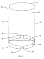
Figure 1 provides an illustration of a representative embodiment of the present invention, wherein a foldable air insulating sleeve comprises a rim, an inner base and an outer base, where the inner base and outer base are connected. -
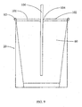
Figure 2 provides an illustration of a representative embodiment of the present invention that houses a cup. -
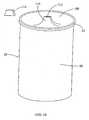
Figure 3 provides an illustration of a representative foldable air insulating sleeve in folded position. -
Figure 4 provides an illustration of another representative foldable air insulating sleeve with cup that is not part of the invention where the foldable air insulating sleeve includes an inner base but no outer base. -
Figure 5 shows an alternative illustration of the foldable air insulating sleeve ofFig. 4 in folded position without outer base. -
Figure 6 provides an illustration of another representative foldable air insulating sleeve with cup that is not part of the invention that includes a modified inner base. -
Figure 7 provides an illustration of the foldable air insulating sleeve with modified inner base ofFig. 6 in folded position. -
Figure 8 provides an illustration of the foldable air insulating sleeve with a hollow food container lid. -
Figure 9 provides an illustration of the foldable air insulating sleeve with a hollow cold drink lid. -
Figure 10 provides an illustration of the foldable air insulating sleeve with a hollow hot drink lid and cap. -
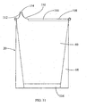
Figure 11 provides a cross-sectional illustration of the foldable air insulating sleeve with a hollow hot drink lid and cap. -
Figure 12 provides a cross-sectional illustration of a cup with a hollow food container lid where the air chamber is placed above the lid. -
Figure 13 provides a cross-sectional illustration of a cup with a hollow cold drink lid where the air chamber is placed above the lid. -
Figure 14 provides a cross-sectional illustration of a cup with a hemispherical hollow cold drink lid. -
Figure 15 provides a cross-sectional illustration of a cup with a hollow hot drink lid and cap where the air chamber is placed above the lid. -
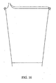
Figure 16 provides a cross-sectional illustration of a cup with an alternate hollow hot drink lid and cap where the air chamber is placed above the lid. - The present invention relates to insulating devices for beverage containers, and more particularly, to insulating beverages and foods by using air as the insulator.
- In the disclosure and in the claims the term "cup" shall refer to any container used to house consumable liquids and solids. Examples of cups include disposable cups, small soup bowls and any other similarly shaped container from which one drinks or eats that is in need of insulation.
-
Figure 1 illustrates a transparent view of a foldableair insulating sleeve 20 that includes a substantially tubularouter shell 30, arim 32, aninner base 34, anouter base 36, a firstbase connection strip 38 and a secondbase connection strip 40. The substantially tubularouter shell 30 has a firstlongitudinal fold 42 and a secondlongitudinal fold 44. The firstbase connection strip 38 has a first baseconnection strip fold 46 and the secondbase connection strip 40 has a second baseconnection strip fold 48. Finally, theinner base 34 has aninner base fold 50. -
Figure 2 illustrates a transparent view of foldableair insulating sleeve 20 with acup 60, where thecup 60 has atop rim 62, abottom edge 64 and a supportingwall 66. In the illustrated embodiment, therim 32 of the foldableair insulating sleeve 20 connects to thetop rim 62 of thecup 60. Thebottom edge 64 of thecup 60 is supported by theinner base 34 of the foldableair insulating sleeve 20. Once thecup 60 is connected to the foldableair insulating sleeve 20, a first pocket ofair 68 is created, which together with a second pocket ofair 70, insulates the contents of thecup 60. Once connected, a user can carry thecup 60 by grasping the substantially tubularouter shell 30. -
Figure 3 illustrates a transparent view of a foldable air insulating sleeve in foldedposition 80. In this embodiment,inner base 34 is folded alonginner base fold 50, firstbase connection strip 38 is folded along first baseconnection strip fold 46, secondbase connection strip 40 is folded along second baseconnection strip fold 48 and substantially tubularouter shell 30 is folded along firstlongitudinal fold 42 and secondlongitudinal fold 44 so that foldable air insulating sleeve in foldedposition 80 is in a substantially flat condition. When folded, theinner base fold 50 is parallel to therim 32 and when open, theinner base fold 50 is perpendicular to therim 32. - With reference now to
Figure 4 , another embodiment that is not part of the present invention is illustrated as foldableair insulating sleeve 20 withcup 60, where foldableair insulating sleeve 20 includesinner base 34 but does not includeouter base 36. In this embodiment,inner base 34 supports bothcup 60 and foldableair insulating sleeve 20.Inner base 34 also folds alonginner base fold 50, first baseconnection strip fold 46 and second baseconnection strip fold 48. -
Figure 5 shows an alternative illustration of the foldable air insulating sleeve ofFig. 4 in foldedposition 80 withoutouter base 36. In this embodiment,inner base 34 is folded alonginner base fold 50, firstbase connection strip 38 is folded along a first base connectionstrip fold line 52, secondbase connection strip 40 is folded along a second base connectionstrip fold line 54 and substantially tubularouter shell 30 is folded along firstlongitudinal fold 42 and secondlongitudinal fold 44 so that foldable air insulating sleeve in foldedposition 80 is in a substantially flat condition. When folded,inner base fold 50 is parallel to therim 32 and when open,inner base fold 50 is perpendicular torim 32. - With reference now to
Figure 6 , another embodiment that is not part of the present invention is illustrated as foldableair insulating sleeve 20 withcup 60, where foldableair insulating sleeve 20 includes modifiedinner base 90. Modifiedinner base 90 comprises abase portion 92 and anopening 94. In this embodiment,cup 60 protrudes throughopening 94 until supportingwall 66 ofcup 60 prohibits further travel or untilbottom edge 64 ofcup 60 reachesouter base 36. -
Figure 7 shows the foldableair insulating sleeve 20 with modifiedinner base 90 ofFig. 6 in folded position. Modifiedinner base 90 folds along first modifiedinner base fold 96, second modifiedinner base fold 98, first baseconnection strip fold 46 and second baseconnection strip fold 48. When folded, first modifiedinner base fold 96 and second modifiedinner base fold 98 are parallel torim 32 and when open, first modifiedinner base fold 96 and second modifiedinner base fold 98 are perpendicular torim 32. -
Figure 8 shows foldableair insulating sleeve 20 with a hollowfood container lid 100 that attaches totop rim 62 ofcup 60 and includes anair insulating chamber 101. -
Figure 9 illustrates foldableair insulating sleeve 20 with a hollowcold drink lid 102 that attaches totop rim 62 ofcup 60 and has astraw opening 104 through which astraw 106 is placed. Hollowcold drink lid 102 also includesair insulating chamber 101 that insulates contents ofcup 60. -
Figure 10 illustrates foldableair insulating sleeve 20 with a hollowhot drink lid 108, arounded mouth piece 110, a hollow hotdrink lid opening 112 and acap 114. Hollowhot drink lid 108 attaches totop rim 62 ofcup 60.Cap 114 covers hollow hotdrink lid opening 112, insulating the contents ofcup 60. -
Figure 11 illustrates a transparent view of foldableair insulating sleeve 20 with hollowhot drink lid 108 where first pocket ofair 68, insulatingair chamber 101 and a third pocket ofair 116 insulate the contents ofcup 60. In this illustration,cap 114 is coupled torounded mouth piece 110, covering hollow hotdrink lid opening 112 and further insulating the contents ofcup 60. -
Figure 12 illustrates a cup with a hollow food container lid that attaches to top rim of cup and includes an insulating air chamber placed above the lid. -
Figure 13 shows a cup with a hollow cold drink lid that attaches to top rim of cup and has a straw opening through which a straw is placed where the insulating air chamber is placed above the lid. -
Figure 14 illustrates a cup with a hemispherical hollow cold drink lid that attaches to top rim of cup and has a straw opening through which a straw is placed and an insulating air chamber. -
Figure 15 illustrates a cup with a hollow hot drink lid, a rounded mouth piece, and a cap. Hollow hot drink lid attaches to top rim of cup and cap covers hollow hot drink lid opening. The insulating air chamber is placed above the lid. -
Figure 16 shows a cup with an alternate hollow hot drink lid, rounded mouth piece, and a cap. Hot drink lid attaches to top rim of cup and cap covers hollow hot drink lid opening. The insulating air chamber is placed above the lid. - Thus, as discussed herein, the embodiments of the present invention embrace the field insulating devices for beverage containers. In particular, the present invention relates to insulating disposable cups by using air as the insulator. The present invention may be embodied in other specific forms without departing from its essential characteristics. The described embodiments are to be considered in all respects only as illustrative and not restrictive. The scope of the invention is, therefore, indicated by the appended claims rather than by the foregoing description.
Claims (15)
- An air insulating system, the air insulating system comprising:a cup (60); anda foldable air insulating sleeve (20) configured to insulate said cup (60) via at least a continuous circumferential first pocket of air (68), said pocket of air (68) being substantially completely enclosed by said cup (60) and said air insulating sleeve (20), and said foldable air insulating sleeve (20) comprising:a substantially tubular outer shell (30);a rim (32);an inner base (34); and the system being characterised in that thesleeve (20) comprises an outer base (36), wherein said inner base (34) and said outer base (36) are connected by at least one base connection strip (38) and are separated by an air space when the foldable air insulating sleeve (20) is in a unfolded insulating position;and in that said substantially tubular outer shell (30) is foldable along at least two longitudinal folds (42, 44) and wherein said inner base (34) and said outer base (36) are foldable so that said inner base (34) and said outer base (36) are parallel to said rim (32) when folded and perpendicular to said rim (32) when open and wherein said substantially tubular outer shell (30) is foldable into a substantially flat condition.
- An air insulating system as recited in claim 1, wherein said rim (32) of said foldable air insulating sleeve (20) is coupled to a top rim (62) of said cup (60) and said inner base (34) of said foldable insulating sleeve (20) supports a bottom edge (64) of said cup (60).
- An air insulating system as recited in claim 1, wherein said foldable air insulating sleeve's inner base (34) has an opening through which said cup (60) enters until said cup (60) is either too wide and is stopped from further passage or until said cup (60) meets said outer base (36) of said foldable air insulating sleeve (20).
- An air insulating system as recited in claim 1, wherein said bottom edge (64) of said cup (60) is narrower than said top rim (62), causing, when coupled to said foldable air insulating sleeve (20), the area of said first pocket of air (68) to be greater near said bottom edge (64) of said cup (60) than at said top rim (62).
- An air insulating system as recited in claim 1, wherein said first pocket of air (68) exists between said substantially tubular outer shell (30) of said foldable air insulating sleeve (20) and said cup (60).
- An air insulating system as recited in claim 1, wherein a second pocket of air (70) exists between said inner base (34) and said outer base (36) of said foldable air insulating sleeve (20).
- An air insulating system as recited in claim 1, wherein said foldable air insulating sleeve (20) is made substantially out of at least one of the following materials:i) plastic; andii) paper.
- An air insulating system as recited in claim 1, wherein the inner base (34) has an inner base fold (50).
- A method for insulating cup (60), the method comprising:providing a foldable air insulating sleeve (20), the foldable air insulating sleeve (20) configured to insulate said cup (60) via at least a continuous circumferential first pocket of air (68), said pocket of air (68) being substantially completely enclosed by said cup (20) and said air insulating sleeve (20), and said foldable air insulating sleeve (20) comprising:a substantially tubular outer shell (30);a rim (32);an inner base (34); andan outer base (36), wherein said inner base (34) and said outer base (36) are connected by at least one base connection strip (38) and are separated by an air space when the foldable air insulating sleeve (20) is in a unfolded insulating position;wherein said substantially tubular outer shell (30) is foldable along at least two longitudinal folds (42, 44) and wherein said inner base (34) and said outer base (36) are foldable so that said inner base (34) and said outer base (36) are parallel to said rim (32) when folded and perpendicular to said rim (32) when open and wherein said substantially tubular outer shell (30) is foldable into a substantially flat condition;coupling said foldable air insulating sleeve (20) to said cup (60) to form at least said first pocket of air (68); andinsulating said cup (60) using at least said first pocket of air (68).
- A method as recited in claim 9, wherein said rim (32) of said foldable air insulating sleeve (20) is coupled to a top rim (62) of said cup (60) and said inner base (34) of said foldable insulating sleeve (20) supports a bottom edge (64) of said cup (60).
- A method as recited in claim 9, wherein said foldable air insulating sleeve's inner base (34) has an opening through which said cup (60) enters until said cup (60) is either too wide and is stopped from further passage or until said cup (60) meets said outer base (36) of said foldable air insulating sleeve (20).
- A method as recited in claim 9, wherein said bottom edge (64) of said cup (60) is narrower than said top rim (62), causing, when coupled to said foldable air insulating sleeve (20), the area of said first pocket of air (68) to be greater near said bottom edge (64) of said cup (60) than at said top rim (62).
- A method as recited in claim 9, wherein said first pocket of air (68) exists between said substantially tubular outer shell (30) of said foldable air insulating sleeve (20) and said cup (60).
- A method as recited in claim 9, wherein a second pocket of air (70) exists between said inner base (34) and said outer base (36) of said foldable air insulating sleeve (20).
- A method as recited in claim 9, wherein said foldable air insulating sleeve (20) is made substantially out of at least one of the following materials:i) plastic; andii) paper.
Applications Claiming Priority (3)
| Application Number | Priority Date | Filing Date | Title |
|---|---|---|---|
| US10/459,337 US7290679B2 (en) | 2003-06-11 | 2003-06-11 | Foldable air insulating sleeve |
| US50168303P | 2003-09-10 | 2003-09-10 | |
| PCT/US2004/017209 WO2005000038A2 (en) | 2003-06-11 | 2004-05-28 | Foldable air insulating sleeve |
Publications (3)
| Publication Number | Publication Date |
|---|---|
| EP1633643A2 EP1633643A2 (en) | 2006-03-15 |
| EP1633643A4 EP1633643A4 (en) | 2008-04-23 |
| EP1633643B1 true EP1633643B1 (en) | 2009-12-16 |
Family
ID=33555094
Family Applications (1)
| Application Number | Title | Priority Date | Filing Date |
|---|---|---|---|
| EP04753930A Active EP1633643B1 (en) | 2003-06-11 | 2004-05-28 | Foldable air insulating sleeve |
Country Status (12)
| Country | Link |
|---|---|
| EP (1) | EP1633643B1 (en) |
| JP (1) | JP4578479B2 (en) |
| KR (1) | KR101314024B1 (en) |
| AT (1) | ATE452074T1 (en) |
| AU (1) | AU2004251648B2 (en) |
| BR (1) | BRPI0411320B1 (en) |
| CA (1) | CA2529000C (en) |
| DE (1) | DE602004024677D1 (en) |
| ES (1) | ES2338328T3 (en) |
| MX (1) | MXPA05013561A (en) |
| RU (1) | RU2369546C2 (en) |
| WO (1) | WO2005000038A2 (en) |
Families Citing this family (4)
| Publication number | Priority date | Publication date | Assignee | Title |
|---|---|---|---|---|
| US7537136B2 (en) * | 2003-06-11 | 2009-05-26 | Laurent Hechmati | Foldable air insulating sleeve |
| KR102289413B1 (en) * | 2018-09-07 | 2021-08-17 | 우봉윤 | Paper cup of dual structure and manufacturing method thereof |
| WO2020050681A1 (en) * | 2018-09-07 | 2020-03-12 | 우봉윤 | Paper cup of dual structure and method for manufacturing same |
| RU198547U1 (en) * | 2019-11-11 | 2020-07-15 | Общество с ограниченной ответственностью "Сушильные технологии" | Thermal insulation packaging for instant food concentrates |
Family Cites Families (15)
| Publication number | Priority date | Publication date | Assignee | Title |
|---|---|---|---|---|
| US3337109A (en) * | 1965-02-26 | 1967-08-22 | Sweetheart Plastics | Container holders |
| JPS5979085U (en) * | 1982-11-20 | 1984-05-29 | 菅原 甲巳 | Kotop cover |
| JPS59189589U (en) * | 1983-06-03 | 1984-12-15 | 佐々木 則義 | glass cover |
| JPS6123879U (en) * | 1984-07-20 | 1986-02-12 | 東洋ガラス株式会社 | coaster |
| JPH0329910U (en) * | 1989-07-31 | 1991-03-25 | ||
| JPH0386970U (en) * | 1989-12-26 | 1991-09-03 | ||
| US5180079A (en) * | 1992-04-06 | 1993-01-19 | John Jeng | Combined cup |
| US5320249A (en) * | 1993-06-17 | 1994-06-14 | Strech Kenneth R | Insulated jacket for a conical container |
| JPH077574U (en) * | 1993-07-15 | 1995-02-03 | 義憲 西村 | Straws that won't come out |
| US5363982A (en) * | 1994-03-07 | 1994-11-15 | Sadlier Claus E | Multi-layered insulated cup formed of one continuous sheet |
| JP3108617B2 (en) * | 1995-11-22 | 2000-11-13 | 日本酸素株式会社 | Tableware and tableware lids |
| US6059140A (en) * | 1998-03-31 | 2000-05-09 | Numo Manufacturing Acquistion Corporation | Insulated jacket for a beverage container and blank and method for fabricating same |
| JP4446523B2 (en) * | 1999-10-25 | 2010-04-07 | 東罐興業株式会社 | muddler |
| US6412686B1 (en) * | 2000-01-05 | 2002-07-02 | Designmahl Ltd. | Thermal insulating sleeve for a container |
| US7537136B2 (en) * | 2003-06-11 | 2009-05-26 | Laurent Hechmati | Foldable air insulating sleeve |
-
2004
- 2004-05-28 KR KR1020057023735A patent/KR101314024B1/en not_active IP Right Cessation
- 2004-05-28 MX MXPA05013561A patent/MXPA05013561A/en active IP Right Grant
- 2004-05-28 AU AU2004251648A patent/AU2004251648B2/en not_active Ceased
- 2004-05-28 DE DE602004024677T patent/DE602004024677D1/en active Active
- 2004-05-28 EP EP04753930A patent/EP1633643B1/en active Active
- 2004-05-28 CA CA2529000A patent/CA2529000C/en active Active
- 2004-05-28 AT AT04753930T patent/ATE452074T1/en not_active IP Right Cessation
- 2004-05-28 WO PCT/US2004/017209 patent/WO2005000038A2/en active Application Filing
- 2004-05-28 BR BRPI0411320-9A patent/BRPI0411320B1/en not_active IP Right Cessation
- 2004-05-28 ES ES04753930T patent/ES2338328T3/en active Active
- 2004-05-28 JP JP2006533535A patent/JP4578479B2/en not_active Expired - Fee Related
- 2004-05-28 RU RU2006100300/12A patent/RU2369546C2/en not_active IP Right Cessation
Also Published As
| Publication number | Publication date |
|---|---|
| ES2338328T3 (en) | 2010-05-06 |
| ATE452074T1 (en) | 2010-01-15 |
| RU2006100300A (en) | 2006-08-10 |
| CA2529000C (en) | 2013-12-24 |
| BRPI0411320A (en) | 2006-07-18 |
| DE602004024677D1 (en) | 2010-01-28 |
| WO2005000038A2 (en) | 2005-01-06 |
| EP1633643A2 (en) | 2006-03-15 |
| AU2004251648A1 (en) | 2005-01-06 |
| WO2005000038B1 (en) | 2007-02-22 |
| WO2005000038A3 (en) | 2005-06-16 |
| CA2529000A1 (en) | 2005-01-06 |
| MXPA05013561A (en) | 2006-05-19 |
| KR20060035619A (en) | 2006-04-26 |
| BRPI0411320B1 (en) | 2018-02-14 |
| JP4578479B2 (en) | 2010-11-10 |
| KR101314024B1 (en) | 2013-10-01 |
| EP1633643A4 (en) | 2008-04-23 |
| RU2369546C2 (en) | 2009-10-10 |
| JP2007516734A (en) | 2007-06-28 |
| AU2004251648B2 (en) | 2010-10-28 |
Similar Documents
| Publication | Publication Date | Title |
|---|---|---|
| US7762424B2 (en) | Foldable air insulating sleeve | |
| US7537136B2 (en) | Foldable air insulating sleeve | |
| US6343735B1 (en) | Insulating sleeve | |
| US20060283868A1 (en) | Beverage container accessory | |
| EP1633643B1 (en) | Foldable air insulating sleeve | |
| GB2235523A (en) | Thermally insulated containers | |
| US20080210744A1 (en) | Insert for a Carrier Bag | |
| AU2005203649A1 (en) | An insulating sleeve for a beverage container |
Legal Events
| Date | Code | Title | Description |
|---|---|---|---|
| PUAI | Public reference made under article 153(3) epc to a published international application that has entered the european phase |
Free format text: ORIGINAL CODE: 0009012 |
|
| 17P | Request for examination filed |
Effective date: 20051222 |
|
| AK | Designated contracting states |
Kind code of ref document: A2 Designated state(s): AT BE BG CH CY CZ DE DK EE ES FI FR GB GR HU IE IT LI LU MC NL PL PT RO SE SI SK TR |
|
| DAX | Request for extension of the european patent (deleted) | ||
| R17D | Deferred search report published (corrected) |
Effective date: 20070222 |
|
| A4 | Supplementary search report drawn up and despatched |
Effective date: 20080325 |
|
| 17Q | First examination report despatched |
Effective date: 20080711 |
|
| GRAP | Despatch of communication of intention to grant a patent |
Free format text: ORIGINAL CODE: EPIDOSNIGR1 |
|
| GRAS | Grant fee paid |
Free format text: ORIGINAL CODE: EPIDOSNIGR3 |
|
| GRAA | (expected) grant |
Free format text: ORIGINAL CODE: 0009210 |
|
| AK | Designated contracting states |
Kind code of ref document: B1 Designated state(s): AT BE BG CH CY CZ DE DK EE ES FI FR GB GR HU IE IT LI LU MC NL PL PT RO SE SI SK TR |
|
| REG | Reference to a national code |
Ref country code: GB Ref legal event code: FG4D |
|
| REG | Reference to a national code |
Ref country code: CH Ref legal event code: EP |
|
| REG | Reference to a national code |
Ref country code: IE Ref legal event code: FG4D |
|
| REF | Corresponds to: |
Ref document number: 602004024677 Country of ref document: DE Date of ref document: 20100128 Kind code of ref document: P |
|
| REG | Reference to a national code |
Ref country code: NL Ref legal event code: VDEP Effective date: 20091216 |
|
| PG25 | Lapsed in a contracting state [announced via postgrant information from national office to epo] |
Ref country code: SE Free format text: LAPSE BECAUSE OF FAILURE TO SUBMIT A TRANSLATION OF THE DESCRIPTION OR TO PAY THE FEE WITHIN THE PRESCRIBED TIME-LIMIT Effective date: 20091216 Ref country code: FI Free format text: LAPSE BECAUSE OF FAILURE TO SUBMIT A TRANSLATION OF THE DESCRIPTION OR TO PAY THE FEE WITHIN THE PRESCRIBED TIME-LIMIT Effective date: 20091216 |
|
| REG | Reference to a national code |
Ref country code: ES Ref legal event code: FG2A Ref document number: 2338328 Country of ref document: ES Kind code of ref document: T3 |
|
| PG25 | Lapsed in a contracting state [announced via postgrant information from national office to epo] |
Ref country code: PL Free format text: LAPSE BECAUSE OF FAILURE TO SUBMIT A TRANSLATION OF THE DESCRIPTION OR TO PAY THE FEE WITHIN THE PRESCRIBED TIME-LIMIT Effective date: 20091216 Ref country code: SI Free format text: LAPSE BECAUSE OF FAILURE TO SUBMIT A TRANSLATION OF THE DESCRIPTION OR TO PAY THE FEE WITHIN THE PRESCRIBED TIME-LIMIT Effective date: 20091216 |
|
| PG25 | Lapsed in a contracting state [announced via postgrant information from national office to epo] |
Ref country code: AT Free format text: LAPSE BECAUSE OF FAILURE TO SUBMIT A TRANSLATION OF THE DESCRIPTION OR TO PAY THE FEE WITHIN THE PRESCRIBED TIME-LIMIT Effective date: 20091216 |
|
| PG25 | Lapsed in a contracting state [announced via postgrant information from national office to epo] |
Ref country code: RO Free format text: LAPSE BECAUSE OF FAILURE TO SUBMIT A TRANSLATION OF THE DESCRIPTION OR TO PAY THE FEE WITHIN THE PRESCRIBED TIME-LIMIT Effective date: 20091216 Ref country code: PT Free format text: LAPSE BECAUSE OF FAILURE TO SUBMIT A TRANSLATION OF THE DESCRIPTION OR TO PAY THE FEE WITHIN THE PRESCRIBED TIME-LIMIT Effective date: 20100416 Ref country code: BG Free format text: LAPSE BECAUSE OF FAILURE TO SUBMIT A TRANSLATION OF THE DESCRIPTION OR TO PAY THE FEE WITHIN THE PRESCRIBED TIME-LIMIT Effective date: 20100316 Ref country code: EE Free format text: LAPSE BECAUSE OF FAILURE TO SUBMIT A TRANSLATION OF THE DESCRIPTION OR TO PAY THE FEE WITHIN THE PRESCRIBED TIME-LIMIT Effective date: 20091216 Ref country code: NL Free format text: LAPSE BECAUSE OF FAILURE TO SUBMIT A TRANSLATION OF THE DESCRIPTION OR TO PAY THE FEE WITHIN THE PRESCRIBED TIME-LIMIT Effective date: 20091216 |
|
| PG25 | Lapsed in a contracting state [announced via postgrant information from national office to epo] |
Ref country code: SK Free format text: LAPSE BECAUSE OF FAILURE TO SUBMIT A TRANSLATION OF THE DESCRIPTION OR TO PAY THE FEE WITHIN THE PRESCRIBED TIME-LIMIT Effective date: 20091216 Ref country code: CZ Free format text: LAPSE BECAUSE OF FAILURE TO SUBMIT A TRANSLATION OF THE DESCRIPTION OR TO PAY THE FEE WITHIN THE PRESCRIBED TIME-LIMIT Effective date: 20091216 Ref country code: BE Free format text: LAPSE BECAUSE OF FAILURE TO SUBMIT A TRANSLATION OF THE DESCRIPTION OR TO PAY THE FEE WITHIN THE PRESCRIBED TIME-LIMIT Effective date: 20091216 |
|
| PGFP | Annual fee paid to national office [announced via postgrant information from national office to epo] |
Ref country code: DE Payment date: 20100527 Year of fee payment: 7 |
|
| PLBE | No opposition filed within time limit |
Free format text: ORIGINAL CODE: 0009261 |
|
| STAA | Information on the status of an ep patent application or granted ep patent |
Free format text: STATUS: NO OPPOSITION FILED WITHIN TIME LIMIT |
|
| PG25 | Lapsed in a contracting state [announced via postgrant information from national office to epo] |
Ref country code: GR Free format text: LAPSE BECAUSE OF FAILURE TO SUBMIT A TRANSLATION OF THE DESCRIPTION OR TO PAY THE FEE WITHIN THE PRESCRIBED TIME-LIMIT Effective date: 20100317 Ref country code: CY Free format text: LAPSE BECAUSE OF FAILURE TO SUBMIT A TRANSLATION OF THE DESCRIPTION OR TO PAY THE FEE WITHIN THE PRESCRIBED TIME-LIMIT Effective date: 20091216 |
|
| 26N | No opposition filed |
Effective date: 20100917 |
|
| PG25 | Lapsed in a contracting state [announced via postgrant information from national office to epo] |
Ref country code: MC Free format text: LAPSE BECAUSE OF NON-PAYMENT OF DUE FEES Effective date: 20100531 |
|
| REG | Reference to a national code |
Ref country code: CH Ref legal event code: PL |
|
| PG25 | Lapsed in a contracting state [announced via postgrant information from national office to epo] |
Ref country code: DK Free format text: LAPSE BECAUSE OF FAILURE TO SUBMIT A TRANSLATION OF THE DESCRIPTION OR TO PAY THE FEE WITHIN THE PRESCRIBED TIME-LIMIT Effective date: 20091216 |
|
| PG25 | Lapsed in a contracting state [announced via postgrant information from national office to epo] |
Ref country code: CH Free format text: LAPSE BECAUSE OF NON-PAYMENT OF DUE FEES Effective date: 20100531 Ref country code: LI Free format text: LAPSE BECAUSE OF NON-PAYMENT OF DUE FEES Effective date: 20100531 |
|
| PG25 | Lapsed in a contracting state [announced via postgrant information from national office to epo] |
Ref country code: IE Free format text: LAPSE BECAUSE OF NON-PAYMENT OF DUE FEES Effective date: 20100528 |
|
| PGFP | Annual fee paid to national office [announced via postgrant information from national office to epo] |
Ref country code: ES Payment date: 20111123 Year of fee payment: 8 Ref country code: FR Payment date: 20111205 Year of fee payment: 8 |
|
| PG25 | Lapsed in a contracting state [announced via postgrant information from national office to epo] |
Ref country code: IT Free format text: LAPSE BECAUSE OF NON-PAYMENT OF DUE FEES Effective date: 20110528 |
|
| PG25 | Lapsed in a contracting state [announced via postgrant information from national office to epo] |
Ref country code: LU Free format text: LAPSE BECAUSE OF NON-PAYMENT OF DUE FEES Effective date: 20100528 Ref country code: HU Free format text: LAPSE BECAUSE OF FAILURE TO SUBMIT A TRANSLATION OF THE DESCRIPTION OR TO PAY THE FEE WITHIN THE PRESCRIBED TIME-LIMIT Effective date: 20100617 |
|
| PGFP | Annual fee paid to national office [announced via postgrant information from national office to epo] |
Ref country code: IT Payment date: 20111124 Year of fee payment: 8 |
|
| PG25 | Lapsed in a contracting state [announced via postgrant information from national office to epo] |
Ref country code: TR Free format text: LAPSE BECAUSE OF FAILURE TO SUBMIT A TRANSLATION OF THE DESCRIPTION OR TO PAY THE FEE WITHIN THE PRESCRIBED TIME-LIMIT Effective date: 20091216 |
|
| PGRI | Patent reinstated in contracting state [announced from national office to epo] |
Ref country code: IT Effective date: 20120630 |
|
| GBPC | Gb: european patent ceased through non-payment of renewal fee |
Effective date: 20120528 |
|
| PGRI | Patent reinstated in contracting state [announced from national office to epo] |
Ref country code: IT Effective date: 20120630 |
|
| REG | Reference to a national code |
Ref country code: FR Ref legal event code: ST Effective date: 20130131 |
|
| REG | Reference to a national code |
Ref country code: DE Ref legal event code: R119 Ref document number: 602004024677 Country of ref document: DE Effective date: 20121201 |
|
| PG25 | Lapsed in a contracting state [announced via postgrant information from national office to epo] |
Ref country code: FR Free format text: LAPSE BECAUSE OF NON-PAYMENT OF DUE FEES Effective date: 20120531 |
|
| PG25 | Lapsed in a contracting state [announced via postgrant information from national office to epo] |
Ref country code: DE Free format text: LAPSE BECAUSE OF NON-PAYMENT OF DUE FEES Effective date: 20121201 |
|
| REG | Reference to a national code |
Ref country code: ES Ref legal event code: FD2A Effective date: 20130820 |
|
| PG25 | Lapsed in a contracting state [announced via postgrant information from national office to epo] |
Ref country code: ES Free format text: LAPSE BECAUSE OF NON-PAYMENT OF DUE FEES Effective date: 20120529 |
|
| REG | Reference to a national code |
Ref country code: GB Ref legal event code: S28 Free format text: APPLICATION FILED |
|
| REG | Reference to a national code |
Ref country code: GB Ref legal event code: S28 Free format text: RESTORATION ALLOWED Effective date: 20140423 |
|
| PG25 | Lapsed in a contracting state [announced via postgrant information from national office to epo] |
Ref country code: GB Free format text: THE PATENT HAS BEEN ANNULLED BY A DECISION OF A NATIONAL AUTHORITY Effective date: 20120528 |
|
| PGFP | Annual fee paid to national office [announced via postgrant information from national office to epo] |
Ref country code: GB Payment date: 20170519 Year of fee payment: 14 |
|
| GBPC | Gb: european patent ceased through non-payment of renewal fee |
Effective date: 20180528 |
|
| PG25 | Lapsed in a contracting state [announced via postgrant information from national office to epo] |
Ref country code: GB Free format text: THE PATENT HAS BEEN ANNULLED BY A DECISION OF A NATIONAL AUTHORITY Effective date: 20180528 |