US6412686B1 - Thermal insulating sleeve for a container - Google Patents
Thermal insulating sleeve for a container Download PDFInfo
- Publication number
- US6412686B1 US6412686B1 US09/477,864 US47786400A US6412686B1 US 6412686 B1 US6412686 B1 US 6412686B1 US 47786400 A US47786400 A US 47786400A US 6412686 B1 US6412686 B1 US 6412686B1
- Authority
- US
- United States
- Prior art keywords
- sleeve
- thermal insulating
- insulating sleeve
- container
- tubular body
- Prior art date
- Legal status (The legal status is an assumption and is not a legal conclusion. Google has not performed a legal analysis and makes no representation as to the accuracy of the status listed.)
- Expired - Lifetime
Links
Images


Classifications
-
- B—PERFORMING OPERATIONS; TRANSPORTING
- B65—CONVEYING; PACKING; STORING; HANDLING THIN OR FILAMENTARY MATERIAL
- B65D—CONTAINERS FOR STORAGE OR TRANSPORT OF ARTICLES OR MATERIALS, e.g. BAGS, BARRELS, BOTTLES, BOXES, CANS, CARTONS, CRATES, DRUMS, JARS, TANKS, HOPPERS, FORWARDING CONTAINERS; ACCESSORIES, CLOSURES, OR FITTINGS THEREFOR; PACKAGING ELEMENTS; PACKAGES
- B65D81/00—Containers, packaging elements, or packages, for contents presenting particular transport or storage problems, or adapted to be used for non-packaging purposes after removal of contents
- B65D81/38—Containers, packaging elements, or packages, for contents presenting particular transport or storage problems, or adapted to be used for non-packaging purposes after removal of contents with thermal insulation
- B65D81/3876—Containers, packaging elements, or packages, for contents presenting particular transport or storage problems, or adapted to be used for non-packaging purposes after removal of contents with thermal insulation insulating sleeves or jackets for cans, bottles, barrels, etc.
- B65D81/3881—Containers, packaging elements, or packages, for contents presenting particular transport or storage problems, or adapted to be used for non-packaging purposes after removal of contents with thermal insulation insulating sleeves or jackets for cans, bottles, barrels, etc. formed with double walls, i.e. hollow
-
- B—PERFORMING OPERATIONS; TRANSPORTING
- B65—CONVEYING; PACKING; STORING; HANDLING THIN OR FILAMENTARY MATERIAL
- B65D—CONTAINERS FOR STORAGE OR TRANSPORT OF ARTICLES OR MATERIALS, e.g. BAGS, BARRELS, BOTTLES, BOXES, CANS, CARTONS, CRATES, DRUMS, JARS, TANKS, HOPPERS, FORWARDING CONTAINERS; ACCESSORIES, CLOSURES, OR FITTINGS THEREFOR; PACKAGING ELEMENTS; PACKAGES
- B65D5/00—Rigid or semi-rigid containers of polygonal cross-section, e.g. boxes, cartons or trays, formed by folding or erecting one or more blanks made of paper
- B65D5/02—Rigid or semi-rigid containers of polygonal cross-section, e.g. boxes, cartons or trays, formed by folding or erecting one or more blanks made of paper by folding or erecting a single blank to form a tubular body with or without subsequent folding operations, or the addition of separate elements, to close the ends of the body
- B65D5/0281—Rigid or semi-rigid containers of polygonal cross-section, e.g. boxes, cartons or trays, formed by folding or erecting one or more blanks made of paper by folding or erecting a single blank to form a tubular body with or without subsequent folding operations, or the addition of separate elements, to close the ends of the body the tubular body presenting double or multiple walls
-
- B—PERFORMING OPERATIONS; TRANSPORTING
- B65—CONVEYING; PACKING; STORING; HANDLING THIN OR FILAMENTARY MATERIAL
- B65D—CONTAINERS FOR STORAGE OR TRANSPORT OF ARTICLES OR MATERIALS, e.g. BAGS, BARRELS, BOTTLES, BOXES, CANS, CARTONS, CRATES, DRUMS, JARS, TANKS, HOPPERS, FORWARDING CONTAINERS; ACCESSORIES, CLOSURES, OR FITTINGS THEREFOR; PACKAGING ELEMENTS; PACKAGES
- B65D5/00—Rigid or semi-rigid containers of polygonal cross-section, e.g. boxes, cartons or trays, formed by folding or erecting one or more blanks made of paper
- B65D5/02—Rigid or semi-rigid containers of polygonal cross-section, e.g. boxes, cartons or trays, formed by folding or erecting one or more blanks made of paper by folding or erecting a single blank to form a tubular body with or without subsequent folding operations, or the addition of separate elements, to close the ends of the body
- B65D5/029—Rigid or semi-rigid containers of polygonal cross-section, e.g. boxes, cartons or trays, formed by folding or erecting one or more blanks made of paper by folding or erecting a single blank to form a tubular body with or without subsequent folding operations, or the addition of separate elements, to close the ends of the body the tubular body presenting a special shape
-
- Y—GENERAL TAGGING OF NEW TECHNOLOGICAL DEVELOPMENTS; GENERAL TAGGING OF CROSS-SECTIONAL TECHNOLOGIES SPANNING OVER SEVERAL SECTIONS OF THE IPC; TECHNICAL SUBJECTS COVERED BY FORMER USPC CROSS-REFERENCE ART COLLECTIONS [XRACs] AND DIGESTS
- Y10—TECHNICAL SUBJECTS COVERED BY FORMER USPC
- Y10S—TECHNICAL SUBJECTS COVERED BY FORMER USPC CROSS-REFERENCE ART COLLECTIONS [XRACs] AND DIGESTS
- Y10S229/00—Envelopes, wrappers, and paperboard boxes
- Y10S229/939—Container made of corrugated paper or corrugated paperboard
Definitions
- the present invention is directed to a thermal insulating sleeve and more specifically, to a new and novel thermal insulating sleeve for insulating a container, such as a beverage container, that is easily converted from a relatively flat or planar configuration during periods of nonuse and into an open configuration for receiving a container during periods of use.
- Thermal insulating sleeves such as those used for insulating beverage containers, have been developed and are typically formed from polystyrene, expanded synthetic resins, or paper or cardboard material. While sleeves formed of polystyrene and expanded synthetic resins are aesthetically pleasing and provide good thermal insulation, they are not biodegradable or easily recyclable. Further, while such sleeves can generally be stacked or nested in an array, the resulting stack is generally bulky and often difficult to handle. Further, such sleeves cannot be stored or carried in a substantially planar configuration making them inconvenient for an individual to carry in a pocket, purse, and the like during periods of nonuse.
- Thermal insulating sleeves formed from corrugated box board material have also been developed. Unfortunately, however, until now, such insulated sleeves are typically bulky and do not easily fold or collapse into a generally planar configuration for periods of nonuse. Further, it is often desirable for sleeves used for thermally insulating containers, such as beverage containers, to have an outer surface onto which advertising material can be printed. However, until now, the corrugated fluting associated with sleeves formed from corrugated box board material has resulted in printed material having a generally poor appearance.
- Thermal insulating sleeves formed from polystyrene, expanded synthetic resins, or paper have also been designed to accommodate containers.
- containers such as used for beverages, vary slightly in size and sleeves that are properly sized to accommodate a particular size of beverage container are often not properly sized for accommodating a larger or a smaller size beverage container.
- a need exist for a new and novel thermally insulating sleeve for a container such as a beverage container, that can easily collapse into a substantially planar configuration during periods of nonuse and can be easily expanded into an open configuration for accommodating a container during periods of nonuse; is capable of accommodating containers of various sizes; is sturdy enough to withstand extensive handling; can be formed from a biodegradable and/or recyclable material; can be printed or embossed with printed images; is relatively inexpensive to manufacture; and is capable of being manufactured by existing machinery.
- the present invention is directed to a thermal insulating sleeve for a container, such as a beverage container.
- the insulating sleeve comprises a plurality of side panels defining a generally tubular body positioned about an imaginary longitudinal axis.
- the tubular body includes an open first end and a second end forming a central cavity therein.
- Circumferential positioned about the open first end and equally spaced one from another, is a plurality of fingers that extend generally radially inwardly into the central cavity and are angled generally downwardly with respect to the tubular body.
- the thermal insulating sleeve is formed from a unitary blank that is appropriately folded to form the insulating sleeve.
- the blank includes a plurality of adjacent, generally rectangular, side portions connected together each having a top end, a bottom end, and a finger extending outwardly from the top end.
- the blank further includes an end panel and a flap. When the blank is formed into the thermal insulating sleeve, the end panel and the flap are secured together in an overlapping relationship to form a tubular body.
- the thermal insulating sleeve comprises a bottom.
- the thermal insulating sleeve is formed from a unitary blank having first and second bottom closure flaps integral with and connected to the bottom ends of corresponding side portions and are connected together to form a bottom.
- the bottom of the thermal insulating sleeve is formed without the use of an adhesive.
- the bottom of the thermal insulating sleeve is formed with the use of an adhesive.
- the thermal insulating sleeve may be expanded into an open configuration for receiving a container and may be collapsed into a closed or generally planar configuration for shipping, storage, carrying, or the like.
- the tubular body of the thermal insulating sleeve includes an exterior wall for receiving printed material.
- the tubular body of the thermal insulating sleeve includes an exterior wall having a printed laminate mounted thereon.
- the thermal insulating sleeve is formed from a material capable of being die cut and folded.
- the thermal insulating sleeve is formed of paperboard having an appropriate crush resistance.
- the thermal insulating sleeve is formed of a f or an E/F paperboard material.
- the thermal insulating sleeve is formed of a plastic material.
- the thermal insulating sleeve is formed of a transparent plastic material.
- the thermal insulating sleeve provides an insulating layer of air between the interior wall of the tubular body forming the thermal insulating sleeve and the container contained therein.
- the thermal insulating sleeve is formed from a foldable material selected from the group consisting of paper, paperboard, cardboard, box board, plastic, and foam.
- a primary object of the present invention is to provide a thermal insulating sleeve for a container that is easily converted from a collapsed or planar configuration during periods of nonuse and into an expanded or open configuration for receiving a container during periods of use.
- Another primary object of the present invention is to provide a thermal insulating sleeve for a beverage container.
- Another primary object of the present invention is to provide a thermal insulating sleeve for a container that reduces or eliminates condensation from forming along the outside of a relatively cold container contained therein.
- Another primary object of the present invention is to provide a thermal insulating sleeve for a container which permits the container to be easily inserted into or out of the thermal insulating sleeve.
- Another primary object of the present invention is to provide a thermal insulating sleeve that may easily accommodate various sizes of containers.
- Another primary object of the present invention is to provide a thermal insulating sleeve for a container having a surface for displaying printed material.
- Another primary object of the present invention is to provide a thermal insulating sleeve for a container that is capable of withstanding prolonged handling.
- Another primary object of the present invention is to provide a thermal insulating sleeve for a container that is formed from biodegradable material.
- Another primary object of the present invention is to provide a thermal insulating sleeve for a container that is formed from recyclable material.
- Another primary object of the present invention is to provide a thermal insulating sleeve for a container that is relatively inexpensive to manufacture.
- Another primary object of the present invention is to provide a thermal insulating sleeve for a container that can be manufactured using existing machinery.
- FIG. 1 is a perspective view of the fully assembled thermal insulating sleeve for a container in its expanded or open container receiving configuration
- FIG. 2 is a plan view of a preferred embodiment of a blank which can be formed into the thermal insulating sleeve for a container of the present invention having a bottom formed without the use of an adhesive;
- FIG. 3 is a fragmentary sectional view of the thermal insulating sleeve of FIG. 1 taken at 3 — 3 thereof having a laminate, such as a lithography printed paper, mounted thereon;
- FIG. 4 is a plan view of another preferred embodiment of a blank which can be formed into the thermal insulating sleeve for a container of the present invention having a bottom formed with the use of an adhesive;
- FIG. 5 is a bottom plan view showing the bottom of the thermal insulating sleeve formed from the blank of FIG. 2;
- FIG. 6 is a bottom plan view showing the bottom of the thermal insulating sleeve formed from the blank of FIG. 4;
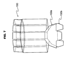
- FIG. 7 is a perspective view of the blank of FIG. 2 folded to form the partially assembled thermal insulating sleeve of FIG. 1 showing the fingers, the first closure flap, and the second closure flap in a non-folded condition;
- FIG. 8 is a perspective view of the blank of FIG. 2 folded to form the partially assembled thermal insulating sleeve of FIG. 1 showing the second closure flap folded inwardly;
- FIG. 9 is a perspective view of the blank of FIG. 2 folded to form the partially assembled thermal insulating sleeve of FIG. 1 showing the second closure flap and the first closure flap folded inwardly into an overlapping relationship to form a bottom;
- FIG. 10 is a perspective view of the blank of FIG. 2 folded to form the partially assembled thermal insulating sleeve of FIG. 1 showing some of the fingers folded inwardly into the central cavity and the first closure flap and the second closure flap folded in an overlapping relationship to form a bottom;
- FIG. 11 is a perspective view of the blank of FIG. 4 folded to form the partially assembled thermal insulating sleeve of FIG. 1 showing the fingers, the first closure flap, and the second closure flap in a non-folded condition;
- FIG. 12 is a perspective view of the blank of FIG. 4 folded to form the partially assembled thermal insulating sleeve of FIG. 1 showing the second closure flap folded inwardly;
- FIG. 13 is a perspective view of the blank of FIG. 4 folded to form the partially assembled thermal insulating sleeve of FIG. 1 showing the second closure flap and the first closure flap folded inwardly into an overlapping relationship to form a bottom;
- FIG. 14 is a perspective view of the blank of FIG. 4 folded to form the partially assembled thermal insulating sleeve of FIG. 1 showing some of the fingers folded inwardly into the central cavity and the first closure flap and the second closure flap folded in an overlapping relationship to form a bottom;
- FIG. 15 is a perspective view of the thermal insulating sleeve of FIG. 1 showing a container received therein;
- FIG. 16 is a longitudinal sectional view of the thermal insulating sleeve of FIG. 11 as taken at 16 — 16 thereof;
- FIG. 17 is a top view of the thermal insulating sleeve of FIG. 1 in its collapsed generally planar configuration.
- a preferred embodiment of a thermal insulating sleeve for a container is shown in its expanded or open configuration for receiving a container.
- the thermal insulating sleeve 100 comprises a plurality of side panels 102 defining a generally tubular body 104 , positioned about an imaginary longitudinal axis 106 , having an open first end 108 and a second end 110 forming a central cavity 114 therein.
- the insulating sleeve 100 further comprises a bottom 112 (FIGS. 5 and 6 ).
- the terms “inward” or “inwardly” correspond to the direction towards the imaginary longitudinal axis 106
- the terms “outward” or “outwardly” correspond to the direction away from the imaginary longitudinal axis 106 .
- the terms “upward” or “upwardly” correspond to the direction longitudinally towards the open first end 108 of the tubular body 104
- the terms “downward” or “downwardly” correspond to the direction longitudinally towards the second end 110 of the tubular body 104 .
- the sleeve 100 is preferably formed from a unitary blank 118 of paperboard of an appropriate crush resistance, preferably having a 150-pound burst rating of F or E/F paperboard material, such that an array of generally longitudinally extending fluted corrugating 119 (FIGS. 5 and 6) is positioned between the interior wall 120 and the exterior wall 122 of the tubular body 104 (FIG. 1 ).
- the use of a corrugated material provides strength as well as providing a plurality of thermally insulating air spaces between the interior wall 120 and the exterior wall 122 of the tubular body 104 .
- the blank 118 may be imprinted or embossed with advertising material, graphics, and the like, such that the material is displayed on the exterior wall 122 when the blank 118 is formed into the insulating sleeve 100 (FIG. 15 ).
- the blank 118 includes a laminate 124 (FIG.
- a lithography printed paper mounted thereon by an appropriate adhesive, such that when the blank 118 is formed into the thermal insulating sleeve 100 , the lithography printed paper is displayed outwardly showing the printed matter thereon.
- a F or E/F paperboard material permits lithography printed paper displaying photo-realistic images to have a relatively smooth and attractive appearance. It should now be apparent to those skilled in the art that forming the thermal insulating sleeve 100 from a transparent plastic will permit the container and any printed material contained thereon to be viewed while providing thermal insulation for the container.
- the blank 118 includes a plurality of adjacent, generally rectangular outer side portions 128 a and 128 b , inner side portions 128 c and center side portions 128 d connected together along longitudinally extending fold lines 132 , and each having a top end 134 and a bottom end 136 .
- Center side portions 128 d are connected together along a pair of generally parallel, longitudinally extending fold lines 138 .
- side portions 128 a , 128 b , 128 c and center side portions 128 d form the side panels 102 of the tubular body 104 for enclosing a container 140 (FIG. 15 ).
- the blank 118 includes ten side portions 128 a , 128 b , 128 c resulting in the thermal insulating sleeve 100 having a decahedron cross section (FIGS. 5 and 6 ). It has been found that a thermal insulating sleeve 100 for a container, such as a hand-held beverage container, having such a cross section is relatively comfortable to hold and permits the thermal insulating sleeve 100 to be easily collapsed into a planar configuration (FIG. 17) during periods of nonuse.
- thermal insulating sleeve 100 of the present invention may be easily formed having other geometric cross sections by simply increasing or decreasing the number of inner side portions 128 c comprising blank 118 . It should also now be apparent to those skilled in the art that when increasing or decreasing the number of inner side portions 128 c , an equal number of side portions 128 c should be maintained on each side of the center side portions 128 c to permit the thermal insulating sleeve 100 to collapse into a generally symmetric planar configuration (FIG. 17 ).
- the blank 118 further comprises an integral flap 142 attached to the outer edge 144 of the outer side portion 128 a along a pair of generally parallel, longitudinally extending fold lines 146 .
- the flap 142 is effective for overlapping and attaching to the opposite surface 148 of the outer side portion 128 b when the blank 118 is formed into the tubular body 104 .
- fingers 116 each include a lower portion 176 attached to the top end 134 of a corresponding side portion 128 a , 128 b and 128 c along transverse fold lines 178 , 180 , and an upper portion 182 integral with the lower portion 176 .
- Each finger 116 is separated from the lower portion 176 of an adjacent finger 116 by a slot 184 .
- the blank 118 is first folded along fold lines 132 and 138 to define the side panels 102 .
- An adhesive such as a glue, contact cement, or any other conventional means, is applied to a first surface 188 of flap 142 .
- the flap 142 is placed into overlapping relation with the opposite surface 148 of the outer side portion 128 b and are bonded together thereby forming the tubular body 102 .
- the blank further includes first and second bottom closure flaps, 150 a and 150 b , respectively, integral with and extending outwardly from bottom ends 136 of corresponding inner side portions 128 c along transverse fold lines 152 .
- the first bottom closure flap 150 a includes a generally rectangular body 154 having wings 156 and an outwardly longitudinally extending locking flap 158 .
- the second bottom closure flap 150 b also includes a generally rectangular body 160 having wings 162 which cooperate to form a cutout section 164 .
- the wings 156 and 162 are configured such that when the insulating sleeve 100 is assembled, as herein described, the first and second bottom closure flaps 150 a , 150 b cooperate to form the bottom 112 having the same cross section as the tubular body 104 (FIG. 5 ).
- the second bottom closure flap 150 a is first folded inwardly (FIG. 8 ). Then the first bottom closure flap 150 a is folded inwardly such that the locking flap 158 of the first bottom closure flap 150 a conventionally slips through the cut out section 164 of the second bottom closure flap 150 b (FIG. 9 ). The first closure flap 150 a and the second closure flap 150 b are then slidably locked together (FIG. 10) and may be urged downwardly, such as by the insertion of a container into the central cavity 114 of the thermal insulating sleeve 100 .
- the bottom 112 provides a bottom 112 formed without requiring the use of an adhesive. It should also now be apparent to those skilled in the art that by slidably locking the first closure flap 150 a and the second closure flap 150 b , permits the thermal insulating sleeve 100 to collapse into a generally planar configuration (FIG. 17 ). As shown in FIG. 10, fingers 116 are then folded inwardly along fold line 178 and downwardly into the central cavity 114 along fold line 180 thereby defining an upper edge 192 or lip of the insulating sleeve 100 .
- the first and second bottom closure flaps, 150 a and 150 b are formed such as each have peripheral edges 166 are substantially equal in length and have a substantially longer outer edge 168 .
- the first and second bottom closure flaps 150 a , 150 b cooperate to form the bottom 112 having the same cross section as the tubular body 104 .
- the first bottom closure flap 150 a further includes a outer segment 170 and an inner segment 172 defined by scored line 174 . As shown in FIGS.
- the bottom 112 is formed by folding the second bottom closure flap 150 b inwardly (FIG. 12) along fold line 152 and applying an adhesive to the downwardly facing surface 170 of the first bottom closure flap 150 a .
- the first bottom closure flap 150 a is folded inwardly along fold line 152 (FIG. 13) and along scored line 174 such that the upwardly facing surface 173 of outer segment 170 of the first bottom closure flap 150 a is placed into overlapping relation with the downwardly facing surface 175 of the second bottom closure flap 150 b and are bonded together to form bottom 112 (FIG. 14 ).
- bottom 112 formed using an adhesive provides a relatively stronger bottom than bottoms formed without the use of an adhesive or other such means. It should now be apparent to those skilled in the art that while the bottoms disclosed herein are the preferred embodiments, other forms of bottoms that permit the thermal insulating sleeve to expand into an open configuration and collaps into a generally planar configuration may also be used.
- a container 140 such as a beverage container
- fingers 116 operate to effectively stabilize the container 140 and to space the container 140 from the interior wall 120 of the tubular body 104 so as to provide an insulating layer of air 176 between the beverage container 140 and the tubular member 104 .
- thermal insulating sleeve 100 with a bottom 112 also prevents or hinders any such condensation from dripping out through the tubular body 104 thereby operating as a coaster for protecting surfaces such as the surface of furniture. It has also been found that by folding fingers 116 along fold lines 178 and 180 (FIGS. 2 and 4) provide the fingers 116 with flexibility thereby permitting the insulating sleeve 100 to easily accommodate relatively slight variations in the size of the container 140 . Further, as shown in FIG. 2 and 4, slot 184 provides each finger 116 with a tab 185 (FIG.
- the thermal insulating sleeve 100 is longitudinally sized to permit a portion of the container 140 to extend outwardly from the open first end 108 .
- the thermal insulating sleeve for a container 100 is shown in its collapsed or generally planar configuration for periods of nonuse.
- the tubular body 104 is pressed inwardly in a direction towards the imaginary longitudinal axis 106 to bend the tubular body 104 along longitudinal fold lines 128 a , 128 b , 128 c forming the individual side panels 102 thereby creating two generally planar halves 187 a , 187 b .
- the first bottom closure flap 150 a and the second bottom closure flap 150 b rotate inwardly along traverse fold line 152 thereby sliding the locking flap 158 through the cut out section 164 such that the first bottom closure flap 150 a and the second bottom closure flap 150 b are rotated into a substantially parallel position relative to the interior wall 120 (FIG. 1) of the tubular body 104 .
- the first bottom closure flap 150 a and the second bottom closure flap 150 b rotate inwardly along fold line 152 .
- Scored line 174 operates as a hinge thereby permitting the first bottom closure flap 150 a and the second bottom closure flap 150 b to rotate into a substantially parallel position relative to the interior wall 120 (FIG. 1) of the tubular body 104 .
- thermal insulating sleeve 100 for a container is collapsed into a generally planar configuration, it can be easily carried, packaged, stacked, or stored for periods of nonuse.
- the above described invention provides a novel thermal insulating sleeve for a container that can be easily collapsed into a generally planar configuration during periods of nonuse and can be easily expanded into an open configuration for accommodating a container; is capable of accommodating various sizes of containers; is sturdy enough to withstand extensive handling; can be formed from a biodegradable and/or a recyclable material; can be printed or embossed with printed images; is relatively inexpensive to manufacture; and is capable of being manufactured by existing machinery.
- thermal insulating sleeve may be easily sized for use with various types of containers, such as for use with conventional 8 ounce beverage containers, kegs and cask typically used for beverages, bottles for wine or soft drinks, and other containers requiring a thermal insulating sleeve.
Abstract
Description
Claims (20)
Priority Applications (1)
| Application Number | Priority Date | Filing Date | Title |
|---|---|---|---|
| US09/477,864 US6412686B1 (en) | 2000-01-05 | 2000-01-05 | Thermal insulating sleeve for a container |
Applications Claiming Priority (1)
| Application Number | Priority Date | Filing Date | Title |
|---|---|---|---|
| US09/477,864 US6412686B1 (en) | 2000-01-05 | 2000-01-05 | Thermal insulating sleeve for a container |
Publications (1)
| Publication Number | Publication Date |
|---|---|
| US6412686B1 true US6412686B1 (en) | 2002-07-02 |
Family
ID=23897653
Family Applications (1)
| Application Number | Title | Priority Date | Filing Date |
|---|---|---|---|
| US09/477,864 Expired - Lifetime US6412686B1 (en) | 2000-01-05 | 2000-01-05 | Thermal insulating sleeve for a container |
Country Status (1)
| Country | Link |
|---|---|
| US (1) | US6412686B1 (en) |
Cited By (38)
| Publication number | Priority date | Publication date | Assignee | Title |
|---|---|---|---|---|
| US20050121457A1 (en) * | 2003-12-05 | 2005-06-09 | Charles Wilson | Container wrap |
| US20050277535A1 (en) * | 2002-09-11 | 2005-12-15 | Wilke Werner H | Method for covering a plastic cup with a print substrate |
| EP1633643A2 (en) * | 2003-06-11 | 2006-03-15 | Laurent Hechmati | Foldable air insulating sleeve |
| US20060094577A1 (en) * | 2004-11-02 | 2006-05-04 | Mannlein Dean J | Bottom sealing assembly for cup forming machine |
| US20060095151A1 (en) * | 2004-11-02 | 2006-05-04 | Mannlein Dean J | Computer controlled cup forming machine |
| US20060138155A1 (en) * | 2004-12-29 | 2006-06-29 | Kratz Roger R | Multi-functional beverage cup docking system |
| EP1786685A2 (en) * | 2004-09-10 | 2007-05-23 | Laurent Hechmati | Foldable air insulating sleeve |
| US20070138188A1 (en) * | 2005-12-15 | 2007-06-21 | Kimberly-Clark Worldwide, Inc. | Drink sleeve |
| US20080164270A1 (en) * | 2007-01-08 | 2008-07-10 | Puerini Russell A | Container holder |
| US20090090642A1 (en) * | 2007-10-03 | 2009-04-09 | Christopher Trimarco | Foldable beverage receptacle |
| US20100001012A1 (en) * | 2006-06-08 | 2010-01-07 | Charles Wilson | Container Wrap |
| USD613554S1 (en) | 2008-03-14 | 2010-04-13 | Solo Cup Operating Corporation | Cup |
| CN1856432B (en) * | 2003-06-11 | 2010-05-26 | 劳伦特·赫克马蒂 | Foldable air insulating sleeve |
| US20100264154A1 (en) * | 2009-04-20 | 2010-10-21 | John Martins | Collapsible beverage container holder |
| US20110220665A1 (en) * | 2010-03-12 | 2011-09-15 | Sean McDonnell | Drinking Game Cup or Attachment |
| US20120234846A1 (en) * | 2011-03-14 | 2012-09-20 | Costanzo Jr Donn J | Collapsible corrugated beverage sleeve |
| US20120285974A1 (en) * | 2011-05-13 | 2012-11-15 | Robert Dale Hanel | Heat resisting cup sleeve |
| US20130043261A1 (en) * | 2011-08-16 | 2013-02-21 | Eric Barton | Corrugated beverage coaster/insulator/advertising sheath |
| GB2501148A (en) * | 2012-04-10 | 2013-10-16 | China Usa Direct Source Ltd | A heat-isolating environmentally friendly cup sleeve with grip |
| USD725315S1 (en) * | 2013-07-19 | 2015-03-24 | Purina Animal Nutrition Llc | Feed container |
| USD748479S1 (en) | 2014-12-26 | 2016-02-02 | Smartpak, Llc | Beverage carrier with detachable sleeves |
| US9327889B2 (en) | 2013-12-27 | 2016-05-03 | Smartpak, Llc | Beverage carrier with detachable sleeves and method for making the same |
| US20160137389A1 (en) * | 2014-11-14 | 2016-05-19 | Huhtamaki, Inc. | Square foldable insulated cup sleeve |
| CN106061333A (en) * | 2014-01-13 | 2016-10-26 | K&Lab株式会社 | Cup holder |
| USD785467S1 (en) | 2014-07-21 | 2017-05-02 | C Deans List LLC | Combination food and beverage carrier |
| US9795235B1 (en) * | 2016-10-14 | 2017-10-24 | Roy Bouse | Disposable beverage container sleeve |
| US9826850B2 (en) | 2015-08-11 | 2017-11-28 | Fisnik T. Hasani | Cup sleeve with hinged bottom |
| USD803636S1 (en) * | 2016-04-02 | 2017-11-28 | Stax Innovations, LLC | Cup sleeve with coaster |
| US9926099B2 (en) | 2015-04-03 | 2018-03-27 | Stax Innovations, LLC | Cup sleeve with coaster |
| US10364086B1 (en) * | 2016-10-14 | 2019-07-30 | Roy Q Bouse | Disposable beverage container sleeve |
| USD863055S1 (en) * | 2016-03-21 | 2019-10-15 | The Sherwin-Williams Company | Storage container |
| USD895968S1 (en) * | 2020-06-01 | 2020-09-15 | shenzhenshi jingxiong keji youxiangongsi | Storage bucket |
| USD899872S1 (en) * | 2019-02-07 | 2020-10-27 | Magisso Oy | Reflective vacuum flask |
| USD901989S1 (en) * | 2018-06-21 | 2020-11-17 | Austin GRAY | Fitted coaster |
| US10981715B2 (en) * | 2019-04-29 | 2021-04-20 | Seungwoo SONG | Container with an air gap |
| USD940585S1 (en) * | 2020-09-03 | 2022-01-11 | LovePop, Inc. | Popup bouquet vase |
| US11407578B1 (en) | 2020-05-26 | 2022-08-09 | Roy Q. Bouse | Disposable beverage container sleeve and coaster |
| US11793255B2 (en) | 2020-09-03 | 2023-10-24 | LovePop, Inc. | Imitation flower bouquet system |
Citations (20)
| Publication number | Priority date | Publication date | Assignee | Title |
|---|---|---|---|---|
| US1917132A (en) * | 1931-06-23 | 1933-07-04 | Elie W Labombarde | Paper receptacle |
| US2671593A (en) | 1952-02-07 | 1954-03-09 | Gibson Patent Containers Ltd | Paperboard container |
| US2794588A (en) | 1954-12-06 | 1957-06-04 | Crown Zellerbach Corp | Closures for paperboard containers |
| US2807405A (en) | 1956-01-20 | 1957-09-24 | Paula A Lambert | Collapsible containers |
| US2832493A (en) * | 1956-02-29 | 1958-04-29 | Burl P Murphy | Combination drinking glass and heat insulating coaster |
| US3727824A (en) * | 1971-12-28 | 1973-04-17 | Union Camp Corp | Box with interlocking inner wall panels |
| US3768720A (en) | 1970-07-15 | 1973-10-30 | P Bundy | Flat foldable carton having a supported intermediate tray |
| US3777969A (en) * | 1972-02-24 | 1973-12-11 | Int Paper Co | Bulk container reinforcements |
| US3937392A (en) | 1974-11-01 | 1976-02-10 | St. Regis Paper Company | Knock-down, collapsible, drum container |
| US4146169A (en) * | 1978-05-01 | 1979-03-27 | American Can Company | Packaging structure |
| US4177917A (en) * | 1978-10-02 | 1979-12-11 | Champion International Corporation | Container cover with interlocking flap configuration |
| US4398650A (en) | 1978-12-08 | 1983-08-16 | International Paper Company | Energy absorbing corrugated paper container |
| FR2591562A1 (en) * | 1985-12-17 | 1987-06-19 | Papcart Expl Ets | Cardboard box of the shoe-box type or the like, and method for shaping it |
| US4993580A (en) | 1990-04-16 | 1991-02-19 | Smith Glen R | Insulated beverage container |
| US5222656A (en) | 1992-09-02 | 1993-06-29 | Carlson Joel A | Insulative sleeve for beverage cup |
| US5445315A (en) * | 1994-04-01 | 1995-08-29 | John R. Sexton | Insulated beverage receptacle holder |
| US5492269A (en) | 1994-04-26 | 1996-02-20 | Sunglare Merchandising Inc. | Collapsible/foldable container |
| US5775577A (en) * | 1996-10-15 | 1998-07-07 | Baldocci, Modena, Scherrer, Stanghellini Family Trust, And Titus | Disposable insulated container with microflute structure |
| US5941452A (en) * | 1996-12-16 | 1999-08-24 | Tenneco Packaging Inc. | Cheese barrel |
| US6026983A (en) * | 1997-09-16 | 2000-02-22 | Gregory W. Graham | Combination beverage sleeve and coaster |
-
2000
- 2000-01-05 US US09/477,864 patent/US6412686B1/en not_active Expired - Lifetime
Patent Citations (20)
| Publication number | Priority date | Publication date | Assignee | Title |
|---|---|---|---|---|
| US1917132A (en) * | 1931-06-23 | 1933-07-04 | Elie W Labombarde | Paper receptacle |
| US2671593A (en) | 1952-02-07 | 1954-03-09 | Gibson Patent Containers Ltd | Paperboard container |
| US2794588A (en) | 1954-12-06 | 1957-06-04 | Crown Zellerbach Corp | Closures for paperboard containers |
| US2807405A (en) | 1956-01-20 | 1957-09-24 | Paula A Lambert | Collapsible containers |
| US2832493A (en) * | 1956-02-29 | 1958-04-29 | Burl P Murphy | Combination drinking glass and heat insulating coaster |
| US3768720A (en) | 1970-07-15 | 1973-10-30 | P Bundy | Flat foldable carton having a supported intermediate tray |
| US3727824A (en) * | 1971-12-28 | 1973-04-17 | Union Camp Corp | Box with interlocking inner wall panels |
| US3777969A (en) * | 1972-02-24 | 1973-12-11 | Int Paper Co | Bulk container reinforcements |
| US3937392A (en) | 1974-11-01 | 1976-02-10 | St. Regis Paper Company | Knock-down, collapsible, drum container |
| US4146169A (en) * | 1978-05-01 | 1979-03-27 | American Can Company | Packaging structure |
| US4177917A (en) * | 1978-10-02 | 1979-12-11 | Champion International Corporation | Container cover with interlocking flap configuration |
| US4398650A (en) | 1978-12-08 | 1983-08-16 | International Paper Company | Energy absorbing corrugated paper container |
| FR2591562A1 (en) * | 1985-12-17 | 1987-06-19 | Papcart Expl Ets | Cardboard box of the shoe-box type or the like, and method for shaping it |
| US4993580A (en) | 1990-04-16 | 1991-02-19 | Smith Glen R | Insulated beverage container |
| US5222656A (en) | 1992-09-02 | 1993-06-29 | Carlson Joel A | Insulative sleeve for beverage cup |
| US5445315A (en) * | 1994-04-01 | 1995-08-29 | John R. Sexton | Insulated beverage receptacle holder |
| US5492269A (en) | 1994-04-26 | 1996-02-20 | Sunglare Merchandising Inc. | Collapsible/foldable container |
| US5775577A (en) * | 1996-10-15 | 1998-07-07 | Baldocci, Modena, Scherrer, Stanghellini Family Trust, And Titus | Disposable insulated container with microflute structure |
| US5941452A (en) * | 1996-12-16 | 1999-08-24 | Tenneco Packaging Inc. | Cheese barrel |
| US6026983A (en) * | 1997-09-16 | 2000-02-22 | Gregory W. Graham | Combination beverage sleeve and coaster |
Non-Patent Citations (1)
| Title |
|---|
| The Wiley Encyclopedia of Packaging Technology, John Wiley & Sons, pp. 150, 557, (1986). * |
Cited By (51)
| Publication number | Priority date | Publication date | Assignee | Title |
|---|---|---|---|---|
| US20050277535A1 (en) * | 2002-09-11 | 2005-12-15 | Wilke Werner H | Method for covering a plastic cup with a print substrate |
| EP1633643A4 (en) * | 2003-06-11 | 2008-04-23 | Laurent Hechmati | Foldable air insulating sleeve |
| EP1633643A2 (en) * | 2003-06-11 | 2006-03-15 | Laurent Hechmati | Foldable air insulating sleeve |
| CN1856432B (en) * | 2003-06-11 | 2010-05-26 | 劳伦特·赫克马蒂 | Foldable air insulating sleeve |
| AU2004251648B2 (en) * | 2003-06-11 | 2010-10-28 | Laurent Hechmati | Foldable air insulating sleeve |
| WO2005056403A1 (en) * | 2003-12-05 | 2005-06-23 | Charles Wilson | Container wrap |
| US20050121457A1 (en) * | 2003-12-05 | 2005-06-09 | Charles Wilson | Container wrap |
| KR101277375B1 (en) * | 2004-09-10 | 2013-06-20 | 로렌트 헤치마티 | Foldable air insulating sleeve |
| EP1786685A2 (en) * | 2004-09-10 | 2007-05-23 | Laurent Hechmati | Foldable air insulating sleeve |
| JP2008512319A (en) * | 2004-09-10 | 2008-04-24 | ヘックマティ,ローレント | Foldable air insulation sleeve |
| CN101044064B (en) * | 2004-09-10 | 2010-12-08 | 劳伦特·赫克马蒂 | Foldable air insulating sleeve |
| EP1786685A4 (en) * | 2004-09-10 | 2008-07-30 | Laurent Hechmati | Foldable air insulating sleeve |
| US20060094577A1 (en) * | 2004-11-02 | 2006-05-04 | Mannlein Dean J | Bottom sealing assembly for cup forming machine |
| US20060095151A1 (en) * | 2004-11-02 | 2006-05-04 | Mannlein Dean J | Computer controlled cup forming machine |
| US20060138155A1 (en) * | 2004-12-29 | 2006-06-29 | Kratz Roger R | Multi-functional beverage cup docking system |
| US20070138188A1 (en) * | 2005-12-15 | 2007-06-21 | Kimberly-Clark Worldwide, Inc. | Drink sleeve |
| US20100001012A1 (en) * | 2006-06-08 | 2010-01-07 | Charles Wilson | Container Wrap |
| US20080164270A1 (en) * | 2007-01-08 | 2008-07-10 | Puerini Russell A | Container holder |
| US20090090642A1 (en) * | 2007-10-03 | 2009-04-09 | Christopher Trimarco | Foldable beverage receptacle |
| USD613554S1 (en) | 2008-03-14 | 2010-04-13 | Solo Cup Operating Corporation | Cup |
| USD624788S1 (en) | 2008-03-14 | 2010-10-05 | Solo Cup Operating Corporation | Cup |
| USD639606S1 (en) | 2008-03-14 | 2011-06-14 | Solo Cup Operating Corporation | Cup |
| US20100264154A1 (en) * | 2009-04-20 | 2010-10-21 | John Martins | Collapsible beverage container holder |
| US20110220665A1 (en) * | 2010-03-12 | 2011-09-15 | Sean McDonnell | Drinking Game Cup or Attachment |
| US20120234846A1 (en) * | 2011-03-14 | 2012-09-20 | Costanzo Jr Donn J | Collapsible corrugated beverage sleeve |
| US20120285974A1 (en) * | 2011-05-13 | 2012-11-15 | Robert Dale Hanel | Heat resisting cup sleeve |
| US20130043261A1 (en) * | 2011-08-16 | 2013-02-21 | Eric Barton | Corrugated beverage coaster/insulator/advertising sheath |
| GB2501148A (en) * | 2012-04-10 | 2013-10-16 | China Usa Direct Source Ltd | A heat-isolating environmentally friendly cup sleeve with grip |
| USD725315S1 (en) * | 2013-07-19 | 2015-03-24 | Purina Animal Nutrition Llc | Feed container |
| US9327889B2 (en) | 2013-12-27 | 2016-05-03 | Smartpak, Llc | Beverage carrier with detachable sleeves and method for making the same |
| JP2017506928A (en) * | 2014-01-13 | 2017-03-16 | ケーアンドラブ カンパニー,リミテッド | Cup holder |
| US10076201B2 (en) * | 2014-01-13 | 2018-09-18 | K&Lab Co., Ltd. | Cup holder |
| CN106061333A (en) * | 2014-01-13 | 2016-10-26 | K&Lab株式会社 | Cup holder |
| US20160316949A1 (en) * | 2014-01-13 | 2016-11-03 | K&Lab Co., Ltd. | Cup holder |
| USD785467S1 (en) | 2014-07-21 | 2017-05-02 | C Deans List LLC | Combination food and beverage carrier |
| US20160137389A1 (en) * | 2014-11-14 | 2016-05-19 | Huhtamaki, Inc. | Square foldable insulated cup sleeve |
| USD748479S1 (en) | 2014-12-26 | 2016-02-02 | Smartpak, Llc | Beverage carrier with detachable sleeves |
| US9926099B2 (en) | 2015-04-03 | 2018-03-27 | Stax Innovations, LLC | Cup sleeve with coaster |
| US9826850B2 (en) | 2015-08-11 | 2017-11-28 | Fisnik T. Hasani | Cup sleeve with hinged bottom |
| USD863055S1 (en) * | 2016-03-21 | 2019-10-15 | The Sherwin-Williams Company | Storage container |
| USD896074S1 (en) | 2016-03-21 | 2020-09-15 | The Sherwin-Williams Company | Storage container lid |
| USD803636S1 (en) * | 2016-04-02 | 2017-11-28 | Stax Innovations, LLC | Cup sleeve with coaster |
| US10364086B1 (en) * | 2016-10-14 | 2019-07-30 | Roy Q Bouse | Disposable beverage container sleeve |
| US9795235B1 (en) * | 2016-10-14 | 2017-10-24 | Roy Bouse | Disposable beverage container sleeve |
| USD901989S1 (en) * | 2018-06-21 | 2020-11-17 | Austin GRAY | Fitted coaster |
| USD899872S1 (en) * | 2019-02-07 | 2020-10-27 | Magisso Oy | Reflective vacuum flask |
| US10981715B2 (en) * | 2019-04-29 | 2021-04-20 | Seungwoo SONG | Container with an air gap |
| US11407578B1 (en) | 2020-05-26 | 2022-08-09 | Roy Q. Bouse | Disposable beverage container sleeve and coaster |
| USD895968S1 (en) * | 2020-06-01 | 2020-09-15 | shenzhenshi jingxiong keji youxiangongsi | Storage bucket |
| USD940585S1 (en) * | 2020-09-03 | 2022-01-11 | LovePop, Inc. | Popup bouquet vase |
| US11793255B2 (en) | 2020-09-03 | 2023-10-24 | LovePop, Inc. | Imitation flower bouquet system |
Similar Documents
| Publication | Publication Date | Title |
|---|---|---|
| US6412686B1 (en) | Thermal insulating sleeve for a container | |
| US6290091B1 (en) | Hot or cold beverage container holder | |
| US6986438B2 (en) | Insulating sleeve | |
| US7000801B2 (en) | Combination adjustable diameter drinking vessel sleeve and recyclable beverage coaster | |
| US6343735B1 (en) | Insulating sleeve | |
| US5964400A (en) | Multi-layered insulated cup formed from folded sheet | |
| US8668109B2 (en) | Sleeve for beverage cups | |
| US9884712B2 (en) | Bottle in box container and blank | |
| EP1539607B1 (en) | Dispensing package | |
| US20090200322A1 (en) | Beverage container holder | |
| US8646679B2 (en) | Security collar for beverage container | |
| US9212842B2 (en) | Cooler carrier | |
| US20050241964A1 (en) | Configurable cup holder | |
| US20060000882A1 (en) | Cup holder | |
| US5060850A (en) | Bag-like folding carton | |
| US20100019023A1 (en) | Protective sleeve | |
| US20140353364A1 (en) | Bag in Box Container | |
| US20030075549A1 (en) | Bottle cooler | |
| US20060283868A1 (en) | Beverage container accessory | |
| US20070017828A1 (en) | Carrier and method | |
| US11945641B2 (en) | Container with insulating features | |
| US20170050756A1 (en) | Bag-in-box beverage container | |
| US11738932B2 (en) | Container with insulating features | |
| US20090090642A1 (en) | Foldable beverage receptacle | |
| US11369172B2 (en) | Combined lunch box for cold drink and hot food |
Legal Events
| Date | Code | Title | Description |
|---|---|---|---|
| AS | Assignment |
Owner name: DESIGNMAHL LTD, OHIO Free format text: ASSIGNMENT OF ASSIGNORS INTEREST;ASSIGNORS:MAHL, ROBERT R.;NEWMAN, JAMES M.;REEL/FRAME:010500/0922 Effective date: 20000105 |
|
| REMI | Maintenance fee reminder mailed | ||
| REIN | Reinstatement after maintenance fee payment confirmed | ||
| FP | Lapsed due to failure to pay maintenance fee |
Effective date: 20060702 |
|
| FEPP | Fee payment procedure |
Free format text: PETITION RELATED TO MAINTENANCE FEES GRANTED (ORIGINAL EVENT CODE: PMFG); ENTITY STATUS OF PATENT OWNER: SMALL ENTITY Free format text: PETITION RELATED TO MAINTENANCE FEES FILED (ORIGINAL EVENT CODE: PMFP); ENTITY STATUS OF PATENT OWNER: SMALL ENTITY |
|
| PRDP | Patent reinstated due to the acceptance of a late maintenance fee |
Effective date: 20070413 |
|
| FPAY | Fee payment |
Year of fee payment: 4 |
|
| STCF | Information on status: patent grant |
Free format text: PATENTED CASE |
|
| SULP | Surcharge for late payment | ||
| PRDP | Patent reinstated due to the acceptance of a late maintenance fee |
Effective date: 20070413 |
|
| REMI | Maintenance fee reminder mailed | ||
| FPAY | Fee payment |
Year of fee payment: 8 |
|
| SULP | Surcharge for late payment |
Year of fee payment: 7 |
|
| REMI | Maintenance fee reminder mailed | ||
| FPAY | Fee payment |
Year of fee payment: 12 |
|
| SULP | Surcharge for late payment |
Year of fee payment: 11 |