EP1633098B1 - Trägersynchronisation in OFDM - Google Patents
Trägersynchronisation in OFDM Download PDFInfo
- Publication number
- EP1633098B1 EP1633098B1 EP05291741A EP05291741A EP1633098B1 EP 1633098 B1 EP1633098 B1 EP 1633098B1 EP 05291741 A EP05291741 A EP 05291741A EP 05291741 A EP05291741 A EP 05291741A EP 1633098 B1 EP1633098 B1 EP 1633098B1
- Authority
- EP
- European Patent Office
- Prior art keywords
- value
- phase
- sampling frequency
- frequency offset
- scattered pilot
- Prior art date
- Legal status (The legal status is an assumption and is not a legal conclusion. Google has not performed a legal analysis and makes no representation as to the accuracy of the status listed.)
- Ceased
Links
- 238000005070 sampling Methods 0.000 claims abstract description 56
- 238000000034 method Methods 0.000 claims abstract description 38
- 230000003111 delayed effect Effects 0.000 claims abstract description 13
- 230000008569 process Effects 0.000 claims description 5
- 238000010586 diagram Methods 0.000 description 8
- 230000005540 biological transmission Effects 0.000 description 6
- 230000001276 controlling effect Effects 0.000 description 3
- 230000001788 irregular Effects 0.000 description 3
- 230000009467 reduction Effects 0.000 description 3
- 230000008859 change Effects 0.000 description 2
- 230000002596 correlated effect Effects 0.000 description 2
- 230000000875 corresponding effect Effects 0.000 description 2
- 238000005562 fading Methods 0.000 description 2
- 238000003780 insertion Methods 0.000 description 2
- 230000037431 insertion Effects 0.000 description 2
- 238000012986 modification Methods 0.000 description 2
- 230000004048 modification Effects 0.000 description 2
- 230000000694 effects Effects 0.000 description 1
- 238000005516 engineering process Methods 0.000 description 1
- 238000000605 extraction Methods 0.000 description 1
Images


Classifications
-
- H—ELECTRICITY
- H04—ELECTRIC COMMUNICATION TECHNIQUE
- H04N—PICTORIAL COMMUNICATION, e.g. TELEVISION
- H04N7/00—Television systems
- H04N7/015—High-definition television systems
-
- H—ELECTRICITY
- H04—ELECTRIC COMMUNICATION TECHNIQUE
- H04L—TRANSMISSION OF DIGITAL INFORMATION, e.g. TELEGRAPHIC COMMUNICATION
- H04L27/00—Modulated-carrier systems
- H04L27/26—Systems using multi-frequency codes
- H04L27/2601—Multicarrier modulation systems
- H04L27/2647—Arrangements specific to the receiver only
- H04L27/2655—Synchronisation arrangements
- H04L27/2657—Carrier synchronisation
-
- H—ELECTRICITY
- H04—ELECTRIC COMMUNICATION TECHNIQUE
- H04L—TRANSMISSION OF DIGITAL INFORMATION, e.g. TELEGRAPHIC COMMUNICATION
- H04L27/00—Modulated-carrier systems
- H04L27/26—Systems using multi-frequency codes
- H04L27/2601—Multicarrier modulation systems
- H04L27/2647—Arrangements specific to the receiver only
- H04L27/2655—Synchronisation arrangements
- H04L27/2668—Details of algorithms
- H04L27/2673—Details of algorithms characterised by synchronisation parameters
- H04L27/2675—Pilot or known symbols
-
- H—ELECTRICITY
- H04—ELECTRIC COMMUNICATION TECHNIQUE
- H04L—TRANSMISSION OF DIGITAL INFORMATION, e.g. TELEGRAPHIC COMMUNICATION
- H04L5/00—Arrangements affording multiple use of the transmission path
- H04L5/003—Arrangements for allocating sub-channels of the transmission path
- H04L5/0048—Allocation of pilot signals, i.e. of signals known to the receiver
Definitions
- the present invention relates to a digital receiver, and more particularly, to a method and apparatus for estimating an SFO (Sampling Frequency Offset) applicable to an OFDM (Orthogonal Frequency Division Multiplexing) digital receiver.
- SFO Signal Frequency Offset
- OFDM Orthogonal Frequency Division Multiplexing
- a DVB-T (Digital Video Broadcasting - Terrestrial) system and a DVB-H (DVB-Handheld) system which act as the European transmission standard for terrestrial digital TV have generally selected an OFDM (Orthogonal Frequency Division Multiplexing) transmission scheme. It is well known in the art that the OFDM transmission scheme has very strong resistance to channel distortion caused by multiple paths (also called a multi-path) in a wireless broadband broadcast system.
- OFDM Orthogonal Frequency Division Multiplexing
- the OFDM transmission scheme has very weak resistance to synchronization. Therefore, if accurate synchronization is not established between a transmitter and a receiver, distortion of a reception signal occurs.
- many developers have conducted intensive research into an improved OFDM transmission scheme.
- FIG. 1 shows general CP positions. As shown in FIG. 1 , 45 pilots are employed during a 2k mode, and 177 pilots are employed during an 8k mode.
- a total of 1705 data subcarriers are present in one OFDM symbol interval.
- a pilot is located at each of subcarrier positions, for example, 0-th, 48-th, and 54-th subcarrier positions, etc.
- the pilot is positioned at the same subcarrier positions as the above subcarrier positions in the next OFDM symbol, such that the pilot will be referred to as a Continual Pilot (CP).
- CP Continual Pilot
- FIG. 2 A method for calculating the SFO using the above-mentioned CP information shown in FIG. 1 is shown in FIG. 2 .
- FIG. 2 is a block diagram illustrating a conventional SFO estimation system.
- the SFO estimation system receives a single signal Z l , k .
- the Z l , k signal is indicative of a k-th subcarrier in a first OFDM symbol.
- the Z l,k signal is indicative of one pilot from among a plurality of pilots (i.e., 0-th, 48-th, and 53-rd symbols, etc.) in the first OFDM symbol.
- the Z l,k signal is converted into another signal of Z l- 1, k via a delay 10.
- the Z l- 1, k signal is converted into a conjugate root signal of Z l ⁇ 1 , k ⁇ via a conjugate calculator 3.
- Correlation between the Z l,k signal and the Z l ⁇ 1 , k ⁇ signal is performed by a multiplier 5, such that the multiplier 5 outputs a phase information signal of x l,k .
- the phase information signal of x l,k acquires a total of 45 phase data units in the case of the 2k mode, and acquires a total of 177 phase data units in the case of the 8k mode.
- An SFO calculator 9 calculates a slope between phase data units using the phase data generated from the phase estimator 7, and calculates a mean slope, such that it calculates the SFO value.
- the above-mentioned conventional SFO estimation method acquires correlation between two OFDM symbols, acquires a phase on the basis of the acquired correlation, and calculates a change rate of the acquired phase, such that it estimates the SFO value.
- the above-mentioned SFO estimation method may incur SFO estimation complexity due to irregular overshoots of the CP, and may have difficulty in acquiring sufficient phase information due to the above-mentioned limited number of continual CPs (i.e., 45 phase data units in the 2k mode, and 177 phase data units in the 8k mode).
- the conventional SFO estimation method has difficulty in estimating a correct SFO when irregular overshoots occur due to a deep fading phenomenon.
- FIG. 3 shows a plurality of SFO values estimated in acquisition and tracking modes of the sampling frequency. As shown in FIG. 3 , it can be recognized that a jittering range increases if overshoots occur in the tracking mode.
- PRIOTTI P "Frequency synchronization of MIMO OFDM systems with frequency-selective weighting" VEHICULAR TECHNOLOGY CONFERENCE, 2004. VTC 2004-SPRING. 2004 IEEE 59TH MILAN, ITALY 17-19 MAY 2004, PISCATAWAY, NJ, USA, IEEE , US, vol.2, 17 May 2004 discloses a method for determining a frequency offset based on an autocorrelation of a weighted representation of a received signal.
- HONG CHEN ET AL "A Comparison of Frequency Offset Tracking Algorithms for OFDM" GLOBECOM'03.2003 - IEEE GLOBAL TELECOMMUNICATIONS CONFERENCE. Conference PROCEEDINGS. SAN FRANCISCO, DEC.1 - 5, 2003, IEEE GLOBAL TELECOMMUNICATIONS CONFERENCE, NEW YORK, NY : IEEE, US, vol. VOL. 7 OF 7, 1 December 2003 discloses a method for determining a frequency offset by correlating received symbols with known symbols.
- the present invention is directed to a method and apparatus for estimating an SFO in a digital receiver that substantially obviates one or more problems due to limitations and disadvantages of the related art.
- An object of the present invention is to provide a method for estimating an SFO using a scattered pilot instead of a CP.
- Another object of the present invention is to provide an SFO estimation method for reducing a jittering range caused by overshoots in a frequency tracking mode.
- a still another object of the present invention is to provide an apparatus for compensating for a sampling frequency using the estimated SFO.
- a method for estimating an SFO (Sampling Frequency Offset) in a digital receiver to perform sampling synchronization is defined in claim 1.
- the step b) for calculating the phase value includes the steps of: b1) correlating the current scattered pilot with the delay value acquired when the current scatter pilot is delayed by four symbol intervals; and b2) performing an arctangent operation on the resultant correlation value to acquire a desired phase.
- the step c) for estimating the SFO value includes the steps of: c1) receiving the estimated phase value, and determining the presence or absence of phase overshoots on the basis of the received phase value; c2) if the phase overshoots occur, compulsorily setting the estimated phase value to zero, and storing the resultant phase value; and c3) calculating the SFO value using the stored phase value.
- the step c1) for determining the presence or absence of the phase overshoots includes the steps of: comparing a magnitude of the estimated phase value with that of a predetermined standard deviation, and determining the presence or absence of the phase overshoots according to the comparison result.
- the step c1) for determining the presence or absence of the phase overshoots is performed when a current frequency estimation mode is a tracking mode.
- the step c3) for calculating the SFO value includes the steps of: c3-1) dividing the stored phase value into a left-half (LH) phase value and a right-half (RH) phase value on the basis of a center subcarrier, and accumulating each of the LH phase value and the RH phase value; and c3-2) calculating a difference between the accumulated LH and RH phase values, and calculating the SFO value.
- an apparatus for estimating a sampling frequency offset (SFO) in a digital receiver as defined in claim 11.
- an apparatus for estimating a sampling frequency offset (SFO) in a digital receiver comprising: a delay for receiving a scattered pilot contained in a single OFDM (Orthogonal Frequency Division Multiplexing) symbol interval, and delaying the received scattered pilot by four symbol intervals; a conjugate calculator for calculating a conjugate root value of.an output value of the delay; a multiplier for correlating an output value of the conjugate calculator with the received scattered pilot; a phase estimator for performing an arctangent operation on an output value of the multiplier to acquire a phase value; and an SFO calculator for receiving an output value of the phase estimator, storing the received output value of the phase estimator during a predetermined interval, and calculating an SFO value using the stored phase value.
- OFDM Orthogonal Frequency Division Multiplexing
- the SFO calculator determines whether the presence or absence of phase overshoots in a tracking mode of a sampling frequency, and performs a zero-forcing operation when the presence of the phase overshoots is determined.
- the presence or absence of the phase overshoots is determined by comparing the estimated phase value with a predetermined standard deviation.
- a digital receiver apparatus comprising: a resampler for performing a sampling process on a received signal according to the calculated SFO value; a guard interval removal unit for removing a guard interval of the received signal from a time domain; a Fast Fourier Transform (FFT) unit for converting a time-domain signal into a frequency-domain signal; and an SFO compensator for calculating the SFO value using a scattered pilot contained in an OFDM (Orthogonal Frequency Domain Multiplexing) symbol so as to perform correct sampling synchronization on the frequency-domain signal.
- FFT Fast Fourier Transform
- the SFO compensator includes: a pilot extractor for extracting a scattered pilot signal from the frequency-domain signal; a timing error detector for receiving the extracted scattered pilot signal, estimating a phase value using both the scattered pilot contained in a single symbol and a delay value acquired when the scattered pilot is delayed by four symbol intervals, and calculating the SFO value using the estimated phase value; a loop filter (L/F) for receiving the SFO value, and accumulatively compensating for the received SFO value ; and a numerical controlled oscillator (NCO) for controlling a sampling frequency upon receiving the compensated SFO value from the L/F unit.
- a pilot extractor for extracting a scattered pilot signal from the frequency-domain signal
- a timing error detector for receiving the extracted scattered pilot signal, estimating a phase value using both the scattered pilot contained in a single symbol and a delay value acquired when the scattered pilot is delayed by four symbol intervals, and calculating the SFO value using the estimated phase value
- L/F loop filter
- NCO numerical controlled oscillator
- the digital receiver is a DVB-T (Digital Video Broadcasting - Terrestrial) system or a DVB-H (DVB-Handheld) system.
- DVB-T Digital Video Broadcasting - Terrestrial
- DVB-H DVD-Handheld
- the present invention correctly estimates the SFO value using the scattered pilot as compared to the conventional estimation method based on a CP, and reduces a jittering range caused by overshoots using a zero-forcing algorithm, such that it solves an SFO estimation failure caused by serious phase distortion.
- FIG. 1 shows general CP positions
- FIG. 2 is a block diagram illustrating a conventional SFO estimation system using a CP
- FIG. 3 shows a conventional plurality of SFO values estimated in acquisition and tracking modes of the sampling frequency
- FIG. 4 shows a pilot insertion pattern according to the present invention
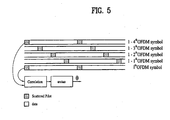
- FIG. 5 is a conceptual diagram illustrating a correlation algorithm using a scattered pilot according to the present invention.
- FIG. 6 is a block diagram illustrating an SFO estimation system using a scattered pilot according to the present invention.
- FIG. 7 is a flow chart illustrating an SFO estimation algorithm according to the present invention.
- FIG. 8a is a graph illustrating a phase variation in the case of using a scattered pilot according to the present invention.
- FIG. 8b is a graph illustrating a conventional phase variation in the case of using a CP
- FIG. 9 shows estimated SFO values when phase overshoots are zero-forced in a tracking mode according to the present invention.
- FIG. 10 is a block diagram illustrating an OFDM receiver according to the present invention.
- FIG. 4 shows a pilot insertion pattern according to the present invention
- Pilot arrangement shown in FIG. 4 is indicative of a predetermined pattern prescribed in a DVB-H transmission standard.
- the above-mentioned pilot arrangement is largely classified into a continual pilot (CP) arrangement and a scattered pilot arrangement, such that it is positioned between data subcarriers of an OFDM symbol.
- CP continual pilot
- scattered pilot arrangement such that it is positioned between data subcarriers of an OFDM symbol.
- the CP is located at the same subcarrier positiones as the above subcarrier positions in each OFDM symbol.
- the scattered pilot includes 12 subcarrier intervals, and is repeated at intervals of a predetermined time corresponding to four OFDM symbols.
- the scattered pilots may have many more phase information units than those of a CP, as can be seen from FIG. 4 .
- a constant interval is provided among the scattered pilots, resulting in less complexity in hardware implementation of the scattered pilots.
- each scattered pilot is delayed during four OFDM symbol intervals, and is then correlated with a current OFDM symbol, its detailed description will hereinafter be described with reference to FIG. 5 .
- FIG. 5 is a conceptual diagram illustrating a correlation algorithm using a scattered pilot according to the present invention.
- the scattered pilot has iterative patterns at intervals of a predetermined time corresponding to four OFDM symbols, such that it correlates a first OFDM symbol with first to fourth OFDM symbols generated when the first OFDM symbol is delayed four times.
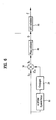
- FIG. 6 is a block diagram illustrating an SFO estimation system using a scattered pilot according to the present invention.
- the SFO estimation system receives a single signal of Z l,k .
- the Z l,k signal is indicative of a k-th pilot in a first OFDM symbol.
- the Z l,k signal is converted into a delayed signal of Z l- 4, k delayed for four symbol intervals via a "4 OFDM symbol delay" 10.
- the Z l -4, k signal is converted into a conjugate root signal of Z l ⁇ 4 , k ⁇ via a conjugate calculator 20.
- Correlation between the Z l,k signal and the Z l ⁇ 4 , k ⁇ signal is performed by a multiplier 30, such that the multiplier 30 outputs a phase information signal of x l,k .
- a phase estimator 40 calculates an arctangent value shown in Equation 1 using the above-mentioned phase information of x l,k , such that a total of 142 phase data units are acquired in the 2k mode and a total of 568 phase data units are acquired in the 8k mode.
- the SFO calculator 50 calculates an SFO value using the phase data acquired from the phase estimator 40, such that it estimates the SFO value.
- An algorithm for controlling the SFO calculator 50 to estimate the SFO value is shown in FIG. 7 .
- An SFO estimation method will hereinafter be described with reference to FIG. 7 .
- FIG. 7 is a flow chart illustrating an SFO estimation algorithm according to the present invention.
- the SFO calculator 50 determines whether a current frequency estimation mode is equal to a tracking mode at step S10.
- the phase ⁇ acquired from the phase estimator 40 is stored in a buffer contained in the SFO calculator 50 at step S20.
- the current frequency estimation mode is equal to the tracking mode at step S10, it is determined whether the estimated phase ⁇ is higher than an input standard deviation ⁇ ph at step S30.
- the magnitude of the standard deviation is experimentally set to 0.5rad.
- the magnitude of the estimated phase is higher than that of the standard deviation, it is determined that overshoots occur due to a deep fading phenomenon in the tracking mode, such that the estimated phase is compulsorily set to zero.
- the above-mentioned operation is called a zero-forcing operation.
- the estimated phase is compulsorily set to zero, such that the resultant estimated phase is stored in the buffer contained in the SFO calculator 50 at sep S40.
- the magnitude of the estimated phase is equal to or less than that of the standard deviation at step S30, it is determined that no overshoot occurs, such that the estimated phase is stored in the buffer contained in the SFO calculator 50 without any change.
- the phase estimator 40 correlates a pilot value prior to four symbols with a current pilot value to acquire a desired phase ⁇ , such that the phase ⁇ is collected during a single symbol interval.
- the collected phase value is classified into a left-half (LH) phase value and a right half (RH) phase value on the basis of a center subcarrier.
- the LH phase value and the RH phase value are accumulated to acquire accumulated phase values ( ⁇ RH , ⁇ LH ).
- an SFO value is calculated using a difference ( ⁇ RH - ⁇ LH ) between the accumulated phase values at step S60, as denoted by the following equation 2:
- the present invention employs many more pilots (i.e., 142 pilots in the 2k mode and 568 pilots in the 8k mode) than those (i.e., 45 pilots in the 2k mode and 177 pilots in the 8k mode) of the conventional CP-associated method, such that it acquires sufficient phase information, resulting in a more correct SFO value.
- pilots i.e., 142 pilots in the 2k mode and 568 pilots in the 8k mode
- those i.e., 45 pilots in the 2k mode and 177 pilots in the 8k mode
- FIG. 8a is a graph illustrating a phase variation in the case of using a scattered pilot according to the present invention.
- FIG. 8b is a graph illustrating a conventional phase variation in the case of using a CP.
- a single period of a saw-toothed phase graph shows a phase rotation amount generated during a single symbol interval. It can be recognized that the graph of FIG. 8a in which the scattered pilot is employed has less phase scattering as compared to the other graph of FIG. 8b in which the CP is employed. In other words, a line of the phase graph in FIG. 8a is more smooth than that of the phase graph in FIG. 8b . In this manner, if the degree of phase scattering is reduced, a more correct SFO can be estimated.
- FIG. 9 shows estimated SFO values when phase overshoots are zero-forced in the tracking mode for use in an SFO estimation algorithm using the scattered pilot according to the present invention.
- the jittering range reduction is acquired by zero-forcing phase overshoots in the tracking mode.
- the jittering range reduction in the tracking mode is indicative of ISI (Inter Symbol Interference) reduction of a reception signal, and no constellation rotation occurs in the tracking mode.
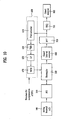
- FIG. 10 is a block diagram illustrating an OFDM receiver according to the present invention.
- the OFDM receiver includes an analog front-end and ADC (Analog-to-Digital Converter) unit 100, a P/S (Parallel-to-Serial) unit 200, a resampler 300, a guard interval removal unit 400, an FFT (Fast Fourier Transform) unit 500, an SFO compensator 600, an FEQ (Freuqency-domain Equalizer) unit 700, and a guard removal unit 800.
- the analog front-end and ADC unit 100 performs a front-end process on a received analog signal, and converts the received analog signal into a digital signal.
- the P/S unit 200 converts a received parallel signal into a serial signal.
- the resampler 300 performs a sampling process on a received signal using the sampling frequency generated by the estimated SFO.
- the guard interval removal unit 400 removes a guard interval of the received signal from a time domain.
- the FFT unit 500 converts a time-domain signal into a frequency-domain signal.
- the SFO compensator 600 performs correct sampling synchronization on the frequency-domain signal acting as the output signal of the FFT unit 500.
- the FEQ 700 performs channel equalization in a frequency domain.
- the guard remover unit 800 removes a guard interval from the frequency domain.
- the SFO compensator 600 includes a pilot extractor 610 for extracting a scattered pilot signal from the frequency-domain signal; a timing error detector 630 for receiving the extracted scattered pilot signal, and calculating a timing error value equal to the SFO value ⁇ using the extraction algorithm of the present invention; a loop filter (L/F) 650 for receiving the SFO value ⁇ , and accumulatively compensating for the received SFO value ⁇ ; and a numerical controlled oscillator (NCO) 670 for controlling a sampling frequency upon receiving the compensated SFO value ⁇ from the L/F 650.
- a pilot extractor 610 for extracting a scattered pilot signal from the frequency-domain signal
- a timing error detector 630 for receiving the extracted scattered pilot signal, and calculating a timing error value equal to the SFO value ⁇ using the extraction algorithm of the present invention
- L/F loop filter
- NCO numerical controlled oscillator
- the resampler 300 performs the sampling process using the resultant SFO value correctly estimated by the above-mentioned inventive method, such that correct sampling synchronization is provided.
- the present invention is applicable to a DVB-T receiver and a DVB-H receiver.
- a method and apparatus for estimating an SFO in a digital receiver according to the present invention has the following effects.
- an SFO value is estimated by the scattered pilot, such that it can be more correctly estimated than in the conventional SFO estimation method based on the CP.
- the jittering range caused by overshoots is reduced by a zero-forcing algorithm, such that an SFO estimation failure caused by serious phase distortion can be solved.
- correct sampling frequency compensation can be acquired by the estimated SFO value.
Landscapes
- Engineering & Computer Science (AREA)
- Signal Processing (AREA)
- Computer Networks & Wireless Communication (AREA)
- Multimedia (AREA)
- Synchronisation In Digital Transmission Systems (AREA)
- Train Traffic Observation, Control, And Security (AREA)
- Measurement And Recording Of Electrical Phenomena And Electrical Characteristics Of The Living Body (AREA)
- Developing Agents For Electrophotography (AREA)
Claims (20)
- Verfahren zum Schätzen eines Abtastfrequenzversatzes in einem digitalen Empfänger, um die Abtastsynchronisation durchzuführen, das die folgenden Schritte aufweist:a) Extrahieren eines aktuellen gestreuten Piloten mit einem Wiederholungsintervall von vier Symbolen, der in einem einzelnen orthogonalen Frequenzteilungsmultiplex-Symbolintervall enthalten ist;a1) Verzögern des extrahierten aktuellen gestreuten Piloten um vier Symbolintervalle;b) Berechnen eines Phasenwerts unter Verwendung sowohl des extrahierten aktuellen gestreuten Piloten als auch eines verzögerten gestreuten Piloten, der um vier Symbolintervalle gegen den aktuellen gesteuerten Piloten verzögert ist; undc) Schätzen (S60) eines Abtastfrequenzversatzwerts unter Verwendung des berechneten Phasenwerts.
- Verfahren nach Anspruch 1, wobei der Schritt b) zum Berechnen des Phasenwerts die folgenden Schritte umfaßt:b1) Korrelieren des aktuellen gestreuten Piloten mit dem Verzögerungswert, der gewonnen wird, wenn der aktuelle gestreute Pilot um vier Symbolintervalle verzögert ist; undb2) Durchführen einer Arcustangens-Operation für den sich ergebenden Korrelationswert, um eine gewünschte Phase zu gewinnen.
- Verfahren nach Anspruch 1, wobei der Schritt c) zum Schätzen des Abtastfrequenzversatzwerts die folgenden Schritte umfaßt:c1) Empfangen des geschätzten Phasenwerts und Bestimmen des Vorhandenseins oder Nichtvorhandenseins von Phasenüberschreitungen auf der Basis des empfangenen Phasenwerts;c2) wenn die Phasenüberschreitungen auftreten, zwangsweises Festlegten des geschätzten Phasenwerts auf null und Speichern des sich ergebenden Phasenwerts; undc3) Berechnen des Abtastfrequenzversatzwerts unter Verwendung des gespeicherten Phasenwerts.
- Verfahren nach Anspruch 3, wobei der Schritt c1) zum Bestimmen des Vorhandenseins oder Nichtvorhandenseins der Phasenüberschreitungen den folgenden Schritt umfaßt:Vergleichen der Größe des geschätzten Phasenwerts mit dem einer vorgegebenen Standardabweichung und Bestimmen des Vorhandenseins oder Nichtvorhandenseins der Phasenüberschreitungen gemäß dem Vergleichsergebnis.
- Verfahren nach Anspruch 4, wobei die vorgegebene Standardabweichung 0,5 rad beträgt.
- Verfahren nach Anspruch 3, wobei der Schritt c1) zum Bestimmen des Vorhandenseins oder Nichtvorhandenseins der Phasenüberschreitungen durchgeführt wird, wenn ein Schätzbetrieb für die aktuelle Frequenz ein Frequenzverfolgungsbetrieb ist.
- Verfahren nach Anspruch 6, das ferner den folgenden Schritt aufweist:wenn der Frequenzschätzbetrieb nicht gleich dem Frequenzverfolgungsbetrieb ist, Speichern des geschätzten Phasenwerts in einen Puffer und Berechnen des Abtastfrequenzversatzwerts unter Verwendung des gespeicherten Phasenwerts.
- Verfahren nach Anspruch 3, das ferner den folgenden Schritt aufweist:wenn keine Phasenüberschreitung bestimmt wird, Speichern der geschätzten Phase und Berechnen des Abtastfrequenzversatzwerts unter Verwendung des gespeicherten Phasenwerts.
- Verfahren nach Anspruch 3, wobei der Schritt c3) zum Berechnen des Abtastfrequenzversatzwerts die folgenden Schritte aufweist:c3-1) Teilen des gespeicherten Phasenwerts in einen Phasenwert der linken Hälfte (LH) und einen Phasenwert der rechten Hälfte (RH) auf der Basis eines zentralen Teilträgers; und jeweils Akkumulieren des LH-Phasenwerts und des RH-Phasenwerts; undc3-2) Berechnen einer Differenz zwischen den akkumulierten LH- und RH-Phasenwerten und Berechnen des Abtastfrequenzversatzwerts.
- Verfahren nach Anspruch 9, wobei die Abtastfrequenzversatzberechnung in einer einzigen Symbolintervalleinheit durchgeführt wird.
- Vorrichtung zum Schätzen eines Abtastfrequenzversatzes in einem digitalen Empfänger, die aufweist:eine Verzögerungseinrichtung zum Empfangen eines gestreuten Piloten mit einem Wiederholungsintervall von vier Symbolen, der in einem einzelnen orthogonalen Frequenzteilungsmultiplex-Symbolintervall enthalten ist, und Verzögern des empfangenen gestreuten Piloten um vier Symbolintervalle;einen Phasenschätzer (40) zum Empfangen eines aktuellen gestreuten Piloten, der in einem orthogonalen Frequenzteilungsmultiplex-Symbolintervall enthalten ist, und Schätzen eines Phasenwerts sowohl unter Verwendung des aktuellen gestreuten Piloten als auch eines verzögerten gestreuten Piloten, der um vier Symbolintervalle gegen den aktuellen gesteuerten Piloten verzögert ist; undeine Abtastfrequenzversatz-Berechnungseinrichtung (50) zum Berechnen eines Abtastfrequenzversatzwerts unter Verwendung des geschätzten Phasenwerts.
- Vorrichtung nach Anspruch 11, die aufweist:eine Konjugiertenberechnungsvorrichtung zum Berechnen eines konjugierten Wurzelwerts eines Ausgangswerts der Verzögerung;einen Multiplizierer zum Korrelieren eines Ausgangswerts der Konjugiertenberechnungsvorrichtung mit dem empfangenen gestreuten Piloten;einen Phasenschätzer zum Durchführen einer Arcustangens-Operation für einen Ausgangswert des Multiplizierers, um einen Phasenwert zu gewinnen; undeine Abtastfrequenzversatz-Berechnungseinrichtung zum Empfangen eines Ausgangswerts des Phasenschätzers, Speichern des empfangenen Ausgangswerts des Phasenschätzers während eines vorgegebenen Intervalls und Berechnen eines Abtastfrequenzversatzwerts unter Verwendung des gespeicherten Werts.
- Vorrichtung nach Anspruch 12, wobei die Abtastfrequenzversatz-Berechnungseinrichtung das Vorhandensein oder Nichtvorhandensein von Phasenüberschreitungen in einem Verfolgungsbetrieb einer Abtastfrequenz bestimmt und eine Nullerzwingungsoperation durchführt, wenn das Vorhandensein der Phasenüberschreitungen bestimmt wird.
- Vorrichtung nach Anspruch 13, wobei das Vorhandensein oder Nichtvorhandensein der Phasenüberschreitungen durch Vergleichen des geschätzten Phasenwerts mit einer vorgegebenen Standardabweichung bestimmt wird.
- Vorrichtung nach Anspruch 14, wobei die vorgegebene Standardabweichung 0,5 rad beträgt.
- Vorrichtung nach Anspruch 12, wobei die Abtastfrequenzversatzberechnung unter Verwendung des geschätzten Phasenwerts in einer einzigen Symbolintervalleinheit durchgeführt wird.
- Vorrichtung nach Anspruch 12, wobei die Abtastfrequenzversatz-Berechnungseinrichtung den gespeicherten Phasenwert auf der Basis eines zentralen Teilträgers in einen Phasenwert der linken Hälfte und einen Phasenwert der rechten Hälfte teilt, jeweils den Phasenwert der linken Hälfte und den Phasenwert der rechten Hälfte akkumuliert, eine Differenz zwischen den akkumulierten Phasenwerten der linken Hälfte und der rechten Hälfte berechnet und den Abtastfrequenzversatzwert berechnet.
- Vorrichtung nach Anspruch 11, die aufweist:einen Wiederholungsabtaster zum Durchführen eines Abtastverfahrens an einem Empfangssignal gemäß dem berechneten Abtastfrequenzversatzwert;eine Schutzintervall-Entfernungseinheit zum Entfernen eines Schutzintervalls des Empfangssignals aus einer Zeitdomäne;eine Schnelle-Fouriertransformationseinheit (FFT-Einheit) zum Umwandeln des Zeitdomänensignals in ein Frequenzdomänensignal; undeinen Abtastfrequenzversatzkompensator zum Berechnen des Abtastfrequenzversatzwerts unter Verwendung eines gestreuten Piloten, der in einem orthogonalen Frequenzteilungsmultiplex- (orthogonalen Frequenzdomänenmultiplex-) Symbol enthalten ist, um die korrekte Abtastsynchronisation für das Frequenzdomänensignal durchzuführen.
- Vorrichtung nach Anspruch 18, wobei der Abtastfrequenzversatzkompensator umfaßt:eine Pilotenextraktionsvorrichtung zum Extrahieren eines gesteuerten Pilotsignals aus dem Frequenzdomänensignal;einen Zeitablauffehlerdetektor zum Empfangen des extrahierten gestreuten Pilotsignals, Schätzen eines Phasenwerts unter Verwendung sowohl des gestreuten Piloten, der in einem einzelnen Symbol enthalten ist, als auch eines Verzögerungswerts, der gewonnen wird, wenn der verzögerte Pilot um vier Symbolintervalle verzögert ist, und zum Berechnen des Abtastfrequenzversatzwerts unter Verwendung des geschätzten Phasenwerts;ein Schleifenfilter (L/F) zum Empfangen des Abtastfrequenzversatzwerts und akkumulativen Kompensieren des empfangenen Abtastfrequenzversatzwerts; undeinen numerisch gesteuerten Oszillator (NCO) zum Steuern einer Abtastfrequenz nach Empfang des kompensierten Abtastfrequenzversatzwerts von der L/F-Einheit.
- Vorrichtung nach Anspruch 18, wobei der digitale Empfänger ein digitales terrestrisches Videoausstrahlungssystem oder ein digitales Videoausstrahlungsmobilsystem ist.
Applications Claiming Priority (1)
| Application Number | Priority Date | Filing Date | Title |
|---|---|---|---|
| KR1020040065130A KR101080969B1 (ko) | 2004-08-18 | 2004-08-18 | 디지털 수신기의 sfo 추정 방법 및 장치 |
Publications (3)
| Publication Number | Publication Date |
|---|---|
| EP1633098A2 EP1633098A2 (de) | 2006-03-08 |
| EP1633098A3 EP1633098A3 (de) | 2007-10-03 |
| EP1633098B1 true EP1633098B1 (de) | 2010-08-04 |
Family
ID=35520135
Family Applications (1)
| Application Number | Title | Priority Date | Filing Date |
|---|---|---|---|
| EP05291741A Ceased EP1633098B1 (de) | 2004-08-18 | 2005-08-17 | Trägersynchronisation in OFDM |
Country Status (5)
| Country | Link |
|---|---|
| US (1) | US20060039515A1 (de) |
| EP (1) | EP1633098B1 (de) |
| KR (1) | KR101080969B1 (de) |
| AT (1) | ATE476816T1 (de) |
| DE (1) | DE602005022656D1 (de) |
Families Citing this family (11)
| Publication number | Priority date | Publication date | Assignee | Title |
|---|---|---|---|---|
| TWI335164B (en) * | 2007-03-20 | 2010-12-21 | Ind Tech Res Inst | Timing-offset estimator and method thereof in ofdm systems |
| CN101277284B (zh) * | 2007-03-29 | 2012-12-26 | 深圳赛意法微电子有限公司 | 在drm中的采样时钟频率偏移量估计的方法及集成芯片 |
| US20080273646A1 (en) * | 2007-05-02 | 2008-11-06 | Mediaphy Corporation | Sampling clock offset tracking and symbol re-timing |
| US7801020B2 (en) * | 2007-08-29 | 2010-09-21 | Intel Corporation | Mobile channel estimation algorithm for DVB-H COFDM demodulator |
| US8085860B2 (en) * | 2008-04-29 | 2011-12-27 | Hong Kong Applied Science And Technology Research Institute Co., Ltd. | Systems and methods for sampling frequency offset estimation |
| CN102480457B (zh) * | 2010-11-30 | 2014-06-11 | 中兴通讯股份有限公司 | Ofdma系统的频偏补偿方法及装置 |
| JP6703364B2 (ja) * | 2014-04-10 | 2020-06-03 | ザインエレクトロニクス株式会社 | 受信装置 |
| US9246734B1 (en) * | 2015-02-27 | 2016-01-26 | Qualcomm Technologies International, Ltd. | Method and apparatus for sample frequency offset correction OFDM and single carrier frequency domain equalized receiver systems |
| FR3059183B1 (fr) * | 2016-11-24 | 2019-02-01 | Continental Automotive France | Demodulation optimisee des signaux rds en radio numerique |
| CN111817841B (zh) * | 2020-06-08 | 2023-03-21 | 深圳友讯达科技股份有限公司 | 适用于低信噪比的盲时序误差检测方法、系统及存储介质 |
| CN121441703A (zh) * | 2025-12-31 | 2026-01-30 | 国网安徽省电力有限公司信息通信分公司 | 基于频域时域结合的无人机动态sfo补偿方法及系统 |
Family Cites Families (4)
| Publication number | Priority date | Publication date | Assignee | Title |
|---|---|---|---|---|
| GB2325126B (en) * | 1997-05-02 | 2002-06-19 | Lsi Logic Corp | Demodulating digital video broadcast signals |
| KR100402906B1 (ko) * | 2001-02-08 | 2003-10-22 | (주)아이앤씨테크놀로지 | 직교주파수분할다중방식에서의 주파수 오프셋 동기화 장치및 방법 |
| US7418026B2 (en) * | 2002-05-09 | 2008-08-26 | Sony United Kingdom Limited | Receiver for a multi-carrier modulated symbol |
| US7388847B2 (en) * | 2003-08-18 | 2008-06-17 | Nortel Networks Limited | Channel quality indicator for OFDM |
-
2004
- 2004-08-18 KR KR1020040065130A patent/KR101080969B1/ko not_active Expired - Fee Related
-
2005
- 2005-08-17 US US11/205,671 patent/US20060039515A1/en not_active Abandoned
- 2005-08-17 DE DE602005022656T patent/DE602005022656D1/de not_active Expired - Lifetime
- 2005-08-17 AT AT05291741T patent/ATE476816T1/de not_active IP Right Cessation
- 2005-08-17 EP EP05291741A patent/EP1633098B1/de not_active Ceased
Also Published As
| Publication number | Publication date |
|---|---|
| EP1633098A2 (de) | 2006-03-08 |
| KR20060016623A (ko) | 2006-02-22 |
| ATE476816T1 (de) | 2010-08-15 |
| KR101080969B1 (ko) | 2011-11-09 |
| DE602005022656D1 (de) | 2010-09-16 |
| EP1633098A3 (de) | 2007-10-03 |
| US20060039515A1 (en) | 2006-02-23 |
Similar Documents
| Publication | Publication Date | Title |
|---|---|---|
| CN101507219B (zh) | 数据符号的时间误差估计方法和系统 | |
| US7649963B2 (en) | Apparatus for estimating and compensating carrier frequency offset and data receiving method in receiver of wireless communication system | |
| JP4164364B2 (ja) | 複雑さが低減したチャンネル応答推定を有するマルチキャリヤ伝送システム | |
| US7133479B2 (en) | Frequency synchronization apparatus and method for OFDM systems | |
| US8406322B2 (en) | OFDM demodulation device and method | |
| Liu et al. | A study of joint tracking algorithms of carrier frequency offset and sampling clock offset for OFDM-based WLANs | |
| US8437426B2 (en) | Receiving apparatus, receiving method, and program | |
| EP0896457A1 (de) | Symbolsynchronisierung für Mehrträgersignalen mit Schutzintervall | |
| WO2008137840A1 (en) | Ofdm-based device and method for performing synchronization | |
| EP1628450A2 (de) | Einrichtung zur Frequenzrückgewinnung und mobiler Rundfunkempfänger mit einer solchen Einrichtung | |
| EP1133841A1 (de) | System und verfahren zur kompensation von zeitfehlern durch ein pilotsymbol in einem ofdm/cdma kommunikationssystem | |
| EP2245816B1 (de) | Post-DFT/FFT-Zeitverfolgungsalgorithmus für OFDM-empfänger | |
| US20030058953A1 (en) | Receiver of an orthogonal frequency division multiplexing system | |
| KR20070056881A (ko) | 직교 주파수 다중 접속 시스템에서의 주파수 복원 장치 및방법 | |
| EP1633098B1 (de) | Trägersynchronisation in OFDM | |
| JP4961918B2 (ja) | Ofdm受信装置及びofdm受信方法 | |
| US7792202B2 (en) | Apparatus and method for estimating timing offset of OFDM symbol, and method of recovering symbol timing of OFDM symbol | |
| US7573953B2 (en) | Method and apparatus for estimating SFO in digital receiver, and method and apparatus for compensating for sampling frequency using the estimated SFO in the digital receiver | |
| WO2006111275A2 (en) | Initial parameter estimation in ofdm systems | |
| JP2009519664A (ja) | 広帯域伝送システムにおいてシンボル時間誤差を推定する方法およびシステム | |
| WO2007072348A2 (en) | A method for signal reception in a ofdm system | |
| US7869495B2 (en) | OFDM receiver using time-domain and frequency-domain equalizing and time domain equalizer | |
| EP1387544B1 (de) | Synchronisierung in Mehrträgerempfängern | |
| KR100746553B1 (ko) | 직교 주파수 분할 다중화 시스템을 위한 반송파 주파수 오차 기반의 시간 오차 추정 장치 및 그 방법 | |
| CN102123126A (zh) | 数字接收机的公共相位误差纠正方法和装置 |
Legal Events
| Date | Code | Title | Description |
|---|---|---|---|
| PUAI | Public reference made under article 153(3) epc to a published international application that has entered the european phase |
Free format text: ORIGINAL CODE: 0009012 |
|
| 17P | Request for examination filed |
Effective date: 20050823 |
|
| AK | Designated contracting states |
Kind code of ref document: A2 Designated state(s): AT BE BG CH CY CZ DE DK EE ES FI FR GB GR HU IE IS IT LI LT LU LV MC NL PL PT RO SE SI SK TR |
|
| AX | Request for extension of the european patent |
Extension state: AL BA HR MK YU |
|
| PUAL | Search report despatched |
Free format text: ORIGINAL CODE: 0009013 |
|
| AK | Designated contracting states |
Kind code of ref document: A3 Designated state(s): AT BE BG CH CY CZ DE DK EE ES FI FR GB GR HU IE IS IT LI LT LU LV MC NL PL PT RO SE SI SK TR |
|
| AX | Request for extension of the european patent |
Extension state: AL BA HR MK YU |
|
| 17Q | First examination report despatched |
Effective date: 20080415 |
|
| AKX | Designation fees paid |
Designated state(s): AT BE BG CH CY CZ DE DK EE ES FI FR GB GR HU IE IS IT LI LT LU LV MC NL PL PT RO SE SI SK TR |
|
| GRAP | Despatch of communication of intention to grant a patent |
Free format text: ORIGINAL CODE: EPIDOSNIGR1 |
|
| GRAS | Grant fee paid |
Free format text: ORIGINAL CODE: EPIDOSNIGR3 |
|
| GRAA | (expected) grant |
Free format text: ORIGINAL CODE: 0009210 |
|
| AK | Designated contracting states |
Kind code of ref document: B1 Designated state(s): AT BE BG CH CY CZ DE DK EE ES FI FR GB GR HU IE IS IT LI LT LU LV MC NL PL PT RO SE SI SK TR |
|
| REG | Reference to a national code |
Ref country code: GB Ref legal event code: FG4D |
|
| REG | Reference to a national code |
Ref country code: CH Ref legal event code: EP |
|
| REG | Reference to a national code |
Ref country code: IE Ref legal event code: FG4D |
|
| REF | Corresponds to: |
Ref document number: 602005022656 Country of ref document: DE Date of ref document: 20100916 Kind code of ref document: P |
|
| REG | Reference to a national code |
Ref country code: NL Ref legal event code: VDEP Effective date: 20100804 |
|
| LTIE | Lt: invalidation of european patent or patent extension |
Effective date: 20100804 |
|
| PG25 | Lapsed in a contracting state [announced via postgrant information from national office to epo] |
Ref country code: LT Free format text: LAPSE BECAUSE OF FAILURE TO SUBMIT A TRANSLATION OF THE DESCRIPTION OR TO PAY THE FEE WITHIN THE PRESCRIBED TIME-LIMIT Effective date: 20100804 Ref country code: FI Free format text: LAPSE BECAUSE OF FAILURE TO SUBMIT A TRANSLATION OF THE DESCRIPTION OR TO PAY THE FEE WITHIN THE PRESCRIBED TIME-LIMIT Effective date: 20100804 Ref country code: NL Free format text: LAPSE BECAUSE OF FAILURE TO SUBMIT A TRANSLATION OF THE DESCRIPTION OR TO PAY THE FEE WITHIN THE PRESCRIBED TIME-LIMIT Effective date: 20100804 Ref country code: AT Free format text: LAPSE BECAUSE OF FAILURE TO SUBMIT A TRANSLATION OF THE DESCRIPTION OR TO PAY THE FEE WITHIN THE PRESCRIBED TIME-LIMIT Effective date: 20100804 |
|
| PG25 | Lapsed in a contracting state [announced via postgrant information from national office to epo] |
Ref country code: IS Free format text: LAPSE BECAUSE OF FAILURE TO SUBMIT A TRANSLATION OF THE DESCRIPTION OR TO PAY THE FEE WITHIN THE PRESCRIBED TIME-LIMIT Effective date: 20101204 Ref country code: BG Free format text: LAPSE BECAUSE OF FAILURE TO SUBMIT A TRANSLATION OF THE DESCRIPTION OR TO PAY THE FEE WITHIN THE PRESCRIBED TIME-LIMIT Effective date: 20101104 Ref country code: CY Free format text: LAPSE BECAUSE OF FAILURE TO SUBMIT A TRANSLATION OF THE DESCRIPTION OR TO PAY THE FEE WITHIN THE PRESCRIBED TIME-LIMIT Effective date: 20100804 Ref country code: PT Free format text: LAPSE BECAUSE OF FAILURE TO SUBMIT A TRANSLATION OF THE DESCRIPTION OR TO PAY THE FEE WITHIN THE PRESCRIBED TIME-LIMIT Effective date: 20101206 Ref country code: PL Free format text: LAPSE BECAUSE OF FAILURE TO SUBMIT A TRANSLATION OF THE DESCRIPTION OR TO PAY THE FEE WITHIN THE PRESCRIBED TIME-LIMIT Effective date: 20100804 Ref country code: SI Free format text: LAPSE BECAUSE OF FAILURE TO SUBMIT A TRANSLATION OF THE DESCRIPTION OR TO PAY THE FEE WITHIN THE PRESCRIBED TIME-LIMIT Effective date: 20100804 |
|
| PG25 | Lapsed in a contracting state [announced via postgrant information from national office to epo] |
Ref country code: MC Free format text: LAPSE BECAUSE OF NON-PAYMENT OF DUE FEES Effective date: 20100831 Ref country code: GR Free format text: LAPSE BECAUSE OF FAILURE TO SUBMIT A TRANSLATION OF THE DESCRIPTION OR TO PAY THE FEE WITHIN THE PRESCRIBED TIME-LIMIT Effective date: 20101105 Ref country code: LV Free format text: LAPSE BECAUSE OF FAILURE TO SUBMIT A TRANSLATION OF THE DESCRIPTION OR TO PAY THE FEE WITHIN THE PRESCRIBED TIME-LIMIT Effective date: 20100804 Ref country code: SE Free format text: LAPSE BECAUSE OF FAILURE TO SUBMIT A TRANSLATION OF THE DESCRIPTION OR TO PAY THE FEE WITHIN THE PRESCRIBED TIME-LIMIT Effective date: 20100804 Ref country code: BE Free format text: LAPSE BECAUSE OF FAILURE TO SUBMIT A TRANSLATION OF THE DESCRIPTION OR TO PAY THE FEE WITHIN THE PRESCRIBED TIME-LIMIT Effective date: 20100804 |
|
| REG | Reference to a national code |
Ref country code: CH Ref legal event code: PL |
|
| PG25 | Lapsed in a contracting state [announced via postgrant information from national office to epo] |
Ref country code: LI Free format text: LAPSE BECAUSE OF NON-PAYMENT OF DUE FEES Effective date: 20100831 Ref country code: DK Free format text: LAPSE BECAUSE OF FAILURE TO SUBMIT A TRANSLATION OF THE DESCRIPTION OR TO PAY THE FEE WITHIN THE PRESCRIBED TIME-LIMIT Effective date: 20100804 Ref country code: CH Free format text: LAPSE BECAUSE OF NON-PAYMENT OF DUE FEES Effective date: 20100831 |
|
| PG25 | Lapsed in a contracting state [announced via postgrant information from national office to epo] |
Ref country code: SK Free format text: LAPSE BECAUSE OF FAILURE TO SUBMIT A TRANSLATION OF THE DESCRIPTION OR TO PAY THE FEE WITHIN THE PRESCRIBED TIME-LIMIT Effective date: 20100804 Ref country code: CZ Free format text: LAPSE BECAUSE OF FAILURE TO SUBMIT A TRANSLATION OF THE DESCRIPTION OR TO PAY THE FEE WITHIN THE PRESCRIBED TIME-LIMIT Effective date: 20100804 Ref country code: EE Free format text: LAPSE BECAUSE OF FAILURE TO SUBMIT A TRANSLATION OF THE DESCRIPTION OR TO PAY THE FEE WITHIN THE PRESCRIBED TIME-LIMIT Effective date: 20100804 Ref country code: RO Free format text: LAPSE BECAUSE OF FAILURE TO SUBMIT A TRANSLATION OF THE DESCRIPTION OR TO PAY THE FEE WITHIN THE PRESCRIBED TIME-LIMIT Effective date: 20100804 |
|
| PLBE | No opposition filed within time limit |
Free format text: ORIGINAL CODE: 0009261 |
|
| STAA | Information on the status of an ep patent application or granted ep patent |
Free format text: STATUS: NO OPPOSITION FILED WITHIN TIME LIMIT |
|
| PG25 | Lapsed in a contracting state [announced via postgrant information from national office to epo] |
Ref country code: ES Free format text: LAPSE BECAUSE OF FAILURE TO SUBMIT A TRANSLATION OF THE DESCRIPTION OR TO PAY THE FEE WITHIN THE PRESCRIBED TIME-LIMIT Effective date: 20101115 |
|
| 26N | No opposition filed |
Effective date: 20110506 |
|
| PG25 | Lapsed in a contracting state [announced via postgrant information from national office to epo] |
Ref country code: IE Free format text: LAPSE BECAUSE OF NON-PAYMENT OF DUE FEES Effective date: 20100817 |
|
| REG | Reference to a national code |
Ref country code: DE Ref legal event code: R097 Ref document number: 602005022656 Country of ref document: DE Effective date: 20110506 |
|
| PG25 | Lapsed in a contracting state [announced via postgrant information from national office to epo] |
Ref country code: LU Free format text: LAPSE BECAUSE OF NON-PAYMENT OF DUE FEES Effective date: 20100817 Ref country code: HU Free format text: LAPSE BECAUSE OF FAILURE TO SUBMIT A TRANSLATION OF THE DESCRIPTION OR TO PAY THE FEE WITHIN THE PRESCRIBED TIME-LIMIT Effective date: 20110205 |
|
| PG25 | Lapsed in a contracting state [announced via postgrant information from national office to epo] |
Ref country code: TR Free format text: LAPSE BECAUSE OF FAILURE TO SUBMIT A TRANSLATION OF THE DESCRIPTION OR TO PAY THE FEE WITHIN THE PRESCRIBED TIME-LIMIT Effective date: 20100804 |
|
| REG | Reference to a national code |
Ref country code: FR Ref legal event code: PLFP Year of fee payment: 11 |
|
| REG | Reference to a national code |
Ref country code: FR Ref legal event code: PLFP Year of fee payment: 12 |
|
| REG | Reference to a national code |
Ref country code: FR Ref legal event code: PLFP Year of fee payment: 13 |
|
| PGFP | Annual fee paid to national office [announced via postgrant information from national office to epo] |
Ref country code: GB Payment date: 20170707 Year of fee payment: 13 Ref country code: DE Payment date: 20170705 Year of fee payment: 13 Ref country code: FR Payment date: 20170707 Year of fee payment: 13 Ref country code: IT Payment date: 20170809 Year of fee payment: 13 |
|
| REG | Reference to a national code |
Ref country code: DE Ref legal event code: R119 Ref document number: 602005022656 Country of ref document: DE |
|
| GBPC | Gb: european patent ceased through non-payment of renewal fee |
Effective date: 20180817 |
|
| PG25 | Lapsed in a contracting state [announced via postgrant information from national office to epo] |
Ref country code: IT Free format text: LAPSE BECAUSE OF NON-PAYMENT OF DUE FEES Effective date: 20180817 Ref country code: DE Free format text: LAPSE BECAUSE OF NON-PAYMENT OF DUE FEES Effective date: 20190301 |
|
| PG25 | Lapsed in a contracting state [announced via postgrant information from national office to epo] |
Ref country code: FR Free format text: LAPSE BECAUSE OF NON-PAYMENT OF DUE FEES Effective date: 20180831 |
|
| PG25 | Lapsed in a contracting state [announced via postgrant information from national office to epo] |
Ref country code: GB Free format text: LAPSE BECAUSE OF NON-PAYMENT OF DUE FEES Effective date: 20180817 |