EP1632792B1 - Thermolumineszenzmessungen und Dosimetrie mit Temperaturkontrolle des Thermolunineszenzelements - Google Patents
Thermolumineszenzmessungen und Dosimetrie mit Temperaturkontrolle des Thermolunineszenzelements Download PDFInfo
- Publication number
- EP1632792B1 EP1632792B1 EP05019007A EP05019007A EP1632792B1 EP 1632792 B1 EP1632792 B1 EP 1632792B1 EP 05019007 A EP05019007 A EP 05019007A EP 05019007 A EP05019007 A EP 05019007A EP 1632792 B1 EP1632792 B1 EP 1632792B1
- Authority
- EP
- European Patent Office
- Prior art keywords
- tld
- heating
- radiation
- laser
- temperature
- Prior art date
- Legal status (The legal status is an assumption and is not a legal conclusion. Google has not performed a legal analysis and makes no representation as to the accuracy of the status listed.)
- Expired - Lifetime
Links
Images


Classifications
-
- G—PHYSICS
- G01—MEASURING; TESTING
- G01T—MEASUREMENT OF NUCLEAR OR X-RADIATION
- G01T1/00—Measuring X-radiation, gamma radiation, corpuscular radiation, or cosmic radiation
- G01T1/02—Dosimeters
- G01T1/10—Luminescent dosimeters
- G01T1/11—Thermo-luminescent dosimeters
-
- G—PHYSICS
- G01—MEASURING; TESTING
- G01T—MEASUREMENT OF NUCLEAR OR X-RADIATION
- G01T1/00—Measuring X-radiation, gamma radiation, corpuscular radiation, or cosmic radiation
- G01T1/02—Dosimeters
- G01T1/10—Luminescent dosimeters
- G01T1/11—Thermo-luminescent dosimeters
- G01T1/115—Read-out devices
Definitions
- the present invention relates generally to dosimeter systems for monitoring radiation from such radiation sources as ultraviolet, X-ray radiation, gamma radiation, beta radiation, and neutrons, and more particularly to thermoluminescence measurements and dosimetry.
- Radiotherapy dosimeters which measure the dose of incident radiation to which people, animals, plants or inanimate objects are exposed, are known. Dosimeters have been used in prior art for personal and environmental monitoring, for medical research and for radiation therapy. Of particular interest are small dosimeters, which are worn as personal badges and which need to be reliable and accurate, especially for measurements of low radiation doses. Some of these dosimeters are based on disposable photographic films. Others are non - disposable, such as those based on optically stimulated luminescence. Thermoluminescent dosimeters are among the most important non - disposable personal dosimeters, and may be used for example for in vivo and environmental dosimetry.
- Thermoluminescence is a physical phenomenon exhibited in materials which are irradiated with energetic radiation and subsequently stimulated, using heat, to produce luminescent emission.
- thermoluminescent materials are exposed to a flux of electromagnetic radiation such as gamma rays, X-rays or UV rays, to charged particles such as beta rays, to uncharged particles such as neutrons, or to other forms of radiation, electrons within the material are excited from low energy levels to relatively stable traps at higher energy levels. The electrons may stay at these higher energy levels for a long period of time. If the material is heated, the added energy releases the trapped electrons, causing them to fall back to the lower energy levels. This fall is accompanied by the emission of a luminescent emission, i.e. thermoluminescence.
- thermoluminescence dosimetry TLD
- TLD time division multiplex detection and spectroscopy
- the badge may comprise more than one TLD element.
- the badge is assumed to receive the same dose as the carrying person. Periodically, the badges are processed to obtain an exposure record for each person being monitored.
- TLD elements If glow curve measurements are carried out on TLD elements, reliable results are obtained only when each of these elements is heated in a controllable and reproducible fashion (i.e. using the same initial and final temperatures and the same variation of temperature with time).
- TLD elements Different materials have been used for TL dosimetry (and for making TLD elements). These include Na 2 SO 4 MgSO 4 , Y 2 O 3 , Al 2 O 3 , CaF 2 , SrF 2 and BaF 2 , doped materials, such as CaSO 4 :Tm, CaF 2 :Mn, Al 2 O 3 :C, LiF:Cu, Mg, Pr, as well as many other materials.
- the TLD elements are normally made from single crystals, from pressed powders, from thin layers deposited on substrates, from small particles embedded in glass or in polymers, etc. In some cases the elements are exposed (uncased) during the TL measurement.
- each element is placed within a tiny plastic bag, which is part of the personal badge, so that the heating and the luminescence measurements can be carried out without removing the element from the plastic bag.
- the TLD elements may have different geometrical shapes, e.g. plates, discs, rods, pellets, fibers, etc. Several methods have been used in the past for heating the TLD elements:
- Exemplary methods and systems may be found in a number of prior art publications, for example in US patents 3,531,641 , 3,729,630 , 3,975,637 , 4,204,119 , 4,638,163 , 4,835,388 , 4,839,518 , 5,041,734 , 5,081,363 , 5,606,163 , 6,005,231 and 6,414,324 . None of these methods and systems measures the temperature of the TLD element in real time to enable accurate control of the TLD heating rate.
- US Patent No. 6,005,231 discloses a method and apparatus for measuring radiation doses based upon thermoluminescence.
- a heat energy sensor is provided for the heat source for detecting the heat energy output from the heat source toward the element.
- the temperature of the element is calculated on the basis of the detected heat energy.
- the calculated temperature is used to determine if remedial action is necessary. For instance, the calculated temperature may be compared with a predetermined optimum heating temperature. If the calculated temperature deviates from the predetermined optimum heating temperature, responsive action is taken.
- a temperature increase rate may also be calculated. The calculated increase rate would be compared with a predetermined heating rate. The heating device would increase its heat energy output if the calculated increase rate is lower than the predetermined heating rate and decrease the heat energy if the calculated increase rate is higher than the predetermined heating rate.
- the inventors do not measure directly the temperature of the TLD element, and in fact state that it is almost impossible to measure the temperature of the TLD element during heating.
- thermocouple may be placed in contact with the TLD element to provide a T el measurement.
- T el may vary between elements and may change in time for the same element, such temperature measurements are inaccurate. This remains a common problem in all TLD systems. Consequently, even if the heating source behaves reproducibly, the real heating rate of the TLD elements may not be reproducible.
- the temperature T el of the TLD element can be determined by measuring the thermal infrared radiation emitted from its surface.
- thermal radiation of a body near room temperature is in the middle infrared (mid-IR) in the spectral range 3-30 ⁇ m.
- This radiation can be easily measured by infrared detectors, which may exemplarily be thermal detectors, such as pyroelectric, thermoresistive and MEMS devices, many of whom operate at room temperature, or photonic (i.e. quantum) detectors such as HgCdTe, many of whom are cooled by liquid nitrogen or thermoelectrically.
- thermal detectors such as pyroelectric, thermoresistive and MEMS devices, many of whom operate at room temperature, or photonic (i.e. quantum) detectors such as HgCdTe, many of whom are cooled by liquid nitrogen or thermoelectrically.
- photonic detectors such as HgCdTe
- the mid-IR radiation emitted from the surface of the TLD element can be collected and focused on the infrared detector using standard optical elements, such as mirrors or lenses.
- the emitted mid - IR radiation can also be carried through infrared transmitting optical fibers, only a few of which are transparent in the mid-IR range.
- Optical fibers made of silver halides are among the best candidates for that purpose. They are highly transparent in the mid-infrared, in the spectral range 3 30 m, with losses of about 0.2dB/m at 10.6 m.
- IR temperature measurements based on detection of IR radiation emitted by a heated body are known, see e.g. Remote IR sensing of temperature, including through the use of fibers that conduct the IR radiation to a detector, is also known, see e.g. S. Sade, O. Eyal, V. Scharf and A. Katzir, "Fiberoptic Infrared Radiometer for Accurate Temperature Measurements," Applied Optics, Vol. 41, no. 10, pp. 1908-1914 (2002) .
- S. Sade O. Eyal, V. Scharf and A. Katzir
- S. Sade O. Eyal, V. Scharf and A. Katzir
- US-A-3 790 784 discloses a method and apparatus for treating thermoluminescent dosimeters to enable read-out of the dosimeters and to permit their prompt reuse by eliminating the conventional annealing cycle.
- the dosimeter is initially preheated to a first temperature and is maintained at that temperature for a predetermined time.
- the dosimeter is then heated to a second read-out temperature and is maintained at the read-out temperature for a selected time interval.
- the dosimeter is then immediately heated further to an annealing temperature which is maintained for a selected interval, followed by cooling of the dosimeter whereby the dosimeter can again be promptly reused for accurately determining radiation dosage without the necessity of subjecting the dosimeter to the conventional and lengthy annealing cycle.
- US-A-4 906 848 discloses apparatuses and methods for rapidly reading phosphors to determine the amount of energy stored therein.
- the stored energy is interpreted as a measure of the total exposure of the phosphor to ionizing radiation.
- the phosphor reading apparatus uses a laser to generate a laser beam.
- the laser beam power level is monitored by a laser power detector and controlled to maintain the power level at a desired value or values which can vary with time.
- a shutter or other laser beam interruption means is used to control exposure of the phosphor to the laser beam.
- the laser beam can be equalized using an optical equalizer so that the laser beam has an approximately uniform power density across the beam.
- the phosphor emits a visible or otherwise detectable emission which is measured as an indication of the radiation exposure of the phosphors.
- preferred signal processing and control circuits including one system using a digital computer.
- time-profiled laser power cycles for pre-anneal, read and post-anneal treatment of phosphors.
- thermoluminescence dosimetry (TLD) card reader including at least one light detector for detecting light emitted by a heated thermoluminescent element and a heater for heating each TL element.
- the heater includes a conduit for channelling a flow of gas from a gas source and for discharging heated gas against a TL element, along with means for heating the conduit for transferring heat from it to the gas flowing through it.
- the conduit is electrically conducting and an electrical current is passed through it via leads joined to the conduit near its inlet and outlet ends to heat the tube.
- a thermocouple disposed proximate the outlet end of the conduit for measuring the temperature of the gas being discharged from the tube, provides an electrical signal to a controllable electrical current source connected to the leads so that the temperature of the gas being discharged from the conduit may be controlled according to a prescribed relationship.
- US-A-3 809 901 a precision machine which automatically senses the thermoluminescence emanating from a dosimeter which has previously been exposed to radiation, particularly X-rays, gamma rays, electrons and neutrons, wherein the dosimeters are mounted in uniform, rectangular cards adapted to be stacked in a cartridge.
- the cartridge is horizontally disposed near the top of the machine.
- a single card is selectively transferred from the cartridge into a vertical gate with a plurality of sequential light locks.
- Each card is automatically positioned for activation of the dosimeter by contact with a cyclically heated, hot element. After a reading of disseminated luminescence has been made, the cards are automatically discharged from the vertical chute into a receiver where they are serially stacked in another cartridge. Readings with less than 1 percent error can be made reproducibly.
- the publication XP001102344 from " Applied Optics" 01-04-2002, V.2219 pages 1908-1914 discloses a fiber-optic radiometer for accurate noncontact temperature measurements. Of compact and novel design, it is based on replacing the usual chopper with a simple shutter.
- the radiometer operates in a spectral range of 5-20 ⁇ m and uses a silver-halide IR-transmitting optical fiber.
- the radiometer has a temperature resolution of 0.1 °C, a time response of 200 ms, and a spatial resolution of ⁇ 1 mm. Theory, simulation, radiometer design and construction, and examples of experimental measurements are shown.
- the novel radiometer can be used in diverse applications in science, medicine, and industry.
- thermoluminescent measurement system which is based on heating of the TLD elements under tight temperature control.
- thermoluminescence-based dosimetry system and the corresponding method according to the appending claims, particularly claims 1 and 13, respectively, disclosing a thermoluminescence-based dosimetry system, which includes at least one thermoluminescent dosimetry (TLD) element (102) operative to be heated controllably and to emit luminescence during the heating, the emitted luminescence correlated with a radiation dose to which the TLD element has been exposed the system is characterized in further comprising:
- Another object of the invention is to facilitate the use of the above-mentioned TL system for dosimetry, to be used for personal monitoring, for environmental monitoring, and for radiation therapy.
- a system of the present invention includes a TLD element that stores energy when exposed to ionizing radiation, and releases the energy in the form of luminescent light when heated.
- the system includes a laser whose energy is used to heat the element.
- the heat is provided by a non-laser heating source.
- the heated element emits radiation in two spectral ranges: thermal infrared (IR) radiation, whose intensity is determined by the temperature of the element, and visible (or near-infrared or UV) luminescence.
- the system further includes an IR radiometer (i.e. thermometer), which measures the emitted thermal infrared radiation, and generates a signal which is measured by known means, e.g. a computer.
- a computer program or similar analyzing means uses the signal to determine the temperature of the element and to control the laser power so that a desirable temperature is obtained.
- the computer program can vary the temperature as a function of time. The rapid response of the system makes it possible to control the heating rate of the element and to generate a desired heating scheme, such as linear heating or exponential heating.
- the system also includes a photodetector for measuring the luminescence emitted during the heating of the element.
- the signal generated by the photodetector is also measured by the computer, and a plot of the emitted intensity as a function of the temperature (i.e. a glow curve) is obtained.
- the computer program analyses the glow curve and determines the total radiation dose to which the element had been exposed.
- the system and method disclosed herein facilitate TL measurements under tight temperature control of the TLD element itself (for example using a laser beam). This makes it possible to heat the elements linearly, even with a fast heating rate. The measurement of the glow curve is therefore fast, accurate and reproducible. This, in turn, provides highly accurate and reliable thermoluminescence dosimetry.
- the present invention discloses, in various embodiments, a TLD system comprising at least one TLD element that can be controllably heated, its temperature monitored in real-time using infrared (IR) radiometry.
- the radiometry readings are fed into a control subsystem that provides control commands to a heating subsystem, which heats the TLD element with no physical contact.
- the TLD system further comprises a TL measuring subsystem for measuring TL emission data from each heated TLD element, the TL data used in obtaining a glow curve indicative of the total radiation to which the TLD element has been exposed.
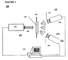
- FIG. 1 shows schematically a temperature controlled TL system 100 of the invention.
- System 100 comprises at least one TLD element 102, which stores energy when exposed to ionizing radiation; a mechanical holder 104 for holding TLD element 102; a heating subsystem 105 (preferably a laser source 106 emitting a laser beam 108 along an optical path to the TLD element) for heating the TLD element; an infrared (IR) radiometry (i.e.
- IR infrared
- thermometer subsystem 110 for monitoring the thermal (IR) radiation emitted from the heated element, thereby determining the temperature of the element; an optical detection subsystem 112 for measuring the (visible or NIR or UV) emitted from the TLD element during heating, and a controlling subsystem (or simply "controller") 114 for using the IR radiation data from subsystem 110 to provide control commands to laser source 106, for plotting the emitted glow curve (emitted intensity I as a function of the temperature T el of the element) and for determining the total dose to which the element had been exposed prior to the TL measurement.
- Subsystem 110 preferably comprises an IR detector 120 in optical communication along an optical path with the TLD element, in front of which there may be placed a filter 122 that transmits IR radiation, but does not transmit UV, visible or NIR radiation.
- Subsystem 112 preferably comprises a photodetector (PD) or a photomultiplier 124 in optical communication along an optical path with the TLD element, in front of which there may be placed a filter 126 that transmits UV, visible and NIR light, but not middle-infrared (mid-IR) radiation. It is understood that the filters may be inserted in the relevant optical paths at various positions, as long as they achieve the required function of transmitting a required radiation and blocking other types of radiation.
- PD photodetector
- mid-IR middle-infrared
- Controller 114 is typically a personal computer running a special program for controlling the heating rate of the TLD element. Other types of controllers capable of control and analysis functions may also be used. Note that while system 100 is shown with the heat source heating only one side of TLD element 102, with the two detectors placed on the opposite side, other configurations are possible and are to be considered within the scope of the present invention. In some embodiments, system 100 may incorporate several TLD elements, which are measured either simultaneously or sequentially. In some embodiments, the functions of IR reading and TL measurements may be combined in one subsystem. While the invention is described in detail with reference to a laser based heating subsystem, it should be clear that many other heating systems and methods, including all those mentioned in the Background may be used for heating the TLD element.
- a TLD element 102 may be made of any material and in any shape mentioned in the Background section and more. In many of the applications it would be desirable to heat the TLD element linearly (or exponentially) at a very rapid rate. Therefore it is desirable that the TLD element has a small mass and be held by a mechanical holder that provides good thermal insulation from the surroundings.
- the TLD element is in the shape of a thin plate or a thin rod.
- mechanical holder 104 comprises one or more holding elements in the form of thin wires, thin springs, or thin needles, to minimize thermal losses to the surroundings. A few exemplary holders 104 are shown in FIG. 2 .
- Figure 2A shows a thin plate TLD element 102 held between four springs 202.
- Figure 2B shows a thin plate TLD element 102 held by four fine wires 204 to a frame 206.
- Figure 2C shows a thin plate TLD element 102 pressed by a thin spring 208 to sharp tipped wires 210. It is to be understood that while identical holding elements may be preferable for uniform heat conduction, non-identical holding elements may be useful in certain applications. The number of "four" is also illustrative: less or more than four holding elements may be used for the purposes set forth herein.
- laser source 106 can be used as laser source 106, including pulsed or CW gas lasers, solid-state lasers or semiconductor lasers.
- TLD elements absorb radiation strongly in the mid-IR range.
- a CO 2 laser with emission at 10.6 ⁇ m may be used for heating most TLD elements, including those deposited on an opaque substrate, or covered with an opaque material.
- a semiconductor laser may be used for heating TLD elements based on powders embedded in a glass that absorbs the radiation emitted by the semiconductor laser.
- the laser beam may impinge directly on the TLD element, may be directed onto the element using standard mirrors or lenses, or may be transmitted via suitable optical fibers that are transparent to the laser wavelength, as described in more detail in a specific example below.
- thermoluminescence results is made much simpler.
- the computer program in PC 114 can continuously increase or decrease the laser power heating the TLD element, so that the temperature varies linearly with time until it reaches some final temperature.
- the laser system discussed above provides very fast monitoring and control, which is not available in other TL systems. This is the result of several factors: (a) IR radiometry provides accurate and very fast measurement of the temperature of the element; (b) the laser power can be changed very rapidly, in response to signals from the computer; (c) the heating of a TLD element by a laser (especially for thin TLD elements) is very fast. This is the reason the system can provide fast heating at a linear rate. It must be stressed that although the heating is fast, the system of this invention controls the temperature and the heating rate during the TL measurement process - something that other systems do not do.
- thermoluminescence emitted by the TLD element (often visible luminescence) upon being heated.
- the emitted TL may be collected and focused on the PD using regular optical elements such as mirrors or lenses. It may also be transmitted from the heated element onto the PD using standard optical fibers, made of silica or polymers.
- the signal from the PD may be amplified and transmitted to the computer for use in the calculation of the glow curve.
- Each TLD system can be calibrated.
- TLD elements are exposed to known doses of radiation, and for each dose a glow curve is measured.
- the computer program can analyze a given glow curve and determine the exact dose to which a TLD element had been exposed.
- the system of the invention is also operative to anneal the TLD elements after a dosimetry measurement, i.e. heat the TLD element to some high temperature (e.g. 400C), or even generate several heating cycles using the laser source.
- the annealing is also fast and well controlled. This annealing eliminates any "memory" effects of a previous exposure. This is important, in order to get accurate results.
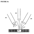
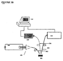
- FIGS. 3A,B shows an embodiment of the system of the present invention based on optical fibers.
- FIG. 3A shows a schematic arrangement of three optical fibers 302, 304 and 306 in optical communication with a TLD element 102.
- FIG. 3B shows the fibers incorporated in a system similar to system 100 of FIG. 1 .
- One fiber is used for heating the TLD element, one for monitoring the temperature of the TLD element, and one for measuring the luminescence emission from the TLD element.
- the laser beam is transmitted through fiber 302.
- Fiber 302 is chosen to transmit efficiently the laser radiation, which may be coupled into the fiber through a couling element (e.g. lens) 150.
- a couling element e.g. lens
- Fiber 304 is an IR fiber that transmits the thermal IR radiation emitted from the TLD element to IR detector 120, and may optionally serve as a filter that blocks UV, visible and NIR radiation from the IR detector.
- Fiber 306 transmits the TL emission from the TLD element to PD 124.
- This fiber is normally made of silica based glass or on some polymer transparent to visible light, and may optionally also serve as a filter, which transmits only UV, visible and NIR radiation, but blocks the thermal (mid ⁇ IR) radiation to the PD.
- PC 114 fulfills the same functions as described with reference to FIG. 1 .
- the arrangement (e.g. bundle) of three fibers, shown in FIGS. 3A , B, may also be used for TL measurement in a remote location.
- a fiber based-TLD measurement systems of the present invention may be based on less or more than 3 fibers, with one or more fibers implementing more than one function.
- the system of the present invention may be used in applications that require more than one TLD element.
- badges worn by personnel in the vicinity of a radiation source may include several TLD elements.
- FIG. 4 shows schematically (A) in cross section and (B) in plane view a badge with four TLD elements.
- the badge comprises a card 402 with four openings 404, each opening housing a thin TLD element 102 held by four thin wires 406.
- the card is inserted into a cassette 408, which is worn as a badge, and (if needed) the card can be pulled out for the TL measurement.
- each or only some of the TLD elements in the badge may be measured by the system, using for example the 3 - fiber arrangement of FIG. 3 .
- One may, for example, measure two of the elements, in order to get more accurate results, and leave two elements untouched for future reference
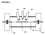
- FIG. 5 is a schematic drawing of a measurement setup for a TLD element heated under vacuum, using the scheme of FIG. 3 .
- Card 402 may be inserted in a vacuum chamber 502 shown schematically in Figure 5 .
- the TL measurements may also be done using standard optical elements such as mirrors, lenses, or windows, but it is much preferable to use optical fibers in this case.
- the bundle of three fibers may be inserted into the vacuum chamber, through suitable ports, and the whole TL measurement can be carried out under vacuum. More than one TLD element may be measured, as discussed with reference to FIG. 4 .
- FIG. 6 illustrates an alternative embodiment of the TLD system of the present invention for in vivo radiation monitoring of radiation doses in a patient undergoing radiation therapy.
- the effectiveness of radiation treatment can be improved by monitoring radiation doses in patients undergoing radiation therapy.
- a radiation dosimeter if operated in real time, can help the physician determined what dose was applied to this portion of the body during irradiation.
- FIG. 6A shows a TLD system 602 having three fibers (exemplarily the fibers described in FIG. 3 ) 604, 606 and 608 inserted inside a hypodermic needle or a catheter 610.
- FIG. 6B shows one infrared fiber 620, which transmits the laser beam to the TLD element and also transmits the thermal infrared radiation from the TLD element to the IR detector.
- An array of visible fibers 622 transmits the TL from the heated TLD element to the photodetector.
- Figure 6C shows one fiber 630 for transmitting the laser beam onto the TLD element and another fiber 632 for transmitting the thermal IR radiation from the TLD element to the infrared detector.
- Two other fibers 634 transmit the thermoluminescence from the heated TLD element to the photodetector.
- the needle may be inserted, for example, into a tumor, and the TLD element in the needle exposed to radiation.
- the laser controlled TLD system will operate much the same way as discussed earlier. This will provide the physician with the radiation dose.
- the TLD element(s) can be used again.
- the physician can decide, at this stage, whether to stop the radiation or to continue with the therapy.
- a second, third, or more doses can be read in real time if needed. Further, if needed, the system can also perform the annealing step between consecutive dose measurements.
- the system of the present invention thus allows precise control of radiation doses, reduces the damage to healthy tissues, and increases the effectiveness of the therapeutic method.
- a larger tube may replace the needle or catheter 610 described above, possibly to carry out radiation dosimetry in any remote location, such as needed for environmental monitoring.
- the tube may be rigid or flexible, and its dimensions and shape may vary.
- the TLD system of FIG. 3B (fiber directed radiation) was used in measurements that illustrate the applicability and performance of the method described herein.
- This mid-IR radiation cannot be transmitted through standard silica based optical fibers, but it can be easily transmitted through silver halide (e.g. AgClBr) fibers.
- the radiation of a CO 2 laser was transmitted through one silver halide fiber to heat a spot on the surface of the TLD element.
- a second silver-halide fiber was used to transmit the thermal IR radiation emitted from the TLD element surface to a liquid nitrogen cooled photonic HgCdTe detector (IR Associates, Stuart, FL, USA), which was part of a fiberoptic infrared radiometer.
- the second fiber also served as a filter that blocked the visible part of the radiation to the IR detector.
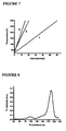
- FIG. 7 shows the time dependence of the temperature of the TLD element for the various heating rates. The figure clearly shows that the temperature dependence is linear for all three heating rates, i.e. the TLD element "temperature control" in achieving a linear heating scheme for each heating rate.
- the present invention advantageously provides a TLD measurement system and method in which the temperature and heating rate of each TLD element is known and controllable in real-time.
- the control is based on real time temperature inputs obtained from IR measurements of the TLD temperature.
- the invention allows therefore to obtain optimized heating rates (i.e. linear) that ensure acquisition of more reproducible and accurate dosimetry results than known in prior art.
Landscapes
- Physics & Mathematics (AREA)
- Health & Medical Sciences (AREA)
- Life Sciences & Earth Sciences (AREA)
- General Physics & Mathematics (AREA)
- High Energy & Nuclear Physics (AREA)
- Molecular Biology (AREA)
- Spectroscopy & Molecular Physics (AREA)
- Photometry And Measurement Of Optical Pulse Characteristics (AREA)
Claims (18)
- Dosismessungssystem (100) auf der Basis von Thermolumineszenz,
welches mindestens ein thermolumineszierendes Dosismessungs (TLD)-Element (102) umfasst, das so funktioniert, dass es kontrollierbar erwärmt wird und während der Erwärmung Lumineszenz emittiert, wobei die emittierte Lumineszenz mit einer Strahlungsdosis in Wechselbeziehung steht, der das TLD-Element ausgesetzt wurde, und das System dadurch gekennzeichnet ist, dass es ferner umfasst:ein Infrarot (IR)-Radiometriesubsystem (110) zum Überwachen der Wärmestrahlung, die von jedem TLD-Element während der Erwärmung emittiert wird, und zum Bereitstellen jeweiliger Wärmestrahlungseingaben, die bei der kontrollierbaren Erwärmung verwendet werden, wobei die Wärmestrahlung einen Temperaturwert des TLD-Elements anzeigt. - System nach Anspruch 1, ferner umfassend:ein Heizsubsystem (105) zum Bereitstellen der kontrollierbaren Erwärmung jedes TLD-Elements;ein Thermolumineszenz (TL)-Messsubsystem (112) zum Messen der emittierten Lumineszenz und zum Bereitstellen von Lumineszenzdaten; undein Steuerungssubsystem (114) zum Steuern von Heizparametern des Heizsubsystems als Antwort auf die IR-Strahlungseingaben und zum Bereitstellen mindestens einer Glühkurve basierend auf den Lumineszenzdaten, wobei die Glühkurve die Strahlungsdosis anzeigt.
- TLD-System nach Anspruch 1, wobei das IR-Radiometriesubsystem mindestens einen IR-Detektor (120) umfasst.
- TLD-System nach Anspruch 3, wobei der mindestens eine IR-Detektor aus der Gruppe bestehend aus einem thermischen Detektor und einem photonischen Detektor ausgewählt ist.
- TLD-System nach Anspruch 2, wobei das Heizsubsystem einen Laser (106) mit einem Laserstrahl (108) umfasst.
- TLD-System nach Anspruch 5, wobei das Heizsubsystem ferner mindestens eine optische Faser umfasst, die mit dem Laser gekoppelt ist und so funktioniert, dass sie den Laserstrahl an jedes TLD-Element (302) überträgt.
- TLD-System nach Anspruch 3, wobei das IR-Radiometriesubsystem ferner eine IRdurchlässige optische Faser (304) zum Koppeln des IR-Detektors mit jedem TLD-Element entlang eines Strahlengangs umfasst.
- TLD-System nach Anspruch 7, wobei das IR-Radiometriesubsystem ferner ein Filter (122) umfasst, dass thermische Strahlung durchlässt, aber NIR-, sichtbare und UV-Strahlung blockiert, wobei das Filter in den Strahlengang eingefügt ist.
- TLD-System nach Anspruch 8, wobei das TL-Messsubsystem eine optische Faser (306) umfasst, die für die Lumineszenz durchlässig ist und mit dem TLD-Element entlang eines Strahlengangs und einem Filter (126) gekoppelt ist, das für die Lumineszenz durchlässig und für Wärmestrahlung undurchlässig ist, wobei das Filter in den Strahlengang eingefügt ist.
- TLD-System nach Anspruch 2, wobei jedes der Heiz-, IR-Radiometrie- und TL-Messsubsysteme mindestens eine jeweilige optische Faser (604, 606, 608) zum Koppeln einer jeweiligen Strahlung in das mindestens eine oder aus dem mindestens einen TLD-Element entlang des jeweiligen Strahlengangs umfasst.
- TLD-System nach Anspruch 10, wobei alle jeweiligen optischen Fasern in einem Gehäuse (610) gebündelt sind, das aus der Gruppe ausgewählt ist, die aus einer hypodermischen Nadel, einem Katheter und einer Röhre besteht.
- TLD-System nach Anspruch 5, wobei der Laser aus der Gruppe bestehend aus einem Impulslaser, einem Dauerstrichlaser, einem Festkörperlaser und einem Halbleiterlaser ausgewählt ist.
- Verfahren zur Durchführung einer Dosismessung auf der Basis von Thermolumineszenz (TL) unter Verwendung eines Thermolumineszenz-Dosismessungs (TLD)-Elements (102), das einer unbekannten Strahlungsdosis ausgesetzt wird, umfassend die folgenden Schritte:Erwärmen des TLD-Elements bei einer kontrollierte Rate auf der Basis von Echtzeit-Temperatureingaben, die durch Überwachen der Wärmestrahlung, die vom TLD-Element während der Erwärmung emittiert wird, unter Verwendung eines Infrarot (IR)- Radiometriesubsystems erhalten werden;Durchführen von TL-Messungen am erwärmten TLD-Element, um eine Glühkurve zu erhalten;Analysieren der Glühkurve, um die Strahlungsdosis zu bestimmen, der das TLD-Element ausgesetzt wurde.
- Verfahren nach Anspruch 13, wobei dem Schritt des Aussetzens ein Schritt des Glühens des TLD-Elements bei einer hohen Temperatur vorangeht, um jegliche Erinnerung an frühere Messungen zu löschen,
- Verfahren nach Anspruch 13, wobei der Schritt des Erwärmens eines TLD-Elements bei einer kontrollierten Rate das Erhalten von Infrarot (IR)-Temperaturmesswerten vom TLD-Element umfasst, wobei die IR-Messweite als die Echtzeit-Temperatureingaben dienen.
- Verfahren nach Anspruch 13, wobei der Schritt des Erwärmens das Verwenden eines Lasers umfasst
- Verfahren nach Anspruch 16, wobei das Erwärmen unter Verwendung eines Lasers, der Schritt des Durchführens von TL-Messungen und das Erhalten von IR-Temperaturmesswerten das Verwenden von jeweiligen optischen Fasern umfassen, um Laserstrahlung, TL-Emissionsstrahlung bzw. IR-Strahlung zu übertragen, um dadurch eine Femdosismessung auf TL-Basis zu ermöglichen.
- Verfahren nach Anspruch 16, wobei das Verwenden von jeweiligen optischen Fasern das Bündeln der optischen Fasern (604, 606, 608) in einem Gehäuse (610) umfasst.
Applications Claiming Priority (1)
| Application Number | Priority Date | Filing Date | Title |
|---|---|---|---|
| US60641904P | 2004-09-02 | 2004-09-02 |
Publications (2)
| Publication Number | Publication Date |
|---|---|
| EP1632792A1 EP1632792A1 (de) | 2006-03-08 |
| EP1632792B1 true EP1632792B1 (de) | 2012-05-30 |
Family
ID=35241211
Family Applications (1)
| Application Number | Title | Priority Date | Filing Date |
|---|---|---|---|
| EP05019007A Expired - Lifetime EP1632792B1 (de) | 2004-09-02 | 2005-09-01 | Thermolumineszenzmessungen und Dosimetrie mit Temperaturkontrolle des Thermolunineszenzelements |
Country Status (2)
| Country | Link |
|---|---|
| US (1) | US7439524B2 (de) |
| EP (1) | EP1632792B1 (de) |
Families Citing this family (19)
| Publication number | Priority date | Publication date | Assignee | Title |
|---|---|---|---|---|
| US7425705B2 (en) * | 2004-12-20 | 2008-09-16 | The United States Of America As Represented By The Secretary Of The Army | Thermoluminescent reader system |
| US7920071B2 (en) * | 2006-05-26 | 2011-04-05 | Itt Manufacturing Enterprises, Inc. | Augmented reality-based system and method providing status and control of unmanned vehicles |
| US9323055B2 (en) * | 2006-05-26 | 2016-04-26 | Exelis, Inc. | System and method to display maintenance and operational instructions of an apparatus using augmented reality |
| US20080218331A1 (en) * | 2007-03-08 | 2008-09-11 | Itt Manufacturing Enterprises, Inc. | Augmented reality-based system and method to show the location of personnel and sensors inside occluded structures and provide increased situation awareness |
| KR101251591B1 (ko) * | 2009-09-21 | 2013-04-08 | 가톨릭대학교 산학협력단 | 개별적으로 확장되는 벌룬을 구비하는 자궁 강 내 조사용 기구 및 시스템 |
| US8541761B2 (en) | 2010-01-12 | 2013-09-24 | Landauer, Inc. | Portable dosimeter |
| RU2482512C2 (ru) * | 2010-03-29 | 2013-05-20 | Федеральное государственное казенное военное образовательное учреждение высшего профессионального образования "Военная академия войск радиационной, химической и биологической защиты и инженерных войск имени Маршала Советского Союза С.К. Тимошенко" Министерства обороны Российской Федерации | Войсковой многофункциональный унифицированный комплекс из трех моноблочных устройств для дозиметрического контроля |
| EP2556390A4 (de) | 2010-04-09 | 2014-10-29 | Landauer Inc | Stromsystem für ein dosimeter-lesegerät |
| CA2803827C (en) | 2010-07-07 | 2014-04-08 | University Health Network | Fiber optic radiochromic dosimeter probe and method to make the same |
| RU2486545C1 (ru) * | 2011-12-21 | 2013-06-27 | Открытое акционерное общество "Специализированный научно-исследовательский институт приборостроения" (ОАО "СНИИП") | Термолюминесцентный дозиметрический считыватель |
| US9268030B2 (en) * | 2013-03-05 | 2016-02-23 | The United States Of America, As Represented By The Secretary Of The Navy | Laser-heated thermoluminescence dosimeter |
| RU2526235C1 (ru) * | 2013-04-05 | 2014-08-20 | Федеральное государственное автономное образовательное учреждение высшего профессионального образования "Уральский федеральный университет имени первого Президента России Б.Н. Ельцина" | Способ термоподготовки к экспозиции термолюминесцентного детектора ионизирующих излучений на основе оксида алюминия |
| RU2532506C1 (ru) * | 2013-07-31 | 2014-11-10 | Федеральное государственное автономное образовательное учреждение высшего профессионального образования "Уральский федеральный университет имени первого Президента России Б.Н. Ельцина" | Способ термолучевой обработки вещества тл-осл твердотельного детектора ионизирующих излучений на основе оксида алюминия |
| GB2522240A (en) * | 2014-01-19 | 2015-07-22 | Dosevue Nv | Minimally invasive applicator for in-situ radiation dosimetry |
| GB2523178A (en) * | 2014-02-18 | 2015-08-19 | Dosevue Nv | Locally injectable dosimetric organ spacer |
| CN105068105B (zh) * | 2015-08-18 | 2017-09-26 | 浙江建安检测研究院有限公司 | 加速器机头泄漏辐射测试方法 |
| US10488275B2 (en) * | 2015-12-16 | 2019-11-26 | The United States Of America As Represented By The Secretary Of The Navy | Device for noninvasively verifying thermoluminescent dosimeter card heater time temperature profile |
| JP2017187405A (ja) * | 2016-04-06 | 2017-10-12 | 富士電機株式会社 | 粒子成分分析装置、粒子複合分析装置および粒子成分分析装置の使用方法 |
| CN107884803B (zh) * | 2017-11-29 | 2024-03-19 | 中核控制系统工程有限公司 | 一种热释光照射器 |
Family Cites Families (15)
| Publication number | Priority date | Publication date | Assignee | Title |
|---|---|---|---|---|
| DE1514183B2 (de) * | 1965-12-23 | 1972-05-18 | Ernst Leitz Gmbh, 6330 Wetzlar | Verfahren zur auswertung einer lumineszenz-dosimeter-folie mittels infrarit-strahlung |
| US3729630A (en) * | 1970-02-05 | 1973-04-24 | Matsushita Electric Industrial Co Ltd | Thermoluminescence readout instrument |
| US3809901A (en) * | 1971-11-30 | 1974-05-07 | Kewanee Oil Co | Automatic thermoluminescence dosimetric system with coded card |
| US3790784A (en) * | 1972-06-06 | 1974-02-05 | Isotopes Inc | Method and apparatus for treating thermoluminescent dosimeters during read-out to enable their immediate reuse |
| US3975637A (en) * | 1973-10-23 | 1976-08-17 | Matsushita Electric Industrial Co., Ltd. | Device for storage and display of a radiation image |
| DE2742556A1 (de) * | 1976-09-22 | 1978-03-23 | Matsushita Electric Ind Co Ltd | Verfahren zum ablesen eines thermolumineszenten dosimeters |
| US4638163A (en) * | 1984-09-20 | 1987-01-20 | Peter F. Braunlich | Method and apparatus for reading thermoluminescent phosphors |
| US5041734A (en) * | 1984-09-20 | 1991-08-20 | International Sensor Technology, Inc. | Dosimeter reading apparatus with optical laser converter |
| US4906848A (en) * | 1984-09-20 | 1990-03-06 | International Sensor Technology, Inc. | Apparatuses and methods for laser reading of phosphors |
| US5081363A (en) * | 1984-09-20 | 1992-01-14 | International Sensor Technology, Inc. | Dosimeter reading apparatus with optical laser converter |
| US4835388A (en) * | 1987-04-07 | 1989-05-30 | The Harshaw Chemical Company | Thermoluminescence dosimetry card reader heating assembly |
| US5606163A (en) * | 1995-01-11 | 1997-02-25 | The United States Of America As Represented By The Secretary Of The Navy | All-optical, rapid readout, fiber-coupled thermoluminescent dosimeter system |
| US6414324B1 (en) * | 1998-05-13 | 2002-07-02 | The Board Of Regents For Oklahoma State University | Method of preparing detection materials for use in UV detection using phototransferred thermoluminescence |
| US6005231A (en) * | 1998-05-29 | 1999-12-21 | Matsushita Industrial Equipment Corp. Of America | Method for determining the temperature of a thermoluminescence element being heated for thermoluminescence dosimetry |
| US7537381B2 (en) * | 2003-12-02 | 2009-05-26 | White Box, Inc. | Measurement system and method |
-
2005
- 2005-08-31 US US11/214,735 patent/US7439524B2/en active Active
- 2005-09-01 EP EP05019007A patent/EP1632792B1/de not_active Expired - Lifetime
Also Published As
| Publication number | Publication date |
|---|---|
| US20060043314A1 (en) | 2006-03-02 |
| EP1632792A1 (de) | 2006-03-08 |
| US7439524B2 (en) | 2008-10-21 |
Similar Documents
| Publication | Publication Date | Title |
|---|---|---|
| EP1632792B1 (de) | Thermolumineszenzmessungen und Dosimetrie mit Temperaturkontrolle des Thermolunineszenzelements | |
| Bøtter-Jensen et al. | Al2O3: C as a sensitive OSL dosemeter for rapid assessment of environmental photon dose rates | |
| US4999504A (en) | Remote radiation dosimetry | |
| EP0178703B1 (de) | Verfahren und Vorrichtung zum Ablesen von Thermolumineszenzphosphor | |
| Huston et al. | Remote optical fiber dosimetry | |
| Bøtter-Jensen et al. | Advances in luminescence instrument systems | |
| US8711342B2 (en) | Photoacoustic joulemeter utilizing beam deflection technique | |
| Okada et al. | TSL/OSL/RPL Automated and Integrated Measurement System (TORAIMS). | |
| McKeever et al. | Build-up of radiophotoluminescence (RPL) in Ag-doped phosphate glass in real-time both during and after exposure to ionizing radiation: A proposed model | |
| KR20210098474A (ko) | 방사선 구동식 고 선량률 및 고 선량 방사선 센서 | |
| US9121948B2 (en) | Optically stimulated luminescence dosimetry using doped lithium fluoride crystals | |
| L. Huston et al. | Optically stimulated luminescent glass optical fibre dosemeter | |
| Bøtter-Jensen et al. | Enhancements in luminescence measurement techniques | |
| WO2010017218A2 (en) | Method and apparatus to discriminate out interference in radiation dosage measurements | |
| Bøtter-Jensen et al. | Optically stimulated luminescence techniques in retrospective dosimetry | |
| França et al. | Development of a thermoluminescence and radioluminescence integrated spectrometer | |
| Braunlich | Present state and future of TLD laser heating | |
| US6005231A (en) | Method for determining the temperature of a thermoluminescence element being heated for thermoluminescence dosimetry | |
| Nunes et al. | A custom-made integrated system for thermoluminescence and radioluminescence spectroscopy | |
| Bøtter-Jensen et al. | Application of luminescence techniques in retrospective dosimetry | |
| Sporea | Optical fiber sensors in ionizing radiation environments | |
| Sobotka et al. | Efficient reading of thermoluminescent dosimeter signals using semiconductor detectors | |
| Correia et al. | A multi-sensor dosimeter for brachytherapy based on radioluminescent fiber sensors | |
| Rahman et al. | OSL using a prototype fibre-mounted sensor and automated reader assembly | |
| US3582652A (en) | Method for reading a thermoluminescent dosimeter |
Legal Events
| Date | Code | Title | Description |
|---|---|---|---|
| PUAI | Public reference made under article 153(3) epc to a published international application that has entered the european phase |
Free format text: ORIGINAL CODE: 0009012 |
|
| AK | Designated contracting states |
Kind code of ref document: A1 Designated state(s): AT BE BG CH CY CZ DE DK EE ES FI FR GB GR HU IE IS IT LI LT LU LV MC NL PL PT RO SE SI SK TR |
|
| AX | Request for extension of the european patent |
Extension state: AL BA HR MK YU |
|
| 17P | Request for examination filed |
Effective date: 20060717 |
|
| 17Q | First examination report despatched |
Effective date: 20060811 |
|
| AKX | Designation fees paid |
Designated state(s): AT BE BG CH CY CZ DE DK EE ES FI FR GB GR HU IE IS IT LI LT LU LV MC NL PL PT RO SE SI SK TR |
|
| RAP1 | Party data changed (applicant data changed or rights of an application transferred) |
Owner name: KATZIR, ABRAHAM |
|
| RIN1 | Information on inventor provided before grant (corrected) |
Inventor name: GAYER, OFER Inventor name: KATZIR, ABRAHAM |
|
| REG | Reference to a national code |
Ref country code: DE Ref legal event code: R079 Ref document number: 602005034384 Country of ref document: DE Free format text: PREVIOUS MAIN CLASS: G01T0001115000 Ipc: G01T0001110000 |
|
| GRAP | Despatch of communication of intention to grant a patent |
Free format text: ORIGINAL CODE: EPIDOSNIGR1 |
|
| RIC1 | Information provided on ipc code assigned before grant |
Ipc: G01T 1/11 20060101AFI20111108BHEP Ipc: G01T 1/115 20060101ALI20111108BHEP |
|
| GRAS | Grant fee paid |
Free format text: ORIGINAL CODE: EPIDOSNIGR3 |
|
| GRAA | (expected) grant |
Free format text: ORIGINAL CODE: 0009210 |
|
| AK | Designated contracting states |
Kind code of ref document: B1 Designated state(s): AT BE BG CH CY CZ DE DK EE ES FI FR GB GR HU IE IS IT LI LT LU LV MC NL PL PT RO SE SI SK TR |
|
| REG | Reference to a national code |
Ref country code: GB Ref legal event code: FG4D |
|
| REG | Reference to a national code |
Ref country code: CH Ref legal event code: EP |
|
| REG | Reference to a national code |
Ref country code: AT Ref legal event code: REF Ref document number: 560311 Country of ref document: AT Kind code of ref document: T Effective date: 20120615 |
|
| REG | Reference to a national code |
Ref country code: IE Ref legal event code: FG4D |
|
| REG | Reference to a national code |
Ref country code: DE Ref legal event code: R096 Ref document number: 602005034384 Country of ref document: DE Effective date: 20120802 |
|
| REG | Reference to a national code |
Ref country code: NL Ref legal event code: VDEP Effective date: 20120530 |
|
| REG | Reference to a national code |
Ref country code: LT Ref legal event code: MG4D Effective date: 20120530 |
|
| PG25 | Lapsed in a contracting state [announced via postgrant information from national office to epo] |
Ref country code: SE Free format text: LAPSE BECAUSE OF FAILURE TO SUBMIT A TRANSLATION OF THE DESCRIPTION OR TO PAY THE FEE WITHIN THE PRESCRIBED TIME-LIMIT Effective date: 20120530 Ref country code: FI Free format text: LAPSE BECAUSE OF FAILURE TO SUBMIT A TRANSLATION OF THE DESCRIPTION OR TO PAY THE FEE WITHIN THE PRESCRIBED TIME-LIMIT Effective date: 20120530 Ref country code: CY Free format text: LAPSE BECAUSE OF FAILURE TO SUBMIT A TRANSLATION OF THE DESCRIPTION OR TO PAY THE FEE WITHIN THE PRESCRIBED TIME-LIMIT Effective date: 20120530 Ref country code: IS Free format text: LAPSE BECAUSE OF FAILURE TO SUBMIT A TRANSLATION OF THE DESCRIPTION OR TO PAY THE FEE WITHIN THE PRESCRIBED TIME-LIMIT Effective date: 20120930 Ref country code: LT Free format text: LAPSE BECAUSE OF FAILURE TO SUBMIT A TRANSLATION OF THE DESCRIPTION OR TO PAY THE FEE WITHIN THE PRESCRIBED TIME-LIMIT Effective date: 20120530 |
|
| REG | Reference to a national code |
Ref country code: AT Ref legal event code: MK05 Ref document number: 560311 Country of ref document: AT Kind code of ref document: T Effective date: 20120530 |
|
| PG25 | Lapsed in a contracting state [announced via postgrant information from national office to epo] |
Ref country code: SI Free format text: LAPSE BECAUSE OF FAILURE TO SUBMIT A TRANSLATION OF THE DESCRIPTION OR TO PAY THE FEE WITHIN THE PRESCRIBED TIME-LIMIT Effective date: 20120530 Ref country code: LV Free format text: LAPSE BECAUSE OF FAILURE TO SUBMIT A TRANSLATION OF THE DESCRIPTION OR TO PAY THE FEE WITHIN THE PRESCRIBED TIME-LIMIT Effective date: 20120530 Ref country code: GR Free format text: LAPSE BECAUSE OF FAILURE TO SUBMIT A TRANSLATION OF THE DESCRIPTION OR TO PAY THE FEE WITHIN THE PRESCRIBED TIME-LIMIT Effective date: 20120831 |
|
| PG25 | Lapsed in a contracting state [announced via postgrant information from national office to epo] |
Ref country code: BE Free format text: LAPSE BECAUSE OF FAILURE TO SUBMIT A TRANSLATION OF THE DESCRIPTION OR TO PAY THE FEE WITHIN THE PRESCRIBED TIME-LIMIT Effective date: 20120530 |
|
| PG25 | Lapsed in a contracting state [announced via postgrant information from national office to epo] |
Ref country code: AT Free format text: LAPSE BECAUSE OF FAILURE TO SUBMIT A TRANSLATION OF THE DESCRIPTION OR TO PAY THE FEE WITHIN THE PRESCRIBED TIME-LIMIT Effective date: 20120530 Ref country code: DK Free format text: LAPSE BECAUSE OF FAILURE TO SUBMIT A TRANSLATION OF THE DESCRIPTION OR TO PAY THE FEE WITHIN THE PRESCRIBED TIME-LIMIT Effective date: 20120530 Ref country code: EE Free format text: LAPSE BECAUSE OF FAILURE TO SUBMIT A TRANSLATION OF THE DESCRIPTION OR TO PAY THE FEE WITHIN THE PRESCRIBED TIME-LIMIT Effective date: 20120530 Ref country code: CZ Free format text: LAPSE BECAUSE OF FAILURE TO SUBMIT A TRANSLATION OF THE DESCRIPTION OR TO PAY THE FEE WITHIN THE PRESCRIBED TIME-LIMIT Effective date: 20120530 Ref country code: RO Free format text: LAPSE BECAUSE OF FAILURE TO SUBMIT A TRANSLATION OF THE DESCRIPTION OR TO PAY THE FEE WITHIN THE PRESCRIBED TIME-LIMIT Effective date: 20120530 Ref country code: NL Free format text: LAPSE BECAUSE OF FAILURE TO SUBMIT A TRANSLATION OF THE DESCRIPTION OR TO PAY THE FEE WITHIN THE PRESCRIBED TIME-LIMIT Effective date: 20120530 Ref country code: SK Free format text: LAPSE BECAUSE OF FAILURE TO SUBMIT A TRANSLATION OF THE DESCRIPTION OR TO PAY THE FEE WITHIN THE PRESCRIBED TIME-LIMIT Effective date: 20120530 |
|
| PG25 | Lapsed in a contracting state [announced via postgrant information from national office to epo] |
Ref country code: IT Free format text: LAPSE BECAUSE OF FAILURE TO SUBMIT A TRANSLATION OF THE DESCRIPTION OR TO PAY THE FEE WITHIN THE PRESCRIBED TIME-LIMIT Effective date: 20120530 Ref country code: PT Free format text: LAPSE BECAUSE OF FAILURE TO SUBMIT A TRANSLATION OF THE DESCRIPTION OR TO PAY THE FEE WITHIN THE PRESCRIBED TIME-LIMIT Effective date: 20121001 Ref country code: PL Free format text: LAPSE BECAUSE OF FAILURE TO SUBMIT A TRANSLATION OF THE DESCRIPTION OR TO PAY THE FEE WITHIN THE PRESCRIBED TIME-LIMIT Effective date: 20120530 |
|
| PLBE | No opposition filed within time limit |
Free format text: ORIGINAL CODE: 0009261 |
|
| STAA | Information on the status of an ep patent application or granted ep patent |
Free format text: STATUS: NO OPPOSITION FILED WITHIN TIME LIMIT |
|
| PG25 | Lapsed in a contracting state [announced via postgrant information from national office to epo] |
Ref country code: ES Free format text: LAPSE BECAUSE OF FAILURE TO SUBMIT A TRANSLATION OF THE DESCRIPTION OR TO PAY THE FEE WITHIN THE PRESCRIBED TIME-LIMIT Effective date: 20120910 Ref country code: MC Free format text: LAPSE BECAUSE OF NON-PAYMENT OF DUE FEES Effective date: 20120930 |
|
| REG | Reference to a national code |
Ref country code: CH Ref legal event code: PL |
|
| 26N | No opposition filed |
Effective date: 20130301 |
|
| REG | Reference to a national code |
Ref country code: IE Ref legal event code: MM4A |
|
| REG | Reference to a national code |
Ref country code: DE Ref legal event code: R097 Ref document number: 602005034384 Country of ref document: DE Effective date: 20130301 |
|
| PG25 | Lapsed in a contracting state [announced via postgrant information from national office to epo] |
Ref country code: LI Free format text: LAPSE BECAUSE OF NON-PAYMENT OF DUE FEES Effective date: 20120930 Ref country code: CH Free format text: LAPSE BECAUSE OF NON-PAYMENT OF DUE FEES Effective date: 20120930 Ref country code: BG Free format text: LAPSE BECAUSE OF FAILURE TO SUBMIT A TRANSLATION OF THE DESCRIPTION OR TO PAY THE FEE WITHIN THE PRESCRIBED TIME-LIMIT Effective date: 20120830 Ref country code: IE Free format text: LAPSE BECAUSE OF NON-PAYMENT OF DUE FEES Effective date: 20120901 |
|
| PG25 | Lapsed in a contracting state [announced via postgrant information from national office to epo] |
Ref country code: TR Free format text: LAPSE BECAUSE OF FAILURE TO SUBMIT A TRANSLATION OF THE DESCRIPTION OR TO PAY THE FEE WITHIN THE PRESCRIBED TIME-LIMIT Effective date: 20120530 |
|
| PG25 | Lapsed in a contracting state [announced via postgrant information from national office to epo] |
Ref country code: LU Free format text: LAPSE BECAUSE OF NON-PAYMENT OF DUE FEES Effective date: 20120901 |
|
| PG25 | Lapsed in a contracting state [announced via postgrant information from national office to epo] |
Ref country code: HU Free format text: LAPSE BECAUSE OF FAILURE TO SUBMIT A TRANSLATION OF THE DESCRIPTION OR TO PAY THE FEE WITHIN THE PRESCRIBED TIME-LIMIT Effective date: 20050901 |
|
| REG | Reference to a national code |
Ref country code: FR Ref legal event code: PLFP Year of fee payment: 11 |
|
| PGFP | Annual fee paid to national office [announced via postgrant information from national office to epo] |
Ref country code: DE Payment date: 20150924 Year of fee payment: 11 Ref country code: GB Payment date: 20150928 Year of fee payment: 11 |
|
| PGFP | Annual fee paid to national office [announced via postgrant information from national office to epo] |
Ref country code: FR Payment date: 20150930 Year of fee payment: 11 |
|
| REG | Reference to a national code |
Ref country code: DE Ref legal event code: R119 Ref document number: 602005034384 Country of ref document: DE |
|
| GBPC | Gb: european patent ceased through non-payment of renewal fee |
Effective date: 20160901 |
|
| REG | Reference to a national code |
Ref country code: FR Ref legal event code: ST Effective date: 20170531 |
|
| PG25 | Lapsed in a contracting state [announced via postgrant information from national office to epo] |
Ref country code: GB Free format text: LAPSE BECAUSE OF NON-PAYMENT OF DUE FEES Effective date: 20160901 Ref country code: FR Free format text: LAPSE BECAUSE OF NON-PAYMENT OF DUE FEES Effective date: 20160930 Ref country code: DE Free format text: LAPSE BECAUSE OF NON-PAYMENT OF DUE FEES Effective date: 20170401 |