EP1632773A1 - Method of detecting an air bubble in an aqueous liquid - Google Patents
Method of detecting an air bubble in an aqueous liquid Download PDFInfo
- Publication number
- EP1632773A1 EP1632773A1 EP05450146A EP05450146A EP1632773A1 EP 1632773 A1 EP1632773 A1 EP 1632773A1 EP 05450146 A EP05450146 A EP 05450146A EP 05450146 A EP05450146 A EP 05450146A EP 1632773 A1 EP1632773 A1 EP 1632773A1
- Authority
- EP
- European Patent Office
- Prior art keywords
- liquid
- sensor
- gas
- bubble
- measuring chamber
- Prior art date
- Legal status (The legal status is an assumption and is not a legal conclusion. Google has not performed a legal analysis and makes no representation as to the accuracy of the status listed.)
- Granted
Links
Images
Classifications
-
- G—PHYSICS
- G01—MEASURING; TESTING
- G01N—INVESTIGATING OR ANALYSING MATERIALS BY DETERMINING THEIR CHEMICAL OR PHYSICAL PROPERTIES
- G01N27/00—Investigating or analysing materials by the use of electric, electrochemical, or magnetic means
- G01N27/26—Investigating or analysing materials by the use of electric, electrochemical, or magnetic means by investigating electrochemical variables; by using electrolysis or electrophoresis
- G01N27/403—Cells and electrode assemblies
- G01N27/404—Cells with anode, cathode and cell electrolyte on the same side of a permeable membrane which separates them from the sample fluid, e.g. Clark-type oxygen sensors
-
- G—PHYSICS
- G01—MEASURING; TESTING
- G01N—INVESTIGATING OR ANALYSING MATERIALS BY DETERMINING THEIR CHEMICAL OR PHYSICAL PROPERTIES
- G01N27/00—Investigating or analysing materials by the use of electric, electrochemical, or magnetic means
- G01N27/26—Investigating or analysing materials by the use of electric, electrochemical, or magnetic means by investigating electrochemical variables; by using electrolysis or electrophoresis
- G01N27/416—Systems
- G01N27/4163—Systems checking the operation of, or calibrating, the measuring apparatus
Definitions
- the invention relates to a method for detecting a gas bubble, preferably an air bubble, in an aqueous liquid, preferably a calibration, control or sample liquid, which gas bubble is in at least partial contact with the sensitive region of a arranged in a measuring chamber, amperometric sensor for determining the concentration of a dissolved in the liquid gas component is located.
- analysis systems are used for blood gas analysis or other measurements on samples in liquid form. Such systems are used, for example, to determine the oxygen or carbon dioxide partial pressure of blood, the hemoglobin parameter of whole blood, and the pH or concentration of ions or specific metabolites.
- Such complex analysis systems often have different sensory elements for determining the respective parameters, which are used for many determinations.
- Such sensory elements are, for example, electrochemical or optical sensors for determining the gas values, the pH, the ion values and the metabolite values or optical measuring units for determining the hemoglobin values.
- US 3,874,850 A (Sorensen et al.) Describes such an analysis system for blood analysis.
- This system has several sensory elements used to determine the pH, partial pressures of oxygen and carbon dioxide, and the hemoglobin content of a blood sample.
- These sensory elements are connected by a complex fluidic system of various fluidic components such as hoses, storage and waste containers, pumps or valves, in which system the sample is transported from the patient to the analysis system by means of syringes or capillaries.
- this inner electrolyte space also contains electrodes for the electrochemical determination of the gas, in particular measuring or working electrodes, counterelectrodes or reference electrodes.
- the actual electrochemical detection reactions for the determination of the gas proceed by means of amperometric methods.
- a frequently used gas sensor is for example the oxygen sensor according to Clark.
- a gas-permeable membrane separates the inner electrolyte solution from the aqueous outer medium, the measuring medium.
- two electrodes are immersed in the inner electrolyte solution, one of which is arranged as a working electrode close behind the membrane.
- the oxygen diffused from the measuring medium through the membrane into the inner electrolyte space is consumed at the working electrode by electrochemical reduction, and a current corresponding to the substance conversion flows. This current is proportional to the oxygen partial pressure in the measuring medium and represents the primary measured variable.
- electrochemical gas sensors which possess such gas-permeable membranes are, for example, electrochemical sensors for the determination of hydrogen by means of oxidation on platinum electrodes.
- Such electrochemical gas sensors are often used in medical and diagnostic analysis systems for determining gas partial pressures or gas concentrations in liquids.
- electrochemical gas sensors are used in blood gas analyzers, which play a major role in diagnostics.
- Blood gas analyzers often had several sensors connected in series for different parameters.
- the sample liquid flows through the measuring channel of a measuring chamber, which contains these sensors, whereby the measurement often takes place in the so-called "stop-flow method" with the sample resting at the time of the measurement.
- stop-flow method Such systems are often used in routine operations in hospitals, laboratories and practices, so that the sensors contained therein make high demands in terms of service life, accuracy and reproducibility.
- amperometric oxygen sensors are used to determine oxygen in the OMNI analysis systems of Roche Diagnostics GmbH.
- the oxygen sensors are miniaturized gas sensors of the Clark type.
- These gas sensor elements used there comprise, in addition to the actual sensor with inner electrolyte space and the electrodes therein, a sample channel for transporting and providing the sample.
- a gas-permeable and largely ion- and liquid-impermeable plastic membrane which separates the inner electrolyte space and the sample channel.
- the membrane is present here in a mechanically clamped state.
- membranes made of plastics with layer thicknesses in the micrometer range of hydrophobic plastics, in particular polytetrafluoroethylene, polypropylene or polyethylene. Further details on preferred membrane materials are given in "Measurement of Oxygen by Membrane-covered Probes" (Ellis Horwood series of analytical chemistry), 1988, Ellis Horwood Limited, page 91f. to find.
- gas bubbles such as air bubbles
- gas bubbles can lead to erroneous measurements, so that in view of the presence or absence of gas bubbles effective review must be performed.
- Gas bubbles preferably remain hanging on the membrane surface.
- US Pat. No. 4,358,423 A (Nedetzky) already mentions the problem of trapped air bubbles, which falsify the measurement result, since the air bubbles prevent sufficient wetting of the surface of the respectively used sensors. Measures which detect such an error are necessary in particular for automatically operating analyzers in which the filling process of the measuring capillary or the absence of bubbles of the sample in the measuring chamber has to be automatically controlled.
- US Pat. No. 4,358,423 proposes a method for solving the problem, in which the value of the electrical resistance is measured between at least two points in the measuring chamber, the filling process of the measuring chamber being controlled as a function of the detected magnitude of the measured resistance.
- EP 1 394 534 A2 discloses a method and a device for checking the positioning and the absence of bubbles of a medical microsample in a flow measuring cell of an analyzer with the aid of an alternating voltage applied to the measuring cell.
- the measuring cell has a plurality of successively arranged electrode arrangements, each having a plurality of individual electrodes (working, reference and counter electrode) for measuring an ingredient of the microprobe by means of a measuring voltage (essentially a DC voltage).
- both the coupling of the alternating voltage and the coupling of the measuring voltage is carried out directly and simultaneously via the individual electrodes of the respective electrode arrangement and the measured alternating current component or the impedance is a measure of the position the microprobe and its freedom from bubbles.
- Another disadvantage here is that very small air bubbles can not be effectively detected.
- a device for dynamically measuring the bubble content of a flowing liquid having means for measuring the pressure, the temperature and the volumetric flow rate of the liquid, the flow rate being measured between points of high and low pressure and from this, the bubble content of the liquid is calculated.
- the process essentially exploits the change in volume of the liquid resulting from the pressure change, which is dependent on the bubble content.
- WO 01/33195 A1 finally discloses a method and a device for bubble detection in a liquid, in which the liquid is in contact, for example, with a PO 2 sensor.
- a first measured value for the O 2 partial pressure is now carried out at a first pressure value in the measuring chamber, and then the pressure is changed to a second pressure value in the measuring chamber.
- the O 2 partial pressure is measured and a second measured value is created.
- This second measured value is compared with an expected value for the changed pressure and, depending on the difference between the two values, the presence of gas bubbles is concluded.
- Pressure reduction leads to a signal reduction due to the reduction of the O 2 partial pressure of the gas bubble.
- the disadvantage here is the necessity of the exact setting of two pressure values in the measuring chamber.
- the object of the present invention is to improve a method for detecting a gas bubble which is in at least partial contact with the sensitive region of an amperometric sensor arranged in a measuring chamber in such a way that even very small gas bubbles can be produced without additional conversions or installations in the Measuring chamber can be detected clearly, so that appropriate measures can be initiated.
- the inventive method uses the fact mentioned above that amperometric gas sensors consume the analyte. It is assumed that the gas component to be determined by the amperometric sensor is part of the gas bubble to be detected.
- the liquid sensor 2 located in the immediate vicinity of an amperometric O free of O 2 -containing gas bubbles, it is - due to the O 2 consumption of the sensor - during the measurement over time to a depletion of O 2 in In the immediate vicinity of the sensor liquid and thus a decrease in the amperometric signal. You move now the liquid increases in the amperometric signal by a certain amount, which increases in the presence of a gas bubble.
- the second part of the liquid can be moved in front of the sensitive area of the amperometric sensor with a measuring chamber which is open on the inlet and outlet side without any significant pressure change, preferably with the aid of a pumping or suction device.
- a measuring chamber which is open on the inlet and outlet side without any significant pressure change, preferably with the aid of a pumping or suction device.
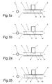
- the measuring arrangement shown schematically in FIGS. 1 a to 2 b has a measuring chamber 1 with a continuous sample channel 2, the inlet opening of which is designated 3.
- a pumping or suction device 6 for example a peristaltic pump.
- a plurality of different, electrochemical sensors may be arranged, but at least one amperometric sensor 7, for example an O 2 sensor whose sensitive area 8 in the sample channel 2 and in the measuring liquid 9 located there (eg calibration, control or sample liquid protrudes.
- the measuring liquid 9 is delimited on the inlet side by a separating gas bubbles 10 from a subsequent liquid sample.
- FIGS. 1 a and 1 b show the measurement situation without a disturbing gas bubble in the sensitive area 8 of the sensor 7, in FIGS. 2 a and 2b with a gas bubble 11 in at least partial contact with the sensitive area 8 of the amperometric sensor 7
- the measuring liquid 9 can be moved from a first position (see Fig. 1a or Fig. 2a) to a second position (see Fig. 1b) without significant pressure changes in the liquid 9, for example by means of the pumping or suction device 6 or Fig. 2b) are shifted so that a second, previously outside the sensitive area of the amperometric Sensor lying, unconsumed part of the liquid 9 in the sensitive region 8 of the amperometric sensor 7 is positioned.
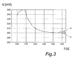
- the amperometric signal is tapped on a current / voltage converter and measured in the form of a voltage proportional to the current.
- the waveform represents the superposition of two different processes: 1) the response of the sensor to the O 2 value of the introduced liquid, wherein the this process conditional waveform decreases until equilibration and 2) the inherent O 2 consumption of the amperometric O 2 sensor, characterized by a steadily decreasing signal over time. A stable signal sets in after approx. 30 s.
- a gas bubble 11 eg air
- the signal decrease due to the O 2 consumption over the time t is essential in comparison to a bubble-free liquid lower.
- the latter is due to the fact that under normal conditions an air bubble contains a significant factor more oxygen than aqueous liquids of the same volume.
- the gas bubble 11 remains in the sensitive area 8 adhere unchanged, wherein the liquid located in the immediate vicinity of the sensor 7 is replaced by new or partially displaced.
- the signal rise remains off (see curve b in FIG. 3).
Landscapes
- Chemical & Material Sciences (AREA)
- Life Sciences & Earth Sciences (AREA)
- Health & Medical Sciences (AREA)
- Biochemistry (AREA)
- Chemical Kinetics & Catalysis (AREA)
- Electrochemistry (AREA)
- Physics & Mathematics (AREA)
- Analytical Chemistry (AREA)
- Molecular Biology (AREA)
- General Health & Medical Sciences (AREA)
- General Physics & Mathematics (AREA)
- Immunology (AREA)
- Pathology (AREA)
- Investigating Or Analysing Biological Materials (AREA)
- Investigating Or Analyzing Materials By The Use Of Electric Means (AREA)
- Sampling And Sample Adjustment (AREA)
Abstract
Description
Die Erfindung betrifft ein Verfahren zur Detektion einer Gasblase, vorzugsweise einer Luftblase, in einer wässrigen Flüssigkeit, vorzugsweise einer Kalibrier-, Kontroll- oder Probenflüssigkeit, welche Gasblase sich in zumindest teilweisem Kontakt mit dem sensitiven Bereich eines in einer Messkammer angeordneten, amperometrischen Sensors zur Bestimmung der Konzentration einer in der Flüssigkeit gelösten Gaskomponente befindet.The invention relates to a method for detecting a gas bubble, preferably an air bubble, in an aqueous liquid, preferably a calibration, control or sample liquid, which gas bubble is in at least partial contact with the sensitive region of a arranged in a measuring chamber, amperometric sensor for determining the concentration of a dissolved in the liquid gas component is located.
In der klinischen Diagnostik werden Analysesysteme zur Blutgasanalyse oder zu sonstigen Messungen an in flüssiger Form vorliegenden Proben verwendet. Solche Systeme werden beispielsweise zur Bestimmung des Sauerstoff- oder Kohlendioxidpartialdrucks von Blut, der Hämoglobinparameter von Vollblut sowie des pH-Werts oder der Konzentration von Ionen oder speziellen Metaboliten eingesetzt.In clinical diagnostics, analysis systems are used for blood gas analysis or other measurements on samples in liquid form. Such systems are used, for example, to determine the oxygen or carbon dioxide partial pressure of blood, the hemoglobin parameter of whole blood, and the pH or concentration of ions or specific metabolites.
Solche komplexen Analysesysteme besitzen zur Bestimmung der jeweiligen Parameter häufig verschiedene sensorische Elemente, welche für viele Bestimmungen eingesetzt werden. Solche sensorischen Elemente sind beispielsweise elektrochemische oder optische Sensoren zur Bestimmung der Gaswerte, des pH-Wertes, der Ionenwerte und der Metabolitwerte oder optische Messeinheiten zur Bestimmung der Hämoglobinwerte.Such complex analysis systems often have different sensory elements for determining the respective parameters, which are used for many determinations. Such sensory elements are, for example, electrochemical or optical sensors for determining the gas values, the pH, the ion values and the metabolite values or optical measuring units for determining the hemoglobin values.
Die US 3,874,850 A (Sorensen et al.) beschreibt ein solches Analysesystem zur Blutanalyse. Dieses System weist mehrere sensorische Elemente auf, welche zur Bestimmung des pH-Wertes, der Partialdrücke von Sauerstoff und Kohlendioxid und des Hämoglobingehaltes einer Blutprobe dienen. Diese sensorischen Elemente sind durch ein komplexes fluidisches System aus verschiedensten fluidischen Bauteilen wie Schläuchen, Vorrats- und Abfallbehältern, Pumpen oder Ventilen verbunden, wobei bei diesem System die Probe mit Hilfe von Spritzen oder Kapillaren vom Patienten zum Analysesystem transportiert wird.US 3,874,850 A (Sorensen et al.) Describes such an analysis system for blood analysis. This system has several sensory elements used to determine the pH, partial pressures of oxygen and carbon dioxide, and the hemoglobin content of a blood sample. These sensory elements are connected by a complex fluidic system of various fluidic components such as hoses, storage and waste containers, pumps or valves, in which system the sample is transported from the patient to the analysis system by means of syringes or capillaries.
Bei elektrochemischen Gassensoren, auch gasselektive oder gassensitive Elektroden genannt, diffundieren die zu bestimmenden Gasmoleküle durch eine gasdurchlässige und weitgehend flüssigkeits- und ionenundurchlässige Membran aus einer zumeist wässrigen Außenlösung oder auch einer Gasphase in der Innenelektrolytraum des Sensors. Dieser Innenelektrolytraum enthält neben einer flüssigen oder festen Innenelektrolytschicht auch Elektroden zur elektrochemischen Bestimmung des Gases, insbesondere Mess- oder Arbeitselektroden, Gegenelektroden oder Referenzelektroden. In diesem Innenelektrolytraum laufen die eigentlichen elektrochemischen Nachweisreaktionen zur Bestimmung des Gases mittels amperometrischer Methoden ab.In the case of electrochemical gas sensors, also called gas-sensitive or gas-sensitive electrodes, the gas molecules to be determined diffuse through a gas-permeable and largely liquid- and ion-impermeable membrane from a mostly aqueous external solution or even a gas phase in the inner electrolyte space of the sensor. In addition to a liquid or solid inner electrolyte layer, this inner electrolyte space also contains electrodes for the electrochemical determination of the gas, in particular measuring or working electrodes, counterelectrodes or reference electrodes. In this inner electrolyte space, the actual electrochemical detection reactions for the determination of the gas proceed by means of amperometric methods.
Ein häufig eingesetzter Gassensor ist beispielsweise der Sauerstoffsensor nach Clark. Hier trennt eine gaspermeable Membran die Innenelektrolytlösung vom wässrigen Außenmedium, dem Messmedium. In die Innenelektrolytlösung tauchen im einfachsten Fall zwei Elektroden ein, von denen eine als Arbeitselektrode dicht hinter der Membran angeordnet ist. Nach Anlegen einer Polarisationsspannung geeigneter Höhe wird der aus dem Messmedium durch die Membran in den Innenelektrolytraum diffundierte Sauerstoff an der Arbeitselektrode durch elektrochemische Reduktion verbraucht und es fließt ein dem Stoffumsatz entsprechender Strom. Dieser Strom ist proportional zum Sauerstoffpartialdruck im Messmedium und stellt die primäre Messgröße dar.A frequently used gas sensor is for example the oxygen sensor according to Clark. Here, a gas-permeable membrane separates the inner electrolyte solution from the aqueous outer medium, the measuring medium. In the simplest case, two electrodes are immersed in the inner electrolyte solution, one of which is arranged as a working electrode close behind the membrane. After applying a polarization voltage of suitable height, the oxygen diffused from the measuring medium through the membrane into the inner electrolyte space is consumed at the working electrode by electrochemical reduction, and a current corresponding to the substance conversion flows. This current is proportional to the oxygen partial pressure in the measuring medium and represents the primary measured variable.
Weitere verbreitete elektrochemische Gassensoren, welche solche gasdurchlässigen Membranen besitzen, sind beispielsweise elektrochemische Sensoren zur Bestimmung von Wasserstoff mittels Oxidation an Platinelektroden.Other common electrochemical gas sensors which possess such gas-permeable membranes are, for example, electrochemical sensors for the determination of hydrogen by means of oxidation on platinum electrodes.
Solche elektrochemischen Gassensoren werden häufig in medizinischen und diagnostischen Analysesystemen zur Bestimmung von Gaspartialdrücken beziehungsweise von Gaskonzentrationen in Flüssigkeiten eingesetzt. Insbesondere werden derartige elektrochemischen Gassensoren in Blutgasanalysatoren eingesetzt, welche in der Diagnostik eine große Rolle spielen. Blutgasanalysatoren wiesen oft mehrere hintereinander geschaltete Sensoren für verschiedene Parameter auf. Die Probenflüssigkeit fließt durch den Messkanal einer Messkammer, die diese Sensoren enthält, wobei die Messung häufig im so genannten "Stop-Flow-Verfahren" mit zum Zeitpunkt der Messung ruhender Probe erfolgt. Solche Systeme werden oft im Routinebetrieb in Krankenhäusern, Laboratorien und Praxen eingesetzt, so dass an die darin enthaltenen Sensoren hohe Ansprüche bezüglich Lebensdauer, Genauigkeit und Reproduzierbarkeit gestellt werden.Such electrochemical gas sensors are often used in medical and diagnostic analysis systems for determining gas partial pressures or gas concentrations in liquids. In particular, such electrochemical gas sensors are used in blood gas analyzers, which play a major role in diagnostics. Blood gas analyzers often had several sensors connected in series for different parameters. The sample liquid flows through the measuring channel of a measuring chamber, which contains these sensors, whereby the measurement often takes place in the so-called "stop-flow method" with the sample resting at the time of the measurement. Such systems are often used in routine operations in hospitals, laboratories and practices, so that the sensors contained therein make high demands in terms of service life, accuracy and reproducibility.
So werden beispielsweise zur Sauerstoffbestimmung in den OMNI-Analysesystemen der Roche Diagnostics GmbH amperometrische Sauerstoffsensoren eingesetzt. Bei den Sauerstoffsensoren handelt es sich um miniaturisierte Gassensoren vom Clark-Typ. Diese dort eingesetzten Gassensorelemente umfassen neben dem eigentlichen Sensor mit Innenelektrolytraum und den darin befindlichen Elektroden einen Probenkanal zum Transport und zur Bereitstellung der Probe. Zwischen Innenelektrolytraum und Probenkanal befindet sich eine gasdurchlässige und weitgehend ionen- und flüssigkeitsundurchlässige Kunststoff-Membran, welche Innenelektrolytraum und Probenkanal trennt. Die Membran liegt hier in einem mechanisch aufgespannten Zustand vor.For example, amperometric oxygen sensors are used to determine oxygen in the OMNI analysis systems of Roche Diagnostics GmbH. The oxygen sensors are miniaturized gas sensors of the Clark type. These gas sensor elements used there comprise, in addition to the actual sensor with inner electrolyte space and the electrodes therein, a sample channel for transporting and providing the sample. Between the inner electrolyte space and the sample channel there is a gas-permeable and largely ion- and liquid-impermeable plastic membrane, which separates the inner electrolyte space and the sample channel. The membrane is present here in a mechanically clamped state.
Häufig werden in elektrochemischen Gassensoren dünne Membranen aus Kunststoffen mit Schichtdicken im Mikrometerbereich aus hydrophoben Kunststoffen eingesetzt, insbesondere aus Polytetrafluorethylen, Polypropylen oder Polyethylen. Weitere Angaben zu bevorzugten Membranmaterialien sind in "Measurement of Oxygen by Membrane-covered Probes" (Ellis Horwood series in analytical chemistry), 1988, Ellis Horwood Limited, Seite 91f. zu finden.Frequently used in electrochemical gas sensors thin membranes made of plastics with layer thicknesses in the micrometer range of hydrophobic plastics, in particular polytetrafluoroethylene, polypropylene or polyethylene. Further details on preferred membrane materials are given in "Measurement of Oxygen by Membrane-covered Probes" (Ellis Horwood series of analytical chemistry), 1988, Ellis Horwood Limited, page 91f. to find.
Bei der Bestimmung von gasförmigen Analyten in wässrigen Lösungen mittels elektrochemischer Gassensoren, insbesondere in physiologischen Flüssigkeiten wie beispielsweise Vollblut, Serum oder Harn, können in wenigen seltenen Fällen Probleme bei der Probenmessung bzw. bei der Kalibrierung oder Qualitätskontrolle auftreten, wenn die Probe bzw. das Qualitätskontroll- oder Kalibriermittel den Probenkanal nur unvollständig füllt oder wenn sich in der Lösung im Bereich der Sensoren Gasblasen, beispielsweise Luftblasen, befinden. Insbesondere bei Blutgasanalysesystemen mit Sensorelementen für kleine Probenvolumina können Gasblasen zu Fehlmessungen führen, so dass im Hinblick auf das Vorhandensein oder Fehlen von Gasblasen eine wirksame Überprüfung durchgeführt werden muss. Gasblasen bleiben vorzugsweise an der Membranoberfläche hängen. Dieses Phänomen wird beobachtet, wenn beim Befüllvorgang des Probenkanals die wässrige Flüssigkeit der hydrophoben Oberfläche der Membran ein- oder beidseitig ausweicht. Hat die Flüssigkeitsfront die Möglichkeit, seitlich an der Membran vorbeizulaufen, noch bevor diese vollständig mit der Flüssigkeit bedeckt ist, bildet sich eine Gasblase im Bereich der Membran. Sowohl bereits existierende als auch neu gebildete Gasblasen bleiben bevorzugt an der Membran hängen und werden oft auch durch eine Flüssigkeitsströmung nicht mitgerissen. Eine an der Membran haftende bzw. in unmittelbarer Umgebung der Membran befindliche Gasblase hat eine Fehlmessung zur Folge, die ohne zusätzliche Maßnahmen zur Detektion der Gasblase nicht erkannt wird.In the determination of gaseous analytes in aqueous solutions by means of electrochemical gas sensors, in particular in physiological fluids such as whole blood, serum or urine problems may occur in a few rare cases in the sample measurement or calibration or quality control, if the sample or the quality control - Or calibrating the sample channel only incomplete fills or if in the solution in the area of the sensors gas bubbles, such as air bubbles, are. Especially in blood gas analysis systems with sensor elements for small sample volumes, gas bubbles can lead to erroneous measurements, so that in view of the presence or absence of gas bubbles effective review must be performed. Gas bubbles preferably remain hanging on the membrane surface. This phenomenon is observed when, during the filling process of the sample channel, the aqueous liquid escapes the hydrophobic surface of the membrane on one or both sides. If the liquid front has the possibility of passing past the side of the membrane even before it is completely covered with the liquid, a gas bubble forms in the region of the membrane. Both existing and newly formed gas bubbles preferably remain attached to the membrane and are often not entrained by a liquid flow. A gas bubble adhering to the membrane or in the immediate vicinity of the membrane results in a faulty measurement which is not recognized without additional measures for detecting the gas bubble.
So wird bereits in der US 4,358,423 A (Nedetzky) auf das Problem von eingeschlossenen Luftblasen hingewiesen, welche das Messresultat verfälschen, da die Luftblasen eine ausreichende Benetzung der Oberfläche der jeweils eingesetzten Sensoren verhindern. Maßnahmen, die einen derartigen Fehler erkennen, sind insbesondere bei automatisch arbeitenden Analysatoren notwendig, bei welchen der Füllvorgang der Messkapillare bzw. die Blasenfreiheit der Probe in der Messkammer automatisch kontrolliert werden muss. In der US 4,358,423 wird zur Lösung des Problems ein Verfahren vorgeschlagen, bei welchem der Wert des elektrischen Widerstandes zwischen wenigstens zwei Stellen in der Messkammer gemessen wird, wobei der Füllvorgang der Messkammer in Abhängigkeit der festgestellten Größe des gemessenen Widerstandes gesteuert wird.For example, US Pat. No. 4,358,423 A (Nedetzky) already mentions the problem of trapped air bubbles, which falsify the measurement result, since the air bubbles prevent sufficient wetting of the surface of the respectively used sensors. Measures which detect such an error are necessary in particular for automatically operating analyzers in which the filling process of the measuring capillary or the absence of bubbles of the sample in the measuring chamber has to be automatically controlled. US Pat. No. 4,358,423 proposes a method for solving the problem, in which the value of the electrical resistance is measured between at least two points in the measuring chamber, the filling process of the measuring chamber being controlled as a function of the detected magnitude of the measured resistance.
Mit dem beschriebenen Verfahren können allerdings Luftblasen, die den Querschnitt des Messkanals bzw. der Messkapillare nur teilweise ausfüllen, nicht wirksam detektiert werden. Die Widerstandsmessung würde in einem derartigen Fall zwar geringfügige Unterschiede im Messsignal aufzeigen, welche allerdings von Signaländerungen basierend auf unterschiedlicher Leitfähigkeit der einzelnen Proben - bedingt durch z.B. unterschiedliche Hämatokritwerte - nicht unterschieden werden können.With the described method, however, air bubbles that only partially fill the cross section of the measuring channel or of the measuring capillary can not be detected effectively. Although the resistance measurement in such a case would show slight differences in the measurement signal, which does, however, depend on signal changes based on different conductivity of the individual samples, due to e.g. different hematocrit values - can not be distinguished.
Aus der EP 1 394 534 A2 ist Verfahren und eine Vorrichtung zur Überprüfung der Positionierung und der Blasenfreiheit einer medizinischen Mikroprobe in einer Durchflussmesszelle eines Analysators mit Hilfe einer an die Messzelle angelegten Wechselspannung bekannt. Die Messzelle weist mehrere hintereinander angeordnete Elektrodenanordnungen mit jeweils mehreren Einzelelektroden (Arbeits-, Referenz- und Gegenelektrode) zur Messung eines Inhaltsstoffes der Mikroprobe mit Hilfe einer Messspannung (im Wesentlichen eine Gleichspannung) auf. Zur genauen Lokalisation der Mikroprobe bzw. zur Detektion von Luftblasen im Bereich jeder Elektrodenanordnung erfolgt sowohl die Einkopplung der Wechselspannung als auch die Einkopplung der Messspannung direkt und gleichzeitig über die Einzelelektroden der jeweiligen Elektrodenanordnung und der gemessene Wechselstromanteil bzw. die Impedanz ist ein Maß für die Position der Mikroprobe und deren Blasenfreiheit. Nachteilig ist auch hier, dass sehr kleine Luftblasen nicht wirksam detektiert werden können.
Aus der EP 0 484 876 B1 eine Einrichtung zum dynamischen Messen des Blasengehalts einer fließenden Flüssigkeit bekannt, welche eine Einrichtung zum Messen des Druckes, der Temperatur und der volumetrischen Durchflussrate der Flüssigkeit aufweist, wobei die Durchflussrate zwischen Punkten eines hohen und eines niedrigen Druckes gemessen und daraus der Blasengehalt der Flüssigkeit berechnet wird. Das Verfahren nützt im Wesentlichen die aus der Druckänderung resultierende Volumsänderung der Flüssigkeit aus, welche abhängig vom Blasengehalt ist.From EP 0 484 876 B1 a device is known for dynamically measuring the bubble content of a flowing liquid having means for measuring the pressure, the temperature and the volumetric flow rate of the liquid, the flow rate being measured between points of high and low pressure and from this, the bubble content of the liquid is calculated. The process essentially exploits the change in volume of the liquid resulting from the pressure change, which is dependent on the bubble content.
Aus der WO 01/33195 A1 ist schließlich ein Verfahren und eine Vorrichtung zur Blasendetektion in einer Flüssigkeit bekannt geworden, bei welcher sich die Flüssigkeit beispielsweise in Kontakt mit einem PO2- Sensor befindet. Zur Überprüfung, ob eine Gasblase im Bereich des Sensors vorliegt, wird nun bei einem ersten Druckwert in der Messkammer ein erster Messwert für den O2 Partialdruck durchgeführt und anschließend der Druck auf einen zweiten Druckwert in der Messkammer geändert. Auch bei diesem zweiten Druckwert wird der O2 Partialdruck gemessen und ein zweiter Messwert erstellt. Dieser zweite Messwert wird mit einem Erwartungswert beim geänderten Druck verglichen und je nach Differenz der beiden Werte auf das Vorhandensein von Gasblasen geschlossen. Bei Druckminderung kommt es zu einer Signalerniedrigung infolge der Verminderung des O2 Partialdrucks der Gasblase. Bei Druckerhöhung kommt es zu einer entsprechenden Signalerhöhung infolge der Erhöhung des O2 Partialdrucks der Gasblase. Nachteilig dabei ist die Notwendigkeit der genauen Einstellung zweier Druckwerte in der Messkammer.WO 01/33195 A1 finally discloses a method and a device for bubble detection in a liquid, in which the liquid is in contact, for example, with a PO 2 sensor. To check whether a gas bubble is present in the region of the sensor, a first measured value for the O 2 partial pressure is now carried out at a first pressure value in the measuring chamber, and then the pressure is changed to a second pressure value in the measuring chamber. Also at this second pressure value, the O 2 partial pressure is measured and a second measured value is created. This second measured value is compared with an expected value for the changed pressure and, depending on the difference between the two values, the presence of gas bubbles is concluded. at Pressure reduction leads to a signal reduction due to the reduction of the O 2 partial pressure of the gas bubble. When increasing the pressure, there is a corresponding signal increase due to the increase of the O 2 partial pressure of the gas bubble. The disadvantage here is the necessity of the exact setting of two pressure values in the measuring chamber.
Aufgabe der vorliegenden Erfindung ist es, ein Verfahren zur Detektion einer Gasblase, welche sich in zumindest teilweisem Kontakt mit dem sensitiven Bereich eines in einer Messkammer angeordneten, amperometrischen Sensors befindet derart zu verbessern, dass auch sehr kleine Gasblasen ohne zusätzliche Um- oder Einbauten in der Messkammer eindeutig detektiert werden können, sodass geeignete Maßnahmen eingeleitet werden können.The object of the present invention is to improve a method for detecting a gas bubble which is in at least partial contact with the sensitive region of an amperometric sensor arranged in a measuring chamber in such a way that even very small gas bubbles can be produced without additional conversions or installations in the Measuring chamber can be detected clearly, so that appropriate measures can be initiated.
Diese Aufgabe wird erfindungsgemäß dadurch gelöst:
- dass die Flüssigkeit in der Messkammer positioniert und nach einer vorgegebenen Einstellzeit von einem ersten Teil der Flüssigkeit, welcher sich im sensitiven Bereich des amperometrischen Sensors befindet, zumindest ein erster Messwert der zu bestimmenden Gaskomponente erfasst wird,
- dass die Flüssigkeit in der Messkammer weiterbewegt wird, so dass ein zweiter, vorher außerhalb des sensitiven Bereichs des amperometrischen Sensors liegender (unverbrauchter) Teil der Flüssigkeit in dessen sensitiven Bereich positioniert wird, wobei zumindest ein zweiter Messwert der zu bestimmenden Gaskomponente erfasst wird und
- dass aus der Differenz der Messwerte der zu bestimmenden Gaskomponente auf das Vorliegen oder Fehlen einer Gasblase geschlossen wird.
- that the liquid is positioned in the measuring chamber and after a predetermined setting time of a first part of the liquid, which is located in the sensitive area of the amperometric sensor, at least a first measured value of the gas component to be determined is detected,
- that the liquid in the measuring chamber is moved further, so that a second (unused) part of the liquid previously lying outside the sensitive area of the amperometric sensor is positioned in its sensitive area, wherein at least a second measured value of the gas component to be determined is detected and
- that the difference between the measured values of the gas component to be determined and the presence or absence of a gas bubble is concluded.
Insbesondere kann bei einem Anstieg des zweiten Messwertes im Vergleich zum ersten Messwert um eine vorbestimmten Wert auf eine blasenfreie Flüssigkeit im Bereich des amperometrischen Sensors geschlossen werden.In particular, in the case of an increase in the second measured value compared to the first measured value by a predetermined value, it is possible to infer a bubble-free liquid in the area of the amperometric sensor.
Das erfindungsgemäße Verfahren nutzt die eingangs erwähnte Tatsache, dass amperometrische Gassensoren den Analyten verbrauchen. Dabei wird vorausgesetzt, dass die vom amperometrischen Sensor zu bestimmende Gaskomponente Bestandteil der zu detektierenden Gasblase ist.The inventive method uses the fact mentioned above that amperometric gas sensors consume the analyte. It is assumed that the gas component to be determined by the amperometric sensor is part of the gas bubble to be detected.
Ist beispielsweise die sich in unmittelbarer Nähe eines amperometrischen O2-Sensors befindliche Flüssigkeit frei von O2-hältigen Gasblasen, kommt es - bedingt durch den O2-Verbrauch des Sensors - während der Messung über die Zeit zu einer O2-Verarmung der in unmittelbarer Nähe des Sensors befindlichen Flüssigkeit und damit zu einer Abnahme des amperometrischen Signals. Bewegt man nun die Flüssigkeit kommt es zu einem Anstieg des amperometrischen Signals um einen bestimmtem Wert, welcher Anstieg bei Vorhandensein einer Gasblase entfällt.For example, if the liquid sensor 2 located in the immediate vicinity of an amperometric O free of O 2 -containing gas bubbles, it is - due to the O 2 consumption of the sensor - during the measurement over time to a depletion of O 2 in In the immediate vicinity of the sensor liquid and thus a decrease in the amperometric signal. You move now the liquid increases in the amperometric signal by a certain amount, which increases in the presence of a gas bubble.
Erfindungsgemäß kann der zweite Teil der Flüssigkeit bei einlass- und auslassseitig offener Messkammer ohne wesentliche Druckänderung, vorzugsweise mit Hilfe einer Pump- oder Saugeinrichtung, vor den sensitiven Bereich des amperometrischen Sensors bewegt werden. Dadurch wird vermieden, dass sich im System befindliche drucksensitive Komponenten (z.B. die Membranen der Sensoren) belastet werden. Ferner sind die Anforderungen an die Dichtigkeit des Systems weniger streng.According to the invention, the second part of the liquid can be moved in front of the sensitive area of the amperometric sensor with a measuring chamber which is open on the inlet and outlet side without any significant pressure change, preferably with the aid of a pumping or suction device. This avoids stressing system-mounted pressure-sensitive components (e.g., the membranes of the sensors). Furthermore, the requirements for tightness of the system are less stringent.
Die Erfindung wird im Folgenden anhand von schematischen Darstellungen und Diagrammen näher erläutert. Es zeigen:
- Fig. 1a
- und Fig. 1b schematisch eine Messanordnung zur Durchführung des erfindungsgemäßen Verfahrens mit einer blasenfreien Messflüssigkeit;
- Fig. 2a
- und Fig. 2b die Messanordnung nach Fig. 1a und Fig. 1b mit einer Gasblase im Bereich des amperometrischen Sensors; und
- Fig. 3
- den Verlauf des Sensorsignals für ein Messbeispiel.
- Fig. 1a
- and FIG. 1b schematically shows a measuring arrangement for carrying out the method according to the invention with a bubble-free measuring liquid; FIG.
- Fig. 2a
- and FIG. 2b shows the measuring arrangement according to FIG. 1a and FIG. 1b with a gas bubble in the region of the amperometric sensor; and
- Fig. 3
- the course of the sensor signal for a measurement example.
Die in den Fig. 1a bis Fig. 2b schematisch dargestellte Messanordnung weist eine Messkammer 1 mit einem durchgehenden Probenkanal 2 auf, dessen Einlassöffnung mit 3 bezeichnet ist. An der Auslassöffnung 4 des Probenkanals 2 befindet sich eine Pump- oder Saugeinrichtung 6, beispielsweise eine Peristaltikpumpe. Im Probenkanal 2 können mehrere unterschiedliche, elektrochemische Sensoren angeordnet sein, zumindest jedoch ein amperometrischer Sensor 7, beispielsweise ein O2-Sensor, dessen sensitiver Bereich 8 in den Probenkanal 2 und in die dort befindliche Messflüssigkeit 9 (z.B. Kalibrier-, Kontroll- oder Probenflüssigkeit) ragt. Die Messflüssigkeit 9 ist einlassseitig durch eine Trenngasblasen 10 von einer nachfolgenden Flüssigkeitsprobe abgegrenzt.The measuring arrangement shown schematically in FIGS. 1 a to 2 b has a measuring
In den Fig. 1a und Fig. 1b ist die Messsituation ohne störende Gasblase im sensitiven Bereich 8 des Sensors 7 dargestellt, in den Fig. 2a und Fig. 2b mit einer Gasblase 11 in zumindest teilweisem Kontakt mit dem sensitiven Bereich 8 des amperometrischen Sensors 7. In beiden Fällen kann die Messflüssigkeit 9 ohne wesentliche Druckänderungen in der Flüssigkeit 9, beispielsweise mit Hilfe der Pump- oder Saugeinrichtung 6, von einer ersten Position (siehe Fig. 1a bzw. Fig. 2a) in eine zweite Position (siehe Fig. 1b bzw. Fig. 2b) verschoben werden, so dass ein zweiter, vorher außerhalb des sensitiven Bereichs des amperometrischen Sensors liegender, unverbrauchter Teil der Flüssigkeit 9 im sensitiven Bereich 8 des amperometrischen Sensors 7 positioniert wird.FIGS. 1 a and 1 b show the measurement situation without a disturbing gas bubble in the
Bei der Messsituation gemäß Fig. 2a und Fig. 2b ist erkennbar, dass sich die störende Gas- bzw. Luftblase 11 trotz der Verschiebung der Flüssigkeit 9 in Richtung Auslassöffnung 4 nicht weiterbewegt und am sensitiven Bereich 8 des Sensors 7 haften bleibt.In the measuring situation according to FIG. 2 a and FIG. 2 b, it can be seen that the disturbing gas or
Im Messbeispiel gemäß Fig. 3 wird eine zur O2 Konzentration einer Flüssigkeit, beispielsweise einer Blutprobe, proportionale Spannung U (in mV) in Abhängigkeit der Zeit t (in s) dargestellt. Dabei wird das amperometrische Signal an einem Strom/Spannungswandler abgegriffen und in Form einer dem Strom proportionalen Spannung gemessen.In the measuring example according to FIG. 3, a voltage U (in mV) proportional to the O 2 concentration of a liquid, for example a blood sample, is shown as a function of time t (in s). In this case, the amperometric signal is tapped on a current / voltage converter and measured in the form of a voltage proportional to the current.
Wird z.B. die Flüssigkeit in die Messkammer eingebracht und unmittelbar nach dem Einbringen das Sensorsignal über die Zeit t gemessen, repräsentiert der Signalverlauf die Überlagerung von zwei unterschiedlichen Prozessen: 1) das Ansprechen des Sensors auf den O2-Wert der eingebrachten Flüssigkeit, wobei der durch diesen Prozess bedingte Signalverlauf bis zur Einstellung eines Gleichgewichts abnimmt und 2) den inhärenten O2-Verbrauch des amperometrischen O2-Sensors, gekennzeichnet durch ein stetig über die Zeit abnehmendes Signal. Ein stabiles Signal stellt sich nach ca. 30 s ein.If, for example, the liquid is introduced into the measuring chamber and measured immediately after the introduction of the sensor signal over time t, the waveform represents the superposition of two different processes: 1) the response of the sensor to the O 2 value of the introduced liquid, wherein the this process conditional waveform decreases until equilibration and 2) the inherent O 2 consumption of the amperometric O 2 sensor, characterized by a steadily decreasing signal over time. A stable signal sets in after approx. 30 s.
Wird nun die Flüssigkeit in der Messkammer, beispielsweise mit Hilfe der Pump- oder Saugeinrichtung, weiterbewegt, sodass die in unmittelbarer Umgebung des Sensors befindliche Flüssigkeit durch neue Flüssigkeit derselben Probe mit dem ursprünglichen (unverbrauchten) O2 Gehalt ersetzt wird, so kommt es (in einem begrenzten Zeitfenster von ca. 10 bis 20 s) zu einem messbaren Signalanstieg (siehe Kurve a in Fig. 3).Now, if the liquid in the measuring chamber, for example by means of the pumping or suction device, further moved so that the liquid located in the immediate vicinity of the sensor is replaced by new liquid of the same sample with the original (unused) O 2 content, it comes (in a limited time window of about 10 to 20 seconds) to a measurable signal rise (see curve a in Fig. 3).
Haftet im sensitiven Bereich 8 des Sensors 7 eine Gasblase 11 (z.B. Luft) - wie in den Fig. 2a bis Fig. 2b dargestellt - so ist die durch den O2-Verbrauch bedingte Signalabnahme über die Zeit t im Vergleich zu einer blasenfreien Flüssigkeit wesentlich geringer. Letzteres ist dadurch bedingt, dass unter Normalbedingungen eine Luftblase um einen erheblichen Faktor mehr Sauerstoff enthält, als wässrige Flüssigkeiten gleichen Volumens.If a gas bubble 11 (eg air) sticks in the
Trotz des Flüssigkeitstransports bleibt die Gasblase 11 im sensitiven Bereich 8 unverändert haften, wobei die in unmittelbarer Nähe des Sensors 7 befindliche Flüssigkeit durch neue ersetzt bzw. teilweise verdrängt wird. Infolge der durch die Gasblase 11 bereitgestellten, unverändert großen Menge an O2 bleibt der Signalanstieg aus (siehe Kurve b in Fig. 3).Despite the liquid transport, the
Claims (5)
Priority Applications (1)
| Application Number | Priority Date | Filing Date | Title |
|---|---|---|---|
| AT05450146T ATE404861T1 (en) | 2004-09-02 | 2005-09-01 | METHOD FOR DETECTING A GAS BUBBLE IN AN AQUEOUS LIQUID |
Applications Claiming Priority (1)
| Application Number | Priority Date | Filing Date | Title |
|---|---|---|---|
| AT0146704A AT502856B1 (en) | 2004-09-02 | 2004-09-02 | METHOD FOR DETECTING A GAS BUBBLE IN AN AQUEOUS LIQUID |
Publications (2)
| Publication Number | Publication Date |
|---|---|
| EP1632773A1 true EP1632773A1 (en) | 2006-03-08 |
| EP1632773B1 EP1632773B1 (en) | 2008-08-13 |
Family
ID=35414567
Family Applications (1)
| Application Number | Title | Priority Date | Filing Date |
|---|---|---|---|
| EP05450146A Not-in-force EP1632773B1 (en) | 2004-09-02 | 2005-09-01 | Method of detecting a gas bubble in an aqueous liquid |
Country Status (4)
| Country | Link |
|---|---|
| US (1) | US7807041B2 (en) |
| EP (1) | EP1632773B1 (en) |
| AT (2) | AT502856B1 (en) |
| DE (1) | DE502005004994D1 (en) |
Families Citing this family (2)
| Publication number | Priority date | Publication date | Assignee | Title |
|---|---|---|---|---|
| AT414172B (en) | 2004-09-02 | 2006-09-15 | Hoffmann La Roche | METHOD FOR DETECTING A GAS BUBBLE IN AN AQUEOUS LIQUID |
| EP3662268B1 (en) * | 2017-08-01 | 2021-03-24 | Roche Diagnostics GmbH | Method of monitoring an operation of detection of an analyte in a liquid sample |
Citations (7)
| Publication number | Priority date | Publication date | Assignee | Title |
|---|---|---|---|---|
| US3874850A (en) | 1972-07-24 | 1975-04-01 | Radiometer As | Blood analyzing method and apparatus |
| US4358423A (en) | 1977-11-16 | 1982-11-09 | Avl Ag | Method and apparatus for monitoring and controlling the charging operation of an elongated measuring chamber |
| EP0484876B1 (en) | 1990-11-05 | 1997-07-30 | Mitsubishi Oil Company, Limited | Device for dynamically measuring bubble content of flowing liquid |
| WO2001033195A1 (en) | 1999-10-29 | 2001-05-10 | Radiometer Medical A/S | Method and apparatus for detection of a bubble in a liquid |
| EP1394534A2 (en) | 2002-08-23 | 2004-03-03 | F.Hoffmann-La Roche Ag | Apparatus for checking positioning and freedom from bubbles of a medical microsample in a flow measuring cell |
| US6773577B1 (en) * | 2001-09-19 | 2004-08-10 | Teledyne Technologies Incorporated | Electrochemical cell bubble detection |
| EP1505381A2 (en) * | 2003-08-07 | 2005-02-09 | F. Hoffmann-La Roche Ag | Method for detection of a bubble in a liquid |
Family Cites Families (1)
| Publication number | Priority date | Publication date | Assignee | Title |
|---|---|---|---|---|
| US3961898A (en) * | 1975-01-14 | 1976-06-08 | The United States Of America As Represented By The Secretary Of The Army | Comparator circuit for automatic analysis apparatus |
-
2004
- 2004-09-02 AT AT0146704A patent/AT502856B1/en not_active IP Right Cessation
-
2005
- 2005-08-31 US US11/216,743 patent/US7807041B2/en not_active Expired - Fee Related
- 2005-09-01 DE DE502005004994T patent/DE502005004994D1/en active Active
- 2005-09-01 EP EP05450146A patent/EP1632773B1/en not_active Not-in-force
- 2005-09-01 AT AT05450146T patent/ATE404861T1/en not_active IP Right Cessation
Patent Citations (7)
| Publication number | Priority date | Publication date | Assignee | Title |
|---|---|---|---|---|
| US3874850A (en) | 1972-07-24 | 1975-04-01 | Radiometer As | Blood analyzing method and apparatus |
| US4358423A (en) | 1977-11-16 | 1982-11-09 | Avl Ag | Method and apparatus for monitoring and controlling the charging operation of an elongated measuring chamber |
| EP0484876B1 (en) | 1990-11-05 | 1997-07-30 | Mitsubishi Oil Company, Limited | Device for dynamically measuring bubble content of flowing liquid |
| WO2001033195A1 (en) | 1999-10-29 | 2001-05-10 | Radiometer Medical A/S | Method and apparatus for detection of a bubble in a liquid |
| US6773577B1 (en) * | 2001-09-19 | 2004-08-10 | Teledyne Technologies Incorporated | Electrochemical cell bubble detection |
| EP1394534A2 (en) | 2002-08-23 | 2004-03-03 | F.Hoffmann-La Roche Ag | Apparatus for checking positioning and freedom from bubbles of a medical microsample in a flow measuring cell |
| EP1505381A2 (en) * | 2003-08-07 | 2005-02-09 | F. Hoffmann-La Roche Ag | Method for detection of a bubble in a liquid |
Non-Patent Citations (4)
| Title |
|---|
| "Measurement of Oxygen by Membrane-covered Probes", ANALYTICAL CHEMISTRY, 1988, pages 91F |
| ATEYA ET AL: "Impedance-based response of an electrolytic gas bubble to pressure in microfluidic channels", SENSORS AND ACTUATORS A, ELSEVIER SEQUOIA S.A., LAUSANNE, CH, vol. 122, no. 2, 26 August 2005 (2005-08-26), pages 235 - 241, XP005006221, ISSN: 0924-4247 * |
| MAISONHAUTE E ET AL: "Microelectrode study of single cavitational bubbles induced by 500 kHz ultrasound", ULTRASONICS: SONOCHEMISTRY, BUTTERWORTH-HEINEMANN, GB, vol. 9, no. 5, October 2002 (2002-10-01), pages 275 - 283, XP004379275, ISSN: 1350-4177 * |
| PARK J ET AL: "A simple on-chip self-diagnosis/self-calibration method of oxygen microsensor using electrochemically generated bubbles", SENSORS AND ACTUATORS B, ELSEVIER SEQUOIA S.A., LAUSANNE, CH, vol. 108, no. 1-2, 22 July 2005 (2005-07-22), pages 633 - 638, XP004928527, ISSN: 0925-4005 * |
Also Published As
| Publication number | Publication date |
|---|---|
| US7807041B2 (en) | 2010-10-05 |
| US20060042963A1 (en) | 2006-03-02 |
| ATE404861T1 (en) | 2008-08-15 |
| AT502856B1 (en) | 2007-10-15 |
| EP1632773B1 (en) | 2008-08-13 |
| AT502856A1 (en) | 2007-06-15 |
| DE502005004994D1 (en) | 2008-09-25 |
Similar Documents
| Publication | Publication Date | Title |
|---|---|---|
| US7297241B2 (en) | Method and a device for monitoring a medical microsample in the flow measuring cell of an analyzer | |
| DE69434438T2 (en) | BIOS SENSOR WITH FAILSAFE OPERATING PROCEDURE TO AVOID FALSE DISPLAYS | |
| CA1126337A (en) | Flow-through electrochemical system | |
| DE2927048C2 (en) | Device for performing analytical measurements on a liquid | |
| DE2224703A1 (en) | Electrochemical measuring device | |
| DE19546535C2 (en) | Measuring cartridge for liquid or gaseous samples, process for their operation and their use | |
| DE112018005405T5 (en) | CONTROL OF pH TO DETECT ANALYTES | |
| DE4410224C2 (en) | Miniaturized flow analysis system | |
| AT412515B (en) | METHOD FOR DETECTING A GAS BUBBLE IN A LIQUID | |
| EP1632773B1 (en) | Method of detecting a gas bubble in an aqueous liquid | |
| EP1632776B1 (en) | Method of detecting a gas bubble in an aqueous liquid | |
| DE60220288T2 (en) | Determining the accuracy of a sample volume in biosensors | |
| EP1591778A1 (en) | Electrochemical gas sensor with hydrophilic membrane coating | |
| EP1591779B1 (en) | Electrochemical gas sensor with hydrophilic membrane coating | |
| DE4442685C1 (en) | Voltage potential determn. appts. for material biocompatibility in medicine | |
| CA3138190C (en) | Liquid sensor assemblies, apparatus, and methods | |
| JPS6130754A (en) | Electrochemical sensor and inspection apparatus using the same | |
| DE2726771A1 (en) | Multiple electrochemical measurement system - has housing contg. isolating bodies defining measuring chambers for receiving a probe | |
| Mross | Integrated multi-sensor system for parallel in-situ monitoring of biotechnological processes | |
| DE102004058135A1 (en) | Carbon dioxide sensor for measuring carbon dioxide pressure in inhaled gas, comprises planar multilayer substrate covered by polymer membrane, a liquid medium flowed by microchannels with drillings and temperature and microsensors | |
| WO1990004777A1 (en) | An electrochemical sensor | |
| DD235916A1 (en) | METHOD FOR PREPARING STUDY FLUIDS FOR FLOW SYSTEMS | |
| JPH02162250A (en) | Apparatus and method for measuring concentration | |
| DE7718741U1 (en) | Device for the electrochemical enzymatic analysis of flowing liquids | |
| EP1783484A1 (en) | Device and method for measuring the concentration of a substance in a fluid |
Legal Events
| Date | Code | Title | Description |
|---|---|---|---|
| PUAI | Public reference made under article 153(3) epc to a published international application that has entered the european phase |
Free format text: ORIGINAL CODE: 0009012 |
|
| AK | Designated contracting states |
Kind code of ref document: A1 Designated state(s): AT BE BG CH CY CZ DE DK EE ES FI FR GB GR HU IE IS IT LI LT LU LV MC NL PL PT RO SE SI SK TR |
|
| AX | Request for extension of the european patent |
Extension state: AL BA HR MK YU |
|
| RAP1 | Party data changed (applicant data changed or rights of an application transferred) |
Owner name: ROCHE DIAGNOSTICS GMBH Owner name: F. HOFFMANN-ROCHE AG |
|
| AKX | Designation fees paid | ||
| 17P | Request for examination filed |
Effective date: 20061023 |
|
| RBV | Designated contracting states (corrected) |
Designated state(s): AT BE BG CH CY CZ DE DK EE ES FI FR GB GR HU IE IS IT LI LT LU LV MC NL PL PT RO SE SI SK TR |
|
| 17Q | First examination report despatched |
Effective date: 20061124 |
|
| REG | Reference to a national code |
Ref country code: DE Ref legal event code: 8566 |
|
| GRAP | Despatch of communication of intention to grant a patent |
Free format text: ORIGINAL CODE: EPIDOSNIGR1 |
|
| RTI1 | Title (correction) |
Free format text: METHOD OF DETECTING A GAS BUBBLE IN AN AQUEOUS LIQUID |
|
| GRAS | Grant fee paid |
Free format text: ORIGINAL CODE: EPIDOSNIGR3 |
|
| GRAA | (expected) grant |
Free format text: ORIGINAL CODE: 0009210 |
|
| AK | Designated contracting states |
Kind code of ref document: B1 Designated state(s): AT BE BG CH CY CZ DE DK EE ES FI FR GB GR HU IE IS IT LI LT LU LV MC NL PL PT RO SE SI SK TR |
|
| REG | Reference to a national code |
Ref country code: GB Ref legal event code: FG4D Free format text: NOT ENGLISH |
|
| REG | Reference to a national code |
Ref country code: CH Ref legal event code: EP |
|
| REG | Reference to a national code |
Ref country code: IE Ref legal event code: FG4D Free format text: LANGUAGE OF EP DOCUMENT: GERMAN |
|
| REF | Corresponds to: |
Ref document number: 502005004994 Country of ref document: DE Date of ref document: 20080925 Kind code of ref document: P |
|
| PG25 | Lapsed in a contracting state [announced via postgrant information from national office to epo] |
Ref country code: NL Free format text: LAPSE BECAUSE OF FAILURE TO SUBMIT A TRANSLATION OF THE DESCRIPTION OR TO PAY THE FEE WITHIN THE PRESCRIBED TIME-LIMIT Effective date: 20080813 Ref country code: LT Free format text: LAPSE BECAUSE OF FAILURE TO SUBMIT A TRANSLATION OF THE DESCRIPTION OR TO PAY THE FEE WITHIN THE PRESCRIBED TIME-LIMIT Effective date: 20080813 Ref country code: IS Free format text: LAPSE BECAUSE OF FAILURE TO SUBMIT A TRANSLATION OF THE DESCRIPTION OR TO PAY THE FEE WITHIN THE PRESCRIBED TIME-LIMIT Effective date: 20081213 |
|
| PG25 | Lapsed in a contracting state [announced via postgrant information from national office to epo] |
Ref country code: SI Free format text: LAPSE BECAUSE OF FAILURE TO SUBMIT A TRANSLATION OF THE DESCRIPTION OR TO PAY THE FEE WITHIN THE PRESCRIBED TIME-LIMIT Effective date: 20080813 Ref country code: LV Free format text: LAPSE BECAUSE OF FAILURE TO SUBMIT A TRANSLATION OF THE DESCRIPTION OR TO PAY THE FEE WITHIN THE PRESCRIBED TIME-LIMIT Effective date: 20080813 Ref country code: ES Free format text: LAPSE BECAUSE OF FAILURE TO SUBMIT A TRANSLATION OF THE DESCRIPTION OR TO PAY THE FEE WITHIN THE PRESCRIBED TIME-LIMIT Effective date: 20081124 Ref country code: FI Free format text: LAPSE BECAUSE OF FAILURE TO SUBMIT A TRANSLATION OF THE DESCRIPTION OR TO PAY THE FEE WITHIN THE PRESCRIBED TIME-LIMIT Effective date: 20080813 |
|
| BERE | Be: lapsed |
Owner name: ROCHE DIAGNOSTICS G.M.B.H. Effective date: 20080930 Owner name: F. HOFFMANN-LA ROCHE A.G. Effective date: 20080930 |
|
| REG | Reference to a national code |
Ref country code: IE Ref legal event code: FD4D |
|
| PG25 | Lapsed in a contracting state [announced via postgrant information from national office to epo] |
Ref country code: IE Free format text: LAPSE BECAUSE OF FAILURE TO SUBMIT A TRANSLATION OF THE DESCRIPTION OR TO PAY THE FEE WITHIN THE PRESCRIBED TIME-LIMIT Effective date: 20080813 Ref country code: MC Free format text: LAPSE BECAUSE OF NON-PAYMENT OF DUE FEES Effective date: 20080930 Ref country code: DK Free format text: LAPSE BECAUSE OF FAILURE TO SUBMIT A TRANSLATION OF THE DESCRIPTION OR TO PAY THE FEE WITHIN THE PRESCRIBED TIME-LIMIT Effective date: 20080813 Ref country code: BG Free format text: LAPSE BECAUSE OF FAILURE TO SUBMIT A TRANSLATION OF THE DESCRIPTION OR TO PAY THE FEE WITHIN THE PRESCRIBED TIME-LIMIT Effective date: 20081113 |
|
| PG25 | Lapsed in a contracting state [announced via postgrant information from national office to epo] |
Ref country code: RO Free format text: LAPSE BECAUSE OF FAILURE TO SUBMIT A TRANSLATION OF THE DESCRIPTION OR TO PAY THE FEE WITHIN THE PRESCRIBED TIME-LIMIT Effective date: 20080813 Ref country code: SK Free format text: LAPSE BECAUSE OF FAILURE TO SUBMIT A TRANSLATION OF THE DESCRIPTION OR TO PAY THE FEE WITHIN THE PRESCRIBED TIME-LIMIT Effective date: 20080813 Ref country code: CZ Free format text: LAPSE BECAUSE OF FAILURE TO SUBMIT A TRANSLATION OF THE DESCRIPTION OR TO PAY THE FEE WITHIN THE PRESCRIBED TIME-LIMIT Effective date: 20080813 Ref country code: PT Free format text: LAPSE BECAUSE OF FAILURE TO SUBMIT A TRANSLATION OF THE DESCRIPTION OR TO PAY THE FEE WITHIN THE PRESCRIBED TIME-LIMIT Effective date: 20090113 |
|
| PLBE | No opposition filed within time limit |
Free format text: ORIGINAL CODE: 0009261 |
|
| STAA | Information on the status of an ep patent application or granted ep patent |
Free format text: STATUS: NO OPPOSITION FILED WITHIN TIME LIMIT |
|
| 26N | No opposition filed |
Effective date: 20090514 |
|
| PG25 | Lapsed in a contracting state [announced via postgrant information from national office to epo] |
Ref country code: BE Free format text: LAPSE BECAUSE OF NON-PAYMENT OF DUE FEES Effective date: 20080930 Ref country code: EE Free format text: LAPSE BECAUSE OF FAILURE TO SUBMIT A TRANSLATION OF THE DESCRIPTION OR TO PAY THE FEE WITHIN THE PRESCRIBED TIME-LIMIT Effective date: 20080813 |
|
| PG25 | Lapsed in a contracting state [announced via postgrant information from national office to epo] |
Ref country code: IT Free format text: LAPSE BECAUSE OF FAILURE TO SUBMIT A TRANSLATION OF THE DESCRIPTION OR TO PAY THE FEE WITHIN THE PRESCRIBED TIME-LIMIT Effective date: 20080813 |
|
| PG25 | Lapsed in a contracting state [announced via postgrant information from national office to epo] |
Ref country code: AT Free format text: LAPSE BECAUSE OF NON-PAYMENT OF DUE FEES Effective date: 20080901 |
|
| PG25 | Lapsed in a contracting state [announced via postgrant information from national office to epo] |
Ref country code: SE Free format text: LAPSE BECAUSE OF FAILURE TO SUBMIT A TRANSLATION OF THE DESCRIPTION OR TO PAY THE FEE WITHIN THE PRESCRIBED TIME-LIMIT Effective date: 20081113 |
|
| REG | Reference to a national code |
Ref country code: CH Ref legal event code: PL |
|
| PG25 | Lapsed in a contracting state [announced via postgrant information from national office to epo] |
Ref country code: PL Free format text: LAPSE BECAUSE OF FAILURE TO SUBMIT A TRANSLATION OF THE DESCRIPTION OR TO PAY THE FEE WITHIN THE PRESCRIBED TIME-LIMIT Effective date: 20080813 |
|
| PG25 | Lapsed in a contracting state [announced via postgrant information from national office to epo] |
Ref country code: CY Free format text: LAPSE BECAUSE OF FAILURE TO SUBMIT A TRANSLATION OF THE DESCRIPTION OR TO PAY THE FEE WITHIN THE PRESCRIBED TIME-LIMIT Effective date: 20080813 Ref country code: HU Free format text: LAPSE BECAUSE OF FAILURE TO SUBMIT A TRANSLATION OF THE DESCRIPTION OR TO PAY THE FEE WITHIN THE PRESCRIBED TIME-LIMIT Effective date: 20090214 Ref country code: LU Free format text: LAPSE BECAUSE OF NON-PAYMENT OF DUE FEES Effective date: 20080901 |
|
| PG25 | Lapsed in a contracting state [announced via postgrant information from national office to epo] |
Ref country code: TR Free format text: LAPSE BECAUSE OF FAILURE TO SUBMIT A TRANSLATION OF THE DESCRIPTION OR TO PAY THE FEE WITHIN THE PRESCRIBED TIME-LIMIT Effective date: 20080813 |
|
| PG25 | Lapsed in a contracting state [announced via postgrant information from national office to epo] |
Ref country code: CH Free format text: LAPSE BECAUSE OF NON-PAYMENT OF DUE FEES Effective date: 20090930 Ref country code: GR Free format text: LAPSE BECAUSE OF FAILURE TO SUBMIT A TRANSLATION OF THE DESCRIPTION OR TO PAY THE FEE WITHIN THE PRESCRIBED TIME-LIMIT Effective date: 20081114 Ref country code: LI Free format text: LAPSE BECAUSE OF NON-PAYMENT OF DUE FEES Effective date: 20090930 |
|
| PGFP | Annual fee paid to national office [announced via postgrant information from national office to epo] |
Ref country code: FR Payment date: 20140825 Year of fee payment: 10 Ref country code: GB Payment date: 20140826 Year of fee payment: 10 |
|
| PGFP | Annual fee paid to national office [announced via postgrant information from national office to epo] |
Ref country code: DE Payment date: 20140930 Year of fee payment: 10 |
|
| REG | Reference to a national code |
Ref country code: DE Ref legal event code: R119 Ref document number: 502005004994 Country of ref document: DE |
|
| GBPC | Gb: european patent ceased through non-payment of renewal fee |
Effective date: 20150901 |
|
| REG | Reference to a national code |
Ref country code: FR Ref legal event code: ST Effective date: 20160531 |
|
| PG25 | Lapsed in a contracting state [announced via postgrant information from national office to epo] |
Ref country code: DE Free format text: LAPSE BECAUSE OF NON-PAYMENT OF DUE FEES Effective date: 20160401 Ref country code: GB Free format text: LAPSE BECAUSE OF NON-PAYMENT OF DUE FEES Effective date: 20150901 |
|
| PG25 | Lapsed in a contracting state [announced via postgrant information from national office to epo] |
Ref country code: FR Free format text: LAPSE BECAUSE OF NON-PAYMENT OF DUE FEES Effective date: 20150930 |