EP1632720B1 - Adjusting airflow in turbine component by depositing an overlay metallic coating - Google Patents
Adjusting airflow in turbine component by depositing an overlay metallic coating Download PDFInfo
- Publication number
- EP1632720B1 EP1632720B1 EP05255346.8A EP05255346A EP1632720B1 EP 1632720 B1 EP1632720 B1 EP 1632720B1 EP 05255346 A EP05255346 A EP 05255346A EP 1632720 B1 EP1632720 B1 EP 1632720B1
- Authority
- EP
- European Patent Office
- Prior art keywords
- airflow
- holes
- coating
- overlay
- turbine component
- Prior art date
- Legal status (The legal status is an assumption and is not a legal conclusion. Google has not performed a legal analysis and makes no representation as to the accuracy of the status listed.)
- Active
Links
Images


Classifications
-
- F—MECHANICAL ENGINEERING; LIGHTING; HEATING; WEAPONS; BLASTING
- F23—COMBUSTION APPARATUS; COMBUSTION PROCESSES
- F23R—GENERATING COMBUSTION PRODUCTS OF HIGH PRESSURE OR HIGH VELOCITY, e.g. GAS-TURBINE COMBUSTION CHAMBERS
- F23R3/00—Continuous combustion chambers using liquid or gaseous fuel
- F23R3/02—Continuous combustion chambers using liquid or gaseous fuel characterised by the air-flow or gas-flow configuration
- F23R3/04—Air inlet arrangements
- F23R3/06—Arrangement of apertures along the flame tube
-
- B—PERFORMING OPERATIONS; TRANSPORTING
- B23—MACHINE TOOLS; METAL-WORKING NOT OTHERWISE PROVIDED FOR
- B23P—METAL-WORKING NOT OTHERWISE PROVIDED FOR; COMBINED OPERATIONS; UNIVERSAL MACHINE TOOLS
- B23P2700/00—Indexing scheme relating to the articles being treated, e.g. manufactured, repaired, assembled, connected or other operations covered in the subgroups
- B23P2700/06—Cooling passages of turbine components, e.g. unblocking or preventing blocking of cooling passages of turbine components
-
- F—MECHANICAL ENGINEERING; LIGHTING; HEATING; WEAPONS; BLASTING
- F23—COMBUSTION APPARATUS; COMBUSTION PROCESSES
- F23R—GENERATING COMBUSTION PRODUCTS OF HIGH PRESSURE OR HIGH VELOCITY, e.g. GAS-TURBINE COMBUSTION CHAMBERS
- F23R2900/00—Special features of, or arrangements for continuous combustion chambers; Combustion processes therefor
- F23R2900/03042—Film cooled combustion chamber walls or domes
-
- Y—GENERAL TAGGING OF NEW TECHNOLOGICAL DEVELOPMENTS; GENERAL TAGGING OF CROSS-SECTIONAL TECHNOLOGIES SPANNING OVER SEVERAL SECTIONS OF THE IPC; TECHNICAL SUBJECTS COVERED BY FORMER USPC CROSS-REFERENCE ART COLLECTIONS [XRACs] AND DIGESTS
- Y10—TECHNICAL SUBJECTS COVERED BY FORMER USPC
- Y10T—TECHNICAL SUBJECTS COVERED BY FORMER US CLASSIFICATION
- Y10T29/00—Metal working
- Y10T29/49—Method of mechanical manufacture
- Y10T29/49316—Impeller making
- Y10T29/49336—Blade making
- Y10T29/49339—Hollow blade
- Y10T29/49341—Hollow blade with cooling passage
Definitions
- This invention relates to adjusting the airflow in turbine components, e.g., gas turbine components, having airflow holes by depositing an overlay metallic coating.
- This invention further relates to the turbine component whose airflow has been adjusted by depositing such an overlay metallic coating.
- Airflow holes are formed in many gas turbine components, such as combustor liners, for transporting film air through the component to typically cool the component and to form a fluid barrier between the component and hot gases traveling in the main flowpath of the engine.
- combustor liner cooling is also provided by a thin layer of cooling air along the inner, combustion side of the liner by directing airflow through an array of very small airflow holes formed in the liner, typically having a diameter of from about 0.02 to about 0.03 inches (from about 508 to about 762 microns).
- This film cooling is also induced through “nugget” holes that are typically in one row along the forward edge of the liner, and a much greater number of “transpiration” holes that are typically arranged in a plurality of rows across the entire surface of the liner to induce a more uniform airflow.
- These "transpiration” holes are typically angled or slanted from the “cold” or air supply side, to the "hot” or combustion side of the liner in a downstream direction, and typically have a circumferential orientation. See, for example, Fig. 2 of commonly assigned U.S. Pat. No. 6,655,149 (Farmer et al), issued December 2, 2003 .
- multi-hole film cooling reduces the overall liner cooling airflow requirement because the mass flow through the airflow holes dilutes the hot combustion gas next to the liner surface, with the flow through the airflow holes providing convective cooling of the liner walls.
- larger diameter holes commonly referred to as “dilution holes” to introduce dilution air into the combustion zone are also provided at spaced intervals. See, for example, commonly assigned Fig. 2 of U.S. Pat. No. 6,408,629 (Harris et al), issued June 25, 2002 and Fig. 3 of U.S. Pat. No. 6,655,149 (Farmer et al), issued December 2, 2003 .
- combustion side of these combustion liners can be coated with a thermal barrier coating to help protect the liner from thermal fatigue caused by the hot gas radiation and conduction to the combustor liner or liners.
- a thermal barrier coating to help protect the liner from thermal fatigue caused by the hot gas radiation and conduction to the combustor liner or liners.
- a method for adjusting airflow in a turbine component having such airflow holes is disclosed in commonly assigned U.S. Pat. No. 6,408,610 (Caldwell et al), issued June 25, 2002 .
- This method involves depositing a thermal barrier coating by a physical vapor deposition (PVD) process (e.g., electron beam PVD) on the exterior and/or interior surfaces of the component to at least partially obstruct the airflow through the airflow holes.
- PVD physical vapor deposition
- thermal barrier coatings typically comprise ceramic materials that may or may not adhere adequately to the metal surface of the liner over time without an overlay metallic bond coat layer.
- turbine components e.g., gas turbine components
- combustor liners having a large quantity of smaller diameter airflow holes where the air volume of the respective holes has been changed, and especially enlarged, during subsequent repair, replacement, cleaning, and/or removal processes.
- turbine components e.g., gas turbine components
- combustor liners having airflow holes that, when originally manufactured (i.e., an OEM component), require airflow adjustment to be within acceptable limits.
- an OEM component when originally manufactured
- An embodiment of this invention relates to a method for providing the desired degree of airflow in a turbine component (e.g., a gas turbine component) having a plurality of airflow holes a cold surface and a hot surface.
- This method comprises the step of depositing an overlay metallic coating on the surface of the turbine component in a manner such that at least some of the airflow holes are partially filled such that the volume of the partially filled airflow holes is changed so as to provide the desired airflow through the turbine component.
- the overlay coating is a metallic coating deposited on the cold surface by thermal spray deposition.
- the method and turbine component of this invention provides a number of benefits and advantages. These include but are not limited to: (1) providing the ability to repair or correct the airflow in turbine components, such as combustor liners, having a plurality of airflow holes so as to come within desired airflow specification or limits; (2) providing the ability to locally correct or change the airflow within specific regions or areas having such airflow holes as needed or desired, including controlling such airflow within desired specifications or limits; (3) recovering and repairing previously used or operational combustor liners and other turbine components having a plurality of airflow holes in a cost effective and efficient manner; (4) performing such recovery or repair of the turbine component without having to remove original or restored thermal barrier coatings or otherwise undesirably altering the physical or chemical properties, or physical dimensions of the component; and (5) recovering or salvaging turbine components manufactured with airflow greater than desired operational specifications or limits.
- turbine component having a plurality of airflow holes refers to any turbine engine component (e.g., gas turbine engine component) having at least two and typically a multiplicity of airflow holes through which air is circulated, typically for the purpose of cooling the component.
- turbine components include but are not limited to turbine shrouds, such as, for example, those disclosed in commonly assigned U.S. Pat No. 5,127,793 (Walker et al), issued July 7, 1992 ; U.S. Pat No. 5,169,287 (Proctor et al), issued December 8, 1992 ; U.S. Pat. No. 6,340,285 (Gonyou et al), issued January 22, 2002 ); and U.S. Pat. No.
- This invention is particularly directed at combustor liners and other turbine components having a plurality, or more typically a multiplicity, of such airflow holes, and more particularly combustor liners having a plurality, or more typically a multiplicity, of transpiration cooling airflow holes to provide what is commonly referred to as "multi-hole film cooling.”
- multi-hole film cooling See, for example, U.S. Pat No. 6,408,629 , supra; U.S. Pat No. 6,655,149 , supra; and U.S. Pat. No. 6,620,457 , supra.
- airflow hole(s) refers to holes through which air passes or otherwise circulates to adjust, change or otherwise control the airflow in the turbine component, and which typically provide or induce, directly or indirectly, cooling of the turbine components, i.e., are cooling holes, such as nugget holes or transpiration holes.
- overlay metallic coating refers to any metallic coating that can be sprayed, applied or otherwise deposited by thermal spray deposition techniques and are often used to deposit additive metallic coatings on a metal substrate before thermal barrier coating materials are deposited.
- These overlay metallic coatings include MCrAlY coatings wherein M is a metal such as iron, nickel, platinum, cobalt or alloys thereof, etc.
- the overlay metallic coating used in this invention is a NiCrAlY coating.
- thermal spray deposition methods refers to any method for spraying, applying or otherwise depositing the overlay metallic coating that involves heating and typically at least partial or complete thermal melting of the overlay coating material and depositing of the heated/melted material, typically by entrainment in a heated gas stream, onto the metal substrate to be coated.
- Suitable thermal spray deposition techniques include plasma spray, such as air plasma spray (APS) and vacuum plasma spray (VPS), high velocity oxy-fuel (HVOF) spray, detonation spray, wire spray, etc., as well as combinations of these techniques.
- a particularly suitable thermal spray deposition technique for use herein is plasma spray. Suitable plasma spray techniques are well known to those skilled in the art.
- the overlay metallic coating material e.g., as a powder
- the plume is directed toward the base metal substrate to be coated.
- plasma spray coating techniques are also well-known to those skilled in the art, including various relevant steps and process parameters such as cleaning of the surface of the base metal substrate prior to deposition, plasma spray parameters such as spray distances (gun-to-substrate), selection of the number of spray-passes, powder feed rates, particle velocity, torch power, plasma gas selection, oxidation control to adjust oxide stoichiometry, angle-of-deposition, post-treatment of the applied coating, and the like.
- Suitable plasma spray systems are described in, for example, U.S. Pat. No. 5,047,612 (Savkar et al ), supra.
- the term “comprising” means various compositions, components, materials, layers, steps, etc., can be conjointly employed in this invention. Accordingly, the term “comprising” encompasses the more restrictive terms “consisting essentially of” and “consisting of.”
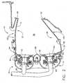
- FIG. 1 shows a gas turbine engine combustor indicated generally as 10 which comprises at least one component having a plurality, and more typically a multiplicity, of airflow holes for which the method of this invention is useful.
- combustor 10 includes a cowl assembly indicated as 14, an outer combustor liner indicated as 22 and an inner combustor liner indicated generally as 26.
- the outer and inner liners 22 and 26 are disposed between an outer combustor casing 30 and an inner combustor casing 34.
- Outer and inner liners 22 and 26 are generally annular in form about a centerline axis (not shown) and are radially spaced from each other to define a combustion chamber 38 therebetween.
- the outer liner 22 and the outer casing 30 form an outer passage therebetween indicated by arrow 42, while inner liner assembly 26 and the inner casing 34 form an inner passage therebetween indicated by arrow 46.
- Cowl assembly 14 is mounted to the upstream ends of outer and inner liners 22 and 26.
- An annular opening 50 is formed in the cowl assembly 14 for the introduction of compressed air into combustor 10.
- the compressed air is supplied from a compressor (not shown) and is channeled in a direction generally indicated by arrows 54 of FIG. 1 .
- the compressed air passes principally through the opening 50 to support combustion and partially into the outer and inner passages 42 and 46 where it is used to at least partially provide cooling airflow for outer and inner liners 22 and 26.
- Disposed between and interconnecting liners 22 and 26 near their respective upstream ends is an annular dome plate 58.
- a plurality of circumferentially spaced swirler assemblies 62 are mounted in the dome plate 58.
- Each swirler assembly 62 receives compressed air from the opening 50 and fuel from a corresponding fuel tube 66.
- the fuel and air are swirled and mixed by swirler assemblies 62, and the resulting fuel/air mixture is discharged into the combustion chamber 38.
- FIG. 1 illustrates a single annular combustor
- the method of this invention is equally applicable to any type of combustor, including double and triple annular combustors, that use liners with multi-hole film cooling.
- One such representative double annular combustor is shown in FIG. 2 as having two rows of swirler assemblies 62 and corresponding fuel tubes 66, as well as a centershield 68.
- outer and inner liners 22 and 26 each comprise a single wall, metal shell having a generally annular and axially extending configuration.
- outer liner 22 has a hot or combustion surface or side 70 facing the hot combustion gases in the combustion chamber 38 and a cold or air supply surface or side 74 in contact with the relatively cooler air in outer passage 42.
- the inner liner 26 has a hot or combustion surface or side 78 facing the hot combustion gases in the combustion chamber 38 and a cold or air supply surface or side 82 in contact with the relatively cooler air in inner passage 46.
- each of liners 22 and 26 also has respective forward bands indicated generally as 84 and 86, as well as aft leaf seal lips indicated generally 88 and 90, for securing liners 22 and 26 within combustor 10.
- both outer and inner liners 22 and 26 have formed therein a large number of airflow holes.
- inner liner 26 having a row of relatively small nugget cooling holes indicated generally as 94 at the forward end of the liner, several arranged arrays comprising a plurality of rows of smaller transpiration cooling holes indicated generally as 98, and at least one row of larger dilution holes indicated generally as 102 that extend from the cold side 82 (or 74 in the case of outer liner 22) to the hot side 78 (or 70 in the case of outer liner 22).
- Dilution holes 102 introduce air into combustor chamber 38, are generally far smaller in number than nugget holes 94, and especially transpiration holes 98, and have a cross-sectional area that is substantially greater than the cross-sectional area of holes 94 and 98.
- the transpiration holes 98 are typically axially slanted from the cold side 74, 82 to the respective hot side 70, 78 in the downstream direction.
- air from the outer and inner passages 42 and 46 passing through the nugget and transpiration holes 94 and 98 is directed downstream so as to form a cooling film on the hot side 70, 78 of each liner 22 and 26.
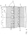
- nugget holes 94 a representative arrangement of nugget holes 94, transpiration holes 98 and dilution holes 102 is shown for inner liner 26.
- a circumferentially extending row indicated as 106 of nugget holes 94 is formed at the upstream end of the liner, with many circumferentially extending rows of laterally spaced transpiration holes 98 indicated generally as 110 being formed and arrayed after nugget hole row 106.
- the nugget holes 94 in row 106 and the transpiration holes 98 in rows 110 typically have a diameter of from about 0.01 to about 0.05 inches (from about 254 to about 1270 microns), more typically from about 0.02 to about 0.03 inches (from about 508 to about 762 microns), and a spacing therebetween of from about 3 to about 10 hole diameters.
- a circumferentially extending row indicated as 114 of primary dilution holes 102 is located towards the upstream end of liner 26, with a circumferentially extending row indicated as 118 of secondary dilution holes located downstream of the primary dilution holes.
- Primary dilution holes 114 and secondary dilution holes 118 typically have a diameter of from about 0.1 to about 0.75 inches(from about 2.5 to about 19 mm.), with the primary dilution holes 114 typically being larger in diameter than the secondary dilution holes 118.
- a cross-section of one such transpiration cooling hole formed in outer liner 22 that is indicated as 122, and extends at a slanted angle downwardly towards the downstream end from cold side 74 to hot side 70 of liner 22.
- the cross-section for such a transpiration cooling hole formed in inner liner 26 would be similar, i.e., extending at a slanted angle upwardly towards the downstream end from cold side 82 to hot side 78 of liner 26.
- hot side 70 typically has formed thereon an additive thermal barrier coating (TBC) indicated generally as 126.
- TBC additive thermal barrier coating
- an overlay metallic coating indicated as 130 is deposited (e.g., sprayed) by an apparatus (not shown) using thermal spray deposition techniques on the cold or air supply side 70.
- the particular spray angle indicated as 134 for depositing coating 130 can depend on a variety of factors, including the slanted angle of hole 122, etc.
- the spray angle 134 for depositing coating 130 can be the same or similar to that of the slanted angle of hole 122, or can be different from that of the slanted angle of hole 122.
- Coating 130 can be deposited to any desired thickness, but is typically deposited to a thickness in the range of from about 1 to about 10 mils (from about 25 to about 254 microns), more typically from about 2 to about 7 mils (from about 51 to about 178 microns), i.e., is relatively thin.
- a portion of coating 130 enters hole 122 at the cold side 74 end thereof, and partially fills hole 122, as indicated by 138.
- the coating 130 can be applied in such a manner so as to restrict the airflow through a larger or smaller quantity or number of holes 122, so as to restrict the airflow through a specified, defined or otherwise selected pattern (e.g., row(s), array(s), area(s), etc.) of holes 122, etc., or any combination thereof.
- the airflow of liner 22 (or 26) can be controlled and adjusted within desired limits or specifications depending upon the number of holes 122 that are partially filled with the portion 138 of coating 130, the pattern of such holes 122 that are filled with the portion 138 of coating 130, and/or the degree to which holes 122 are partially filled with the portion 138 of coating 130.
- airflow hole sizes and airflow passage areas are typically controlled tightly with regard to both upper and lower airflow limits or specifications.
- insufficient cooling airflow or area could result in reduced component durability.
- excessive cooling airflow or area could result in detrimental effect on engine performance, operability and ignition..
- This condition is usually the result of at least some of the airflow holes 122 being larger than desired. This can occur as a result of two factors: (1) holes 122 being larger than the specified or desired size or diameter after original manufacture of the turbine component (i.e., an OEM component) such that desired airflow specifications or limits are exceeded; or (2) holes 122 becoming enlarged after original manufacture and during operation of the turbine component such that desired airflow specifications or limits are exceeded.
- the various embodiments of the method of this invention are intended to be applicable to turbine components (e.g., combustor liners 22 and 26) that have larger than desired holes 122 due to either of factors 1 or 2.
- the diameter of holes 122 can become enlarged (i.e., factor 2) for a variety of reasons, thus increasing the airflow through outer and inner liners 22 and 26.
- enlargement of holes 122 can result from the various processes that are used to perform repairs on outer and inner liners 22 and 26, as well as the manner in which holes 122 are formed. This is exemplified by FIGs. 6 and 7.
- FIG. 6 shows a hole 122 formed by a special machining process, such as laser or electrical discharge machine (EDM) drilling.
- EDM electrical discharge machine
- liners 22, 26 are typically subjected to dry or wet grit blasting with an abrasive media such as alumina particles.
- an abrasive media such as alumina particles.
- the abrasive media is suspended in a liquid, typically water, and then sprayed at high velocity to remove TBC 126.
- recast layer 146 is typically partially or completely removed, thus increasing or enlarging the effective diameter of hole 122 from that indicated by double headed arrow 150 (see FIG. 6 ), to that indicated by double headed arrow 154 (see FIG. 7 ).
- diameter 154 of these enlarged holes 122 can be reduced to adjust and control airflow therethrough.
- the Caldwell et al method includes the steps of: (1) developing a predetermined pressure drop across holes 122 prior to applying coating 130; (2) calculating the airflow through holes 122 resulting from the predetermined pressure; (3) depositing a selected thickness of coating 130 based on the measured airflow through holes 122 so that airflow through holes 122 after depositing the coating 130 is within a preselected range of airflows.
- the minimum airflow of the preselected range of desired airflows is typically selected to provide sufficient airflow through holes 122 to maintain liners 22 and 26 below a selected maximum temperature during engine operation. This maximum temperature is calculated to provide an environment in which liners 22 and 26 life requirements will be met.
- the maximum airflow of the range is typically selected to ensure sufficient airflow through other components within the gas turbine engine to maintain the other components below maximum temperatures at which their respective life requirements are met. Local airflow changes could also cause a detrimental effect on component life as a result of excessive gradient temperatures and can also be corrected according to this embodiment of this invention.
- the turbine component such as combustor liner 22, 26 is checked by a pressure flow stand, before and after coating 130 is deposited on cold side 74, 82. After pressurization, and because of the difference in pressure between the upstream and downstream ends of the pressure flow stand, a pressure drop develops across holes 122 of the combustor liner 22, 26. Because the upstream and downstream pressures are known, airflow through holes 122 can be calculated. For a turbine component or portion thereof, this airflow is compared to a preselected range of desired airflows. If the airflow is within the preselected range of desired airflows and the combustor liner 22, 26 otherwise meets desired component specifications or limits, it is then ready (i.e., acceptable) for use.
- additional layers of coating 130 are then deposited on the combustor liner 22, 26.
- the coated combustor liner 22, 26 is again measured for airflow through holes 122 as before and the measured airflow is again compared to the preselected range.
- these steps can be repeated until the measured airflow is within the preselected range of desired airflows.
- the step of depositing coating 130 need be repeated no more than once in this alternative method.
- the minimum airflow of the preselected range of desired airflows is selected to provide sufficient airflow through holes 122 to maintain the turbine component (e.g., combustor 10) below a selected maximum temperature during engine operation. This maximum temperature is calculated to provide an environment in which component life requirements will be met.
- the maximum airflow of the range is selected to ensure that there is sufficient airflow through other components of the gas turbine engine and that the other components are maintained below maximum temperatures at which their respective life requirements are met.
Description
- This invention relates to adjusting the airflow in turbine components, e.g., gas turbine components, having airflow holes by depositing an overlay metallic coating. This invention further relates to the turbine component whose airflow has been adjusted by depositing such an overlay metallic coating.
- Airflow holes are formed in many gas turbine components, such as combustor liners, for transporting film air through the component to typically cool the component and to form a fluid barrier between the component and hot gases traveling in the main flowpath of the engine. In addition to flowing air over the hot surfaces, combustor liner cooling is also provided by a thin layer of cooling air along the inner, combustion side of the liner by directing airflow through an array of very small airflow holes formed in the liner, typically having a diameter of from about 0.02 to about 0.03 inches (from about 508 to about 762 microns). This film cooling is also induced through "nugget" holes that are typically in one row along the forward edge of the liner, and a much greater number of "transpiration" holes that are typically arranged in a plurality of rows across the entire surface of the liner to induce a more uniform airflow. These "transpiration" holes are typically angled or slanted from the "cold" or air supply side, to the "hot" or combustion side of the liner in a downstream direction, and typically have a circumferential orientation. See, for example,
Fig. 2 of commonly assignedU.S. Pat. No. 6,655,149 (Farmer et al), issued December 2, 2003 . This arrangement, commonly referred to as "multi-hole film cooling," reduces the overall liner cooling airflow requirement because the mass flow through the airflow holes dilutes the hot combustion gas next to the liner surface, with the flow through the airflow holes providing convective cooling of the liner walls. In addition to these smaller diameter "nugget" and "transpiration" airflow holes, larger diameter holes (commonly referred to as "dilution holes") to introduce dilution air into the combustion zone are also provided at spaced intervals. See, for example, commonly assignedFig. 2 ofU.S. Pat. No. 6,408,629 (Harris et al), issued June 25, 2002 andFig. 3 ofU.S. Pat. No. 6,655,149 (Farmer et al), issued December 2, 2003 . - The combustion side of these combustion liners can be coated with a thermal barrier coating to help protect the liner from thermal fatigue caused by the hot gas radiation and conduction to the combustor liner or liners. See commonly assigned
U.S. Pat. No. 6,620,457 (Farmer et al), issued September 16, 2003 , which discloses a physical vapor deposition process to thermally insulate the combustor liner. After a period of service, these combustor liners are typically removed from the engine for replacement, repair, cleaning and/or removal of contaminants (e.g., oxidative deposits and residual combustion products), cracking and other thermally induced stresses that the liners have been subjected to. At least some of these cracks run through the various holes, including the smaller "nugget" and "transpiration" holes. - To repair a part or component, or a portion of a part or component, adequate cleaning of the surface thereof is typically required. During cleaning, the thermal barrier coating and contaminants are typically removed from the combustor liners by chemical and/or mechanical processes, for example, a conventional acid strip process. Repair of the combustor liners, and in particular repair of the cracks that typically form in the liners during operation and use, can cause at least some of the very small "nugget" and "transpiration" holes to become obstructed, occluded, plugged, or otherwise blocked which can then require chemical and/or mechanical processes to reopen the holes. The reopening of these airflow holes, as well as the chemical stripping process that removes the coatings and contaminants, can also remove some of metal substrate of the combustor liner where these holes are located, resulting in enlarging of these holes. These enlarged airflow holes can significantly and undesirably increase the airflow of these liners. Indeed, after several cycles of such cleaning and repair, the airflow can be increased to the extent that the combustor liner is no longer usable.
- Problems in controlling airflow can also occur during the original manufacture of the combustor liners. To form typically thousands of these very small "nugget" and "transpiration" holes, and especially at a slanted angle, the liner is typically drilled using special machining processes such as laser beam or electrical discharge machining (EDM) processes. While a certain amount of control can be exercised over the pattern and size of the drilled holes, it is still extremely difficult to provide combustor liners that have a consistent pattern and size of holes such that the airflow rate is within desired limits. In addition, laser or EDM drilling forms a recast layer along the surface of the hole as it is generated. During subsequent stripping and cleaning of the combustor liner, this recast layer can also be removed, thus enlarging the hole and increasing the airflow.
- A method for adjusting airflow in a turbine component having such airflow holes is disclosed in commonly assigned
U.S. Pat. No. 6,408,610 (Caldwell et al), issued June 25, 2002 . This method involves depositing a thermal barrier coating by a physical vapor deposition (PVD) process (e.g., electron beam PVD) on the exterior and/or interior surfaces of the component to at least partially obstruct the airflow through the airflow holes. While this method provides the ability to adjust the airflow through the airflow holes, the physical vapor deposition apparatus, because of its size, may not provide the flexibility needed to use it with some turbine components. In addition, thermal barrier coatings typically comprise ceramic materials that may or may not adhere adequately to the metal surface of the liner over time without an overlay metallic bond coat layer. SeeU.S. Pat. No. 6,620,457 , supra, which discloses spraying NiCrAlY as abond coat layer 110 of from about 4 to about 10 mils on the inner combustion surface 40 of thecombustor liner 14 before depositing the thermal barrier coating 120. - Commonly assigned
US-A-5 941 686 discloses an air cooled gas turbine engine article having a Thermal Barrier Coating, including a plurality of fluid cooling passages through the article wall, having openings sized to maintain desired fluid flow, unobstructed by coating within the passage at an exit opening. The passages have first or inlet openings, which establishes the amount of fluid flow through the passages, and second openings through which the flow exits the passages through the wall surface on which the coating is deposited. - Accordingly, it would be desirable to be able to economically and evenly adjust the airflow in turbine components (e.g., gas turbine components), such as combustor liners, having a large quantity of smaller diameter airflow holes where the air volume of the respective holes has been changed, and especially enlarged, during subsequent repair, replacement, cleaning, and/or removal processes. It would also be desirable to be able to adjust the airflow through turbine components after final manufacture without removing, or substantially removing, previously applied thermal barrier coatings. It would additionally be desirable to be able to adjust the airflow in turbine components, such as combustor liners, having airflow holes that, when originally manufactured (i.e., an OEM component), require airflow adjustment to be within acceptable limits. It would be further desirable to be able to have the flexibility to adjust the airflow in a variety of turbine components having airflow holes and especially a component having many thousands of airflow holes as, for example, a combustor liner.
- An embodiment of this invention relates to a method for providing the desired degree of airflow in a turbine component (e.g., a gas turbine component) having a plurality of airflow holes a cold surface and a hot surface. This method comprises the step of depositing an overlay metallic coating on the surface of the turbine component in a manner such that at least some of the airflow holes are partially filled such that the volume of the partially filled airflow holes is changed so as to provide the desired airflow through the turbine component. The overlay coating is a metallic coating deposited on the cold surface by thermal spray deposition.
- The method and turbine component of this invention provides a number of benefits and advantages. These include but are not limited to: (1) providing the ability to repair or correct the airflow in turbine components, such as combustor liners, having a plurality of airflow holes so as to come within desired airflow specification or limits; (2) providing the ability to locally correct or change the airflow within specific regions or areas having such airflow holes as needed or desired, including controlling such airflow within desired specifications or limits; (3) recovering and repairing previously used or operational combustor liners and other turbine components having a plurality of airflow holes in a cost effective and efficient manner; (4) performing such recovery or repair of the turbine component without having to remove original or restored thermal barrier coatings or otherwise undesirably altering the physical or chemical properties, or physical dimensions of the component; and (5) recovering or salvaging turbine components manufactured with airflow greater than desired operational specifications or limits.
- Embodiments of the invention will now be described, by way of example, with reference to the accompanying drawings, in which:
-
FIG. 1 is a cutaway perspective view of a representative gas turbine combustor having combustor liners for which the method of this invention is useful. -
FIG. 2 is an enlarged sectional view of a double annular combustor having combustor liners for which the method of this invention is useful. -
FIG. 3 is an enlarged sectional view of the inner combustor liner shown inFIG. 2 . -
FIG 4 is an enlarged fragmentary view of the outer surface of the combustor liner ofFIG. 3 showing a representative arrangement of airflow holes. -
FIG. 5 is an enlarged sectional view of the outer combustor liner showing a coating applied by the method of this invention. -
FIG. 6 is a view similar to that ofFIG. 5 showing the recast layer formed by either laser or EDM drilling of a slanted transpiration cooling hole. -
FIG 7 is a view similar to that ofFIG. 6 showing the recast layer removed from the transpiration cooling hole. - As used herein, the term "turbine component having a plurality of airflow holes" refers to any turbine engine component (e.g., gas turbine engine component) having at least two and typically a multiplicity of airflow holes through which air is circulated, typically for the purpose of cooling the component. Representative examples of such turbine components include but are not limited to turbine shrouds, such as, for example, those disclosed in commonly assigned
U.S. Pat No. 5,127,793 (Walker et al), issued July 7, 1992 ;U.S. Pat No. 5,169,287 (Proctor et al), issued December 8, 1992 ;U.S. Pat. No. 6,340,285 (Gonyou et al), issued January 22, 2002 ); andU.S. Pat. No. 6,354,795 (White et al), issued March 12, 2002 , combustor liners, such as, for example, those disclosed in commonly assignedU.S. Pat No. 6,408,629 (Harris et al), issued June 25, 2002 ;U.S. Pat No. 6,655,149 (Farmer et al), issued December 2, 2003 ; andU.S. Pat. No. 6,620,457 (Farmer et al), issued September 16, 2003 , heat shields, vanes, impingement rings, nozzles, etc. This invention is particularly directed at combustor liners and other turbine components having a plurality, or more typically a multiplicity, of such airflow holes, and more particularly combustor liners having a plurality, or more typically a multiplicity, of transpiration cooling airflow holes to provide what is commonly referred to as "multi-hole film cooling." See, for example,U.S. Pat No. 6,408,629 , supra;U.S. Pat No. 6,655,149 , supra; andU.S. Pat. No. 6,620,457 , supra. - As used herein, the term "airflow hole(s)" refers to holes through which air passes or otherwise circulates to adjust, change or otherwise control the airflow in the turbine component, and which typically provide or induce, directly or indirectly, cooling of the turbine components, i.e., are cooling holes, such as nugget holes or transpiration holes.
- As used herein, the term "overlay metallic coating" refers to any metallic coating that can be sprayed, applied or otherwise deposited by thermal spray deposition techniques and are often used to deposit additive metallic coatings on a metal substrate before thermal barrier coating materials are deposited. These overlay metallic coatings include MCrAlY coatings wherein M is a metal such as iron, nickel, platinum, cobalt or alloys thereof, etc. Typically, the overlay metallic coating used in this invention is a NiCrAlY coating.
- As used herein, the term "thermal spray deposition methods" refers to any method for spraying, applying or otherwise depositing the overlay metallic coating that involves heating and typically at least partial or complete thermal melting of the overlay coating material and depositing of the heated/melted material, typically by entrainment in a heated gas stream, onto the metal substrate to be coated. Suitable thermal spray deposition techniques include plasma spray, such as air plasma spray (APS) and vacuum plasma spray (VPS), high velocity oxy-fuel (HVOF) spray, detonation spray, wire spray, etc., as well as combinations of these techniques. A particularly suitable thermal spray deposition technique for use herein is plasma spray. Suitable plasma spray techniques are well known to those skilled in the art. See, for example, Kirk-Othmer Encyclopedia of Chemical Technology, 3rd Ed., Vol. 15, page 255, and references noted therein, as well as
U.S. Pat. No. 5,332,598 (Kawasaki et al), issued July 26, 1994 ;U.S. Pat. No. 5,047,612 (Savkar et al) issued September 10, 1991 ; andU.S. Pat. No. 4,741,286 (Itoh et al), issued May 3, 1998 which are instructive in regard to various aspects of plasma spraying suitable for use herein. In general, typical plasma spray techniques involve the formation of a high-temperature plasma, which produces a thermal plume. The overlay metallic coating material, e.g., as a powder, is fed into the plume, and the plume is directed toward the base metal substrate to be coated. Various details of such plasma spray coating techniques are also well-known to those skilled in the art, including various relevant steps and process parameters such as cleaning of the surface of the base metal substrate prior to deposition, plasma spray parameters such as spray distances (gun-to-substrate), selection of the number of spray-passes, powder feed rates, particle velocity, torch power, plasma gas selection, oxidation control to adjust oxide stoichiometry, angle-of-deposition, post-treatment of the applied coating, and the like. Suitable plasma spray systems are described in, for example,U.S. Pat. No. 5,047,612 (Savkar et al ), supra. - As used herein, the term "comprising" means various compositions, components, materials, layers, steps, etc., can be conjointly employed in this invention. Accordingly, the term "comprising" encompasses the more restrictive terms "consisting essentially of" and "consisting of."
- All amounts, parts, ratios and percentages used herein are by weight unless otherwise specified.
- The various embodiments of the method and turbine component of this invention are further illustrated by reference to the drawings as described hereafter. Referring to the drawings,
FIG. 1 shows a gas turbine engine combustor indicated generally as 10 which comprises at least one component having a plurality, and more typically a multiplicity, of airflow holes for which the method of this invention is useful. As shown inFIG. 1 ,combustor 10 includes a cowl assembly indicated as 14, an outer combustor liner indicated as 22 and an inner combustor liner indicated generally as 26. The outer andinner liners outer combustor casing 30 and aninner combustor casing 34. Outer andinner liners combustion chamber 38 therebetween. Theouter liner 22 and theouter casing 30 form an outer passage therebetween indicated byarrow 42, whileinner liner assembly 26 and theinner casing 34 form an inner passage therebetween indicated byarrow 46. -
Cowl assembly 14 is mounted to the upstream ends of outer andinner liners annular opening 50 is formed in thecowl assembly 14 for the introduction of compressed air intocombustor 10. The compressed air is supplied from a compressor (not shown) and is channeled in a direction generally indicated byarrows 54 ofFIG. 1 . The compressed air passes principally through theopening 50 to support combustion and partially into the outer andinner passages inner liners liners annular dome plate 58. A plurality of circumferentially spacedswirler assemblies 62 are mounted in thedome plate 58. Eachswirler assembly 62 receives compressed air from theopening 50 and fuel from a correspondingfuel tube 66. The fuel and air are swirled and mixed byswirler assemblies 62, and the resulting fuel/air mixture is discharged into thecombustion chamber 38. It should be noted that althoughFIG. 1 illustrates a single annular combustor, the method of this invention is equally applicable to any type of combustor, including double and triple annular combustors, that use liners with multi-hole film cooling. One such representative double annular combustor is shown inFIG. 2 as having two rows ofswirler assemblies 62 andcorresponding fuel tubes 66, as well as acentershield 68. - The outer and
inner liners FIGs. 1 and2 ,outer liner 22 has a hot or combustion surface orside 70 facing the hot combustion gases in thecombustion chamber 38 and a cold or air supply surface orside 74 in contact with the relatively cooler air inouter passage 42. Similarly, theinner liner 26 has a hot or combustion surface orside 78 facing the hot combustion gases in thecombustion chamber 38 and a cold or air supply surface orside 82 in contact with the relatively cooler air ininner passage 46. As shown particularly inFIG. 2 , each ofliners liners combustor 10. - As shown in
FIG. 1 , both outer andinner liners FIG. 3 which shows, for illustrative purposes,inner liner 26 having a row of relatively small nugget cooling holes indicated generally as 94 at the forward end of the liner, several arranged arrays comprising a plurality of rows of smaller transpiration cooling holes indicated generally as 98, and at least one row of larger dilution holes indicated generally as 102 that extend from the cold side 82 (or 74 in the case of outer liner 22) to the hot side 78 (or 70 in the case of outer liner 22). Dilution holes 102 introduce air intocombustor chamber 38, are generally far smaller in number than nugget holes 94, and especially transpiration holes 98, and have a cross-sectional area that is substantially greater than the cross-sectional area ofholes cold side hot side inner passages hot side liner - Referring to
FIG. 4 , and viewed from the hot orcombustion side 78, a representative arrangement of nugget holes 94, transpiration holes 98 and dilution holes 102 is shown forinner liner 26. As shown inFIG. 4 , and proceeding from the upstream end to the downstream end ofliner 26, a circumferentially extending row indicated as 106 of nugget holes 94 is formed at the upstream end of the liner, with many circumferentially extending rows of laterally spaced transpiration holes 98 indicated generally as 110 being formed and arrayed afternugget hole row 106. The nugget holes 94 inrow 106 and the transpiration holes 98 inrows 110 typically have a diameter of from about 0.01 to about 0.05 inches (from about 254 to about 1270 microns), more typically from about 0.02 to about 0.03 inches (from about 508 to about 762 microns), and a spacing therebetween of from about 3 to about 10 hole diameters. - As also shown in
FIG. 4 , a circumferentially extending row indicated as 114 of primary dilution holes 102 is located towards the upstream end ofliner 26, with a circumferentially extending row indicated as 118 of secondary dilution holes located downstream of the primary dilution holes. Primary dilution holes 114 and secondary dilution holes 118 typically have a diameter of from about 0.1 to about 0.75 inches(from about 2.5 to about 19 mm.), with the primary dilution holes 114 typically being larger in diameter than the secondary dilution holes 118. Depending upon the diameter and spacing, there are typically from about 20 to about 60 primary dilution holes 114 and from about 20 to about 120 secondary dilution holes 118 formed in the liner. - Referring to
FIG. 5 , a cross-section of one such transpiration cooling hole formed inouter liner 22 that is indicated as 122, and extends at a slanted angle downwardly towards the downstream end fromcold side 74 tohot side 70 ofliner 22. (The cross-section for such a transpiration cooling hole formed ininner liner 26 would be similar, i.e., extending at a slanted angle upwardly towards the downstream end fromcold side 82 tohot side 78 ofliner 26.) As shown inFIG. 5 ,hot side 70 typically has formed thereon an additive thermal barrier coating (TBC) indicated generally as 126. To adjust the airflow throughhole 122, an overlay metallic coating indicated as 130 is deposited (e.g., sprayed) by an apparatus (not shown) using thermal spray deposition techniques on the cold orair supply side 70. The particular spray angle indicated as 134 for depositingcoating 130 can depend on a variety of factors, including the slanted angle ofhole 122, etc. For example, and as shown inFIG. 5 , thespray angle 134 for depositingcoating 130 can be the same or similar to that of the slanted angle ofhole 122, or can be different from that of the slanted angle ofhole 122. - Coating 130 can be deposited to any desired thickness, but is typically deposited to a thickness in the range of from about 1 to about 10 mils (from about 25 to about 254 microns), more typically from about 2 to about 7 mils (from about 51 to about 178 microns), i.e., is relatively thin. Depending upon the
spray angle 134 at which the overlay metallic coating is deposited, a portion ofcoating 130 entershole 122 at thecold side 74 end thereof, and partially fillshole 122, as indicated by 138. Because thelip end 142 ofhole 122 is partially filled with theportion 138 ofcoating 130, this effectively reduces the diameter ofhole 122, and thus partially obstructs or restricts the effective area or volume ofhole 122, thus reducing the volume of airflow that can entersuch holes 122 from passage 42 (or frompassage 46 adjacent to liner 26) for a given pressure drop. As a result, the airflow from passage 42 (or 46 adjacent to liner 26) intoholes 122 is reduced. Thecoating 130 can be applied in such a manner so as to restrict the airflow through a larger or smaller quantity or number ofholes 122, so as to restrict the airflow through a specified, defined or otherwise selected pattern (e.g., row(s), array(s), area(s), etc.) ofholes 122, etc., or any combination thereof. In this manner, the airflow of liner 22 (or 26) can be controlled and adjusted within desired limits or specifications depending upon the number ofholes 122 that are partially filled with theportion 138 ofcoating 130, the pattern ofsuch holes 122 that are filled with theportion 138 ofcoating 130, and/or the degree to which holes 122 are partially filled with theportion 138 ofcoating 130. - In gas turbine components such as
liners combustion chamber 38, insufficient cooling airflow or area could result in reduced component durability. In addition, excessive cooling airflow or area could result in detrimental effect on engine performance, operability and ignition.. This condition is usually the result of at least some of the airflow holes 122 being larger than desired. This can occur as a result of two factors: (1)holes 122 being larger than the specified or desired size or diameter after original manufacture of the turbine component (i.e., an OEM component) such that desired airflow specifications or limits are exceeded; or (2)holes 122 becoming enlarged after original manufacture and during operation of the turbine component such that desired airflow specifications or limits are exceeded. The various embodiments of the method of this invention are intended to be applicable to turbine components (e.g.,combustor liners 22 and 26) that have larger than desiredholes 122 due to either of factors 1 or 2. - The diameter of
holes 122 can become enlarged (i.e., factor 2) for a variety of reasons, thus increasing the airflow through outer andinner liners holes 122 can result from the various processes that are used to perform repairs on outer andinner liners FIGs. 6 and 7. FIG. 6 shows ahole 122 formed by a special machining process, such as laser or electrical discharge machine (EDM) drilling. As a result of laser or EDM drilling, a recast layer of material indicated generally as 146 is formed on the surface ofhole 122. During the process of cleaning a portion of a component, for example,TBC 126,liners TBC 126. As a result, and as shown inFIG. 7 , recastlayer 146 is typically partially or completely removed, thus increasing or enlarging the effective diameter ofhole 122 from that indicated by double headed arrow 150 (seeFIG. 6 ), to that indicated by double headed arrow 154 (seeFIG. 7 ). By using an embodiment of the method of this invention previously described with respect toFIG. 5 ,diameter 154 of theseenlarged holes 122 can be reduced to adjust and control airflow therethrough. - An embodiment of the method of this invention for adjusting and controlling the airflow through
holes 122, and thus adjusting and controlling the airflow throughliners holes 122 prior to applyingcoating 130; (b) applyingcoating 130 to thecold side liner 22 and/or 26, as previously described; (c) determining the amount of airflow throughholes 122 after coating 130 has been applied; and (d) repeating steps (b) and (c) as needed until the desired degree of airflow is achieved. An embodiment of such a method can be carried out by appropriate modification of the technique disclosed in commonly assignedU.S. Pat. No. 6,408,610 (Caldwell et al), issued June 28, 2002 . The Caldwell et al method, as modified for use in the embodiment of the method of this invention, includes the steps of: (1) developing a predetermined pressure drop acrossholes 122 prior to applyingcoating 130; (2) calculating the airflow throughholes 122 resulting from the predetermined pressure; (3) depositing a selected thickness ofcoating 130 based on the measured airflow throughholes 122 so that airflow throughholes 122 after depositing thecoating 130 is within a preselected range of airflows. The minimum airflow of the preselected range of desired airflows is typically selected to provide sufficient airflow throughholes 122 to maintainliners liners - In using the Caldwell et al method, as modified for use in the method of this invention (see
FIG. 3 of Caldwell et al patent), the turbine component, such ascombustor liner cold side holes 122 of thecombustor liner holes 122 can be calculated. For a turbine component or portion thereof, this airflow is compared to a preselected range of desired airflows. If the airflow is within the preselected range of desired airflows and thecombustor liner - If, however, the airflow is above the preselected range of desired airflows, additional layers of
coating 130 are then deposited on thecombustor liner coated combustor liner holes 122 as before and the measured airflow is again compared to the preselected range. In one embodiment of this alternative method, these steps can be repeated until the measured airflow is within the preselected range of desired airflows. Typically, the step of depositingcoating 130 need be repeated no more than once in this alternative method. - The minimum airflow of the preselected range of desired airflows is selected to provide sufficient airflow through
holes 122 to maintain the turbine component (e.g., combustor 10) below a selected maximum temperature during engine operation. This maximum temperature is calculated to provide an environment in which component life requirements will be met. The maximum airflow of the range is selected to ensure that there is sufficient airflow through other components of the gas turbine engine and that the other components are maintained below maximum temperatures at which their respective life requirements are met.
Claims (8)
- A method for providing the desired degree of airflow in a turbine component (22, 26) having a plurality of airflow holes (122), a cold surface (74, 82), and a hot surface (70, 78) having a thermal barrier coating thereon, the method comprising the step of depositing an overlay coating (130) on the surface (74, 82) of the turbine component (22, 26) in a manner such that at least some of the airflow holes (122) are partially filled such that the volume of the partially filled holes (122) is changed so as to provide the desired airflow through the turbine component (22, 26), characterized in that the overlay coating is a metallic coating (130) deposited on the cold surface (74, 82) by thermal spray deposition, and in that the coating is applied in such a manner as to restrict the airflow through a selected pattern of holes (122), with the airflow in the component being controlled depending on the number of holes that are partially filled, the pattern of such filled holes, and the degree to which the holes are partially filled with said coating.
- The method of claim 1 wherein the turbine component is a combustor liner having an air supply side (74, 82) and a combustion side (70, 78), wherein the air cooling holes (122) extend from the air supply side (74, 82) to the combustion side (70, 78), and wherein the overlay metallic coating (130) is deposited onto the air supply side (74, 82).
- The method of claim 1 or claim 2 wherein the airflow holes (122) comprise a plurality of rows of transpiration cooling holes (110) having a diameter in the range of from 254 to 1270 microns.
- The method of any of claims 1 to 3 wherein the overlay metallic coating (130) is deposited to a thickness of from 25 to 254 microns.
- The method of any of claims 1 to 4 wherein the overlay metallic coating (130) is deposited by plasma spray.
- The method of any of claims 1 to 5 wherein the overlay metallic coating (130) comprises a MCrAlY coating wherein M is a metal selected from the group consisting of iron, nickel, platinum, cobalt, and alloys thereof.
- The method of any one of claims 1 to 6 wherein a spray angle at which the overlay metallic coating is deposited is such that the coating partially fills the airflow holes (122).
- A method for providing the desired degree of airflow in a turbine component having a plurality of airflow holes (122), including determining the airflow through the component, carrying out the method of any of claims 1 to 7, determining the airflow after deposition of said coating, and if necessary repeating these steps until the airflow is within a preselected range of desired airflows.
Applications Claiming Priority (1)
| Application Number | Priority Date | Filing Date | Title |
|---|---|---|---|
| US10/934,172 US7216485B2 (en) | 2004-09-03 | 2004-09-03 | Adjusting airflow in turbine component by depositing overlay metallic coating |
Publications (2)
| Publication Number | Publication Date |
|---|---|
| EP1632720A1 EP1632720A1 (en) | 2006-03-08 |
| EP1632720B1 true EP1632720B1 (en) | 2014-04-02 |
Family
ID=35427941
Family Applications (1)
| Application Number | Title | Priority Date | Filing Date |
|---|---|---|---|
| EP05255346.8A Active EP1632720B1 (en) | 2004-09-03 | 2005-09-01 | Adjusting airflow in turbine component by depositing an overlay metallic coating |
Country Status (6)
| Country | Link |
|---|---|
| US (1) | US7216485B2 (en) |
| EP (1) | EP1632720B1 (en) |
| JP (1) | JP2006071274A (en) |
| BR (1) | BRPI0503610A (en) |
| CA (1) | CA2517080C (en) |
| SG (1) | SG120305A1 (en) |
Families Citing this family (47)
| Publication number | Priority date | Publication date | Assignee | Title |
|---|---|---|---|---|
| US7614235B2 (en) * | 2005-03-01 | 2009-11-10 | United Technologies Corporation | Combustor cooling hole pattern |
| US7509809B2 (en) * | 2005-06-10 | 2009-03-31 | Pratt & Whitney Canada Corp. | Gas turbine engine combustor with improved cooling |
| GB2429515B (en) * | 2005-08-11 | 2008-06-25 | Rolls Royce Plc | Cooling method and apparatus |
| FR2892180B1 (en) * | 2005-10-18 | 2008-02-01 | Snecma Sa | IMPROVING THE PERFOMANCE OF A COMBUSTION CHAMBER BY MULTIPERFORATING THE WALLS |
| US7631502B2 (en) * | 2005-12-14 | 2009-12-15 | United Technologies Corporation | Local cooling hole pattern |
| US7622160B2 (en) * | 2006-07-28 | 2009-11-24 | General Electric Company | Method for concurrent thermal spray and cooling hole cleaning |
| US8141370B2 (en) * | 2006-08-08 | 2012-03-27 | General Electric Company | Methods and apparatus for radially compliant component mounting |
| US20080148565A1 (en) * | 2006-12-22 | 2008-06-26 | Edward John Emilianowicz | Methods for making combustor liner replacement panels |
| DE102007048484A1 (en) * | 2007-10-09 | 2009-04-16 | Man Turbo Ag | Hot gas-guided component of a turbomachine |
| US8256223B2 (en) * | 2007-10-16 | 2012-09-04 | United Technologies Corporation | Ceramic combustor liner panel for a gas turbine engine |
| US20090142548A1 (en) * | 2007-10-18 | 2009-06-04 | David Bruce Patterson | Air cooled gas turbine components and methods of manufacturing and repairing the same |
| FR2922630B1 (en) * | 2007-10-22 | 2015-11-13 | Snecma | COMBUSTION CHAMBER WALL WITH OPTIMIZED DILUTION AND COOLING, COMBUSTION CHAMBER AND TURBOMACHINE WHILE ENHANCED |
| US20100281868A1 (en) * | 2007-12-28 | 2010-11-11 | General Electric Company | Gas turbine engine combuster |
| US8307657B2 (en) * | 2009-03-10 | 2012-11-13 | General Electric Company | Combustor liner cooling system |
| US20100329887A1 (en) * | 2009-06-26 | 2010-12-30 | Andy Eifert | Coolable gas turbine engine component |
| US9890647B2 (en) * | 2009-12-29 | 2018-02-13 | Rolls-Royce North American Technologies Inc. | Composite gas turbine engine component |
| JP5578864B2 (en) | 2010-01-20 | 2014-08-27 | 三菱重工業株式会社 | Repair method of wall member with flow path |
| EP2444590B1 (en) * | 2010-10-19 | 2014-08-06 | Siemens Aktiengesellschaft | Method for coating cooling holes |
| US8673397B2 (en) * | 2010-11-10 | 2014-03-18 | General Electric Company | Methods of fabricating and coating a component |
| JP5726545B2 (en) * | 2011-01-24 | 2015-06-03 | 株式会社東芝 | Transition piece damage repair method and transition piece |
| US10113435B2 (en) * | 2011-07-15 | 2018-10-30 | United Technologies Corporation | Coated gas turbine components |
| FR2981733B1 (en) * | 2011-10-25 | 2013-12-27 | Snecma | AIRCRAFT TURBOMACHINE COMBUSTION CHAMBER MODULE AND METHOD FOR DESIGNING THE SAME |
| FR2982008B1 (en) * | 2011-10-26 | 2013-12-13 | Snecma | ANNULAR ROOM OF COMBUSTION CHAMBER WITH IMPROVED COOLING AT THE PRIMARY HOLES AND DILUTION HOLES |
| US9175402B2 (en) * | 2012-07-30 | 2015-11-03 | General Electric Company | Turbine repair process, repaired coating, and repaired turbine component |
| US10060630B2 (en) * | 2012-10-01 | 2018-08-28 | Ansaldo Energia Ip Uk Limited | Flamesheet combustor contoured liner |
| CN104755844B (en) * | 2012-10-24 | 2017-11-07 | 通用电器技术有限公司 | Sequential combustion with diluent gas blender |
| EP2735796B1 (en) * | 2012-11-23 | 2020-01-01 | Ansaldo Energia IP UK Limited | Wall of a hot gas path component of a gas turbine and method for enhancing operational behaviour of a gas turbine |
| US20140157783A1 (en) * | 2012-12-10 | 2014-06-12 | General Electric Company | System for Protecting an Inner Wall of a Combustor |
| US20140174091A1 (en) * | 2012-12-21 | 2014-06-26 | United Technologies Corporation | Repair procedure for a gas turbine engine via variable polarity welding |
| WO2014149119A2 (en) | 2013-03-15 | 2014-09-25 | Rolls-Royce Corporation | Gas turbine engine combustor liner |
| WO2014143209A1 (en) | 2013-03-15 | 2014-09-18 | Rolls-Royce Corporation | Gas turbine engine combustor liner |
| US10704424B2 (en) | 2013-11-04 | 2020-07-07 | Raytheon Technologies Corporation | Coated cooling passage |
| EP3077728B8 (en) | 2013-12-06 | 2021-03-31 | Raytheon Technologies Corporation | Gas turbine engine combustor having co-swirl orientation of combustor effusion passages, and method |
| US10934853B2 (en) | 2014-07-03 | 2021-03-02 | Rolls-Royce Corporation | Damage tolerant cooling of high temperature mechanical system component including a coating |
| WO2016099805A2 (en) * | 2014-11-21 | 2016-06-23 | General Electric Technology Gmbh | Flamesheet combustor contoured liner |
| US10132498B2 (en) * | 2015-01-20 | 2018-11-20 | United Technologies Corporation | Thermal barrier coating of a combustor dilution hole |
| US10563578B2 (en) * | 2015-02-18 | 2020-02-18 | Mra Systems, Llc | Acoustic liners and method of shaping an inlet of an acoustic liner |
| US10670267B2 (en) * | 2015-08-14 | 2020-06-02 | Raytheon Technologies Corporation | Combustor hole arrangement for gas turbine engine |
| US10472972B2 (en) | 2015-12-01 | 2019-11-12 | General Electric Company | Thermal management of CMC articles having film holes |
| US10041677B2 (en) | 2015-12-17 | 2018-08-07 | General Electric Company | Combustion liner for use in a combustor assembly and method of manufacturing |
| JP6026028B1 (en) * | 2016-03-10 | 2016-11-16 | 三菱日立パワーシステムズ株式会社 | Combustor panel, combustor, combustion apparatus, gas turbine, and method for cooling combustor panel |
| US10443395B2 (en) | 2016-03-18 | 2019-10-15 | General Electric Company | Component for a turbine engine with a film hole |
| DE102016219424A1 (en) * | 2016-10-06 | 2018-04-12 | Rolls-Royce Deutschland Ltd & Co Kg | Combustion chamber arrangement of a gas turbine and aircraft gas turbine |
| FR3080168B1 (en) * | 2018-04-13 | 2020-03-20 | Safran Aircraft Engines | ASSEMBLY FOR A TURBOMACHINE COMBUSTION CHAMBER |
| US10815783B2 (en) | 2018-05-24 | 2020-10-27 | General Electric Company | In situ engine component repair |
| US11407067B2 (en) | 2018-06-29 | 2022-08-09 | Pratt & Whitney Canada Corp. | Method for repairing a part |
| US11585224B2 (en) | 2020-08-07 | 2023-02-21 | General Electric Company | Gas turbine engines and methods associated therewith |
Family Cites Families (31)
| Publication number | Priority date | Publication date | Assignee | Title |
|---|---|---|---|---|
| US4338360A (en) * | 1980-05-01 | 1982-07-06 | General Motors Corporation | Method for coating porous metal structure |
| US4743462A (en) * | 1986-07-14 | 1988-05-10 | United Technologies Corporation | Method for preventing closure of cooling holes in hollow, air cooled turbine engine components during application of a plasma spray coating |
| US5724816A (en) * | 1996-04-10 | 1998-03-10 | General Electric Company | Combustor for a gas turbine with cooling structure |
| US5771577A (en) * | 1996-05-17 | 1998-06-30 | General Electric Company | Method for making a fluid cooled article with protective coating |
| US5822853A (en) * | 1996-06-24 | 1998-10-20 | General Electric Company | Method for making cylindrical structures with cooling channels |
| US5902647A (en) * | 1996-12-03 | 1999-05-11 | General Electric Company | Method for protecting passage holes in a metal-based substrate from becoming obstructed, and related compositions |
| US6042879A (en) * | 1997-07-02 | 2000-03-28 | United Technologies Corporation | Method for preparing an apertured article to be recoated |
| JP2001521989A (en) * | 1997-11-03 | 2001-11-13 | シーメンス アクチエンゲゼルシヤフト | Method for forming a film and apparatus for performing the method |
| GB9723762D0 (en) * | 1997-11-12 | 1998-01-07 | Rolls Royce Plc | A method of coating a component |
| US6145319A (en) * | 1998-07-16 | 2000-11-14 | General Electric Company | Transitional multihole combustion liner |
| US6210488B1 (en) * | 1998-12-30 | 2001-04-03 | General Electric Company | Method of removing a thermal barrier coating |
| US6480629B1 (en) * | 1999-04-06 | 2002-11-12 | Koninklijke Philips Electronics N.V. | Motion estimation method using orthogonal-sum block matching |
| DE69911948T2 (en) * | 1999-08-09 | 2004-11-04 | Alstom Technology Ltd | Method for closing cooling openings of a gas turbine component |
| SG127668A1 (en) * | 1999-11-24 | 2006-12-29 | Gen Electric | Method for thermal barrier coating |
| US6368060B1 (en) * | 2000-05-23 | 2002-04-09 | General Electric Company | Shaped cooling hole for an airfoil |
| DE60042061D1 (en) * | 2000-05-31 | 2009-06-04 | Alstom Technology Ltd | Method for adjusting the size of cooling holes of a component of a gas turbine |
| US6408610B1 (en) * | 2000-07-18 | 2002-06-25 | General Electric Company | Method of adjusting gas turbine component cooling air flow |
| US6339879B1 (en) * | 2000-08-29 | 2002-01-22 | General Electric Company | Method of sizing and forming a cooling hole in a gas turbine engine component |
| US6408629B1 (en) * | 2000-10-03 | 2002-06-25 | General Electric Company | Combustor liner having preferentially angled cooling holes |
| US6434823B1 (en) * | 2000-10-10 | 2002-08-20 | General Electric Company | Method for repairing a coated article |
| US6573474B1 (en) * | 2000-10-18 | 2003-06-03 | Chromalloy Gas Turbine Corporation | Process for drilling holes through a thermal barrier coating |
| US6551061B2 (en) * | 2001-03-27 | 2003-04-22 | General Electric Company | Process for forming micro cooling channels inside a thermal barrier coating system without masking material |
| US6499949B2 (en) * | 2001-03-27 | 2002-12-31 | Robert Edward Schafrik | Turbine airfoil trailing edge with micro cooling channels |
| US6620457B2 (en) * | 2001-07-13 | 2003-09-16 | General Electric Company | Method for thermal barrier coating and a liner made using said method |
| US6513331B1 (en) * | 2001-08-21 | 2003-02-04 | General Electric Company | Preferential multihole combustor liner |
| US7204019B2 (en) * | 2001-08-23 | 2007-04-17 | United Technologies Corporation | Method for repairing an apertured gas turbine component |
| US6663919B2 (en) * | 2002-03-01 | 2003-12-16 | General Electric Company | Process of removing a coating deposit from a through-hole in a component and component processed thereby |
| US6749396B2 (en) * | 2002-06-17 | 2004-06-15 | General Electric Company | Failsafe film cooled wall |
| US6847004B2 (en) * | 2003-01-10 | 2005-01-25 | General Electric Company | Process of removing a ceramic coating deposit in a surface hole of a component |
| US6723951B1 (en) * | 2003-06-04 | 2004-04-20 | Siemens Westinghouse Power Corporation | Method for reestablishing holes in a component |
| US20050220618A1 (en) * | 2004-03-31 | 2005-10-06 | General Electric Company | Counter-bored film-cooling holes and related method |
-
2004
- 2004-09-03 US US10/934,172 patent/US7216485B2/en active Active
-
2005
- 2005-08-22 BR BRPI0503610-0A patent/BRPI0503610A/en not_active Application Discontinuation
- 2005-08-25 CA CA2517080A patent/CA2517080C/en not_active Expired - Fee Related
- 2005-08-29 SG SG200505530A patent/SG120305A1/en unknown
- 2005-08-31 JP JP2005250507A patent/JP2006071274A/en active Pending
- 2005-09-01 EP EP05255346.8A patent/EP1632720B1/en active Active
Also Published As
| Publication number | Publication date |
|---|---|
| US20060059918A1 (en) | 2006-03-23 |
| CA2517080C (en) | 2013-10-08 |
| SG120305A1 (en) | 2006-03-28 |
| JP2006071274A (en) | 2006-03-16 |
| US7216485B2 (en) | 2007-05-15 |
| EP1632720A1 (en) | 2006-03-08 |
| CA2517080A1 (en) | 2006-03-03 |
| BRPI0503610A (en) | 2006-04-18 |
Similar Documents
| Publication | Publication Date | Title |
|---|---|---|
| EP1632720B1 (en) | Adjusting airflow in turbine component by depositing an overlay metallic coating | |
| EP0916445B1 (en) | A method of coating a component | |
| US20140248425A1 (en) | Air cooled gas turbine components and methods of manufacturing and repairing same | |
| EP3009744B1 (en) | A liner element for a combustor, and a related method | |
| US8661826B2 (en) | Combustion apparatus | |
| JP4108152B2 (en) | Fluid cooling product having protective film and method for producing the same | |
| US8672613B2 (en) | Components with conformal curved film holes and methods of manufacture | |
| EP1245787B1 (en) | Cooling system for a coated turbine blade tip | |
| US7008178B2 (en) | Inboard cooled nozzle doublet | |
| EP1564495B1 (en) | Combustor assembly and method for making a combustor assembly | |
| US7854122B2 (en) | Cooling method and apparatus | |
| US6528118B2 (en) | Process for creating structured porosity in thermal barrier coating | |
| EP1515090A1 (en) | Thick coated combustor liner | |
| JP4959718B2 (en) | Part to be placed in the flow path of a fluid machine and spray method for coating generation | |
| US20160089692A1 (en) | Turbine component coating processes and turbine components | |
| EP1556596A1 (en) | Effusion cooled transition duct with shaped cooling holes | |
| EP2995864B1 (en) | Film cooling circuit for a combustor liner and method of manufacturing the film cooling circuit | |
| EP2935951B1 (en) | Closure of cooling holes with a filling agent | |
| CN110725718A (en) | Turbine engine component with cooling holes | |
| US20230358139A1 (en) | Gas turbine engines and methods associated therewith | |
| US9970660B2 (en) | Liner element for a combustor | |
| GB2461898A (en) | Shield for preventing coating build up | |
| EP1245788A2 (en) | Methods and apparatus for preferential placement of turbine nozzles and shrouds based on inlet conditions | |
| GB2461897A (en) | Shield for preventing coating build up |
Legal Events
| Date | Code | Title | Description |
|---|---|---|---|
| PUAI | Public reference made under article 153(3) epc to a published international application that has entered the european phase |
Free format text: ORIGINAL CODE: 0009012 |
|
| AK | Designated contracting states |
Kind code of ref document: A1 Designated state(s): AT BE BG CH CY CZ DE DK EE ES FI FR GB GR HU IE IS IT LI LT LU LV MC NL PL PT RO SE SI SK TR |
|
| AX | Request for extension of the european patent |
Extension state: AL BA HR MK YU |
|
| 17P | Request for examination filed |
Effective date: 20060908 |
|
| 17Q | First examination report despatched |
Effective date: 20061019 |
|
| AKX | Designation fees paid |
Designated state(s): DE FR GB |
|
| GRAP | Despatch of communication of intention to grant a patent |
Free format text: ORIGINAL CODE: EPIDOSNIGR1 |
|
| INTG | Intention to grant announced |
Effective date: 20131126 |
|
| GRAS | Grant fee paid |
Free format text: ORIGINAL CODE: EPIDOSNIGR3 |
|
| GRAA | (expected) grant |
Free format text: ORIGINAL CODE: 0009210 |
|
| AK | Designated contracting states |
Kind code of ref document: B1 Designated state(s): DE FR GB |
|
| REG | Reference to a national code |
Ref country code: GB Ref legal event code: FG4D |
|
| REG | Reference to a national code |
Ref country code: DE Ref legal event code: R096 Ref document number: 602005043150 Country of ref document: DE Effective date: 20140508 |
|
| REG | Reference to a national code |
Ref country code: DE Ref legal event code: R026 Ref document number: 602005043150 Country of ref document: DE |
|
| PLBI | Opposition filed |
Free format text: ORIGINAL CODE: 0009260 |
|
| 26 | Opposition filed |
Opponent name: SIEMENS AKTIENGESELLSCHAFT Effective date: 20141209 |
|
| PLAX | Notice of opposition and request to file observation + time limit sent |
Free format text: ORIGINAL CODE: EPIDOSNOBS2 |
|
| REG | Reference to a national code |
Ref country code: DE Ref legal event code: R026 Ref document number: 602005043150 Country of ref document: DE Effective date: 20141209 |
|
| PLAF | Information modified related to communication of a notice of opposition and request to file observations + time limit |
Free format text: ORIGINAL CODE: EPIDOSCOBS2 |
|
| PLBB | Reply of patent proprietor to notice(s) of opposition received |
Free format text: ORIGINAL CODE: EPIDOSNOBS3 |
|
| PLAO | Information deleted related to despatch of communication that opposition is rejected |
Free format text: ORIGINAL CODE: EPIDOSDREJ1 |
|
| PLCK | Communication despatched that opposition was rejected |
Free format text: ORIGINAL CODE: EPIDOSNREJ1 |
|
| PLCK | Communication despatched that opposition was rejected |
Free format text: ORIGINAL CODE: EPIDOSNREJ1 |
|
| REG | Reference to a national code |
Ref country code: DE Ref legal event code: R100 Ref document number: 602005043150 Country of ref document: DE |
|
| PLBN | Opposition rejected |
Free format text: ORIGINAL CODE: 0009273 |
|
| STAA | Information on the status of an ep patent application or granted ep patent |
Free format text: STATUS: OPPOSITION REJECTED |
|
| REG | Reference to a national code |
Ref country code: FR Ref legal event code: PLFP Year of fee payment: 12 |
|
| 27O | Opposition rejected |
Effective date: 20160623 |
|
| REG | Reference to a national code |
Ref country code: FR Ref legal event code: PLFP Year of fee payment: 13 |
|
| REG | Reference to a national code |
Ref country code: FR Ref legal event code: PLFP Year of fee payment: 14 |
|
| PGFP | Annual fee paid to national office [announced via postgrant information from national office to epo] |
Ref country code: DE Payment date: 20190820 Year of fee payment: 15 Ref country code: FR Payment date: 20190820 Year of fee payment: 15 |
|
| REG | Reference to a national code |
Ref country code: DE Ref legal event code: R119 Ref document number: 602005043150 Country of ref document: DE |
|
| PG25 | Lapsed in a contracting state [announced via postgrant information from national office to epo] |
Ref country code: DE Free format text: LAPSE BECAUSE OF NON-PAYMENT OF DUE FEES Effective date: 20210401 Ref country code: FR Free format text: LAPSE BECAUSE OF NON-PAYMENT OF DUE FEES Effective date: 20200930 |
|
| P01 | Opt-out of the competence of the unified patent court (upc) registered |
Effective date: 20230414 |
|
| PGFP | Annual fee paid to national office [announced via postgrant information from national office to epo] |
Ref country code: GB Payment date: 20230823 Year of fee payment: 19 |