EP1632664B1 - Cylinder rest internal combustion engine - Google Patents
Cylinder rest internal combustion engine Download PDFInfo
- Publication number
- EP1632664B1 EP1632664B1 EP05017387A EP05017387A EP1632664B1 EP 1632664 B1 EP1632664 B1 EP 1632664B1 EP 05017387 A EP05017387 A EP 05017387A EP 05017387 A EP05017387 A EP 05017387A EP 1632664 B1 EP1632664 B1 EP 1632664B1
- Authority
- EP
- European Patent Office
- Prior art keywords
- cylinder
- valve
- throttle valve
- opening
- throttle
- Prior art date
- Legal status (The legal status is an assumption and is not a legal conclusion. Google has not performed a legal analysis and makes no representation as to the accuracy of the status listed.)
- Expired - Lifetime
Links
Images


Classifications
-
- F—MECHANICAL ENGINEERING; LIGHTING; HEATING; WEAPONS; BLASTING
- F02—COMBUSTION ENGINES; HOT-GAS OR COMBUSTION-PRODUCT ENGINE PLANTS
- F02D—CONTROLLING COMBUSTION ENGINES
- F02D13/00—Controlling the engine output power by varying inlet or exhaust valve operating characteristics, e.g. timing
- F02D13/02—Controlling the engine output power by varying inlet or exhaust valve operating characteristics, e.g. timing during engine operation
- F02D13/0203—Variable control of intake and exhaust valves
-
- F—MECHANICAL ENGINEERING; LIGHTING; HEATING; WEAPONS; BLASTING
- F01—MACHINES OR ENGINES IN GENERAL; ENGINE PLANTS IN GENERAL; STEAM ENGINES
- F01L—CYCLICALLY OPERATING VALVES FOR MACHINES OR ENGINES
- F01L1/00—Valve-gear or valve arrangements, e.g. lift-valve gear
- F01L1/12—Transmitting gear between valve drive and valve
- F01L1/14—Tappets; Push rods
- F01L1/143—Tappets; Push rods for use with overhead camshafts
-
- F—MECHANICAL ENGINEERING; LIGHTING; HEATING; WEAPONS; BLASTING
- F01—MACHINES OR ENGINES IN GENERAL; ENGINE PLANTS IN GENERAL; STEAM ENGINES
- F01L—CYCLICALLY OPERATING VALVES FOR MACHINES OR ENGINES
- F01L1/00—Valve-gear or valve arrangements, e.g. lift-valve gear
- F01L1/20—Adjusting or compensating clearance
- F01L1/205—Adjusting or compensating clearance by means of shims or the like
-
- F—MECHANICAL ENGINEERING; LIGHTING; HEATING; WEAPONS; BLASTING
- F01—MACHINES OR ENGINES IN GENERAL; ENGINE PLANTS IN GENERAL; STEAM ENGINES
- F01L—CYCLICALLY OPERATING VALVES FOR MACHINES OR ENGINES
- F01L13/00—Modifications of valve-gear to facilitate reversing, braking, starting, changing compression ratio, or other specific operations
- F01L13/0005—Deactivating valves
-
- F—MECHANICAL ENGINEERING; LIGHTING; HEATING; WEAPONS; BLASTING
- F02—COMBUSTION ENGINES; HOT-GAS OR COMBUSTION-PRODUCT ENGINE PLANTS
- F02D—CONTROLLING COMBUSTION ENGINES
- F02D11/00—Arrangements for, or adaptations to, non-automatic engine control initiation means, e.g. operator initiated
- F02D11/06—Arrangements for, or adaptations to, non-automatic engine control initiation means, e.g. operator initiated characterised by non-mechanical control linkages, e.g. fluid control linkages or by control linkages with power drive or assistance
- F02D11/10—Arrangements for, or adaptations to, non-automatic engine control initiation means, e.g. operator initiated characterised by non-mechanical control linkages, e.g. fluid control linkages or by control linkages with power drive or assistance of the electric type
- F02D11/105—Arrangements for, or adaptations to, non-automatic engine control initiation means, e.g. operator initiated characterised by non-mechanical control linkages, e.g. fluid control linkages or by control linkages with power drive or assistance of the electric type characterised by the function converting demand to actuation, e.g. a map indicating relations between an accelerator pedal position and throttle valve opening or target engine torque
-
- F—MECHANICAL ENGINEERING; LIGHTING; HEATING; WEAPONS; BLASTING
- F02—COMBUSTION ENGINES; HOT-GAS OR COMBUSTION-PRODUCT ENGINE PLANTS
- F02D—CONTROLLING COMBUSTION ENGINES
- F02D13/00—Controlling the engine output power by varying inlet or exhaust valve operating characteristics, e.g. timing
- F02D13/02—Controlling the engine output power by varying inlet or exhaust valve operating characteristics, e.g. timing during engine operation
- F02D13/0257—Independent control of two or more intake or exhaust valves respectively, i.e. one of two intake valves remains closed or is opened partially while the other is fully opened
-
- F—MECHANICAL ENGINEERING; LIGHTING; HEATING; WEAPONS; BLASTING
- F02—COMBUSTION ENGINES; HOT-GAS OR COMBUSTION-PRODUCT ENGINE PLANTS
- F02D—CONTROLLING COMBUSTION ENGINES
- F02D13/00—Controlling the engine output power by varying inlet or exhaust valve operating characteristics, e.g. timing
- F02D13/02—Controlling the engine output power by varying inlet or exhaust valve operating characteristics, e.g. timing during engine operation
- F02D13/06—Cutting-out cylinders
-
- F—MECHANICAL ENGINEERING; LIGHTING; HEATING; WEAPONS; BLASTING
- F02—COMBUSTION ENGINES; HOT-GAS OR COMBUSTION-PRODUCT ENGINE PLANTS
- F02D—CONTROLLING COMBUSTION ENGINES
- F02D17/00—Controlling engines by cutting out individual cylinders; Rendering engines inoperative or idling
- F02D17/02—Cutting-out
-
- F—MECHANICAL ENGINEERING; LIGHTING; HEATING; WEAPONS; BLASTING
- F02—COMBUSTION ENGINES; HOT-GAS OR COMBUSTION-PRODUCT ENGINE PLANTS
- F02D—CONTROLLING COMBUSTION ENGINES
- F02D41/00—Electrical control of supply of combustible mixture or its constituents
- F02D41/008—Controlling each cylinder individually
- F02D41/0082—Controlling each cylinder individually per groups or banks
-
- F—MECHANICAL ENGINEERING; LIGHTING; HEATING; WEAPONS; BLASTING
- F02—COMBUSTION ENGINES; HOT-GAS OR COMBUSTION-PRODUCT ENGINE PLANTS
- F02D—CONTROLLING COMBUSTION ENGINES
- F02D41/00—Electrical control of supply of combustible mixture or its constituents
- F02D41/008—Controlling each cylinder individually
- F02D41/0087—Selective cylinder activation, i.e. partial cylinder operation
-
- F—MECHANICAL ENGINEERING; LIGHTING; HEATING; WEAPONS; BLASTING
- F02—COMBUSTION ENGINES; HOT-GAS OR COMBUSTION-PRODUCT ENGINE PLANTS
- F02D—CONTROLLING COMBUSTION ENGINES
- F02D9/00—Controlling engines by throttling air or fuel-and-air induction conduits or exhaust conduits
- F02D9/02—Controlling engines by throttling air or fuel-and-air induction conduits or exhaust conduits concerning induction conduits
-
- F—MECHANICAL ENGINEERING; LIGHTING; HEATING; WEAPONS; BLASTING
- F02—COMBUSTION ENGINES; HOT-GAS OR COMBUSTION-PRODUCT ENGINE PLANTS
- F02D—CONTROLLING COMBUSTION ENGINES
- F02D9/00—Controlling engines by throttling air or fuel-and-air induction conduits or exhaust conduits
- F02D9/08—Throttle valves specially adapted therefor; Arrangements of such valves in conduits
- F02D9/10—Throttle valves specially adapted therefor; Arrangements of such valves in conduits having pivotally-mounted flaps
- F02D9/109—Throttle valves specially adapted therefor; Arrangements of such valves in conduits having pivotally-mounted flaps having two or more flaps
- F02D9/1095—Rotating on a common axis, e.g. having a common shaft
-
- F—MECHANICAL ENGINEERING; LIGHTING; HEATING; WEAPONS; BLASTING
- F02—COMBUSTION ENGINES; HOT-GAS OR COMBUSTION-PRODUCT ENGINE PLANTS
- F02B—INTERNAL-COMBUSTION PISTON ENGINES; COMBUSTION ENGINES IN GENERAL
- F02B2275/00—Other engines, components or details, not provided for in other groups of this subclass
- F02B2275/16—Indirect injection
-
- F—MECHANICAL ENGINEERING; LIGHTING; HEATING; WEAPONS; BLASTING
- F02—COMBUSTION ENGINES; HOT-GAS OR COMBUSTION-PRODUCT ENGINE PLANTS
- F02B—INTERNAL-COMBUSTION PISTON ENGINES; COMBUSTION ENGINES IN GENERAL
- F02B61/00—Adaptations of engines for driving vehicles or for driving propellers; Combinations of engines with gearing
- F02B61/02—Adaptations of engines for driving vehicles or for driving propellers; Combinations of engines with gearing for driving cycles
-
- F—MECHANICAL ENGINEERING; LIGHTING; HEATING; WEAPONS; BLASTING
- F02—COMBUSTION ENGINES; HOT-GAS OR COMBUSTION-PRODUCT ENGINE PLANTS
- F02D—CONTROLLING COMBUSTION ENGINES
- F02D11/00—Arrangements for, or adaptations to, non-automatic engine control initiation means, e.g. operator initiated
- F02D11/06—Arrangements for, or adaptations to, non-automatic engine control initiation means, e.g. operator initiated characterised by non-mechanical control linkages, e.g. fluid control linkages or by control linkages with power drive or assistance
- F02D11/10—Arrangements for, or adaptations to, non-automatic engine control initiation means, e.g. operator initiated characterised by non-mechanical control linkages, e.g. fluid control linkages or by control linkages with power drive or assistance of the electric type
- F02D2011/101—Arrangements for, or adaptations to, non-automatic engine control initiation means, e.g. operator initiated characterised by non-mechanical control linkages, e.g. fluid control linkages or by control linkages with power drive or assistance of the electric type characterised by the means for actuating the throttles
- F02D2011/102—Arrangements for, or adaptations to, non-automatic engine control initiation means, e.g. operator initiated characterised by non-mechanical control linkages, e.g. fluid control linkages or by control linkages with power drive or assistance of the electric type characterised by the means for actuating the throttles at least one throttle being moved only by an electric actuator
-
- F—MECHANICAL ENGINEERING; LIGHTING; HEATING; WEAPONS; BLASTING
- F02—COMBUSTION ENGINES; HOT-GAS OR COMBUSTION-PRODUCT ENGINE PLANTS
- F02D—CONTROLLING COMBUSTION ENGINES
- F02D41/00—Electrical control of supply of combustible mixture or its constituents
- F02D41/0002—Controlling intake air
- F02D2041/001—Controlling intake air for engines with variable valve actuation
- F02D2041/0012—Controlling intake air for engines with variable valve actuation with selective deactivation of cylinders
-
- F—MECHANICAL ENGINEERING; LIGHTING; HEATING; WEAPONS; BLASTING
- F02—COMBUSTION ENGINES; HOT-GAS OR COMBUSTION-PRODUCT ENGINE PLANTS
- F02D—CONTROLLING COMBUSTION ENGINES
- F02D9/00—Controlling engines by throttling air or fuel-and-air induction conduits or exhaust conduits
- F02D9/08—Throttle valves specially adapted therefor; Arrangements of such valves in conduits
- F02D9/10—Throttle valves specially adapted therefor; Arrangements of such valves in conduits having pivotally-mounted flaps
- F02D9/1035—Details of the valve housing
- F02D9/105—Details of the valve housing having a throttle position sensor
-
- Y—GENERAL TAGGING OF NEW TECHNOLOGICAL DEVELOPMENTS; GENERAL TAGGING OF CROSS-SECTIONAL TECHNOLOGIES SPANNING OVER SEVERAL SECTIONS OF THE IPC; TECHNICAL SUBJECTS COVERED BY FORMER USPC CROSS-REFERENCE ART COLLECTIONS [XRACs] AND DIGESTS
- Y02—TECHNOLOGIES OR APPLICATIONS FOR MITIGATION OR ADAPTATION AGAINST CLIMATE CHANGE
- Y02T—CLIMATE CHANGE MITIGATION TECHNOLOGIES RELATED TO TRANSPORTATION
- Y02T10/00—Road transport of goods or passengers
- Y02T10/10—Internal combustion engine [ICE] based vehicles
- Y02T10/12—Improving ICE efficiencies
Definitions
- the present invention relates to a cylinder rest inenal combustion engine with some of a plurality of cylinders being restable.
- a plurality of cylinders are divided into at least two groups, the throttle valve opening of the other group is set smaller than that of a first group in a low load range where the throttle valve opening of the first group is less than a predetermined value, and throttle valve control means is provided for ensuring that, when the throttle valve opening of the first group has reached the predetermined value, the throttle valve opening of the other group is thereafter increased at a ratio larger than that for the throttle valve opening of the first group.
- the throttle valve openings of the first and other groups are thereafter varied at the same rate (see Patent Document Japanese Patent Laid-open No. Hei 07-150982 ).
- JP 58035244 is to reduce fuel consumption, by successively opening and closing throttle valves in each carburetor correspondingly with a phase difference to a throttle control amount, fully closing at least one of the throttle valves at low load operation and blocking a circulative flow of intake air.
- a device is constituted such that throttle valves are provided in each carburetor, while connected to a throttle wire through interlocking mechanisms, and successively opened and closed. While solenoid valves, closing a fuel supply passage of low speed system at fully closing of the throttle valves are provided in the carburetors. If the throttle wire is returned to a maximum, the throttle valves are placed to a fully closed position to block a flow of intake to cylinders and only the throttle valve is opened to operate only a cylinder. Further the fuel supply passage of low speed system is closed, thus fuel is never consumed uselessly at low load operation.
- the invention according to claim 1 resides in a cylinder rest internal combustion engine including a plurality of cylinders divided into two or more groups, at least some of the cylinders being restable through a cylinder resting mechanism (for example, the valve resting mechanism 63 and the valve resting mechanism 69 in the embodiment), a throttle valve (for example, the throttle valve TH in the embodiment) of each of the cylinders being operable independently on the basis of the group to which the cylinder belongs, and the number of resting cylinders being controlled according to a throttle operation variable (for example, the grip opening ⁇ g in the embodiment) set by the driver.
- a throttle operation variable for example, the grip opening ⁇ g in the embodiment
- the throttle valve opening is different between the groups, except for the fully opened time and the fully closed time of the throttle valve, and a throttle valve control unit (for example, the ECU 70 in the embodiment) for opening the throttle valve in the next cylinder group before the throttle valve opening of the former cylinder group is brought to a fully opened state.
- a throttle valve control unit for example, the ECU 70 in the embodiment
- the throttle valve of the next cylinder group is opened before the throttle valve opening of the former cylinder group reaches a fully opened state, whereby the internal combustion engine can be operated with a better combustion efficiency, as compared to the case where the output is increased by simultaneously opening the throttle valves of all the cylinder groups.
- the invention is characterized in that the average of the increase ratio of the throttle valve opening to the throttle operation variable in each of the cylinder groups is set higher for the cylinder group whose throttle valve is opened first upon the start of throttle operation, and the average is set to be gradually lower for the cylinder groups whose throttle valves are thereafter opened sequentially.
- the invention according to claim 2 is characterized in that the plurality of cylinders include normally operative cylinders (for example, #4 cylinder and #3 cylinder in the embodiment) and restable cylinders (for example, #2 cylinder and #1 cylinder in the embodiment), and the opening at the start of opening of the throttle valve in the restable cylinder is set to a predetermined opening.
- normally operative cylinders for example, #4 cylinder and #3 cylinder in the embodiment
- restable cylinders for example, #2 cylinder and #1 cylinder in the embodiment
- the invention according to claim 3 is characterized in that the throttle valve opening set for each of the cylinder groups is so set that the increase ratio (for example, the increase ratio dTH/d ⁇ g in the embodiment) is gradually enlarged according to the throttle operation variable in the vicinity of the full closure of the throttle valve, and the increase ratio is gradually reduced according to the throttle operation variable in the vicinity of the full opening of the throttle valve.
- the increase ratio for example, the increase ratio dTH/d ⁇ g in the embodiment
- variable valve number control mechanism for example, mainly, the oil pressure control valves 113A, 113B, 113C in the embodiment
- a specified valve or valves are rested at a low load time.
- the invention according to claim 5 is characterized in that, in the case of changing over the number of operative valves by the variable valve number control mechanism, the throttle valve opening is increased before a valve changeover revolution number (for example, the threshold value ⁇ of engine speed in the embodiment).
- a valve changeover revolution number for example, the threshold value ⁇ of engine speed in the embodiment.
- the invention according to claim 6 is characterized in that the increase ratio of the throttle valve opening to the throttle operation variable is increased from the full closure of the throttle valve to the fully opening of the throttle valve.
- the throttle valve of the next cylinder group is opened before the throttle valve opening of the former cylinder group reaches the full opening, whereby the internal combustion engine can be operated with a better combustion efficiency, with the result of contribution to an improvement in fuel consumption, as compared with the case where the output is increased by simultaneously opening the throttle valves of all the cylinder groups.
- the throttle valve of the next cylinder group is opened before the throttle valve opening of the former cylinder group reaches the full opening, it is possible to eliminates the steps in output, and therefore to realize a smooth operation.
- the increase ratio of the throttle valve opening is gradually reduced in the vicinity of the full opening of the throttle valve of the former cylinder group, and the increase ratio of the throttle valve opening is enlarged at the start of opening of the throttle valve of the next cylinder group, whereby the process in which the throttle valve opening of the former cylinder group is gradually brought to the fully opened state can be compensated for by the rise-up at the start of opening of the throttle valve of the next cylinder group. Therefore, it is possible to reduce the output variation at the start of operation of the next cylinder group, to contrive an enhanced sense of power, and to enhance the drivability.
- an intake air swirl can be generated by resting a specified valve or valves, so that it is possible to further enhance the combustion efficiency.
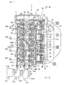
- an engine E is a water-cooled series 4-cylinder engine for a motorcycle, for example.
- a cylinder head 40 is fixed on the top face of a cylinder block 30, and a head cover 41 is mounted to the top face of the cylinder head 40.
- a cam chain case C is formed at a side portion of the engine E, #4 cylinder, #3 cylinder, #2 cylinder and #1 cylinder are arranged along the vehicle width direction from the side of the cam chain case C, and each of the cylinders is provided with two intake valves and two exhaust valves which will be described later.
- a throttle body 20 is connected to the cylinder head 40 substantially and horizontally.
- An intake duct 16 is connected on the upstream side of the throttle body 20, intake air passes through an intake passage 17, and is introduced to each cylinder via an intake port 18 in the cylinder head 40.
- a butterfly type throttle valve TH is provided in the intake passage 17 of the throttle body 20 in the state of being operable and closable between a fully opened position and a fully closed position.
- the throttle valve TH is of a so-called electronic throttle control system in which the throttle valve TH is opened and closed in conjunction with a motor 21 according to the grip opening (throttle operation variable) ⁇ g, i.e., the driver's intention toward acceleration or the like.
- a throttle valve opening sensor (throttle valve control mechanism) 22 for detecting the throttle valve opening is connected to the throttle valve TH so that the accurate turn angle of the throttle valve TH turned by the motor 21 can be detected.
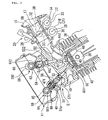
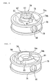
- a throttle body main body 200 is provided with four throttle valves TH, TH, TH, TH independent on the basis of each cylinder.
- the throttle body main body 200 is composed by interconnecting a third-fourth throttle body main body 200A corresponding to #4 cylinder and #3 cylinder, a second throttle body main body 200B corresponding to #2 cylinder, and a first throttle body main body 200C corresponding to #1 cylinder.
- #3 cylinder and #4 cylinder corresponding to the third-fourth throttle body main body 200A constitute a first cylinder group
- #2 cylinder corresponding to the second throttle body main body 200B constitutes a second cylinder group though it is a single cylinder
- #1 cylinder corresponding to the first throttle body main body 200C constitutes a third cylinder group though it is a single cylinder; thus, the engine is composed of the three cylinder groups.
- the throttle valve opening sensor 22 is coaxially mounted to the third-fourth throttle body main body 200A by small screws 24.
- a pulley 25 is mounted to an end portion, on the opposite side of the cam chain case C, of the third-fourth shaft 23.
- an injector 26 for injecting a fuel into each intake passage is inserted and fixed to an upper portion, or an upper wall, of the third-fourth throttle body main body 200A, inclinedly toward the cylinder head 40.
- the injector 26 is connected to a fuel supply pipe 27 (see FIG. 1 ).
- a third-fourth motor (throttle valve control mechanism) 21A is mounted to the third-fourth throttle body main body 200A on the opposite side of the injector 26 by a fastening means 29, with its drive shaft 28 set parallel to the third-fourth shaft 23.
- a pulley 31 is mounted to an end portion, on the opposite side of the cam chain case C, of the drive shaft 28 of the third-fourth motor 21A.
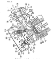
- a pulley 32 for opening and closing the throttle valve TH of the second throttle body main body 200B is mounted to an end portion on the opposite side of the cam chain case C.
- the throttle valve opening sensor 22 is mounted to a lower portion of the second throttle body main body 200B.
- a pulley 33 is mounted to an end portion, on the opposite side of the cam chain case C, of a sensor shaft 34 of the throttle valve opening sensor 22.
- a motor 21B is mounted to the front side of the throttle valve opening sensor 22 and on the opposite side of the injector 26 through a bracket (not shown), with its drive shaft set parallel to the shaft 35 of the throttle valve TH, and a pulley 36 is mounted to an end portion, on the opposite side of the cam chain case C, of a drive shaft of the motor 21B.
- a pulley groove 32M of the pulley 32 and a pulley groove of the pulley 36 of the motor 21B are connected by an endless wire 37, while a pulley groove 32 of the pulley 32 of the shaft 35 and a pulley groove of the pulley 33 of the throttle valve opening sensor 22 are connected by an endless wire 38.
- pulleys 32, 33, 36 are mounted to an end portion, on the opposite side of the cam chain case C, of the first throttle body main body 200C, and the throttle valve opening sensor 22 and the motor 21B in a font-rear relationship are mounted to a lower portion of the first throttle body main body 200C.
- the pulley 32 and the pulley 36 of the motor 21B are connected by an endless wire 37, while the pulley 32 and the pulley 33 of the throttle valve opening sensor 22 are connected by an endless wire 38.
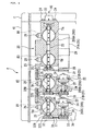
- the cylinder head 40 is provided with a recessed portion 43 for defining a combustion chamber 42 together with the cylinder block 30 and a piston 39, and the recessed portion 43 is provided with intake valve ports 441, 442 and exhaust valve ports 451, 452.
- the first intake valve port 441 is opened and closed by a first intake valve 461, and the second intake valve port 442 is opened and closed by a second intake valve 462.
- the first exhaust valve port 451 is opened and closed by a first exhaust valve 471, and the exhaust valve port 452 is opened and closed by a second exhaust valve 472.
- #4 cylinder as shown in FIGS.
- the first intake valve 461 is a restable intake valve
- the first exhaust valve 471 is a restable exhaust valve.
- the first intake valve 461 and the first exhaust valve 471 are disposed on a diagonal line
- the second intake valve 462 and the second exhaust valve 472 are disposed on a diagonal line.
- the first and second intake valves 461, 462 have a configuration in which the base end of a valve stem 49 is integrally connected to a valve body portion 48 capable of closing the corresponding intake valve port 441, 442, and the first and second exhaust valves 471, 472 have a configuration in which the base end of a valve stem 51 is integrally connected to a valve body portion 50 capable of closing the corresponding exhaust valve port 451, 452.
- valve stems 49 ⁇ of the first and second intake valves 461 and 462 are slidably fitted in guide cylinders 52 ⁇ provided in the cylinder head 40.
- valve stems 51 ⁇ of the first and second exhaust valves 471 and 472 are slidably fitted in guide cylinders 53 ⁇ provided in the cylinder head 40.
- a retainer 54 is fixed to a portion, projecting upward from the guide cylinder 52, of the valve stem 49 of the first intake valve 461, and the first intake valve 461 is biased in the direction of closing the first intake valve port 441 by a coil form valve spring 551 provided between the retainer 54 and the cylinder head 40.
- a retainer 54 is fixed to a portion, projecting upwards from the guide cylinder 52, of the valve stem 49 of the second intake valve 462, and the second intake valve 462 is biased in the direction of closing the second intake valve port 442 by a coil form valve spring 552 provided between the retainer 54 and the cylinder head 40.
- the first exhaust valve 471 is biased in the direction of closing the first exhaust valve port 451 by a coil form valve spring 571 provided between a retainer 56 fixed to the valve stem 51 of the first exhaust valve 471 and the cylinder head 40
- the second exhaust valve 472 is biased in the direction of closing the second exhaust valve port 452 by a coil form valve spring 572 provided between a retainer 56 fixed to the valve stem 51 of the second exhaust valve 472 and the cylinder head 40.
- the first and second intake valves 461 ⁇ , 462 ⁇ of the combustion chambers 42 ⁇ are driven by an intake-side valve operating device 58.
- the intake-side valve operating device 58 includes: a cam shaft 60 provided with first intake-side valve operating cams 591 ⁇ corresponding respectively to the first intake valves 461 ⁇ and second intake-side valve operating cams 592 ⁇ corresponding respectively to the second intake valves 462 ⁇ ; bottomed cylindrical valve lifters 611 ⁇ slid by being driven by the first intake-side valve operating cams 591 ⁇ ; and bottomed cylindrical valve lifters 612 slid by being driven by the second intake-side valve operating cams 592
- the cam shat 60 has an axis orthogonal to the extensions of the axes of the valve stems 49 ⁇ in the first and second intake valves 461 ⁇ , 462 ⁇ , and is rotatably supported between the cylinder head 40 and the head cover 41 joined to the cylinder head 40.
- the valve lifters 611 ⁇ are slidably fitted in the cylinder head 40 in the coaxial direction with the axes of the valve stems 49 ⁇ in the first intake valves 461 ⁇ , and the closing end outside surfaces of the valve lifters 611 ⁇ are in sliding contact with the first intake-side valve operating cams 591 ⁇ .
- valve lifter 612 ⁇ is slidably fitted in the cylinder head 40 in the coaxial direction with the axes of the valve stems 49 ⁇ in the second intake valves 462 ⁇ , and the closing end outside surfaces of the valve lifters 612 ⁇ are in sliding contact with the second intake-side valve operating cams 592 ⁇ .
- the stem ends of the valve stems 49 ⁇ in the second intake valve 462 are brought into contact with the closing end inside surface of the valve lifter 612 through a shim 62, and are normally opened and closed by the second intake-side valve operating cams 592 ⁇ during the operation of the engine E.
- a valve resting mechanism 63 which can change over between action and non-action of the pressing force in the valve-opening direction from the valve lifter 611 to the first intake valve 461 and which brings the first intake valve 461 into the rest state notwithstanding the sliding operation of the valve lifter 611 by bringing the pressing force into an inactive state in a specified operation range, for example, a low load range such as a low speed operation range of the engine E, is provided between the valve stems 49 ⁇ of the first intake valve 461 and the valve lifter 611.
- a specified operation range for example, a low load range such as a low speed operation range of the engine E
- the valve resting mechanism 63 includes a pin holder 74 slidably fitted in the vale lifter 611, a slide pin 76 slidably fitted in the pin holder 74 while forming an oil pressure chamber 75 between itself and the inside surface of the valve lifter 611, a return spring 77 provided between the slide pin 76 and the pin holder 74 while displaying a spring force for biasing the slide pin 76 in the direction of reducing the volume of the oil pressure chamber 75, and a stopper pin 78 provided between the pin holder 74 and the slide pin 76 while inhibiting the slide pin 76 from rotating about the axis thereof.
- a rest discrimination sensor 71 for detecting the position of the slide pin 76 is mounted on the side of the cylinder head 40.
- the pin holder 74 has a ring portion 74a slidably fitted in the valve lifter 611 (see FIG. 5 ), and an annular groove 79 is provided in the outer circumference of the ring portion 74a.
- a bridging portion 74b connecting between inner circumference portions of the ring portion 74a is integrally formed along one diameter of the ring portion 74a, and the portions between the inner circumference of the ring portion 74a and both side surfaces of the bridging portion 74b are lightened, for contriving a reduction in weight.
- Such a pin holder 74 is formed by lost wax casting or forging of iron or an aluminum alloy, or formed from a synthetic resin, and a cementation treatment is applied to the outer circumferential surface of the pin holder 74, i.e., the outer circumferential surface of the ring portion 74a, which is made of a metal, and to the inner circumferential surface of the valve lifter 611.
- the bridging portion 74b is provided with a slide hole 80 having an axis in the longitudinal direction of the bridging portion 74b, i.e., in a direction orthogonal to the axis of the valve lifter 611.
- the slide hole 80 has a bottomed shape, with one end being opened to the annular groove 79 and the other end being closed.
- the bridging portion 74b is provided in its central lower portion with an insertion hole 81 communicated with the slide hole 80.
- the bridging portion 74b is provided in its central upper portion with an extension hole 82 communicated with the slide hole 80, coaxially with the insertion hole 81.
- the bridging portion 74b is integrally provided, in the periphery of the extension hole 82, with a hollow cylindrical containing tube portion 83 coaxially with the axis of the extension hole 82. Further, the bridging portion 74b is provided in its upper portion with a mount hole 90 communicated with the slide hole 80, in the range from a portion corresponding to the one end (open end) of the slide hole 80 to the extension hole 82. Similarly, as shown in FIG. 5 , the bridging portion 74b is provided in its lower portion with a mount hole 89 communicated with the slide hole 80, in the range from a portion corresponding to the one end of the slide hole 80 to the insertion hole 81. The mount hole 89 is formed coaxially with the mount hole 90, and the stopper pin 78 is mounted therein.
- a disk-like shim 84 is fitted in the containing tube portion 83 of the pin holder 74, and an end portion of the extension hole 82 is thereby closed.
- a stem end 49a of the valve stem 49 of the first intake valve 461 is inserted in the insertion hole 81 in the lower portion of the pin holder 74.
- the slide pin 76 is slidably fitted in the slide hole 80.
- the oil pressure chamber 75 communicated with the annular groove 79 is formed between one end of the slide pin 76 and the inside surface of the valve lifter 611, and the return spring 77 is contained in a spring chamber 86 formed between the other end of the slide pin 76 and the closed end of the slide hole 80.
- the pin holder 74 is made of a synthetic resin, its portion for sliding contact with the slide pin 76 may only be made of a metal.
- the slide pin 76 is provided with a containing hole 87 in an intermediate portion in the axial direction thereof.
- the containing hole 87 is coaxially communicated with the insertion hole 81 and the extension hole 82, and has such a diameter that the stem end 49a of the valve stem 49 can be contained therein. Further, an end portion, on the side of the insertion hole 81, of the containing hole 87 is opened to a flat abutment surface 88 formed on the outside surface of a lower portion of the slide pin 76 oppositely to the insertion hole 81.
- the abutment surface 88 is formed to be comparatively long along the axial direction of the slide pin 76, and the containing hole 87 is opened to a portion, on the side of the spring chamber 86, of the abutment surface 88.
- a slit 91 opened to the side of the oil pressure chamber 75 is provided on one end side of the slid pin 76.
- a magnetism generating member such as a magnet is embedded in the slid pin 76 so as to enhance the detection accuracy of a rest discriminating magnetic sensor 71 which will be described later.
- the slid pin 76 is provided with a communication hole 96 for communicating the spring chamber 86 with the containing hole 87, for preventing variations in the pressure inside the spring chamber 86 from occurring when the slid pin 76 is moved in the axial direction.
- the pin holder 74 is provided with a communication hole 97 for communicating the space between the pin holder 74 and the valve lifter 611 with the spring chamber 86, for preventing the pressure in the space from varying with temperature.
- a wall portion 79a of the annular groove 79 forming the spring chamber 86 is provided with an opening 79b. The diameter of the opening 79b is set smaller than the diameter of the return spring 77.
- a coil spring 92 for biasing the pin holder 74 in the direction of abutting the shim 84 mounted to the pin holder 74 against the projected portion 85 of the valve lifter 611 is provided between the pin holder 74 and the cylinder head 40.
- the coil spring 92 is so mounted as to surround the valve stem 49 at such a position as to obviate the contact of its outer circumference with the inside surface of the valve lifter 611, and the bridging portion 74b of the pin holder 74 is integrally provided with a pair of projections 93, 94 for positioning an end portion of the coil spring 92 in a direction orthogonal to the axis of the valve stem 49.
- Both the projections 93, 94 are projectingly provided integrally on the pin holder 74 with a projection amount not more than the wire diameter of the coil spring 92, and is formed in a circular arc shape, with the axis of the valve stem 49 as a center of the circle.
- one 93 of the projections 93, 94 is provided with a step portion 95 which abuts on an end portion, on the side of the first intake valve 461, of the stopper pin 78 to thereby inhibit the stopper pin 78 from moving to the side of the first intake valve 461.
- the cylinder head 40 is provided with a support hole 98 for fitting the valve lifter 611 therein so as to slidably support the valve lifter 611, and the support hole 98 is provided in its inside surface with an annular recessed portion 99 for surrounding the valve lifter 611.
- the annular recessed portion 99 is connected to a working oil pressure supply passage 103 formed in the cylinder head 40, and is supplied with a working oil.
- the valve lifter 611 is provided with a release hole 101 and a communication hole 100 for communicating the annular recessed portion 99 with the annular groove 79 in the pin holder 74.
- the communication hole 100 is provided at such a position as to communicate the annular recessed portion 99 with the annular groove 79 notwithstanding the sliding of the valve lifter 611 in the support hole 98.
- the release hole 101 is provided in the valve lifter 611 at such a position that the annular recessed portion 99 is communicated with the inside of the valve lifter 611 on the lower side of the pin holder 74 when the valve lifter 611 is moved to an uppermost position as shown in FIG. 5 and that the communication with the annular recessed portion 99 is interrupted as the valve lifter 611 is moved downwards from the uppermost position as shown in FIG. 5 , and the working oil is jetted through the release hole 101 into the inside of the valve lifter 611 as a lubricating oil.
- the working oil supplied from the working oil pressure supply passage 103 into the annular groove 79 of the pin holder 74 through the communication hole 100 and the release hole 101 is supplied into the oil pressure chamber 75 via one end of the slide hole 80.
- the slide pin 76 is slid in the axial direction in such a manner that an oil pressure force acting on one end side of the slide pin 76 due to the oil pressure inside the oil pressure chamber 75 and a spring force acting on the other end side of the slide pin 76 due to the return spring 77 balance each other.
- the stem end 49a of the valve stem 49 inserted in the insertion hole 81 is moved to the right side in FIG.
- the rotation of the slide pin 76 about its axis is inhibited by the stopper pin 78.
- the stopper pin 78 pierces through the slit 91 of the slide pin 76.
- the stopper pin 78 is mounted to the pin holder 74 by piercing through the slide pin 76 while permitting the slide pin 76 to move in the axial direction, so that the abutment of the stopper pin 78 on an inner end closed portion of the slit 91 restricts the end of movement of the slide pin 76 to the side of the oil pressure chamber 75.
- the rest discriminating magnetic sensor 71 is mounted to the annular recessed portion 99 of the cylinder head 40 while fronting on the communication hole in the valve lifter 611 and on the opening 79b in the pin holder 76.
- the rest discriminating magnetic sensor 71 is a sensor which is for detecting the distance ds from the rest discriminating magnetic sensor 71 through the communication hole 100 and the opening 79b to a wall portion 76a of the slide pin 76, includes a magnet and a coil, and detects the distance ds by detecting a magnetic flux variation generated when the slide pin 76 made of a metal is moved.
- a cable 71a for outputting the detection results is connected to the rest discriminating magnetic sensor 71.
- the cable 71a is passed through an insertion hole formed in the cylinder head 40, and is connected to an ECU (cylinder number control unit) 70 (see FIG. 9 ) which will be described later.
- a rest discriminating sensor is not limited to the magnetic sensor; there may be used a sensor for detecting the distance ds by use of light, a sensor for detecting the distance ds by detecting a variation in electrostatic capacity, a sensor for detecting the distance ds by use of ultrasound, and the like.
- the exhaust-side valve operating device 68 has a camshaft 65 provided with a first exhaust-side valve operating cams 641 ⁇ corresponding respectively to the first exhaust valves 471 ⁇ and with second exhaust-side valve operating cams 642 ⁇ corresponding respectively to the second exhaust valves 472 ⁇ , and has bottomed hollow cylindrical valve lifters 661 ⁇ slid while being driven by the first exhaust-side valve operating cams 641 ⁇ and bottomed hollow cylindrical valve lifters 662 ⁇ slid while being driven by the second exhaust-side valve operating cams 642 ⁇ .
- the camshaft 65 has an axis orthogonal to the extensions of the axes of the valve stems 51 ⁇ of the first and second exhaust valves 471 ⁇ , 472 ⁇ , and is rotatably supported between the cylinder head 40 and the head cover 41 joined to the cylinder head 40, like the camshaft 60 of the intake-side valve operating device 58.
- the valve lifters 661 ⁇ are slidably fitted in the cylinder head 40 coaxially with the axes of the valve stems 51 ⁇ of the first exhaust valves 471 ⁇ , and the outside surfaces of the closed ends of the valve lifters 661 ⁇ are in sliding contact with the first exhaust-side valve operating cams 641 ⁇ .
- valve lifters 662 ⁇ are slidably fitted in the cylinder head 40 coaxially with the axes of the valve stems 51 ⁇ of the second exhaust valves 472 ⁇ , and the outside surfaces of the closed ends of the valve lifters 662 ⁇ are in sliding contact with the second exhaust-side valve operating cams 642 ⁇ .
- valve stem 51 ⁇ of the second exhaust valve 472 abuts on the inside surface of the closed end of the valve lifter 662 through the shim 67, and are normally opened and closed by the second exhaust-side valve operating cam 642 ⁇ during the operation of the engine E.
- a valve resting mechanism 69 which can change over the action and non-action of the pressing force exerted from the valve lifter 661 on the first exhaust valve 471 in the valve-opening direction and which brings the first exhaust valve 471 into a resting state irrespectively of the sliding of the valve lifter 661 by putting the pressing force into an inactive state in a specified operation range of the engine E, for example, in a low load range such as a low speed operation range, is provided between the stem ends 51a of the valve stem 51 ⁇ of the first exhaust valve 471 and the valve lifter 661.
- the valve resting mechanism 69 of the exhaust-side valve operating device 68 is configured in the same manner as the valve resting mechanism 63 (see FIG. 5 ) in the intake-side valve operating device 58.
- valve resting mechanism 63 and the valve resting mechanism 69 configured in the same manner as in #4 cylinder are provided for the second exhaust valve 472 (corresponding to a second exhaust valve port 452) and the second intake valve 462 (corresponding to a second intake valve port 442), in the manner contrary to that in #4 cylinder. Further, in #1 cylinder and #2 cylinder, the valve resting mechanism 63 and the valve resting mechanism 69 are provided for all the intake valves 461, 462 and the exhaust valves 471, 472.
- valve resting mechanisms 63, 69 are provided for all the engine valves, these valve resting mechanisms 63, 69 function as a cylinder resting mechanism, and a cylinder rest where all the engine valves are in rest (the cylinders are restable cylinders) can be performed.
- a valve rest where one engine valve each on the intake side and the exhaust side is in rest (the cylinders are normally operative cylinders) can be performed.
- a side wall on the #4 cylinder side of the cylinder head 40 is provided with a cam chain case C, and a cam chain (not shown) for driving the camshafts 60, 65 of the intake-side and exhaust-side valve operating devices 58, 68 are contained in the cam chain case C.
- a side wall of the cylinder head 40 on the opposite side of the cam chain case C is provided with connection ports PA, PB, PC of oil pressure control valves (variable valve number control mechanisms) 113A, 113B, 113C for controlling the supply of the working oil to the valve resting mechanisms 63 ⁇ , 69 ⁇ (see FIGS. 2 and 3 ) of the intake-side and exhaust-side valve operating devices 58, 68.
- connection port PA is connected to a working oil supply passage 103A which is extended in the cylinder head 40 between a central portion in the front-rear direction of the cylinder head 40 to each intake valve port along the longitudinal direction to the layout position of the second intake valve port 442 of #2 cylinder and which is branched toward the second intake valve port 442 of #2 cylinder and the second exhaust valve port 452 of #2 cylinder.
- connection port PB is connected to a working oil supply passage 103B which is extended in the cylinder head 40 between a central portion in the front-rear direction of the cylinder head 40 to each exhaust valve port along the longitudinal direction to the layout position of the first exhaust valve port 451 of #1 cylinder and which is branched toward the first exhaust valve port 451 of #1 cylinder and the first intake valve port 441 of #1 cylinder.
- connection port PC is connected to a working oil supply passage 103C which is extended in the other side wall of the cylinder head 40 along the longitudinal direction to the layout position of the first exhaust valve port 451 of #4 cylinder and which is branched toward the first exhaust valve port 451 of #4 cylinder, the second exhaust valve port 452 of #3 cylinder, the first exhaust valve port 451 of #2 cylinder and the second exhaust valve port 452 of #1 cylinder.
- a working oil supply passage 103C' is formed in the rear side wall of the cylinder head 40 along the longitudinal direction of the cylinder head 40 to the layout position of the first intake valve port 441 of #4 cylinder, and the working oil supply passage 103C and the working oil supply passage 103C' are connected to each other through a crossing passage 103X.
- the working oil supply passage 103C' is branched to be connected to the first intake valve port 441 of #4 cylinder, the second intake valve port 442 of #3 cylinder, the first intake valve port 441 of #2 cylinder and the second intake valve port 442 of #1 cylinder.
- #1 cylinder and #2 cylinder among #1 cylinder, #2 cylinder and #3 cylinder i.e., the cylinders located on the opposite side of the cam chain case C, all the engine valves consisting of the first intake valve 461, the second intake valve 462, the first exhaust valve 471 and the second exhaust valve 472 are configured to be restable.
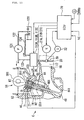
- the oil pressure control valves 113A, 113B, 113C are supplied with the working oil which is reserved in an oil pan 120.
- a main oil pressure passage 122 fitted with a pump 121 is connected to the oil pan 120, and, on the discharge side of the pump 121, a branch passage 123 connected to the oil pressure control valves 113A, 113B, 113C is branched from the main oil pressure passage 122.
- the drain ports D (see FIG. 1 ) of the oil pressure control valves 113A, 113B, 113C are connected to a drain passage 124 so that the working oil can be recovered into the oil pan 120.
- the control of the oil pressure control valves 113A, 113B, 113C is conducted by the ECU 70, which is an electronic control unit, based on the grip opening (throttle operation variable) ⁇ g detected by a grip opening sensor G, the engine speed Ne, the rest discriminating magnetic sensor 71 and the like.
- the ECU 70 controls the throttle valve TH by outputting a turning command signal to each of the motors 21A, 21B while detecting the throttle valve opening by a throttle valve opening sensor 22 so as to set optimum the throttle valve opening based on the value detected by the grip opening sensor G and the like.
- fuel injection amount at the injector 26 is regulated based on a control signal from the ECU 70.
- the ECU 70 has means for changing over the oil pressure control valves 113A, 113B, 113C, means for controlling the throttle valve opening, and means for controlling the fuel injection amount.
- the valve rest and the cylinder rest conducted under the control by the ECU 70 will be described, the description being centered on the operations of the intake valves 461, 462 and the exhaust valves 471, 472 provided with the valve resting mechanisms 63, 69.
- the ECU 70 drives the throttle valve TH by outputting the turning command signal to each of the motors 21A, 21B while detecting the throttle valve opening by the throttle valve opening sensor 22, based on the detection signals fed from the grip opening sensor G and the like.
- the fuel injection amount at the injector 26 is regulated based on the control signal from the ECU 70.
- the oil pressure chamber 75 of the valve resting mechanism 63 is supplied with the working oil via the working oil supply passage 103, whereby the return spring 77 is compressed, and the slide pin 76 is located on a comparatively left side in FIG. 9 .
- the valve resting mechanism 69 on the exhaust side as shown in FIG. 2 is also configured so that the oil pressure of the working oil acts on the slide pin 76.
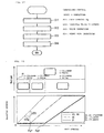
- the processing by the ECU 70 in the case where predetermined conditions are fulfilled and the valve rest and cylinder rest are conducted will be described based on a flow chart shown in FIG. 10 .
- the ECU 70 detects the grip opening ⁇ g (step S1), and the passage of current to the injector 26 is stopped, thereby stopping the fuel supply (F1) (step S2). Thereafter, the exhaust valves 471, 472 and the intake valves 461, 462 are rested (step S3).
- the resting of the exhaust valves 471, 472 and the intake valves 461, 462 is carried out as follows. After the completion of the exhaust stroke is confirmed by a crank angle sensor (not shown) or the like, a control signal is outputted to each of the oil pressure control valves 113A, 113B, 113C, to discharge the working oil from the oil pressure chamber 75 (see FIG. 5 ), and the exhaust valves 471, 472 are rested. The resting of the exhaust valves 471, 472 is confirmed by use of the rest discriminating magnetic sensor 71.
- the ECU 70 judges that the exhaust valves 471, 472 corresponding to the rest discriminating magnetic sensor 71 has come to a rest.
- a control signal is outputted to each of the oil pressure control valves 113A, 113B, 113C, to stop the intake valves 461, 462.
- the resting of the intake valves 461, 462 is also conducted based on the distance ds detected by the rest discriminating magnetic sensor 71 provided in the vicinity of the stem end 49a of each of the intake valves 461, 462, in the same manner as above.
- the throttle valve TH is put into a closed state by driving the motors 21A, 21B (step S4), and the supply of electric power to the spark plug is interrupted (step S5).
- the cutoff of ignition is carried out several cycles (in this embodiment, 10 cycles), and thereafter the ignition is reset.
- the working oil is discharged via the drain passage 124 as shown in FIG. 11 , the slide pin 76 is moved by the force of the return spring 77 so as to reduce the oil pressure chamber 75, and the containing hole 87 is matched to the insertion hole 81 in the pin holder 74.
- the stem end 49a (see FIG. 5 ) of the valve stem 49 is only contained into the insertion hole 81 and the containing hole 87, and no pressing force is exerted on the first intake valve 461, so that the first intake valve port 441 is kept closed.
- the working oil is similarly discharged also from the valve resting mechanism 69 on the exhaust side as shown in FIG. 3 , the containing hole 87 is' matched to the insertion hole 81 in the pin holder 74, and no pressing force is exerted on the first exhaust valve 471, so that the first exhaust valve port 451 is kept closed.
- the ECU 70 detects the grip opening ⁇ g (step S11), and brings the throttle valve TH into an open state by driving the motors 21A, 21B while detecting the throttle valve opening by the throttle valve opening sensor 22, based on the grip opening ⁇ g (step S12). Then, the intake valves 461, 462 and the exhaust valves 471, 472 are operated (step S13). The operations of the exhaust valves 471, 472 and the intake valves 461, 462 are conducted as follows.
- a control signal is outputted to each of the oil pressure control valves 113A, 113B, 113C, whereby an oil pressure is exerted on the slide pin 76 to move the slide pin 76, to operate the first exhaust valve 471.
- the operations of the exhaust valves 471, 472 are confirmed by use of the rest discriminating magnetic sensor 71.
- the ECU 70 judges that the exhaust valve 471, 472 corresponding to the rest discriminating magnetic sensor 71 has changed over to an operative state.
- a control signal is outputted from the ECU 70 to each of the oil pressure control valves 113A, 113B, 113C (see FIG. 1 ), whereby the intake valves 461, 462 are operated.
- the operations of the intake valves 461, 462 are confirmed based on the distance ds detected by the rest discriminating magnetic sensor 71, in the same manner as above.
- the injector 16 is operated, to start the fuel supply (step S14). Incidentally, in this instance, the cutoff of ignition has been reset, so that the engine is driven by starting the fuel supply.
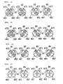
- the engine valves (the exhaust valves 471, 472 and the intake valves 461, 462) are operated according to the grip opening ⁇ g and how the throttle valve TH is opened to increase the engine output will be described, based on FIGS. 14 to 16 .
- the hatched valves are the engine valves in the resting state.
- the intake valves 461, 462 and the exhaust valves 471, 472 which are the engine valves are all rested (all valve rest), the cylinder rest results.
- first intake valve 461 and the first exhaust valve 472 are disposed on a diagonal line
- second intake valve 462 and the second exhaust valve 472 are disposed on a diagonal line
- adjacent exhaust valves 471, 472 of the two adjacent cylinders are configured as operative cylinders
- a secondary air introduction valve AI is provided between the exhaust valves 471, 472.
- the cylinders to be operated and the throttle valve opening in each cylinder group are determined uniquely, on the basis of the grip opening ⁇ g best representing the driver's intention to accelerate. Specifically, the number of the cylinder groups to be operated is increased with an increase in at least the grip opening ⁇ g. In addition, whether the cylinder is to be rested or operated is determined based on whether the engine speed Ne is higher or lower than a threshold. These are controlled by the ECU 70.
- a threshold value ⁇ (valve changeover engine speed)
- 2-valve operation for a low load time is established in which the individual cylinder groups, here, the cylinder group composed of #3 cylinder and #4 cylinder, the cylinder group composed of #2 cylinder (in this embodiment, a single cylinder), and the cylinder group composed of #1 cylinder (in this embodiment, a single cylinder) are each operated by use of single intake and exhaust valves.
- the cylinder rest (all valve rest) is conducted in #1 cylinder and #2 cylinder, the valve rest is conducted in #3 cylinder and #4 cylinder, and, in this condition, the throttle valve opening is gradually increased with an increase in the grip opening ⁇ g.
- the throttle valve TH for #3 cylinder and #4 cylinder is gradually opened (2-cylinder 2-valve operation shown in FIG. 13 ).
- the average of an increase ratio (dTH/d ⁇ g) of the throttle valve opening to the grip opening in #3 cylinder and #4 cylinder is set higher than the average of the increase ratio of the throttle valve opening to the grip opening in #2 cylinder.
- valve rest is conducted in all cylinders from #1 cylinder to #4 cylinder, and, in this condition, the throttle valve TH of #1 cylinder is started to open, in addition to #3 cylinder, #4 cylinder, and #2 cylinder in which the throttle valve thereafter increases continuedly.
- the throttle valve TH in #1 cylinder, in addition to #3 cylinder and #4 cylinder is gradually opened (4-cylinder 2-valve operation shown in FIG. 13 ). Therefore, the throttle valve openings in #3 cylinder and #4 cylinder, in #2 cylinder, and in #1 cylinder are different, except for the fully opened time and the fully closed time of the throttle valve TH.
- the throttle valve openings in #3 cylinder and #4 cylinder, in #2 cylinder, and in #1 cylinder are different, except for the fully opened time and the fully closed time of the throttle valve TH, and the throttle valve TH in the next cylinder group is opened before the throttle valve opening in the former cylinder group reaches the fully opened state. Therefore, as compared to the case where the throttle valves in all cylinder groups are simultaneously opened to thereby increase the output, the engine E can be operated with high combustion efficiency, which can contribute to improvement of fuel consumption.
- the throttle valve in the next cylinder group is opened before the throttle valve opening in the former cylinder group reaches the fully opened state, it is possible to eliminate the step in output, and to realize a smooth operation.
- the average of the increase ratio (dTH/d ⁇ g) of the throttle valve opening to the grip opening in #3 cylinder and #4 cylinder whose throttle valves are opened first is set higher than the average of the increase ratio of the throttle valve opening to the grip opening in #2 cylinder whose throttle opening is next started to open. Further, the average of the increase ratio of the throttle valve opening to the grip opening in #2 cylinder is set higher than that in #1 cylinder whose throttle valve is next started to open. In other words, the increase ratio in a cylinder whose throttle valve is opened first at the time of starting the grip operation is set to be high, and the increase ratios in the cylinders whose throttle valves are thereafter opened sequentially are set to be gradually lowered. Referring to FIG. 13 , the inclinations of the three lines are so set that the inclination is greater as the line is located on the more left side.
- the increase ratio is high in a low load range, by bringing the throttle valve opening to the fully opened state earlier, it is possible to operate in the range with a higher load factor, and to reduce the pumping loss, so that an improvement in fuel consumption can be contrived.
- the intake air amount at a low load time it is possible to enhance the flow rate of the intake air, and to enhance the combustion efficiency.
- by resting a specified valve or valves it is possible to generate an intake air swirl. As a result, the fuel consumption can be further improved.
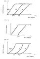
- FIG. 18 shows a second embodiment of the present invention, in which the throttle valve opening in relation to the grip opening is different in #3 cylinder and #4 cylinder, in #2 cylinder, and in #1 cylinder, as shown in FIG. 13 .
- the throttle valve openings set for #3 cylinder and #4 cylinder, for #2 cylinder, and for #1 cylinder are so set that the increase factor is gradually enlarged according to the grip opening ⁇ g in the vicinity of the full closure of the throttle valve and that the increase factor is gradually reduced according to the grip opening ⁇ g in the vicinity of the full opening of the throttle valve.
- FIG. 18 shows a second embodiment of the present invention, in which the throttle valve opening in relation to the grip opening is different in #3 cylinder and #4 cylinder, in #2 cylinder, and in #1 cylinder, as shown in FIG. 13 .
- the throttle valve openings set for #3 cylinder and #4 cylinder, for #2 cylinder, and for #1 cylinder are so set that the increase factor is gradually enlarged according to the grip opening ⁇ g in the vicinity of the full closure of the throttle valve
- the throttle valve openings in #3 cylinder and #4 cylinder, in #2 cylinder, and in #1 cylinder are so set that the increase ratio (rise-up) is gradually reduced in the vicinity of the full opening position
- the throttle valve openings in #2 cylinder and #1 cylinder are so set that the increase ratio (rise-up) is gradually enlarged in the vicinity of the full closure position.
- the increase ratio of the throttle valve opening is gradually reduced in the vicinity of the full opening of the throttle valve for #3 cylinder and #4 cylinder, and the increase ratio of the throttle valve opening is enlarged at the start of opening of the throttle valve for #2 cylinder, whereby the process in which the throttle valve opening for #3 cylinder and #4 cylinder is gradually brought to the fully opened state can be compensated for by the rise-up at the start of opening of the throttle valve for #2 cylinder; therefore, it is possible to reduce the output variation at the time of starting the operation of #2 cylinder, to contrive an enhanced sense of power, and to enhance drivability.
- the increase ratio of the throttle valve opening is gradually reduced in the vicinity of the full opening of the throttle valve for #2 cylinder, and the increase ratio of the throttle valve opening is enlarged at the start of opening of the throttle valve for #1 cylinder, whereby the process in which the throttle valve opening of #2 cylinder is gradually brought to the fully opened state can be compensated for by the rise-up at the start of opening of the throttle valve of #1 cylinder. Therefore, it is possible to reduce the output variation at the time of starting the operation of #1 cylinder, to contrive an enhanced sense of power, and to enhance drivability.
- FIG. 19 shows a third embodiment of the present invention, in which the openings at the start of opening of the throttle valves TH for #2 cylinder and #1 cylinder in the first embodiment shown in FIG. 13 are set to a predetermined opening (for example, 5°).
- FIG. 19 shows an example of #2 cylinder.
- the third embodiment it is possible to suppress the lowering in output due to the pumping loss which would be generated at the time of opening of the throttle valve TH of #2 cylinder being in the fully closed state during operation of #2 cylinder. Therefore, it is possible to eliminate the dropping in output when #2 cylinder is operated, and to secure a smooth rise-up.
- this embodiment is applicable also to the second embodiment.
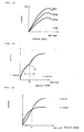
- FIGS. 20 and 21 show a fourth embodiment of the present invention.
- the increase ratio of the throttle valve opening to the grip opening is increased from the full closure to the full opening of the throttle valve.
- rise-up lines for #3 cylinder and #4 cylinder, for #2 cylinder, and for #1 cylinder are so set that the degree of rise-up is steeper for the latter period near the end of rise-up.
- the output (PS) characteristic against the engine speed Ne in an arbitrary cylinder is set according to the throttle valve opening; however, a characteristic near that at a full opening time (wholly opened time) (WOT) is displayed even when the throttle valve opening is 50% based on that at the full opening time (WOT). Therefore, even if the output is reduced from that at the full opening time (WOT) to 50% thereof, the output is not lowered by a corresponding degree. Therefore, it is impossible to obtain an output characteristic which is linear in relation to the grip opening determining the throttle valve opening, i.e., in relation to the driver's intention to operate the engine. In other words, as the throttle valve is gradually opened, a certain degree of rise-up in output can be obtained in the beginning period of the opening operation, but it becomes impossible to obtain a satisfactory rise-up in output in the ending period of the opening operation.
- the rise-up in output (the increase ratio) is suppressed in the beginning period of operation when the rise-up of output is large, and the rise-up of output is set greater in the latter period near the end of the operation of the grip. Therefore, the variation in output characteristic with grip opening is made linear, and drivability can be enhanced. Accordingly, the output is increased, without a sense of incompatibility, according to the grip opening which shows the driver's intention to accelerate, and a pleasant operation can be realized.
- FIGS. 22 to 24 show a fifth embodiment of the present invention.
- whether the valve is to be rested or operated is determined depending on whether the engine speed Ne is higher or lower than a threshold value ⁇ ; a 2-valve operation is conducted when the engine speed Ne is lower than the threshold value ⁇ , and a 4-valve operation is conducted when the engine speed Ne is not less than the threshold value ⁇ .
- the characteristic of output against engine speed Ne is different between the 2-valve operation and the 4-valve operation.
- a discontinuity point P having a drop in output is generated at the position of the threshold value ⁇ of the engine speed Ne which is an intersection portion of both characteristics, in the characteristic of output against engine speed Ne.
- the actual throttle valve opening is increased over the range from a point immediately before the threshold value ⁇ of the engine speed at the time of changeover of operation to a point immediately after the threshold value ⁇ .
- the present invention is not limited to the above-described embodiments; while description has been made taking a motorcycle as an example, the invention is applicable also to four-wheeled vehicles. In that case, the acceleration pedal opening can be used in place of the grip opening.
- the invention is applicable also to an engine in which each cylinder is provided with one intake valve and one exhaust valve.
- the invention is applicable to not only the 4-cylinder engine but also to a 6-cylinder engine, and the combination of cylinders and the number of cylinder groups can be freely set; for example, three of the six cylinders constitute a cylinder group, two of the cylinders constitute another cylinder group, and the remaining one of the cylinders singly constitutes a cylinder group.
- the above-mentioned valve resting mechanism is a mere example, and a valve resting mechanism of the type in which valve rest is achieved by use of a rocker arm can be adopted. Besides, all cylinders may be put into all valve rest.
- valve resting mechanism (cylinder resting mechanism)
- 70 ECU (throttle valve control unit) 113A, 113B, 113C: oil pressure control valve (variable valve number control mechanism)
- ⁇ threshold value (valve changeover engine speed)
- TH throttle valve
- ⁇ g grip opening (throttle operation variable)
- dTH/d ⁇ g increase ratio
Landscapes
- Engineering & Computer Science (AREA)
- Mechanical Engineering (AREA)
- General Engineering & Computer Science (AREA)
- Chemical & Material Sciences (AREA)
- Combustion & Propulsion (AREA)
- Output Control And Ontrol Of Special Type Engine (AREA)
- Valve Device For Special Equipments (AREA)
- Electrical Control Of Air Or Fuel Supplied To Internal-Combustion Engine (AREA)
- Combined Controls Of Internal Combustion Engines (AREA)
- Control Of Throttle Valves Provided In The Intake System Or In The Exhaust System (AREA)
Description
- The present invention relates to a cylinder rest inenal combustion engine with some of a plurality of cylinders being restable.
- Among multiple-cylinder internal combustion engines, there is one in which some of the cylinders are restable. For example, a plurality of cylinders are divided into at least two groups, the throttle valve opening of the other group is set smaller than that of a first group in a low load range where the throttle valve opening of the first group is less than a predetermined value, and throttle valve control means is provided for ensuring that, when the throttle valve opening of the first group has reached the predetermined value, the throttle valve opening of the other group is thereafter increased at a ratio larger than that for the throttle valve opening of the first group. When the throttle valve opening of the other group has coincided with the throttle valve opening of the first group, the throttle valve openings of the first and other groups are thereafter varied at the same rate (see
Patent Document Japanese Patent Laid-open No. Hei 07-150982 - In the above-mentioned related art, the irregular combustion in a 2-cycle engine can be suppressed by the throttle valve control; but, since the cylinders in the other group which have been rested are operated when the throttle valve opening in the first group has reached a predetermined value, a step in output would be generated at the time of operating the cylinders in the other group.
The purpose ofJP 58035244 - Accordingly, it is an object of the present invention to provide a cylinder rest internal combustion engine which can eliminate the output variations at the time of variations in the number of cylinder.
- In order to attain the above object, the invention according to
claim 1 resides in a cylinder rest internal combustion engine including a plurality of cylinders divided into two or more groups, at least some of the cylinders being restable through a cylinder resting mechanism (for example, thevalve resting mechanism 63 and thevalve resting mechanism 69 in the embodiment), a throttle valve (for example, the throttle valve TH in the embodiment) of each of the cylinders being operable independently on the basis of the group to which the cylinder belongs, and the number of resting cylinders being controlled according to a throttle operation variable (for example, the grip opening θg in the embodiment) set by the driver. The throttle valve opening is different between the groups, except for the fully opened time and the fully closed time of the throttle valve, and a throttle valve control unit (for example, theECU 70 in the embodiment) for opening the throttle valve in the next cylinder group before the throttle valve opening of the former cylinder group is brought to a fully opened state.
With such a configuration, the throttle valve of the next cylinder group is opened before the throttle valve opening of the former cylinder group reaches a fully opened state, whereby the internal combustion engine can be operated with a better combustion efficiency, as compared to the case where the output is increased by simultaneously opening the throttle valves of all the cylinder groups. Among others, it is possible to eliminate steps in output, since the throttle valve of the next cylinder group is opened before the throttle valve opening of the former cylinder group reaches the full opening. - The invention is characterized in that the average of the increase ratio of the throttle valve opening to the throttle operation variable in each of the cylinder groups is set higher for the cylinder group whose throttle valve is opened first upon the start of throttle operation, and the average is set to be gradually lower for the cylinder groups whose throttle valves are thereafter opened sequentially.
With such a configuration, by bringing the throttle valve opening to the full opening early in a low load range, it is possible to operate with the load factor in a higher range. In addition, it is possible to reduce the pumping loss. - The invention according to
claim 2 is characterized in that the plurality of cylinders include normally operative cylinders (for example, #4 cylinder and #3 cylinder in the embodiment) and restable cylinders (for example, #2 cylinder and #1 cylinder in the embodiment), and the opening at the start of opening of the throttle valve in the restable cylinder is set to a predetermined opening. With such a configuration, it is possible to suppress the lowering in output due to the pumping loss generated at the time of opening a fully closed throttle valve when a resting cylinder is operated. - The invention according to
claim 3 is characterized in that the throttle valve opening set for each of the cylinder groups is so set that the increase ratio (for example, the increase ratio dTH/dθg in the embodiment) is gradually enlarged according to the throttle operation variable in the vicinity of the full closure of the throttle valve, and the increase ratio is gradually reduced according to the throttle operation variable in the vicinity of the full opening of the throttle valve. With such a configuration, by a method in which the increase ratio of the throttle valve opening is gradually reduced in the vicinity of the full opening of the throttle valve of the former cylinder group and the increase ratio of the throttle valve opening is enlarged at the start of opening of the throttle valve of the next cylinder group, the process in which the throttle valve opening of the former group is gradually brought to the fully opened state can be compensated for by the rise at the start of opening of the throttle valve of the next cylinder group. - The invention according to
claim 4 is characterized in that a variable valve number control mechanism (for example, mainly, the oilpressure control valves - With such a configuration, by reducing the number of operative valves for limiting the intake air quantity at a low load time, it is possible to enhance the flow rate of the intake air. In addition, by resting the specified valve or valves, it is possible to generate an intake air swirl.
- The invention according to
claim 5 is characterized in that, in the case of changing over the number of operative valves by the variable valve number control mechanism, the throttle valve opening is increased before a valve changeover revolution number (for example, the threshold value α of engine speed in the embodiment).
With such a configuration, it is possible to suppress the torque variations at the time of a changeover of the number of valves, and to achieve a linear output characteristic. - The invention according to claim 6 is characterized in that the increase ratio of the throttle valve opening to the throttle operation variable is increased from the full closure of the throttle valve to the fully opening of the throttle valve.
With such a configuration, by increasing the increase ratio of the throttle valve opening to the throttle operation variable from the full closure to the full opening, it is possible to eliminate or suppress the sense of incompatibility which would be generated by the saturation of output characteristic even upon an increase in the throttle operation variable, and to make linear the variation in output characteristic with the throttle operation variable. - According to the invention according to
claim 1, the throttle valve of the next cylinder group is opened before the throttle valve opening of the former cylinder group reaches the full opening, whereby the internal combustion engine can be operated with a better combustion efficiency, with the result of contribution to an improvement in fuel consumption, as compared with the case where the output is increased by simultaneously opening the throttle valves of all the cylinder groups. Among others, since the throttle valve of the next cylinder group is opened before the throttle valve opening of the former cylinder group reaches the full opening, it is possible to eliminates the steps in output, and therefore to realize a smooth operation. - By early bringing the throttle valve opening to the full opening in a low load range, it is possible to operate the engine with the load factor in a higher range, to reduce the pumping loss, and thereby to contrive an improvement in fuel consumption.
- According to the invention according to
claim 2, it is possible to suppress the lowering in output due to the pumping loss which would be generated at the time of opening a fully closed throttle valve in operating a resting cylinder, so that it is possible to eliminate a dropping in output at the time of operating a resting cylinder, and to secure a smooth rise-up in output. - According to the invention according to
claim 3, the increase ratio of the throttle valve opening is gradually reduced in the vicinity of the full opening of the throttle valve of the former cylinder group, and the increase ratio of the throttle valve opening is enlarged at the start of opening of the throttle valve of the next cylinder group, whereby the process in which the throttle valve opening of the former cylinder group is gradually brought to the fully opened state can be compensated for by the rise-up at the start of opening of the throttle valve of the next cylinder group. Therefore, it is possible to reduce the output variation at the start of operation of the next cylinder group, to contrive an enhanced sense of power, and to enhance the drivability. - According to the invention according to
claim 4, by reducing the number of operative valves for limiting the intake air quantity at a low load time, it is possible to enhance the flow rate of the intake air, and thereby to enhance the combustion efficiency. In addition, an intake air swirl can be generated by resting a specified valve or valves, so that it is possible to further enhance the combustion efficiency. - According to the invention according to
claim 5, it is possible to suppress the torque variation at the time of changeover of the number of valves, to make linear the output characteristic, and to enhance the drivability. - According to the invention according to claim 6, by increasing the increase ratio of throttle valve opening to throttle valve variable from the full closure to the full opening, it is possible to eliminate or reduce the sense of incompatibility generated due to saturation of output characteristic notwithstanding an increase in the throttle operation variable, and to make linear the variation in output characteristic with the throttle operation variable, so that the drivability is enhanced.
-
FIG. 1 is a plan view of a major part in one embodiment of the present invention. -
FIG. 2 is a sectional view along line 2-2 ofFIG. 1 . -
FIG. 3 is a sectional view along line 3-3 ofFIG. 1 . -
FIG. 4 is a sectional view along line 4-4 ofFIG. 1 . -
FIG. 5 is a partially enlarged sectional view ofFIG. 2 . -
FIG. 6 is a perspective view, as viewed from the upper side, of a pin holder. -
FIG. 7 is a perspective view, as viewed from the lower side, of the pin holder. -
FIG. 8 is a perspective view of a slide pin. -
FIG. 9 is a system diagram showing a valve operating condition. -
FIG. 10 is a flow chart showing the processings from valve operation to valve rest. -
FIG. 11 is a system diagram showing a valve rest condition. -
FIG. 12 is a flow chart showing the processings from valve rest to valve operation. -
FIG. 13 is a graph diagram showing the relationships of throttle valve opening and engine speed with grip opening. -
FIG. 14 is an illustration of the valve condition where the grip opening is in the range of 0 to θg2. -
FIG. 15 is an illustration of the valve condition where the grip opening is in the range of θg2 to θg1. -
FIG. 16 is an illustration of the valve condition where the grip opening is not less than θg2. -
FIG. 17 is an illustration of the valve condition -
FIG. 18 is a graph diagram showing the relationship between grip opening and throttle valve opening in a second embodiment. -
FIG. 19 is a graph diagram showing partly the relationship between grip opening and throttle valve opening in a third embodiment. -
FIG. 20 is a graph diagram showing the relationship between grip opening and throttle valve opening in a fourth embodiment. -
FIG. 21 is a graph diagram showing the relationship between engine speed and output. -
FIG. 22 is a graph diagram showing the relationship between engine speed and output in a fifth embodiment. -
FIG. 23 is a graph diagram showing the relationships between engine speed and output, in 2-valve operation and in 4-valve operation. -
FIG. 24 is a graph diagram showing the relationship between engine speed and throttle opening correction coefficient. - As shown in
FIGS. 1 to 3 , an engine E is a water-cooled series 4-cylinder engine for a motorcycle, for example. In the engine E, acylinder head 40 is fixed on the top face of acylinder block 30, and ahead cover 41 is mounted to the top face of thecylinder head 40.
A cam chain case C is formed at a side portion of the engine E, #4 cylinder, #3 cylinder, #2 cylinder and #1 cylinder are arranged along the vehicle width direction from the side of the cam chain case C, and each of the cylinders is provided with two intake valves and two exhaust valves which will be described later. - As shown in
FIGS. 2 and3 , athrottle body 20 is connected to thecylinder head 40 substantially and horizontally. Anintake duct 16 is connected on the upstream side of thethrottle body 20, intake air passes through anintake passage 17, and is introduced to each cylinder via anintake port 18 in thecylinder head 40. - A butterfly type throttle valve TH is provided in the
intake passage 17 of thethrottle body 20 in the state of being operable and closable between a fully opened position and a fully closed position. The throttle valve TH is of a so-called electronic throttle control system in which the throttle valve TH is opened and closed in conjunction with amotor 21 according to the grip opening (throttle operation variable) θg, i.e., the driver's intention toward acceleration or the like. In addition, a throttle valve opening sensor (throttle valve control mechanism) 22 for detecting the throttle valve opening is connected to the throttle valve TH so that the accurate turn angle of the throttle valve TH turned by themotor 21 can be detected. - As shown in
FIG. 4 , in thethrottle body 20, a throttle bodymain body 200 is provided with four throttle valves TH, TH, TH, TH independent on the basis of each cylinder. The throttle bodymain body 200 is composed by interconnecting a third-fourth throttle bodymain body 200A corresponding to #4 cylinder and #3 cylinder, a second throttle bodymain body 200B corresponding to #2 cylinder, and a first throttle bodymain body 200C corresponding to #1 cylinder.
Therefore, #3 cylinder and #4 cylinder corresponding to the third-fourth throttle bodymain body 200A constitute a first cylinder group, #2 cylinder corresponding to the second throttle bodymain body 200B constitutes a second cylinder group though it is a single cylinder, and #1 cylinder corresponding to the first throttle bodymain body 200C constitutes a third cylinder group though it is a single cylinder; thus, the engine is composed of the three cylinder groups. - At an end portion, on the side of the cam chain case C, of a third-
fourth shaft 23 which is a valve shaft, the throttlevalve opening sensor 22 is coaxially mounted to the third-fourth throttle bodymain body 200A bysmall screws 24. In addition, apulley 25 is mounted to an end portion, on the opposite side of the cam chain case C, of the third-fourth shaft 23. On the other hand, aninjector 26 for injecting a fuel into each intake passage (seeFIG. 2 ) is inserted and fixed to an upper portion, or an upper wall, of the third-fourth throttle bodymain body 200A, inclinedly toward thecylinder head 40. - The
injector 26 is connected to a fuel supply pipe 27 (seeFIG. 1 ). In addition, a third-fourth motor (throttle valve control mechanism) 21A is mounted to the third-fourth throttle bodymain body 200A on the opposite side of theinjector 26 by a fastening means 29, with itsdrive shaft 28 set parallel to the third-fourth shaft 23. Here, apulley 31 is mounted to an end portion, on the opposite side of the cam chain case C, of thedrive shaft 28 of the third-fourth motor 21A. - A
pulley 32 for opening and closing the throttle valve TH of the second throttle bodymain body 200B is mounted to an end portion on the opposite side of the cam chain case C. The throttlevalve opening sensor 22 is mounted to a lower portion of the second throttle bodymain body 200B. Apulley 33 is mounted to an end portion, on the opposite side of the cam chain case C, of asensor shaft 34 of the throttlevalve opening sensor 22. - Besides, as shown in
FIG. 4 , amotor 21B is mounted to the front side of the throttlevalve opening sensor 22 and on the opposite side of theinjector 26 through a bracket (not shown), with its drive shaft set parallel to theshaft 35 of the throttle valve TH, and apulley 36 is mounted to an end portion, on the opposite side of the cam chain case C, of a drive shaft of themotor 21B.
In addition, apulley groove 32M of thepulley 32 and a pulley groove of thepulley 36 of themotor 21B are connected by anendless wire 37, while apulley groove 32 of thepulley 32 of theshaft 35 and a pulley groove of thepulley 33 of the throttlevalve opening sensor 22 are connected by anendless wire 38. - Similarly, pulleys 32, 33, 36 are mounted to an end portion, on the opposite side of the cam chain case C, of the first throttle body
main body 200C, and the throttlevalve opening sensor 22 and themotor 21B in a font-rear relationship are mounted to a lower portion of the first throttle bodymain body 200C. Thepulley 32 and thepulley 36 of themotor 21B are connected by anendless wire 37, while thepulley 32 and thepulley 33 of the throttlevalve opening sensor 22 are connected by anendless wire 38. - As shown in
FIGS. 2 and3 , thecylinder head 40 is provided with a recessed portion 43 for defining acombustion chamber 42 together with thecylinder block 30 and apiston 39, and the recessed portion 43 is provided withintake valve ports exhaust valve ports intake valve port 441 is opened and closed by afirst intake valve 461, and the secondintake valve port 442 is opened and closed by asecond intake valve 462. Similarly, the firstexhaust valve port 451 is opened and closed by afirst exhaust valve 471, and theexhaust valve port 452 is opened and closed by asecond exhaust valve 472. Incidentally, in #4 cylinder as shown inFIGS. 2 and3 , thefirst intake valve 461 is a restable intake valve, and thefirst exhaust valve 471 is a restable exhaust valve.
Here, thefirst intake valve 461 and thefirst exhaust valve 471 are disposed on a diagonal line, and thesecond intake valve 462 and thesecond exhaust valve 472 are disposed on a diagonal line. - The first and
second intake valves valve stem 49 is integrally connected to avalve body portion 48 capable of closing the correspondingintake valve port second exhaust valves valve stem 51 is integrally connected to avalve body portion 50 capable of closing the correspondingexhaust valve port - The valve stems 49 ··· of the first and
second intake valves guide cylinders 52 ··· provided in thecylinder head 40.
Similarly, the valve stems 51 ··· of the first andsecond exhaust valves guide cylinders 53 ··· provided in thecylinder head 40. - A
retainer 54 is fixed to a portion, projecting upward from theguide cylinder 52, of thevalve stem 49 of thefirst intake valve 461, and thefirst intake valve 461 is biased in the direction of closing the firstintake valve port 441 by a coilform valve spring 551 provided between theretainer 54 and thecylinder head 40. Similarly, aretainer 54 is fixed to a portion, projecting upwards from theguide cylinder 52, of thevalve stem 49 of thesecond intake valve 462, and thesecond intake valve 462 is biased in the direction of closing the secondintake valve port 442 by a coilform valve spring 552 provided between theretainer 54 and thecylinder head 40. - In the same manner as above, the
first exhaust valve 471 is biased in the direction of closing the firstexhaust valve port 451 by a coilform valve spring 571 provided between aretainer 56 fixed to thevalve stem 51 of thefirst exhaust valve 471 and thecylinder head 40, and thesecond exhaust valve 472 is biased in the direction of closing the secondexhaust valve port 452 by a coilform valve spring 572 provided between aretainer 56 fixed to thevalve stem 51 of thesecond exhaust valve 472 and thecylinder head 40. - The first and
second intake valves combustion chambers 42 ··· are driven by an intake-sidevalve operating device 58. The intake-sidevalve operating device 58 includes: acam shaft 60 provided with first intake-sidevalve operating cams 591 ··· corresponding respectively to thefirst intake valves 461 ··· and second intake-sidevalve operating cams 592 ··· corresponding respectively to thesecond intake valves 462 ···; bottomedcylindrical valve lifters 611 ··· slid by being driven by the first intake-sidevalve operating cams 591 ···; and bottomedcylindrical valve lifters 612 slid by being driven by the second intake-sidevalve operating cams 592 - The cam shat 60 has an axis orthogonal to the extensions of the axes of the valve stems 49 ··· in the first and
second intake valves cylinder head 40 and thehead cover 41 joined to thecylinder head 40. Thevalve lifters 611 ··· are slidably fitted in thecylinder head 40 in the coaxial direction with the axes of the valve stems 49 ··· in thefirst intake valves 461 ···, and the closing end outside surfaces of thevalve lifters 611 ··· are in sliding contact with the first intake-sidevalve operating cams 591 ···. Similarly, thevalve lifter 612 ··· is slidably fitted in thecylinder head 40 in the coaxial direction with the axes of the valve stems 49 ··· in thesecond intake valves 462 ···, and the closing end outside surfaces of thevalve lifters 612 ··· are in sliding contact with the second intake-sidevalve operating cams 592 ···. - Moreover, as shown in
FIG. 2 , the stem ends of the valve stems 49 ··· in thesecond intake valve 462 are brought into contact with the closing end inside surface of thevalve lifter 612 through ashim 62, and are normally opened and closed by the second intake-sidevalve operating cams 592 ··· during the operation of the engine E. - On the other hand, as shown in
FIG. 3 , avalve resting mechanism 63 which can change over between action and non-action of the pressing force in the valve-opening direction from thevalve lifter 611 to thefirst intake valve 461 and which brings thefirst intake valve 461 into the rest state notwithstanding the sliding operation of thevalve lifter 611 by bringing the pressing force into an inactive state in a specified operation range, for example, a low load range such as a low speed operation range of the engine E, is provided between the valve stems 49 ··· of thefirst intake valve 461 and thevalve lifter 611. - As shown in
FIG. 5 which shows a part ofFIG. 3 in an enlarged form, thevalve resting mechanism 63 includes apin holder 74 slidably fitted in thevale lifter 611, aslide pin 76 slidably fitted in thepin holder 74 while forming anoil pressure chamber 75 between itself and the inside surface of thevalve lifter 611, areturn spring 77 provided between theslide pin 76 and thepin holder 74 while displaying a spring force for biasing theslide pin 76 in the direction of reducing the volume of theoil pressure chamber 75, and astopper pin 78 provided between thepin holder 74 and theslide pin 76 while inhibiting theslide pin 76 from rotating about the axis thereof. In addition, arest discrimination sensor 71 for detecting the position of theslide pin 76 is mounted on the side of thecylinder head 40. - As shown in
FIGS. 6 and 7 , thepin holder 74 has aring portion 74a slidably fitted in the valve lifter 611 (seeFIG. 5 ), and anannular groove 79 is provided in the outer circumference of thering portion 74a. In addition, a bridgingportion 74b connecting between inner circumference portions of thering portion 74a is integrally formed along one diameter of thering portion 74a, and the portions between the inner circumference of thering portion 74a and both side surfaces of the bridgingportion 74b are lightened, for contriving a reduction in weight. Such apin holder 74 is formed by lost wax casting or forging of iron or an aluminum alloy, or formed from a synthetic resin, and a cementation treatment is applied to the outer circumferential surface of thepin holder 74, i.e., the outer circumferential surface of thering portion 74a, which is made of a metal, and to the inner circumferential surface of thevalve lifter 611. - The bridging
portion 74b is provided with aslide hole 80 having an axis in the longitudinal direction of the bridgingportion 74b, i.e., in a direction orthogonal to the axis of thevalve lifter 611. Theslide hole 80 has a bottomed shape, with one end being opened to theannular groove 79 and the other end being closed. In addition, the bridgingportion 74b is provided in its central lower portion with aninsertion hole 81 communicated with theslide hole 80. The bridgingportion 74b is provided in its central upper portion with anextension hole 82 communicated with theslide hole 80, coaxially with theinsertion hole 81. The bridgingportion 74b is integrally provided, in the periphery of theextension hole 82, with a hollow cylindrical containingtube portion 83 coaxially with the axis of theextension hole 82. Further, the bridgingportion 74b is provided in its upper portion with amount hole 90 communicated with theslide hole 80, in the range from a portion corresponding to the one end (open end) of theslide hole 80 to theextension hole 82. Similarly, as shown inFIG. 5 , the bridgingportion 74b is provided in its lower portion with a mount hole 89 communicated with theslide hole 80, in the range from a portion corresponding to the one end of theslide hole 80 to theinsertion hole 81. The mount hole 89 is formed coaxially with themount hole 90, and thestopper pin 78 is mounted therein. - Incidentally, a disk-
like shim 84 is fitted in the containingtube portion 83 of thepin holder 74, and an end portion of theextension hole 82 is thereby closed. A projectedportion 85 provided at a central portion of the inside surface of the closed end of thevalve lifter 611 abuts on theshim 84. Astem end 49a of thevalve stem 49 of thefirst intake valve 461 is inserted in theinsertion hole 81 in the lower portion of thepin holder 74. In addition, theslide pin 76 is slidably fitted in theslide hole 80. Theoil pressure chamber 75 communicated with theannular groove 79 is formed between one end of theslide pin 76 and the inside surface of thevalve lifter 611, and thereturn spring 77 is contained in aspring chamber 86 formed between the other end of theslide pin 76 and the closed end of theslide hole 80. Where thepin holder 74 is made of a synthetic resin, its portion for sliding contact with theslide pin 76 may only be made of a metal. - As shown in
FIGS. 5 and8 , theslide pin 76 is provided with a containinghole 87 in an intermediate portion in the axial direction thereof. The containinghole 87 is coaxially communicated with theinsertion hole 81 and theextension hole 82, and has such a diameter that thestem end 49a of thevalve stem 49 can be contained therein. Further, an end portion, on the side of theinsertion hole 81, of the containinghole 87 is opened to aflat abutment surface 88 formed on the outside surface of a lower portion of theslide pin 76 oppositely to theinsertion hole 81. Here, theabutment surface 88 is formed to be comparatively long along the axial direction of theslide pin 76, and the containinghole 87 is opened to a portion, on the side of thespring chamber 86, of theabutment surface 88. In addition, aslit 91 opened to the side of theoil pressure chamber 75 is provided on one end side of the slidpin 76. Incidentally, a magnetism generating member such as a magnet is embedded in the slidpin 76 so as to enhance the detection accuracy of a rest discriminatingmagnetic sensor 71 which will be described later. - Besides, the slid
pin 76 is provided with acommunication hole 96 for communicating thespring chamber 86 with the containinghole 87, for preventing variations in the pressure inside thespring chamber 86 from occurring when the slidpin 76 is moved in the axial direction. Further, as shown inFIG. 5 , thepin holder 74 is provided with acommunication hole 97 for communicating the space between thepin holder 74 and thevalve lifter 611 with thespring chamber 86, for preventing the pressure in the space from varying with temperature. In addition, awall portion 79a of theannular groove 79 forming thespring chamber 86 is provided with anopening 79b. The diameter of theopening 79b is set smaller than the diameter of thereturn spring 77. - Further, a
coil spring 92 for biasing thepin holder 74 in the direction of abutting theshim 84 mounted to thepin holder 74 against the projectedportion 85 of thevalve lifter 611 is provided between thepin holder 74 and thecylinder head 40. Thecoil spring 92 is so mounted as to surround thevalve stem 49 at such a position as to obviate the contact of its outer circumference with the inside surface of thevalve lifter 611, and the bridgingportion 74b of thepin holder 74 is integrally provided with a pair ofprojections coil spring 92 in a direction orthogonal to the axis of thevalve stem 49. - Both the
projections pin holder 74 with a projection amount not more than the wire diameter of thecoil spring 92, and is formed in a circular arc shape, with the axis of thevalve stem 49 as a center of the circle. In addition, one 93 of theprojections step portion 95 which abuts on an end portion, on the side of thefirst intake valve 461, of thestopper pin 78 to thereby inhibit thestopper pin 78 from moving to the side of thefirst intake valve 461. - The
cylinder head 40 is provided with asupport hole 98 for fitting thevalve lifter 611 therein so as to slidably support thevalve lifter 611, and thesupport hole 98 is provided in its inside surface with an annular recessedportion 99 for surrounding thevalve lifter 611. The annular recessedportion 99 is connected to a working oilpressure supply passage 103 formed in thecylinder head 40, and is supplied with a working oil. Besides, thevalve lifter 611 is provided with arelease hole 101 and acommunication hole 100 for communicating the annular recessedportion 99 with theannular groove 79 in thepin holder 74. - The
communication hole 100 is provided at such a position as to communicate the annular recessedportion 99 with theannular groove 79 notwithstanding the sliding of thevalve lifter 611 in thesupport hole 98. Therelease hole 101 is provided in thevalve lifter 611 at such a position that the annular recessedportion 99 is communicated with the inside of thevalve lifter 611 on the lower side of thepin holder 74 when thevalve lifter 611 is moved to an uppermost position as shown inFIG. 5 and that the communication with the annular recessedportion 99 is interrupted as thevalve lifter 611 is moved downwards from the uppermost position as shown inFIG. 5 , and the working oil is jetted through therelease hole 101 into the inside of thevalve lifter 611 as a lubricating oil. - The working oil supplied from the working oil
pressure supply passage 103 into theannular groove 79 of thepin holder 74 through thecommunication hole 100 and therelease hole 101 is supplied into theoil pressure chamber 75 via one end of theslide hole 80. Theslide pin 76 is slid in the axial direction in such a manner that an oil pressure force acting on one end side of theslide pin 76 due to the oil pressure inside theoil pressure chamber 75 and a spring force acting on the other end side of theslide pin 76 due to thereturn spring 77 balance each other. At a non-operation time when the oil pressure in theoil pressure chamber 75 is low, thestem end 49a of thevalve stem 49 inserted in theinsertion hole 81 is moved to the right side inFIG. 5 so as to be contained into the containinghole 87 and theextension hole 82. In a working condition where the oil pressure in theoil pressure chamber 75 is high, thestem end 49a of thevalve stem 49 is moved to the left side inFIG. 5 so as to stagger the containinghole 87 from the axes of theinsertion hole 81 and theextension hole 82 and to abut on theabutment surface 88 of theslide pin 76. - Here, the rotation of the
slide pin 76 about its axis is inhibited by thestopper pin 78. Thestopper pin 78 pierces through theslit 91 of theslide pin 76. Specifically, thestopper pin 78 is mounted to thepin holder 74 by piercing through theslide pin 76 while permitting theslide pin 76 to move in the axial direction, so that the abutment of thestopper pin 78 on an inner end closed portion of theslit 91 restricts the end of movement of theslide pin 76 to the side of theoil pressure chamber 75. - Further, the rest discriminating
magnetic sensor 71 is mounted to the annular recessedportion 99 of thecylinder head 40 while fronting on the communication hole in thevalve lifter 611 and on theopening 79b in thepin holder 76. The rest discriminatingmagnetic sensor 71 is a sensor which is for detecting the distance ds from the rest discriminatingmagnetic sensor 71 through thecommunication hole 100 and theopening 79b to awall portion 76a of theslide pin 76, includes a magnet and a coil, and detects the distance ds by detecting a magnetic flux variation generated when theslide pin 76 made of a metal is moved. Acable 71a for outputting the detection results is connected to the rest discriminatingmagnetic sensor 71. Thecable 71a is passed through an insertion hole formed in thecylinder head 40, and is connected to an ECU (cylinder number control unit) 70 (seeFIG. 9 ) which will be described later. Incidentally, such a rest discriminating sensor is not limited to the magnetic sensor; there may be used a sensor for detecting the distance ds by use of light, a sensor for detecting the distance ds by detecting a variation in electrostatic capacity, a sensor for detecting the distance ds by use of ultrasound, and the like. - As shown in
FIGS. 2 and3 , the first andsecond exhaust valves 471 ---, 472 ··· of thecombustion chambers 42 ··· are driven by an exhaust-sidevalve operating device 68. The exhaust-sidevalve operating device 68 has acamshaft 65 provided with a first exhaust-side valve operating cams 641 ··· corresponding respectively to thefirst exhaust valves 471 ··· and with second exhaust-sidevalve operating cams 642 ··· corresponding respectively to thesecond exhaust valves 472 ···, and has bottomed hollowcylindrical valve lifters 661 ··· slid while being driven by the first exhaust-side valve operating cams 641··· and bottomed hollowcylindrical valve lifters 662 ··· slid while being driven by the second exhaust-sidevalve operating cams 642 ···. - The
camshaft 65 has an axis orthogonal to the extensions of the axes of the valve stems 51 ··· of the first andsecond exhaust valves cylinder head 40 and thehead cover 41 joined to thecylinder head 40, like thecamshaft 60 of the intake-sidevalve operating device 58. Thevalve lifters 661 ··· are slidably fitted in thecylinder head 40 coaxially with the axes of the valve stems 51 ··· of thefirst exhaust valves 471 ···, and the outside surfaces of the closed ends of thevalve lifters 661 ··· are in sliding contact with the first exhaust-side valve operating cams 641 ···.
In addition, thevalve lifters 662 ··· are slidably fitted in thecylinder head 40 coaxially with the axes of the valve stems 51 ··· of thesecond exhaust valves 472 ···, and the outside surfaces of the closed ends of thevalve lifters 662 ··· are in sliding contact with the second exhaust-sidevalve operating cams 642 ···. - The stem end of the
valve stem 51 ··· of thesecond exhaust valve 472 abuts on the inside surface of the closed end of thevalve lifter 662 through theshim 67, and are normally opened and closed by the second exhaust-sidevalve operating cam 642 ··· during the operation of the engine E. In addition, avalve resting mechanism 69 which can change over the action and non-action of the pressing force exerted from thevalve lifter 661 on thefirst exhaust valve 471 in the valve-opening direction and which brings thefirst exhaust valve 471 into a resting state irrespectively of the sliding of thevalve lifter 661 by putting the pressing force into an inactive state in a specified operation range of the engine E, for example, in a low load range such as a low speed operation range, is provided between the stem ends 51a of thevalve stem 51 ··· of thefirst exhaust valve 471 and thevalve lifter 661. Thevalve resting mechanism 69 of the exhaust-sidevalve operating device 68 is configured in the same manner as the valve resting mechanism 63 (seeFIG. 5 ) in the intake-sidevalve operating device 58. - Here, in #3 cylinder, the
valve resting mechanism 63 and thevalve resting mechanism 69 configured in the same manner as in #4 cylinder are provided for the second exhaust valve 472 (corresponding to a second exhaust valve port 452) and the second intake valve 462 (corresponding to a second intake valve port 442), in the manner contrary to that in #4 cylinder. Further, in #1 cylinder and #2 cylinder, thevalve resting mechanism 63 and thevalve resting mechanism 69 are provided for all theintake valves exhaust valves
Therefore, since in #1 cylinder and #2 cylinder thevalve resting mechanisms valve resting mechanisms - As shown in
FIG. 1 , a side wall on the #4 cylinder side of thecylinder head 40 is provided with a cam chain case C, and a cam chain (not shown) for driving thecamshafts valve operating devices cylinder head 40 on the opposite side of the cam chain case C is provided with connection ports PA, PB, PC of oil pressure control valves (variable valve number control mechanisms) 113A, 113B, 113C for controlling the supply of the working oil to thevalve resting mechanisms FIGS. 2 and3 ) of the intake-side and exhaust-sidevalve operating devices - Here, the connection port PA is connected to a working
oil supply passage 103A which is extended in thecylinder head 40 between a central portion in the front-rear direction of thecylinder head 40 to each intake valve port along the longitudinal direction to the layout position of the secondintake valve port 442 of #2 cylinder and which is branched toward the secondintake valve port 442 of #2 cylinder and the secondexhaust valve port 452 of #2 cylinder.
The connection port PB is connected to a workingoil supply passage 103B which is extended in thecylinder head 40 between a central portion in the front-rear direction of thecylinder head 40 to each exhaust valve port along the longitudinal direction to the layout position of the firstexhaust valve port 451 of #1 cylinder and which is branched toward the firstexhaust valve port 451 of #1 cylinder and the firstintake valve port 441 of #1 cylinder. - The connection port PC is connected to a working
oil supply passage 103C which is extended in the other side wall of thecylinder head 40 along the longitudinal direction to the layout position of the firstexhaust valve port 451 of #4 cylinder and which is branched toward the firstexhaust valve port 451 of #4 cylinder, the secondexhaust valve port 452 of #3 cylinder, the firstexhaust valve port 451 of #2 cylinder and the secondexhaust valve port 452 of #1 cylinder. - In addition, in correspondence with the working
oil supply passage 103C, a workingoil supply passage 103C' is formed in the rear side wall of thecylinder head 40 along the longitudinal direction of thecylinder head 40 to the layout position of the firstintake valve port 441 of #4 cylinder, and the workingoil supply passage 103C and the workingoil supply passage 103C' are connected to each other through acrossing passage 103X. Besides, the workingoil supply passage 103C' is branched to be connected to the firstintake valve port 441 of #4 cylinder, the secondintake valve port 442 of #3 cylinder, the firstintake valve port 441 of #2 cylinder and the secondintake valve port 442 of #1 cylinder. - Therefore, in #1 cylinder and #2 cylinder among #1 cylinder, #2 cylinder and #3 cylinder, i.e., the cylinders located on the opposite side of the cam chain case C, all the engine valves consisting of the
first intake valve 461, thesecond intake valve 462, thefirst exhaust valve 471 and thesecond exhaust valve 472 are configured to be restable. - When solenoids (not shown) are turned ON, the oil
pressure control valves pressure control valves valve resting mechanisms oil supply passage 103A, the workingoil supply passage 103B, and the workingoil supply passage 103C (103C'). Incidentally, inFIG. 1 , symbol IN denotes an in-port, OUT denotes an out-port, and D denotes a drain port. - As shown in
FIG. 9 , the oilpressure control valves oil pan 120. A mainoil pressure passage 122 fitted with apump 121 is connected to theoil pan 120, and, on the discharge side of thepump 121, abranch passage 123 connected to the oilpressure control valves oil pressure passage 122. In addition, the drain ports D (seeFIG. 1 ) of the oilpressure control valves drain passage 124 so that the working oil can be recovered into theoil pan 120. - The control of the oil
pressure control valves ECU 70, which is an electronic control unit, based on the grip opening (throttle operation variable) θg detected by a grip opening sensor G, the engine speed Ne, the rest discriminatingmagnetic sensor 71 and the like. In addition, theECU 70 controls the throttle valve TH by outputting a turning command signal to each of themotors valve opening sensor 22 so as to set optimum the throttle valve opening based on the value detected by the grip opening sensor G and the like. Further, fuel injection amount at theinjector 26 is regulated based on a control signal from theECU 70. Thus, theECU 70 has means for changing over the oilpressure control valves - Next, the valve rest and the cylinder rest conducted under the control by the
ECU 70 will be described, the description being centered on the operations of theintake valves exhaust valves valve resting mechanisms
As shown inFIG. 9 , when the valve rest and the cylinder rest are not conducted, theECU 70 drives the throttle valve TH by outputting the turning command signal to each of themotors valve opening sensor 22, based on the detection signals fed from the grip opening sensor G and the like. In addition, the fuel injection amount at theinjector 26 is regulated based on the control signal from theECU 70. - Here, the
oil pressure chamber 75 of thevalve resting mechanism 63 is supplied with the working oil via the workingoil supply passage 103, whereby thereturn spring 77 is compressed, and theslide pin 76 is located on a comparatively left side inFIG. 9 . Besides, thevalve resting mechanism 69 on the exhaust side as shown inFIG. 2 is also configured so that the oil pressure of the working oil acts on theslide pin 76. - Therefore, when the
valve lifter 611 is slid by the pressing force exerted from the intake-sidevalve operating device 58, thepin holder 74 and theslide pin 76 are accordingly moved to the side of thefirst intake valve 461, and, attendant on this, a pressing force in the valve opening direction is exerted on thefirst intake valve 461, whereby an air-fuel mixture is taken through the firstintake valve port 441 into the combustion chamber 42 (intake stroke). The mixture gas in thecombustion chamber 42 is compressed by the piston 38 (seeFIG. 2 ) and is then ignited by a spark plug (not shown) into combustion. - In addition, as shown in
FIG. 2 , when thevalve lifter 661 is slid by a pressing force exerted from the exhaust-sidevalve operating device 68, thepin holder 74 and theslide pin 76 are accordingly moved to the side of theexhaust valve 471, and, attendant on this, a pressing force in the valve opening direction is exerted on theexhaust valve 471, whereby an exhaust gas is exhaust through the firstexhaust valve port 451 to the exhaust port 19 (exhaust stroke). - Here, the processing by the
ECU 70 in the case where predetermined conditions are fulfilled and the valve rest and cylinder rest are conducted will be described based on a flow chart shown inFIG. 10 . First, theECU 70 detects the grip opening θg (step S1), and the passage of current to theinjector 26 is stopped, thereby stopping the fuel supply (F1) (step S2). Thereafter, theexhaust valves intake valves - The resting of the
exhaust valves intake valves
After the completion of the exhaust stroke is confirmed by a crank angle sensor (not shown) or the like, a control signal is outputted to each of the oilpressure control valves FIG. 5 ), and theexhaust valves exhaust valves magnetic sensor 71. When the above-mentioned distance ds detected by the rest discriminatingmagnetic sensor 71 has reached a distance corresponding to the position where the containinghole 87 and theinsertion hole 81 are matched, theECU 70 judges that theexhaust valves magnetic sensor 71 has come to a rest. - After the resting of the
exhaust valves pressure control valves intake valves intake valves magnetic sensor 71 provided in the vicinity of thestem end 49a of each of theintake valves
Then, the throttle valve TH is put into a closed state by driving themotors - Under the above-mentioned control, the working oil is discharged via the
drain passage 124 as shown inFIG. 11 , theslide pin 76 is moved by the force of thereturn spring 77 so as to reduce theoil pressure chamber 75, and the containinghole 87 is matched to theinsertion hole 81 in thepin holder 74. Even when thevalve lifter 611 is moved to the side of thefirst intake valve 461 by the intake-sidevalve operating device 68 in this condition, thestem end 49a (seeFIG. 5 ) of thevalve stem 49 is only contained into theinsertion hole 81 and the containinghole 87, and no pressing force is exerted on thefirst intake valve 461, so that the firstintake valve port 441 is kept closed. - In addition, the working oil is similarly discharged also from the
valve resting mechanism 69 on the exhaust side as shown inFIG. 3 , the containinghole 87 is' matched to theinsertion hole 81 in thepin holder 74, and no pressing force is exerted on thefirst exhaust valve 471, so that the firstexhaust valve port 451 is kept closed. - Next, the processing by the
ECU 70 in the case of resetting a cylinder in the resting state, theintake valves exhaust valves FIG. 12 .
First, theECU 70 detects the grip opening θg (step S11), and brings the throttle valve TH into an open state by driving themotors valve opening sensor 22, based on the grip opening θg (step S12).
Then, theintake valves exhaust valves exhaust valves intake valves - First, a control signal is outputted to each of the oil
pressure control valves slide pin 76 to move theslide pin 76, to operate thefirst exhaust valve 471. The operations of theexhaust valves magnetic sensor 71. When the distance ds detected by the rest discriminatingmagnetic sensor 71 has come to be a distance corresponding to a position where the containinghole 87 and theinsertion hole 81 discord from each other, theECU 70 judges that theexhaust valve magnetic sensor 71 has changed over to an operative state. - After the operations of the
exhaust valves ECU 70 to each of the oilpressure control valves FIG. 1 ), whereby theintake valves intake valves magnetic sensor 71, in the same manner as above. After the operations of theintake valves injector 16 is operated, to start the fuel supply (step S14). Incidentally, in this instance, the cutoff of ignition has been reset, so that the engine is driven by starting the fuel supply. - Here, how the engine valves (the
exhaust valves intake valves 461, 462) are operated according to the grip opening θg and how the throttle valve TH is opened to increase the engine output will be described, based onFIGS. 14 to 16 . Incidentally, inFIGS. 14 to 16 , the hatched valves are the engine valves in the resting state. When theintake valves exhaust valves first intake valve 461 and thefirst exhaust valve 472 are disposed on a diagonal line, while thesecond intake valve 462 and thesecond exhaust valve 472 are disposed on a diagonal line, theadjacent exhaust valves exhaust valves - As shown in
FIG. 13 , in the engine E in this embodiment, the cylinders to be operated and the throttle valve opening in each cylinder group are determined uniquely, on the basis of the grip opening θg best representing the driver's intention to accelerate. Specifically, the number of the cylinder groups to be operated is increased with an increase in at least the grip opening θg. In addition, whether the cylinder is to be rested or operated is determined based on whether the engine speed Ne is higher or lower than a threshold. These are controlled by theECU 70. - First, the case where the engine speed Ne is lower than a threshold value α (valve changeover engine speed) will be described. In this case, 2-valve operation for a low load time is established in which the individual cylinder groups, here, the cylinder group composed of #3 cylinder and #4 cylinder, the cylinder group composed of #2 cylinder (in this embodiment, a single cylinder), and the cylinder group composed of #1 cylinder (in this embodiment, a single cylinder) are each operated by use of single intake and exhaust valves.
First, in the range from an idling condition to the condition where the grip opening θg is an opening θg2, the cylinder rest (all valve rest) is conducted in #1 cylinder and #2 cylinder, the valve rest is conducted in #3 cylinder and #4 cylinder, and, in this condition, the throttle valve opening is gradually increased with an increase in the grip opening θg. - In other words, in the condition shown in
FIG. 14 , the throttle valve TH for #3 cylinder and #4 cylinder is gradually opened (2-cylinder 2-valve operation shown inFIG. 13 ). Here, the average of an increase ratio (dTH/dθg) of the throttle valve opening to the grip opening in #3 cylinder and #4 cylinder is set higher than the average of the increase ratio of the throttle valve opening to the grip opening in #2 cylinder. - Next, when the grip opening θg comes to be θg2, cylinder rest (all valve rest) is conducted in #1 cylinder, while valve rest is conducted in #2 cylinder, #3 cylinder, and #4 cylinder, and, in this condition, the throttle valve TH of #2 cylinder is started to open, in addition to #3 cylinder and #4 cylinder in which the throttle valve opening thereafter increases continuedly. That is, in the condition shown in
FIG. 15 , the throttle valve TH in #2 cylinder, in addition to #3 cylinder and #4 cylinder, is gradually opened (3-cylinder 2-valve operation shown inFIG. 13 ). Here, the average of the increase ratio of the throttle valve opening to the grip opening in #2 cylinder is set to be higher than that in #1 cylinder in which the throttle valve is next started to open. - Then, when the grip opening θg2 becomes an opening θg1, valve rest is conducted in all cylinders from #1 cylinder to #4 cylinder, and, in this condition, the throttle valve TH of #1 cylinder is started to open, in addition to #3 cylinder, #4 cylinder, and #2 cylinder in which the throttle valve thereafter increases continuedly. Namely, in the condition shown in
FIG. 16 , the throttle valve TH in #1 cylinder, in addition to #3 cylinder and #4 cylinder, is gradually opened (4-cylinder 2-valve operation shown inFIG. 13 ). Therefore, the throttle valve openings in #3 cylinder and #4 cylinder, in #2 cylinder, and in #1 cylinder are different, except for the fully opened time and the fully closed time of the throttle valve TH. - On the other hand, when the engine speed Ne reaches or exceeds the threshold value α, 4-valve operation for a high load time is established in which each cylinder group is operated with two intake valves and two exhaust valves. First, in the condition where valve rest is not conducted in #3 cylinder, #4 cylinder, #2 cylinder and #1 cylinder, the throttle valve opening is sequentially increased according to the grip opening θg, and a throttle valve opening best suited to the driver's intention to accelerate is set. That is, in the condition shown in
FIG. 17 , the throttle valve TH is gradually opened and sequentially in the order of #3 cylinder, #4 cylinder, #2 cylinder and #1 cylinder (4-cylinder 4-valve operation shown inFIG. 13 ). Therefore, the throttle valve openings in #3 cylinder and #4 cylinder, in #2 cylinder, and in #1 cylinder are different, except for the fully opened time and the fully closed time of the throttle valve TH. - Therefore, according to the above-described embodiment, the throttle valve openings in #3 cylinder and #4 cylinder, in #2 cylinder, and in #1 cylinder are different, except for the fully opened time and the fully closed time of the throttle valve TH, and the throttle valve TH in the next cylinder group is opened before the throttle valve opening in the former cylinder group reaches the fully opened state. Therefore, as compared to the case where the throttle valves in all cylinder groups are simultaneously opened to thereby increase the output, the engine E can be operated with high combustion efficiency, which can contribute to improvement of fuel consumption. Among others, since the throttle valve in the next cylinder group is opened before the throttle valve opening in the former cylinder group reaches the fully opened state, it is possible to eliminate the step in output, and to realize a smooth operation.
- In addition, in this embodiment, the average of the increase ratio (dTH/dθg) of the throttle valve opening to the grip opening in #3 cylinder and #4 cylinder whose throttle valves are opened first is set higher than the average of the increase ratio of the throttle valve opening to the grip opening in #2 cylinder whose throttle opening is next started to open. Further, the average of the increase ratio of the throttle valve opening to the grip opening in #2 cylinder is set higher than that in #1 cylinder whose throttle valve is next started to open. In other words, the increase ratio in a cylinder whose throttle valve is opened first at the time of starting the grip operation is set to be high, and the increase ratios in the cylinders whose throttle valves are thereafter opened sequentially are set to be gradually lowered. Referring to
FIG. 13 , the inclinations of the three lines are so set that the inclination is greater as the line is located on the more left side. - Therefore, since the increase ratio is high in a low load range, by bringing the throttle valve opening to the fully opened state earlier, it is possible to operate in the range with a higher load factor, and to reduce the pumping loss, so that an improvement in fuel consumption can be contrived.
In addition, by limiting the intake air amount at a low load time, it is possible to enhance the flow rate of the intake air, and to enhance the combustion efficiency. Besides, by resting a specified valve or valves, it is possible to generate an intake air swirl. As a result, the fuel consumption can be further improved. - Here,
FIG. 18 shows a second embodiment of the present invention, in which the throttle valve opening in relation to the grip opening is different in #3 cylinder and #4 cylinder, in #2 cylinder, and in #1 cylinder, as shown inFIG. 13 . Namely, the throttle valve openings set for #3 cylinder and #4 cylinder, for #2 cylinder, and for #1 cylinder are so set that the increase factor is gradually enlarged according to the grip opening θg in the vicinity of the full closure of the throttle valve and that the increase factor is gradually reduced according to the grip opening θg in the vicinity of the full opening of the throttle valve. Specifically, inFIG. 18 , the throttle valve openings in #3 cylinder and #4 cylinder, in #2 cylinder, and in #1 cylinder are so set that the increase ratio (rise-up) is gradually reduced in the vicinity of the full opening position, and the throttle valve openings in #2 cylinder and #1 cylinder are so set that the increase ratio (rise-up) is gradually enlarged in the vicinity of the full closure position. - Therefore, the increase ratio of the throttle valve opening is gradually reduced in the vicinity of the full opening of the throttle valve for #3 cylinder and #4 cylinder, and the increase ratio of the throttle valve opening is enlarged at the start of opening of the throttle valve for #2 cylinder, whereby the process in which the throttle valve opening for #3 cylinder and #4 cylinder is gradually brought to the fully opened state can be compensated for by the rise-up at the start of opening of the throttle valve for #2 cylinder; therefore, it is possible to reduce the output variation at the time of starting the operation of #2 cylinder, to contrive an enhanced sense of power, and to enhance drivability.
- Besides, similarly, the increase ratio of the throttle valve opening is gradually reduced in the vicinity of the full opening of the throttle valve for #2 cylinder, and the increase ratio of the throttle valve opening is enlarged at the start of opening of the throttle valve for #1 cylinder, whereby the process in which the throttle valve opening of #2 cylinder is gradually brought to the fully opened state can be compensated for by the rise-up at the start of opening of the throttle valve of #1 cylinder. Therefore, it is possible to reduce the output variation at the time of starting the operation of #1 cylinder, to contrive an enhanced sense of power, and to enhance drivability.
- In addition,
FIG. 19 shows a third embodiment of the present invention, in which the openings at the start of opening of the throttle valves TH for #2 cylinder and #1 cylinder in the first embodiment shown inFIG. 13 are set to a predetermined opening (for example, 5°). Incidentally,FIG. 19 shows an example of #2 cylinder.
According to the third embodiment, it is possible to suppress the lowering in output due to the pumping loss which would be generated at the time of opening of the throttle valve TH of #2 cylinder being in the fully closed state during operation of #2 cylinder. Therefore, it is possible to eliminate the dropping in output when #2 cylinder is operated, and to secure a smooth rise-up. Incidentally, this embodiment is applicable also to the second embodiment. - Besides,
FIGS. 20 and21 show a fourth embodiment of the present invention. In this embodiment, in addition to the first embodiment, the increase ratio of the throttle valve opening to the grip opening is increased from the full closure to the full opening of the throttle valve. Specifically, as shown inFIG. 20 , rise-up lines for #3 cylinder and #4 cylinder, for #2 cylinder, and for #1 cylinder are so set that the degree of rise-up is steeper for the latter period near the end of rise-up. - As shown in
FIG. 21 , generally, the output (PS) characteristic against the engine speed Ne in an arbitrary cylinder is set according to the throttle valve opening; however, a characteristic near that at a full opening time (wholly opened time) (WOT) is displayed even when the throttle valve opening is 50% based on that at the full opening time (WOT). Therefore, even if the output is reduced from that at the full opening time (WOT) to 50% thereof, the output is not lowered by a corresponding degree. Therefore, it is impossible to obtain an output characteristic which is linear in relation to the grip opening determining the throttle valve opening, i.e., in relation to the driver's intention to operate the engine. In other words, as the throttle valve is gradually opened, a certain degree of rise-up in output can be obtained in the beginning period of the opening operation, but it becomes impossible to obtain a satisfactory rise-up in output in the ending period of the opening operation. - In view of the above, in this embodiment, the rise-up in output (the increase ratio) is suppressed in the beginning period of operation when the rise-up of output is large, and the rise-up of output is set greater in the latter period near the end of the operation of the grip. Therefore, the variation in output characteristic with grip opening is made linear, and drivability can be enhanced. Accordingly, the output is increased, without a sense of incompatibility, according to the grip opening which shows the driver's intention to accelerate, and a pleasant operation can be realized.
- In addition,
FIGS. 22 to 24 show a fifth embodiment of the present invention. In this embodiment, whether the valve is to be rested or operated is determined depending on whether the engine speed Ne is higher or lower than a threshold value α; a 2-valve operation is conducted when the engine speed Ne is lower than the threshold value α, and a 4-valve operation is conducted when the engine speed Ne is not less than the threshold value α. As shown inFIG. 23 , the characteristic of output against engine speed Ne is different between the 2-valve operation and the 4-valve operation. When these two cases are used switchedly, as shown inFIG. 22 , a discontinuity point P having a drop in output is generated at the position of the threshold value α of the engine speed Ne which is an intersection portion of both characteristics, in the characteristic of output against engine speed Ne. In order to eliminate the discontinuity point P, the actual throttle valve opening is increased over the range from a point immediately before the threshold value α of the engine speed at the time of changeover of operation to a point immediately after the threshold value α. Specifically, while the actual throttle valve opening is determined by the following formula:
FIG. 24 ), whereby the basic value of the throttle opening is corrected so as to obtain the required throttle opening.
This makes it possible to suppress the torque variation at the time of changeover of the number of valves, to thereby render the output characteristic linear (indicated by chain line inFIG. 22 ), and to enhance drivability. - Incidentally, the present invention is not limited to the above-described embodiments; while description has been made taking a motorcycle as an example, the invention is applicable also to four-wheeled vehicles. In that case, the acceleration pedal opening can be used in place of the grip opening. In addition, while description has been made taking as an example the case where the engine has four cylinders and each cylinder is provided with four valves (intake and exhaust valves), the invention is applicable also to an engine in which each cylinder is provided with one intake valve and one exhaust valve. Further, the invention is applicable to not only the 4-cylinder engine but also to a 6-cylinder engine, and the combination of cylinders and the number of cylinder groups can be freely set; for example, three of the six cylinders constitute a cylinder group, two of the cylinders constitute another cylinder group, and the remaining one of the cylinders singly constitutes a cylinder group. The above-mentioned valve resting mechanism is a mere example, and a valve resting mechanism of the type in which valve rest is achieved by use of a rocker arm can be adopted. Besides, all cylinders may be put into all valve rest. Further, while the description has been made of the case where 4-cylinder operation is established when the engine speed Ne in 2-cylinder operation has exceeded the threshold value α, various modes can be adopted; for example, transition from 2-cylinder operation to 3-cylinder operation and further to 4-cylinder operation according to the engine speed Ne may be adopted.
- 63, 69: valve resting mechanism (cylinder resting mechanism)
70: ECU (throttle valve control unit)
113A, 113B, 113C: oil pressure control valve (variable valve number control mechanism)
α : threshold value (valve changeover engine speed)
TH: throttle valve
θ g: grip opening (throttle operation variable)
dTH/dθg: increase ratio
Claims (6)
- A cylinder rest internal combustion engine (E) comprising:a plurality of cylinders (#1, #2, #3, #4) divided into two or more groups,at least some of said cylinders () being restable through a cylinder resting mechanism (63, 69),a throttle valve (TH) of each said cylinder #1, #2, #3, #4 being operable independently on the basis of said group to which said cylinder (12A, 12B, 12C, 52, 53) belongs,and the number of resting cylinders (#1,#2) being controlled according to a throttle operation variable (θg) set by the driver,wherein the throttle valve (TH) opening is different between said groups,except for the fully opened time (WOT) and the fully closed time of said throttle valve (TH),and a throttle valve control unit (70) for opening said throttle valve (TH) in the next cylinder group before the throttle valve (TH) opening of the former cylinder group is brought to a fully opened state,characterized in that,the average of the increase ratio (dTH/dθg) of the throttle valve (TH) opening to said throttle operation variable (θg) in each said cylinder group is set higher for the cylinder group (#3,#4) whose throttle valve (TH) is opened first upon the start of throttle operation, and said average is set to be gradually lower for the cylinder groups (#1, #2) whose throttle valves (TH) are thereafter opened sequentially.
- A cylinder rest internal combustion engine (E) comprising:a plurality of cylinders (#1, #2, #3, #4 ) divided into two or more groups,at least some of said cylinders (#1, #2, #3, #4) being restable through a cylinder resting mechanism (63, 69),a throttle valve (TH) of each said cylinder (#1, #2, #3, #4) being operable independently on the basis of said group to which said cylinder (12A, 12B, 12C, 52, 53) belongs,and the number of resting cylinders (#1,#2) being controlled according to a throttle operation variable (θg) set by the driver,wherein the throttle valve (TH) opening is different between said groups,except for the fully opened time (WOT) and the fully closed time of said throttle valve (TH),and a throttle valve control unit (70) for opening said throttle valve (TH) in the next cylinder group before the throttle valve (TH) opening of the former cylinder group is brought to a fully opened state,wherein said plurality of cylinders (12A, 12B, 12C, 52, 53) include normally operative cylinders (#3,#4) and restable cylinders (#1,#2)characterized in that,the opening at the start of opening of said throttle valve (TH) in said restable cylinder (#1,#2) is set to a predetermined start opening value.
- The cylinder rest internal combustion engine (E) according to any of the preceding claims, wherein the throttle valve opening set for each said cylinder group is so set that the increase ratio (dTH/dθg) is gradually enlarged according to said throttle operation variable (θg) in the vicinity of the full closure of said throttle valve (TH), and the increase ratio (dTH/dθg) is gradually reduced according to said throttle operation variable (θg) in the vicinity of the full opening of said throttle valve (TH).
- The cylinder rest internal combustion engine (E) according to any one of the preceding claims, wherein a variable valve number control mechanism (113A, 113B, 113C) is provided on the basis of each said cylinder (#1,#2,#3,#4) and a specified valve or valves are rested at a low load time.
- The cylinder rest internal combustion engine (E) according to any of the preceding claims, wherein in the case of changing over the number of operative valves by said variable valve number control mechanism (113A, 113B, 113C), the throttle valve opening is increased before a valve changeover engine speed (α).
- The cylinder rest internal combustion engine (E) according to any of the preceding claims, wherein the increase ratio (dTH/dθg) of said throttle valve opening to said throttle operation variable (θg) is increased from the full closure of said throttle valve (TH) to the fully opening of said throttle valve.
Applications Claiming Priority (1)
| Application Number | Priority Date | Filing Date | Title |
|---|---|---|---|
| JP2004259614A JP2006077586A (en) | 2004-09-07 | 2004-09-07 | Cylinder deactivation internal combustion engine |
Publications (2)
| Publication Number | Publication Date |
|---|---|
| EP1632664A1 EP1632664A1 (en) | 2006-03-08 |
| EP1632664B1 true EP1632664B1 (en) | 2008-07-09 |
Family
ID=35134515
Family Applications (1)
| Application Number | Title | Priority Date | Filing Date |
|---|---|---|---|
| EP05017387A Expired - Lifetime EP1632664B1 (en) | 2004-09-07 | 2005-08-10 | Cylinder rest internal combustion engine |
Country Status (5)
| Country | Link |
|---|---|
| US (1) | US7210454B2 (en) |
| EP (1) | EP1632664B1 (en) |
| JP (1) | JP2006077586A (en) |
| DE (1) | DE602005007975D1 (en) |
| ES (1) | ES2308351T3 (en) |
Families Citing this family (14)
| Publication number | Priority date | Publication date | Assignee | Title |
|---|---|---|---|---|
| JP2008255803A (en) | 2007-03-30 | 2008-10-23 | Honda Motor Co Ltd | Multi-cylinder engine with cylinder deactivation function |
| JP4801819B2 (en) | 2007-03-30 | 2011-10-26 | 本田技研工業株式会社 | Multi-cylinder engine for motorcycles |
| JP4810490B2 (en) | 2007-03-30 | 2011-11-09 | 本田技研工業株式会社 | V-type engine for vehicles |
| JP4922044B2 (en) | 2007-03-30 | 2012-04-25 | 本田技研工業株式会社 | V-type 4-cylinder engine for motorcycles |
| ATE549491T1 (en) | 2007-09-29 | 2012-03-15 | Honda Motor Co Ltd | POWER UNIT FOR SMALL VEHICLES |
| US9901244B2 (en) | 2009-06-18 | 2018-02-27 | Endochoice, Inc. | Circuit board assembly of a multiple viewing elements endoscope |
| DE102013224084B4 (en) * | 2013-11-26 | 2025-12-31 | Bayerische Motoren Werke Aktiengesellschaft | Method for operating a spark-ignited internal combustion engine |
| KR20160045499A (en) * | 2014-10-17 | 2016-04-27 | 현대자동차주식회사 | Cylinder deactivation apparatus of engine |
| US9976500B2 (en) | 2014-10-20 | 2018-05-22 | Ford Global Technologies, Llc | Method and system for selective cylinder deactivation |
| US10094312B2 (en) * | 2016-11-18 | 2018-10-09 | GM Global Technology Operations LLC | Method to adjust an oil control valve actuation response time using cylinder valve diagnostics |
| WO2019122261A1 (en) * | 2017-12-21 | 2019-06-27 | Eaton Intelligent Power Limited | Actuation apparatus comprising position sensor |
| JP6900932B2 (en) * | 2018-04-18 | 2021-07-14 | トヨタ自動車株式会社 | Internal combustion engine cylinder head |
| JP7306172B2 (en) * | 2019-09-05 | 2023-07-11 | スズキ株式会社 | Engine, vehicle and engine control method |
| US11143117B2 (en) * | 2019-12-04 | 2021-10-12 | Mikuni Corporation | Throttle device |
Family Cites Families (19)
| Publication number | Priority date | Publication date | Assignee | Title |
|---|---|---|---|---|
| US4019479A (en) * | 1974-09-06 | 1977-04-26 | Dudley B. Frank | Apparatus for modifying an internal combustion engine |
| JPS5763941A (en) * | 1980-10-06 | 1982-04-17 | Nippon Telegr & Teleph Corp <Ntt> | Radio transmitter and receiver |
| JPS5835244A (en) * | 1981-08-27 | 1983-03-01 | Yamaha Motor Co Ltd | Operative cylinder selected engine |
| JPS59231161A (en) * | 1983-06-15 | 1984-12-25 | Nissan Motor Co Ltd | Auxiliary air supplying device for internal-conbustion engine |
| DE3414681A1 (en) * | 1984-04-18 | 1985-10-24 | Robert Bosch Gmbh, 7000 Stuttgart | METHOD AND DEVICE FOR INJECTING TIME CONTROL IN INTERNAL COMBUSTION ENGINES |
| JPH0617655B2 (en) * | 1984-04-25 | 1994-03-09 | マツダ株式会社 | Clot number control engine throttle valve control device |
| JPS61207822A (en) * | 1985-03-12 | 1986-09-16 | Toyota Motor Corp | Control of suction control valve of variable suction pipe length type suction apparatus |
| JPS62298642A (en) * | 1986-06-18 | 1987-12-25 | Honda Motor Co Ltd | Throttle valve control device for internal combustion engine |
| DE3623540C1 (en) * | 1986-07-12 | 1987-08-20 | Porsche Ag | Multi-cylinder internal combustion engine with two exhaust gas turbochargers |
| US5189621A (en) * | 1987-05-06 | 1993-02-23 | Hitachi, Ltd. | Electronic engine control apparatus |
| JPH0737770B2 (en) * | 1987-07-24 | 1995-04-26 | 日産自動車株式会社 | Vehicle throttle opening control device |
| JPH06101437A (en) * | 1992-09-18 | 1994-04-12 | Aisin Seiki Co Ltd | Engine valve gear |
| JPH07150982A (en) * | 1993-11-30 | 1995-06-13 | Sanshin Ind Co Ltd | Output control device of multicylinder engine |
| US5758612A (en) * | 1994-08-31 | 1998-06-02 | Yamaha Hatsudoki Kabushiki Kaisha | Valve actuating structure for multi-valve engine |
| JPH10169479A (en) * | 1996-12-05 | 1998-06-23 | Fuji Heavy Ind Ltd | Cylinder cut-off control device for multiple cylinder engine |
| US6647947B2 (en) * | 2002-03-12 | 2003-11-18 | Ford Global Technologies, Llc | Strategy and control system for deactivation and reactivation of cylinders of a variable displacement engine |
| JP2004143939A (en) * | 2002-10-21 | 2004-05-20 | Nissan Motor Co Ltd | Engine control device |
| JP4202166B2 (en) * | 2003-03-26 | 2008-12-24 | 本田技研工業株式会社 | Multi-cylinder engine |
| JP4463488B2 (en) * | 2003-03-27 | 2010-05-19 | 本田技研工業株式会社 | Throttle body |
-
2004
- 2004-09-07 JP JP2004259614A patent/JP2006077586A/en active Pending
-
2005
- 2005-08-10 DE DE602005007975T patent/DE602005007975D1/en not_active Expired - Lifetime
- 2005-08-10 ES ES05017387T patent/ES2308351T3/en not_active Expired - Lifetime
- 2005-08-10 EP EP05017387A patent/EP1632664B1/en not_active Expired - Lifetime
- 2005-09-07 US US11/220,859 patent/US7210454B2/en not_active Expired - Fee Related
Also Published As
| Publication number | Publication date |
|---|---|
| EP1632664A1 (en) | 2006-03-08 |
| JP2006077586A (en) | 2006-03-23 |
| DE602005007975D1 (en) | 2008-08-21 |
| US20060048746A1 (en) | 2006-03-09 |
| ES2308351T3 (en) | 2008-12-01 |
| US7210454B2 (en) | 2007-05-01 |
Similar Documents
| Publication | Publication Date | Title |
|---|---|---|
| CN101149003B (en) | Multicylinder internal combustion engine | |
| EP1632664B1 (en) | Cylinder rest internal combustion engine | |
| US6425357B2 (en) | Variable valve drive mechanism and intake air amount control apparatus of internal combustion engine | |
| CA1331118C (en) | Failsafe method in connection with valve timing-changeover control for internal combustion engines | |
| US6502543B1 (en) | Intake-air quantity control apparatus for internal combustion engines | |
| US6530351B2 (en) | Apparatus for controlling valve timing of internal combustion engine | |
| US4892067A (en) | Valve control system for engines | |
| EP1462644B1 (en) | Throttle body | |
| EP1632663B1 (en) | Cylinder rest internal combustion engine | |
| JP5112473B2 (en) | Cylinder deactivation internal combustion engine | |
| JP2005146922A (en) | Valve timing control device for internal combustion engine | |
| EP0818611B1 (en) | Variable valve performance mechanism in internal combustion engine | |
| JP2005090463A (en) | Cylinder deactivation control engine | |
| JPH0364606A (en) | Multi-valve type four-cycle engine | |
| JP5034404B2 (en) | Control device for internal combustion engine | |
| JPH10252428A (en) | Valve characteristic control device for internal combustion engine | |
| JP4186387B2 (en) | Electromagnetically driven valve mechanism for internal combustion engines | |
| JPH1122498A (en) | Valve timing control device for internal combustion engine | |
| JPH08338273A (en) | Idle control device for internal combustion engine | |
| JP2009221875A (en) | Control device for internal combustion engine |
Legal Events
| Date | Code | Title | Description |
|---|---|---|---|
| PUAI | Public reference made under article 153(3) epc to a published international application that has entered the european phase |
Free format text: ORIGINAL CODE: 0009012 |
|
| 17P | Request for examination filed |
Effective date: 20050810 |
|
| AK | Designated contracting states |
Kind code of ref document: A1 Designated state(s): AT BE BG CH CY CZ DE DK EE ES FI FR GB GR HU IE IS IT LI LT LU LV MC NL PL PT RO SE SI SK TR |
|
| AX | Request for extension of the european patent |
Extension state: AL BA HR MK YU |
|
| AKX | Designation fees paid |
Designated state(s): DE ES FR GB IT |
|
| 17Q | First examination report despatched |
Effective date: 20071102 |
|
| GRAP | Despatch of communication of intention to grant a patent |
Free format text: ORIGINAL CODE: EPIDOSNIGR1 |
|
| GRAS | Grant fee paid |
Free format text: ORIGINAL CODE: EPIDOSNIGR3 |
|
| GRAA | (expected) grant |
Free format text: ORIGINAL CODE: 0009210 |
|
| AK | Designated contracting states |
Kind code of ref document: B1 Designated state(s): DE ES FR GB IT |
|
| REG | Reference to a national code |
Ref country code: GB Ref legal event code: FG4D |
|
| REF | Corresponds to: |
Ref document number: 602005007975 Country of ref document: DE Date of ref document: 20080821 Kind code of ref document: P |
|
| REG | Reference to a national code |
Ref country code: ES Ref legal event code: FG2A Ref document number: 2308351 Country of ref document: ES Kind code of ref document: T3 |
|
| PLBE | No opposition filed within time limit |
Free format text: ORIGINAL CODE: 0009261 |
|
| STAA | Information on the status of an ep patent application or granted ep patent |
Free format text: STATUS: NO OPPOSITION FILED WITHIN TIME LIMIT |
|
| 26N | No opposition filed |
Effective date: 20090414 |
|
| PGFP | Annual fee paid to national office [announced via postgrant information from national office to epo] |
Ref country code: FR Payment date: 20120823 Year of fee payment: 8 Ref country code: ES Payment date: 20120907 Year of fee payment: 8 |
|
| REG | Reference to a national code |
Ref country code: GB Ref legal event code: 746 Effective date: 20130520 |
|
| REG | Reference to a national code |
Ref country code: DE Ref legal event code: R084 Ref document number: 602005007975 Country of ref document: DE Effective date: 20130513 |
|
| PGFP | Annual fee paid to national office [announced via postgrant information from national office to epo] |
Ref country code: DE Payment date: 20130807 Year of fee payment: 9 |
|
| PGFP | Annual fee paid to national office [announced via postgrant information from national office to epo] |
Ref country code: GB Payment date: 20130807 Year of fee payment: 9 |
|
| PGFP | Annual fee paid to national office [announced via postgrant information from national office to epo] |
Ref country code: IT Payment date: 20130808 Year of fee payment: 9 |
|
| REG | Reference to a national code |
Ref country code: FR Ref legal event code: ST Effective date: 20140430 |
|
| PG25 | Lapsed in a contracting state [announced via postgrant information from national office to epo] |
Ref country code: FR Free format text: LAPSE BECAUSE OF NON-PAYMENT OF DUE FEES Effective date: 20130902 |
|
| REG | Reference to a national code |
Ref country code: ES Ref legal event code: FD2A Effective date: 20140908 |
|
| PG25 | Lapsed in a contracting state [announced via postgrant information from national office to epo] |
Ref country code: ES Free format text: LAPSE BECAUSE OF NON-PAYMENT OF DUE FEES Effective date: 20130811 |
|
| REG | Reference to a national code |
Ref country code: DE Ref legal event code: R119 Ref document number: 602005007975 Country of ref document: DE |
|
| GBPC | Gb: european patent ceased through non-payment of renewal fee |
Effective date: 20140810 |
|
| PG25 | Lapsed in a contracting state [announced via postgrant information from national office to epo] |
Ref country code: IT Free format text: LAPSE BECAUSE OF NON-PAYMENT OF DUE FEES Effective date: 20140810 |
|
| REG | Reference to a national code |
Ref country code: DE Ref legal event code: R119 Ref document number: 602005007975 Country of ref document: DE Effective date: 20150303 |
|
| PG25 | Lapsed in a contracting state [announced via postgrant information from national office to epo] |
Ref country code: DE Free format text: LAPSE BECAUSE OF NON-PAYMENT OF DUE FEES Effective date: 20150303 Ref country code: GB Free format text: LAPSE BECAUSE OF NON-PAYMENT OF DUE FEES Effective date: 20140810 |