EP1632437A1 - Dispensing caps for beverage containers - Google Patents
Dispensing caps for beverage containers Download PDFInfo
- Publication number
- EP1632437A1 EP1632437A1 EP04255277A EP04255277A EP1632437A1 EP 1632437 A1 EP1632437 A1 EP 1632437A1 EP 04255277 A EP04255277 A EP 04255277A EP 04255277 A EP04255277 A EP 04255277A EP 1632437 A1 EP1632437 A1 EP 1632437A1
- Authority
- EP
- European Patent Office
- Prior art keywords
- tubular portion
- cap
- web
- tubular
- portions
- Prior art date
- Legal status (The legal status is an assumption and is not a legal conclusion. Google has not performed a legal analysis and makes no representation as to the accuracy of the status listed.)
- Granted
Links
Images
Classifications
-
- B—PERFORMING OPERATIONS; TRANSPORTING
- B65—CONVEYING; PACKING; STORING; HANDLING THIN OR FILAMENTARY MATERIAL
- B65D—CONTAINERS FOR STORAGE OR TRANSPORT OF ARTICLES OR MATERIALS, e.g. BAGS, BARRELS, BOTTLES, BOXES, CANS, CARTONS, CRATES, DRUMS, JARS, TANKS, HOPPERS, FORWARDING CONTAINERS; ACCESSORIES, CLOSURES, OR FITTINGS THEREFOR; PACKAGING ELEMENTS; PACKAGES
- B65D5/00—Rigid or semi-rigid containers of polygonal cross-section, e.g. boxes, cartons or trays, formed by folding or erecting one or more blanks made of paper
- B65D5/42—Details of containers or of foldable or erectable container blanks
- B65D5/72—Contents-dispensing means
- B65D5/74—Spouts
- B65D5/746—Spouts formed separately from the container
- B65D5/747—Spouts formed separately from the container with means for piercing or cutting the container wall or a membrane connected to said wall
- B65D5/748—Spouts formed separately from the container with means for piercing or cutting the container wall or a membrane connected to said wall a major part of the container wall or membrane being left inside the container after the opening
-
- B—PERFORMING OPERATIONS; TRANSPORTING
- B65—CONVEYING; PACKING; STORING; HANDLING THIN OR FILAMENTARY MATERIAL
- B65D—CONTAINERS FOR STORAGE OR TRANSPORT OF ARTICLES OR MATERIALS, e.g. BAGS, BARRELS, BOTTLES, BOXES, CANS, CARTONS, CRATES, DRUMS, JARS, TANKS, HOPPERS, FORWARDING CONTAINERS; ACCESSORIES, CLOSURES, OR FITTINGS THEREFOR; PACKAGING ELEMENTS; PACKAGES
- B65D47/00—Closures with filling and discharging, or with discharging, devices
- B65D47/04—Closures with discharging devices other than pumps
- B65D47/20—Closures with discharging devices other than pumps comprising hand-operated members for controlling discharge
- B65D47/24—Closures with discharging devices other than pumps comprising hand-operated members for controlling discharge with poppet valves or lift valves, i.e. valves opening or closing a passageway by a relative motion substantially perpendicular to the plane of the seat
- B65D47/241—Closures with discharging devices other than pumps comprising hand-operated members for controlling discharge with poppet valves or lift valves, i.e. valves opening or closing a passageway by a relative motion substantially perpendicular to the plane of the seat the valve being opened or closed by actuating a cap-like element
- B65D47/243—Closures with discharging devices other than pumps comprising hand-operated members for controlling discharge with poppet valves or lift valves, i.e. valves opening or closing a passageway by a relative motion substantially perpendicular to the plane of the seat the valve being opened or closed by actuating a cap-like element moving linearly, i.e. without rotational motion
-
- B—PERFORMING OPERATIONS; TRANSPORTING
- B65—CONVEYING; PACKING; STORING; HANDLING THIN OR FILAMENTARY MATERIAL
- B65D—CONTAINERS FOR STORAGE OR TRANSPORT OF ARTICLES OR MATERIALS, e.g. BAGS, BARRELS, BOTTLES, BOXES, CANS, CARTONS, CRATES, DRUMS, JARS, TANKS, HOPPERS, FORWARDING CONTAINERS; ACCESSORIES, CLOSURES, OR FITTINGS THEREFOR; PACKAGING ELEMENTS; PACKAGES
- B65D47/00—Closures with filling and discharging, or with discharging, devices
- B65D47/04—Closures with discharging devices other than pumps
- B65D47/20—Closures with discharging devices other than pumps comprising hand-operated members for controlling discharge
- B65D47/24—Closures with discharging devices other than pumps comprising hand-operated members for controlling discharge with poppet valves or lift valves, i.e. valves opening or closing a passageway by a relative motion substantially perpendicular to the plane of the seat
- B65D47/245—Closures with discharging devices other than pumps comprising hand-operated members for controlling discharge with poppet valves or lift valves, i.e. valves opening or closing a passageway by a relative motion substantially perpendicular to the plane of the seat the valve being opened or closed by actuating a stopper-type element
- B65D47/247—Closures with discharging devices other than pumps comprising hand-operated members for controlling discharge with poppet valves or lift valves, i.e. valves opening or closing a passageway by a relative motion substantially perpendicular to the plane of the seat the valve being opened or closed by actuating a stopper-type element moving linearly, i.e. without rotational motion
Definitions
- the present invention relates to dispensing caps for beverage bottles or other beverage containers.
- Such caps may be fitted to the mouth of a beverage bottle and provide the ability to drink from the bottle without removing the cap.
- Such caps are referred to as drinking caps.
- Such caps may also be provided on an upper surface of a larger beverage container, e.g. of waxed cardboard, of the type which are commonly used to store milk or fruit juice. In this form one may drink from the cap or use it to pour the beverage into a drinking glass or the like.
- Drinking caps typically include two moulded plastic components which are connected together and are relatively movable between a first position, in which the bottle, to which the cap is connected, is sealed and a second position, in which the interior of the bottle communicates with the exterior through one or more openings through which a liquid in the bottle may flow. Such caps thus also provide a resealing facility.
- a dispensing cap constitutes a one-piece moulding of polymeric material, such as polypropylene, and includes a first circular section tubular portion with a first radius for connection to a beverage container and a second circular section tubular portion with a second radius smaller than the first radius, one end of the first tubular portion being connected to one end of the second tubular portion by a resilient, annular, integral web, in which one or more flow openings are formed, the width of the web being equal to or greater than the difference between the first and second radii, the other end of the second tubular portion being closed, the second tubular portion carrying a peripheral flange whose radius is equal to or greater than that of the first tubular portion, the first and second tubular portions being coaxial and relatively movable in the axial direction between an open position, in which the second tubular portion is located outside the first tubular portion and the flow openings are unobstructed, and a closed position, in which the said one end of the second tubular portion is located within the said one end
- the dispersing cap in accordance with the invention includes two circular section tubular portions of different radius, one end of each of which is connected by a resilient web whose width, that is to say length in the generally radial direction, is equal to or greater than the difference between the two radii.
- the other end of the tubular portion of greater radius is adapted for connection to the mouth of a bottle or the like or to the upper surface of a larger beverage container whilst the other end of the tubular portion of lesser radius is closed.
- the second tubular portion carries a peripheral flange, preferably at its upper end, whose radius is equal to or greater than that of the first tubular portion.
- the resilient web has at least one and preferably a number of spaced flow openings formed in it.
- the tubular portion of lesser diameter is movable in the axial direction with respect to the other tubular portion between an open position, in which it is situated wholly outside the tubular portion of greater diameter and the flow openings are unobstructed, and a closed position in which its end connected to the web is situated inside the adjacent end of the tubular portion of greater diameter.
- the flow apertures are situated within the tubular portion of greater diameter and the peripheral flange is in sealing engagement with the upper end of the first tubular portion. This means that the flow openings are sealed from, that is to say do not communicate with the exterior, that is to say the atmosphere.
- the beverage container to which the dispensing cap is connected is thus also sealed and no liquid may leave it.
- the force exerted by the web on the tubular portion of smaller diameter will act on it to urge it towards the closed position.
- the tubular portion of smaller diameter is thus effectively bistable and if no external force is applied to it it will automatically move to either the open or the closed position.
- the peripheral flange is positioned and dimensioned such that it is moved into sealing contact with the opposing end surface of the tubular portion of larger diameter before the web has reached the fully relaxed position. This means that, in the closed position, the underside of the peripheral flange is biased into contact with the upper end surface of the first tubular portion and forms a constant substantially line seal with it.
- one of the web and the internal surface of the first tubular portion adjacent the said one end carries a projecting annular first sealing flange, whereby when the first and second tubular portions are in the closed position the flow openings are prevented from communicating with the interior of the first tubular portion by the sealing engagement of the first sealing flange with the other of the web and the internal surface of the first tubular portion.
- the sealing flange is positioned and dimensioned such that it is moved into sealing contact with the opposing surface on either the internal surface of the tubular portion of larger diameter or the web before the web has reached the fully relaxed position. A secondary seal is thus formed.
- first sealing flange is integral with the web. It is preferred further that the first sealing flange projects from the web in a direction substantially parallel to the axis of the first and second tubular portions, when they are in the open position. This is particularly convenient because it enables the drinking cap to be readily removed from an injection mould at the end of the injection moulding process in the axial direction.
- the web and thus the first sealing flange integral with it, will typically rotate through about 90° when moving from the open to the closed position, which means that if the first sealing flange extends in the axial direction, when the cap is in the open position, it will extend in the generally radial direction, when the cap is in the closed position, which will mean that its free edge will form a substantially line seal with the opposing surface.
- first sealing flange may form a seal directly with the internal surface of the tubular portion of greater diameter
- the internal surface of the first tubular portion carries a resilient annular second sealing flange, which projects at an acute angle to the axis of the first of the first and second tubular portions and away from the second tubular portion and is positioned so that it is sealingly engaged by the first sealing flange, when the first and second tubular portions are in the closed position.
- This second sealing flange will be caused to yield somewhat in the generally radial direction by the engagement of the first sealing flange and this is found to result in a further enhancement of the sealing integrity.
- the first tubular portion carries an external annular stiffening or reinforcing bead adjacent its connection with the web. This stiffening bead will resist deformation forces and thus minimise the risk of inadvertent leakage occurring.
- the dispensing cap may be attached to the mouth of a beverage bottle and used as a drinking cap. It may, however, also be attached and sealed to an upper surface, which may be horizontal or inclined, of a beverage container of the type which is commonly used to accommodate milk, fruit juice or the like and is typically made of waxed cardboard or a laminate material, typically comprising paper and polyethylene and optionally aluminium. In this event, it will be secured to the surface over an aperture in the container. This aperture is typically sealed by a membrane of polyethylene or other plastic material, aluminium or a laminated material. This membrane must be ruptured before the beverage may be dispensed.
- the dispensing cap may include an elongate piercing member, one end of which is connected to the second tubular portion, the piercing member being so dimensioned and arranged that, when the first and second tubular portions are in the open position, the other end is situated within the first tubular portion and when they are in the closed position it projects beyond the other end of the first tubular portion.
- the beverage container would be sold with the dispensing cap in the open position.
- the cap When it is desired to dispense the beverage, the cap is moved into the closed position so as to move the lower end of the piercing member, which is preferably relatively sharp, out of the first tubular portion. This will press it against the membrane and rupture it, thereby opening the container.
- the cap is then returned to the open position by grasping the peripheral flange with the fingers and the beverage may be dispensed.
- the cap may be moved again into the closed position in which it seals the container by virtue of the seal between the underside of the peripheral flange and the upper edge of the first tubular portion and optionally also the seal formed by the first sealing flange and the surface with which it comes into engagement.
- the piercing member is of generally cruciform cross-sectional shape, at least at its end remote from the second tubular portion.
- each limb of the cruciform shape carries lateral displacement members on each side projecting in opposite directions to the length of the associated limb.
- the beverage container may be sold with the dispensing cap in the open position. Loss of the beverage will be prevented by the sealing member over the aperture in the beverage container.
- the cap includes removable retaining means which retain the first and second tubular portions in the open position.
- the retaining means may take various forms and they are constituted by an annular strip or band integrally connected to the first tubular portion and to the peripheral flange on the second tubular portion by respective lines of weakness, whereby the annular strip may be manually removed when the cap is first used and will serve, prior to removal, as a tamper evident indicator.
- the underside of the peripheral flange affords a radial shoulder whose shape and position match those of the upper end of the first tubular portion, whereby when the second tubular portion is moved into the closed position, the underside of the peripheral flange forms a seal with the end surface of the first tubular portion and the side surface of the shoulder forms a seal with a side surface of the first tubular portion adjacent the said end surface.
- the dispensing cap is a one-piece injection moulded component of polymeric material, such as polypropylene, and comprises a first circular section tubular portion 2 of relatively large diameter, which is integrally connected at one end by a resilient, flexible web 4 to one end of a second circular section tubular portion 6 of relatively smaller diameter.
- the larger tubular portion 2 is adapted to be connected and sealed to an upper surface of a beverage container around a dispensing aperture, which is initially sealed by a membrane.
- the upper end of the smaller diameter tubular portion 6 is closed by an integral lid 14, the diameter of which is greater than that of the tubular portion 6, whereby its radially outer edge constitutes a projecting peripheral flange or lip 16, which may be grasped by the user and whose radius is equal to that of the larger tubular portion 2.
- a plurality of holes 18 is formed in the resilient web 4.
- the width of the resilient web 4 that is to say its length between the lower end of the tubular portion 6 and the upper end of the tubular portion 2, is greater than the difference between the radii of the two tubular portions.
- Integral with the internal surface of the web 4 is a first annular sealing flange 20, which extends substantially in the axial direction, when the cap is in the open position illustrated in Figure 3.
- a second resilient sealing flange 22 Integral with the internal surface of the upper end of the larger tubular portion 2 is a second resilient sealing flange 22, which extends both downwardly, that is to say away from the smaller diameter tubular portion 4, and inwardly towards the axis of the cap, whereby it subtends an acute angle with the axial direction of the cap.
- the underside of the peripheral flange 16 has an annular shoulder 8 formed in it with a radius equal to that of the upper edge of the tubular portion 2, whereby this underside has an annular portion whose shape precisely matches that of the upper edge of the tubular portion 2.
- the upper end of the lower tubular portion thus forms a seal not only with the underside of the flange 16 but also with the side surface of the shoulder 8.
- the tubular portion 4 When the cap is in the open position shown in Figures 1 and 3, the tubular portion 4 is located wholly outside the tubular portion 2.
- the web 4 extends upwardly out of the tubular portion 2 and also inwardly in the axial direction and the flow openings 18 communicate with the interior of the cap, whereby liquid in the container to which the cap is connected can flow out through the openings 18.
- the tubular portion 6 If a downward force is exerted on the cap 14, the tubular portion 6 begins to move downwardly. This results in compression and distortion of the web 4, which thus exerts a restoring force on the tubular portion 6 urging it back towards the fully open position.
- the tubular portion 6 moves downwardly until the web 4 extends approximately horizontally, that is to say in the radial direction.
- the dispensing cap as so far described is suitable for application to the mouth of a bottle for use as a drinking cap.
- the illustrated cap is particularly intended for connection to the surface of a beverage carton or the like over an aperture in the surface sealed by a rupturable membrane.
- the cap is provided with an elongate piercing member 30, the upper end of which is integral with the tubular portion 6 or the lid 14, which coaxially downwardly.
- the length of the piercing member is such that it is wholly within the cap, when the cap is in the open position, but protrudes below the lower end of the tubular portion 2, when the cap is in the closed position.
- the cap is provided with an integral tear-away plastic band 32 which is connected to the peripheral flange 16 and the tubular portion 2, which restrains relative movement of the two tubular portions.
- the plastic band 32 is grasped by a projecting tag or the like and torn away from the cap.
- the tubular portion is then moved downwardly into the closed position and this causes the lower end of the piercing member to extend out of the lower end of the tubular portion 2 and thus rupture the membrane sealing the aperture in the container.
- beverage may now be dispensed, whereafter the cap may be closed again.
- the fact that the plastic band has been removed is clearly visible and this band thus acts also as a tamper evident indicator.
- the piercing member is of simple, regular cruciform shape in cross-section, preferably with a relatively sharp lower end in order to facilitate rupturing the membrane.
- the four portions or flaps of the ruptured membrane can return to their original position after the piercing member has been withdrawn and recreate a substantial seal.
- This problem is eliminated in the modified embodiment shown in Figure 6, in which the piercing member is again of generally cruciform cross-section.
- the piercing member is again of generally cruciform cross-section.
- at the lower edge of each limb 34 of the cruciform there are two lateral projections 36 extending transversely to the limb. These projections force the flaps of the ruptured membrane aside to positions from which they are unlikely to be able to return to their original position. Accordingly, use of this embodiment results in the beverage container remaining able to dispense beverage, once the membrane has been ruptured and eliminates the risk of a seal being recreated by the flaps of the ruptured membrane.
Abstract
Description
- The present invention relates to dispensing caps for beverage bottles or other beverage containers. Such caps may be fitted to the mouth of a beverage bottle and provide the ability to drink from the bottle without removing the cap. In this form such caps are referred to as drinking caps. Such caps may also be provided on an upper surface of a larger beverage container, e.g. of waxed cardboard, of the type which are commonly used to store milk or fruit juice. In this form one may drink from the cap or use it to pour the beverage into a drinking glass or the like.
- Drinking caps typically include two moulded plastic components which are connected together and are relatively movable between a first position, in which the bottle, to which the cap is connected, is sealed and a second position, in which the interior of the bottle communicates with the exterior through one or more openings through which a liquid in the bottle may flow. Such caps thus also provide a resealing facility.
- Various different constructions of dispensing or drinking cap are known but these all include at least two components which must be moulded separately and then connected together. This is both time-consuming and expensive.
- It is therefore the object of the invention to provide a dispensing cap which is both simple and cheap and, in particular, constitutes a one-piece plastic moulding.
- According to the present invention, a dispensing cap constitutes a one-piece moulding of polymeric material, such as polypropylene, and includes a first circular section tubular portion with a first radius for connection to a beverage container and a second circular section tubular portion with a second radius smaller than the first radius, one end of the first tubular portion being connected to one end of the second tubular portion by a resilient, annular, integral web, in which one or more flow openings are formed, the width of the web being equal to or greater than the difference between the first and second radii, the other end of the second tubular portion being closed, the second tubular portion carrying a peripheral flange whose radius is equal to or greater than that of the first tubular portion, the first and second tubular portions being coaxial and relatively movable in the axial direction between an open position, in which the second tubular portion is located outside the first tubular portion and the flow openings are unobstructed, and a closed position, in which the said one end of the second tubular portion is located within the said one end of the first tubular portion and the peripheral flange is in sealing engagement with the said one end of the first tubular portion, whereby the flow openings are prevented from communicating with the atmosphere.
- Thus the dispersing cap in accordance with the invention includes two circular section tubular portions of different radius, one end of each of which is connected by a resilient web whose width, that is to say length in the generally radial direction, is equal to or greater than the difference between the two radii. The other end of the tubular portion of greater radius is adapted for connection to the mouth of a bottle or the like or to the upper surface of a larger beverage container whilst the other end of the tubular portion of lesser radius is closed. The second tubular portion carries a peripheral flange, preferably at its upper end, whose radius is equal to or greater than that of the first tubular portion. The resilient web has at least one and preferably a number of spaced flow openings formed in it. The tubular portion of lesser diameter is movable in the axial direction with respect to the other tubular portion between an open position, in which it is situated wholly outside the tubular portion of greater diameter and the flow openings are unobstructed, and a closed position in which its end connected to the web is situated inside the adjacent end of the tubular portion of greater diameter. In this closed position, the flow apertures are situated within the tubular portion of greater diameter and the peripheral flange is in sealing engagement with the upper end of the first tubular portion. This means that the flow openings are sealed from, that is to say do not communicate with the exterior, that is to say the atmosphere. The beverage container to which the dispensing cap is connected is thus also sealed and no liquid may leave it.
- It will be appreciated that when the two tubular portions are in the open position and a force is applied to the tubular portion of smaller diameter to move it into the closed position, the initial movement of the tubular portion of the smaller diameter will necessarily result in compression and/or deformation of the web due to the fact that its length is greater than the difference between the radii of the two tubular portions. This compression and/or deformation will result in the web exerting a restoring force on the tubular portion of lesser diameter urging it back towards the open position. However, as the closing force continues to be exerted, the tubular portion of smaller diameter will move progressively in the axial direction towards the tubular portion of greater diameter. As it passes through the position in which the web extends substantially in the radial direction, the force exerted by the web on the tubular portion of smaller diameter will act on it to urge it towards the closed position. The tubular portion of smaller diameter is thus effectively bistable and if no external force is applied to it it will automatically move to either the open or the closed position. The peripheral flange is positioned and dimensioned such that it is moved into sealing contact with the opposing end surface of the tubular portion of larger diameter before the web has reached the fully relaxed position. This means that, in the closed position, the underside of the peripheral flange is biased into contact with the upper end surface of the first tubular portion and forms a constant substantially line seal with it.
- This seal may be sufficient on its own but it is preferred that an additional seal is also provided for additional security. In the preferred embodiment, one of the web and the internal surface of the first tubular portion adjacent the said one end carries a projecting annular first sealing flange, whereby when the first and second tubular portions are in the closed position the flow openings are prevented from communicating with the interior of the first tubular portion by the sealing engagement of the first sealing flange with the other of the web and the internal surface of the first tubular portion. In this embodiment, the sealing flange is positioned and dimensioned such that it is moved into sealing contact with the opposing surface on either the internal surface of the tubular portion of larger diameter or the web before the web has reached the fully relaxed position. A secondary seal is thus formed.
- It is preferred that the first sealing flange is integral with the web. It is preferred further that the first sealing flange projects from the web in a direction substantially parallel to the axis of the first and second tubular portions, when they are in the open position. This is particularly convenient because it enables the drinking cap to be readily removed from an injection mould at the end of the injection moulding process in the axial direction. It is also convenient because the web, and thus the first sealing flange integral with it, will typically rotate through about 90° when moving from the open to the closed position, which means that if the first sealing flange extends in the axial direction, when the cap is in the open position, it will extend in the generally radial direction, when the cap is in the closed position, which will mean that its free edge will form a substantially line seal with the opposing surface.
- Whilst the first sealing flange may form a seal directly with the internal surface of the tubular portion of greater diameter, it is preferred that the internal surface of the first tubular portion carries a resilient annular second sealing flange, which projects at an acute angle to the axis of the first of the first and second tubular portions and away from the second tubular portion and is positioned so that it is sealingly engaged by the first sealing flange, when the first and second tubular portions are in the closed position. This second sealing flange will be caused to yield somewhat in the generally radial direction by the engagement of the first sealing flange and this is found to result in a further enhancement of the sealing integrity.
- In order to minimise the risk that the tubular portion of greater diameter might be deformed by physical engagement, when in the closed position, thereby breaking the seal, it is preferred that the first tubular portion carries an external annular stiffening or reinforcing bead adjacent its connection with the web. This stiffening bead will resist deformation forces and thus minimise the risk of inadvertent leakage occurring.
- As mentioned above, the dispensing cap may be attached to the mouth of a beverage bottle and used as a drinking cap. It may, however, also be attached and sealed to an upper surface, which may be horizontal or inclined, of a beverage container of the type which is commonly used to accommodate milk, fruit juice or the like and is typically made of waxed cardboard or a laminate material, typically comprising paper and polyethylene and optionally aluminium. In this event, it will be secured to the surface over an aperture in the container. This aperture is typically sealed by a membrane of polyethylene or other plastic material, aluminium or a laminated material. This membrane must be ruptured before the beverage may be dispensed. In order to rupture this membrane, the dispensing cap may include an elongate piercing member, one end of which is connected to the second tubular portion, the piercing member being so dimensioned and arranged that, when the first and second tubular portions are in the open position, the other end is situated within the first tubular portion and when they are in the closed position it projects beyond the other end of the first tubular portion.
- Thus, in this embodiment, the beverage container would be sold with the dispensing cap in the open position. When it is desired to dispense the beverage, the cap is moved into the closed position so as to move the lower end of the piercing member, which is preferably relatively sharp, out of the first tubular portion. This will press it against the membrane and rupture it, thereby opening the container. The cap is then returned to the open position by grasping the peripheral flange with the fingers and the beverage may be dispensed. If only a proportion of the contents of the container is dispensed, the cap may be moved again into the closed position in which it seals the container by virtue of the seal between the underside of the peripheral flange and the upper edge of the first tubular portion and optionally also the seal formed by the first sealing flange and the surface with which it comes into engagement.
- In order to facilitate the piercing or rupturing of the membrane, it is preferred that the piercing member is of generally cruciform cross-sectional shape, at least at its end remote from the second tubular portion.
- Depending on the material of which the membrane is made, there is a risk that, when the piercing member is retracting after piercing the membrane, the portions of the membrane will return to their original position and reform at least a partial seal of the opening. In order to prevent this happening, it is preferred that the end of the piercing member carries one or more lateral projections adapted to deflect the portions of the ruptured membrane to a position from which they cannot readily return to reform a seal. In the preferred embodiment, each limb of the cruciform shape carries lateral displacement members on each side projecting in opposite directions to the length of the associated limb.
- As mentioned above, the beverage container may be sold with the dispensing cap in the open position. Loss of the beverage will be prevented by the sealing member over the aperture in the beverage container. In order to prevent unintentional depression of the second tubular portion and thus unintentional rupturing of the membrane, it is preferred that the cap includes removable retaining means which retain the first and second tubular portions in the open position.
- The retaining means may take various forms and they are constituted by an annular strip or band integrally connected to the first tubular portion and to the peripheral flange on the second tubular portion by respective lines of weakness, whereby the annular strip may be manually removed when the cap is first used and will serve, prior to removal, as a tamper evident indicator.
- In order to further enhance the integrity of the seal of the dispensing cap, when closed, it is preferred that the underside of the peripheral flange affords a radial shoulder whose shape and position match those of the upper end of the first tubular portion, whereby when the second tubular portion is moved into the closed position, the underside of the peripheral flange forms a seal with the end surface of the first tubular portion and the side surface of the shoulder forms a seal with a side surface of the first tubular portion adjacent the said end surface.
- Further features and details of the invention will be apparent from the following description of two specific embodiments of dispensing cap in accordance with the invention, which is given by way of example only with reference to the accompanying drawings, in which:
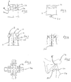
- Figure 1 is a side view of the dispensing cap, in the open configuration in which it is sold;
- Figure 2 is a side view of the dispensing cap, when closed;
- Figure 3 is an axial sectional view of the dispensing cap, in the open configuration in which it is sold;
- Figure 4 is an axial sectional view of the drinking cap, when closed;
- Figure 5 is a sectional view of the circled portion of the cap in Figure 4 on an enlarged scale; and
- Figure 6 is an end view of the piercing member of an alternative embodiment.
- The dispensing cap is a one-piece injection moulded component of polymeric material, such as polypropylene, and comprises a first circular section
tubular portion 2 of relatively large diameter, which is integrally connected at one end by a resilient,flexible web 4 to one end of a second circular section tubular portion 6 of relatively smaller diameter. - The larger
tubular portion 2 is adapted to be connected and sealed to an upper surface of a beverage container around a dispensing aperture, which is initially sealed by a membrane. The upper end of the smaller diameter tubular portion 6 is closed by anintegral lid 14, the diameter of which is greater than that of the tubular portion 6, whereby its radially outer edge constitutes a projecting peripheral flange orlip 16, which may be grasped by the user and whose radius is equal to that of the largertubular portion 2. - As may be seen in Figure 1, a plurality of holes 18 is formed in the
resilient web 4. As best seen in Figure 4, the width of theresilient web 4, that is to say its length between the lower end of the tubular portion 6 and the upper end of thetubular portion 2, is greater than the difference between the radii of the two tubular portions. Integral with the internal surface of theweb 4 is a firstannular sealing flange 20, which extends substantially in the axial direction, when the cap is in the open position illustrated in Figure 3. Integral with the internal surface of the upper end of the largertubular portion 2 is a second resilient sealingflange 22, which extends both downwardly, that is to say away from the smaller diametertubular portion 4, and inwardly towards the axis of the cap, whereby it subtends an acute angle with the axial direction of the cap. The underside of theperipheral flange 16 has an annular shoulder 8 formed in it with a radius equal to that of the upper edge of thetubular portion 2, whereby this underside has an annular portion whose shape precisely matches that of the upper edge of thetubular portion 2. The upper end of the lower tubular portion thus forms a seal not only with the underside of theflange 16 but also with the side surface of the shoulder 8. - When the cap is in the open position shown in Figures 1 and 3, the
tubular portion 4 is located wholly outside thetubular portion 2. Theweb 4 extends upwardly out of thetubular portion 2 and also inwardly in the axial direction and the flow openings 18 communicate with the interior of the cap, whereby liquid in the container to which the cap is connected can flow out through the openings 18. If a downward force is exerted on thecap 14, the tubular portion 6 begins to move downwardly. This results in compression and distortion of theweb 4, which thus exerts a restoring force on the tubular portion 6 urging it back towards the fully open position. As the force continues to be exerted on thecap 14, the tubular portion 6 moves downwardly until theweb 4 extends approximately horizontally, that is to say in the radial direction. As the tubular portion 6 moves through and beyond this "dead centre" position, the force exerted by theweb 4 on the tubular portion 6 acts in the downward direction. The tubular portion 6 continues to move downwardly and this is accompanied by continuing rotation of theweb 4. This movement continues until the underside of theperipheral flange 16 engages the upper surface of thetubular portion 2 and the free edge of the sealing flange 40 engages the surface of theresilient sealing flange 22. This occurs before theweb 4 is fully relaxed, whereby when the downward force on thecap 14 is removed, the force exerted by theweb 4 continues to urge the underside of theflange 16 against the upper surface of thetubular portion 2 to form a sealed line contact and to urge the two sealingflanges flange 20 makes sealed line contact with the surface of the sealingflange 22. The first contact line is above the flow openings 18 and thus seals them from the atmosphere whilst the second contact line is situated below the flow openings 18, which means that these flow openings are sealed from the interior of the cap. The interior of the bottle is thus sealed and no liquid can flow out through the openings 18. If it is desired to reopen the bottle, an upward force is exerted on theperipheral flange 16 and the process described above is reversed until the cap is again in the open position illustrated in Figures 1 and 3. - As mentioned above, when the cap is in the closed position, the interior of the liquid container is sealed from the exterior. If, however, a significant lateral force were exerted on one side of the
tubular portion 2, there is a risk that it could deform sufficiently to break the seal, thereby permitting liquid within the container to escape through the openings 18. This risk is minimised by the provision of an annular external stiffening or reinforcingbead 24 on the upper portion of thetubular portion 2 in the vicinity of its connection to theweb 4. This stiffening bead will resist deformation of thetubular portion 2 and thus minimise the risk of leakage occurring. - The dispensing cap as so far described is suitable for application to the mouth of a bottle for use as a drinking cap. However, the illustrated cap is particularly intended for connection to the surface of a beverage carton or the like over an aperture in the surface sealed by a rupturable membrane. In order to rupture this membrane, the cap is provided with an elongate piercing
member 30, the upper end of which is integral with the tubular portion 6 or thelid 14, which coaxially downwardly. The length of the piercing member is such that it is wholly within the cap, when the cap is in the open position, but protrudes below the lower end of thetubular portion 2, when the cap is in the closed position. - In order to ensure that the cap and thus the beverage container are not opened earlier than desired by the inadvertent application of pressure to the
lid 14, the cap is provided with an integral tear-awayplastic band 32 which is connected to theperipheral flange 16 and thetubular portion 2, which restrains relative movement of the two tubular portions. When it is desired to open the container and dispense some of the beverage in it, theplastic band 32 is grasped by a projecting tag or the like and torn away from the cap. The tubular portion is then moved downwardly into the closed position and this causes the lower end of the piercing member to extend out of the lower end of thetubular portion 2 and thus rupture the membrane sealing the aperture in the container. beverage may now be dispensed, whereafter the cap may be closed again. The fact that the plastic band has been removed is clearly visible and this band thus acts also as a tamper evident indicator. - In the embodiment of Figures 1 to 5, the piercing member is of simple, regular cruciform shape in cross-section, preferably with a relatively sharp lower end in order to facilitate rupturing the membrane. However, it is found that under certain circumstances the four portions or flaps of the ruptured membrane can return to their original position after the piercing member has been withdrawn and recreate a substantial seal. This problem is eliminated in the modified embodiment shown in Figure 6, in which the piercing member is again of generally cruciform cross-section. However, at the lower edge of each
limb 34 of the cruciform there are twolateral projections 36 extending transversely to the limb. These projections force the flaps of the ruptured membrane aside to positions from which they are unlikely to be able to return to their original position. Accordingly, use of this embodiment results in the beverage container remaining able to dispense beverage, once the membrane has been ruptured and eliminates the risk of a seal being recreated by the flaps of the ruptured membrane.
Claims (12)
- A dispensing cap constituting a one-piece moulding of polymeric material including a first circular section tubular portion with a first radius for connection to a beverage container and a second circular section tubular portion with a second radius smaller than the first radius, one end of the first tubular portion being connected to one end of the second tubular portion by a resilient, annular, integral web, in which one or more flow openings are formed, the width of the web being equal to or greater than the difference between the first and second radii, the other end of the second tubular portion being closed, the second tubular portion carrying a peripheral flange whose radius is equal to or greater than that of the first tubular portion, the first and second tubular portions being coaxial and relatively movable in the axial direction between an open position, in which the second tubular portion is located outside the first tubular portion and the flow openings are unobstructed, and a closed position, in which the said one end of the second tubular portion is located within the said one end of the first tubular portion and the peripheral flange is in sealing engagement with the said one end of the first tubular portion, whereby the flow openings are prevented from communicating with the atmosphere.
- A cap as claimed in Claim 1 in which one of the web and the internal surface of the first tubular portion adjacent the said one end carries a projecting annular first sealing flange, whereby when the first and second tubular portions are in the closed position the flow openings are prevented from communicating with the interior of the first tubular portion by the sealing engagement of the first sealing flange with the other of the web and the internal surface of the first tubular portion.
- A cap as claimed in Claim 2 in which the first sealing flange is integral with the web.
- A cap as claimed in Claim 3 in which the first sealing flange projects from the web in a direction substantially parallel to the axis of the first and second tubular portions, when they are in the open position.
- A cap as claimed in Claim 3 or 4 in which the internal surface of the first tubular portion carries a resilient annular second sealing flange, which projects at an acute angle to the axis of the first of the first and second tubular portions and away from the second tubular portion and is positioned so that it is sealingly engaged by the first sealing flange, when the first and second tubular portions are in the closed position.
- A cap as claimed in any one of the preceding claims in which the first tubular portion carries an external annular stiffening bead adjacent its connection with the web.
- A cap as claimed in any one of the preceding claims including an elongate piercing member, one end of which is connected to the second tubular portion, the piercing member being so dimensioned and arranged that, when the first and second tubular portions are in the open position, the other end is situated within the first tubular portion and when they are in the closed position it projects beyond the other end of the first tubular portion.
- A cap as claimed in Claim 7 in which the piercing member is of generally cruciform cross-sectional shape, at least at its end remote from the second tubular portion.
- A cap as claimed in Claim 8 in which each limb of the cruciform shape carries lateral displacement members on each side projecting in opposite directions to the length of the associated limb.
- A cap as claimed in any one of Claims 7 to 9 including removable retaining means which retain the first and second tubular portions in the open position.
- A cap as claimed in Claim 10 in which the retaining means are constituted by an annular strip integrally connected to the first tubular portion and to the peripheral flange on the second tubular portion by respective lines of weakness, whereby the annular strip may be manually removed when the cap is first used and will serve, prior to removal, as a tamper evident indicator.
- A cap as claimed in any one of the preceding claims in which the underside of the peripheral flange affords a radial shoulder whose shape and position match those of the upper end of the first tubular portion, whereby when the second tubular portion is moved into the closed position, the underside of the peripheral flange forms a seal with the end surface of the first tubular portion and the side surface of the shoulder forms a seal with a side surface of the first tubular portion adjacent the said end surface.
Priority Applications (5)
| Application Number | Priority Date | Filing Date | Title |
|---|---|---|---|
| PL04255277T PL1632437T3 (en) | 2004-09-01 | 2004-09-01 | Dispensing caps for beverage containers |
| AT04255277T ATE380150T1 (en) | 2004-09-01 | 2004-09-01 | PIN FOR DRINK CONTAINERS |
| DE602004010508T DE602004010508T2 (en) | 2004-09-01 | 2004-09-01 | Cones for beverage containers |
| ES04255277T ES2295785T3 (en) | 2004-09-01 | 2004-09-01 | DISPENSING PLUGS FOR DRINK CONTAINERS. |
| EP04255277A EP1632437B1 (en) | 2004-09-01 | 2004-09-01 | Dispensing caps for beverage containers |
Applications Claiming Priority (1)
| Application Number | Priority Date | Filing Date | Title |
|---|---|---|---|
| EP04255277A EP1632437B1 (en) | 2004-09-01 | 2004-09-01 | Dispensing caps for beverage containers |
Publications (2)
| Publication Number | Publication Date |
|---|---|
| EP1632437A1 true EP1632437A1 (en) | 2006-03-08 |
| EP1632437B1 EP1632437B1 (en) | 2007-12-05 |
Family
ID=34930618
Family Applications (1)
| Application Number | Title | Priority Date | Filing Date |
|---|---|---|---|
| EP04255277A Not-in-force EP1632437B1 (en) | 2004-09-01 | 2004-09-01 | Dispensing caps for beverage containers |
Country Status (5)
| Country | Link |
|---|---|
| EP (1) | EP1632437B1 (en) |
| AT (1) | ATE380150T1 (en) |
| DE (1) | DE602004010508T2 (en) |
| ES (1) | ES2295785T3 (en) |
| PL (1) | PL1632437T3 (en) |
Cited By (1)
| Publication number | Priority date | Publication date | Assignee | Title |
|---|---|---|---|---|
| JP2011162248A (en) * | 2010-02-12 | 2011-08-25 | Nihon Tetra Pak Kk | Spout with opener |
Citations (3)
| Publication number | Priority date | Publication date | Assignee | Title |
|---|---|---|---|---|
| DE8518074U1 (en) * | 1985-06-21 | 1986-02-20 | Henkel KGaA, 4000 Düsseldorf | One-piece, resealable litter lock |
| WO1994014588A1 (en) * | 1992-12-22 | 1994-07-07 | Sdt Technologies, Inc. | Closure for dispensing produce from a container |
| EP0790192A2 (en) * | 1996-02-15 | 1997-08-20 | Dart Industries Inc. | Shaker for condiments |
-
2004
- 2004-09-01 DE DE602004010508T patent/DE602004010508T2/en active Active
- 2004-09-01 ES ES04255277T patent/ES2295785T3/en active Active
- 2004-09-01 AT AT04255277T patent/ATE380150T1/en not_active IP Right Cessation
- 2004-09-01 EP EP04255277A patent/EP1632437B1/en not_active Not-in-force
- 2004-09-01 PL PL04255277T patent/PL1632437T3/en unknown
Patent Citations (3)
| Publication number | Priority date | Publication date | Assignee | Title |
|---|---|---|---|---|
| DE8518074U1 (en) * | 1985-06-21 | 1986-02-20 | Henkel KGaA, 4000 Düsseldorf | One-piece, resealable litter lock |
| WO1994014588A1 (en) * | 1992-12-22 | 1994-07-07 | Sdt Technologies, Inc. | Closure for dispensing produce from a container |
| EP0790192A2 (en) * | 1996-02-15 | 1997-08-20 | Dart Industries Inc. | Shaker for condiments |
Cited By (1)
| Publication number | Priority date | Publication date | Assignee | Title |
|---|---|---|---|---|
| JP2011162248A (en) * | 2010-02-12 | 2011-08-25 | Nihon Tetra Pak Kk | Spout with opener |
Also Published As
| Publication number | Publication date |
|---|---|
| DE602004010508T2 (en) | 2008-11-27 |
| ATE380150T1 (en) | 2007-12-15 |
| PL1632437T3 (en) | 2008-05-30 |
| DE602004010508D1 (en) | 2008-01-17 |
| EP1632437B1 (en) | 2007-12-05 |
| ES2295785T3 (en) | 2008-04-16 |
Similar Documents
| Publication | Publication Date | Title |
|---|---|---|
| US4779764A (en) | Pouring stopper | |
| EP2588384B1 (en) | Closure with tamper-evident feature | |
| CA2321076C (en) | Dispensing structure with frangible membrane for separating two products | |
| US4077538A (en) | Vendable reclosable beverage container | |
| US20040026422A1 (en) | Membrane penetrating closure with deformable top surface | |
| US4895282A (en) | Dispensing closure with pull tab for enlarging orifice | |
| US5456294A (en) | Nonspill bottled water replacement system with a shielded disposable cap | |
| US8746476B1 (en) | Closure having a seal piercing unit | |
| US20100206875A1 (en) | Package with a sealing region | |
| EP2032458B1 (en) | Upgraded bottle for fluid products, particularly pharmaceutical, medicinal or cosmetic products | |
| US6415965B2 (en) | Product dispensing system and method | |
| EP3003894B1 (en) | Closure with lid and removable membrane | |
| WO2011031639A1 (en) | Improved reclosable dispensing closure | |
| US20100140268A1 (en) | Dispensing closure with removable membrane | |
| CN1072160C (en) | Device for opening and reclosing containers | |
| US5803281A (en) | Synthetic resinous container closure having frustoconical sealing surfaces | |
| EP1954584B1 (en) | Dispensing caps for liquid containers | |
| EP2114788B1 (en) | Tamper evident closure | |
| US6073809A (en) | Snap-on tamper evident closure with push-pull pour spout | |
| EP1632437B1 (en) | Dispensing caps for beverage containers | |
| US6318605B1 (en) | Product dispensing system and method | |
| US20040007587A1 (en) | Membrane piercing closure | |
| AU2005256786B2 (en) | Dispensing caps for liquid containers | |
| US4741451A (en) | Easy open container | |
| RU181097U1 (en) | CAPPING FACILITY FOR CAPACITY |
Legal Events
| Date | Code | Title | Description |
|---|---|---|---|
| PUAI | Public reference made under article 153(3) epc to a published international application that has entered the european phase |
Free format text: ORIGINAL CODE: 0009012 |
|
| AK | Designated contracting states |
Kind code of ref document: A1 Designated state(s): AT BE BG CH CY CZ DE DK EE ES FI FR GB GR HU IE IT LI LU MC NL PL PT RO SE SI SK TR |
|
| AX | Request for extension of the european patent |
Extension state: AL HR LT LV MK |
|
| 17P | Request for examination filed |
Effective date: 20060908 |
|
| AKX | Designation fees paid |
Designated state(s): AT BE BG CH CY CZ DE DK EE ES FI FR GB GR HU IE IT LI LU MC NL PL PT RO SE SI SK TR |
|
| 17Q | First examination report despatched |
Effective date: 20061109 |
|
| GRAP | Despatch of communication of intention to grant a patent |
Free format text: ORIGINAL CODE: EPIDOSNIGR1 |
|
| GRAS | Grant fee paid |
Free format text: ORIGINAL CODE: EPIDOSNIGR3 |
|
| GRAA | (expected) grant |
Free format text: ORIGINAL CODE: 0009210 |
|
| AK | Designated contracting states |
Kind code of ref document: B1 Designated state(s): AT BE BG CH CY CZ DE DK EE ES FI FR GB GR HU IE IT LI LU MC NL PL PT RO SE SI SK TR |
|
| REG | Reference to a national code |
Ref country code: GB Ref legal event code: FG4D |
|
| REG | Reference to a national code |
Ref country code: IE Ref legal event code: FG4D |
|
| REG | Reference to a national code |
Ref country code: CH Ref legal event code: EP |
|
| REF | Corresponds to: |
Ref document number: 602004010508 Country of ref document: DE Date of ref document: 20080117 Kind code of ref document: P |
|
| REG | Reference to a national code |
Ref country code: ES Ref legal event code: FG2A Ref document number: 2295785 Country of ref document: ES Kind code of ref document: T3 |
|
| PG25 | Lapsed in a contracting state [announced via postgrant information from national office to epo] |
Ref country code: LI Free format text: LAPSE BECAUSE OF FAILURE TO SUBMIT A TRANSLATION OF THE DESCRIPTION OR TO PAY THE FEE WITHIN THE PRESCRIBED TIME-LIMIT Effective date: 20071205 Ref country code: SE Free format text: LAPSE BECAUSE OF FAILURE TO SUBMIT A TRANSLATION OF THE DESCRIPTION OR TO PAY THE FEE WITHIN THE PRESCRIBED TIME-LIMIT Effective date: 20080305 Ref country code: CH Free format text: LAPSE BECAUSE OF FAILURE TO SUBMIT A TRANSLATION OF THE DESCRIPTION OR TO PAY THE FEE WITHIN THE PRESCRIBED TIME-LIMIT Effective date: 20071205 |
|
| ET | Fr: translation filed | ||
| PG25 | Lapsed in a contracting state [announced via postgrant information from national office to epo] |
Ref country code: FI Free format text: LAPSE BECAUSE OF FAILURE TO SUBMIT A TRANSLATION OF THE DESCRIPTION OR TO PAY THE FEE WITHIN THE PRESCRIBED TIME-LIMIT Effective date: 20071205 Ref country code: SI Free format text: LAPSE BECAUSE OF FAILURE TO SUBMIT A TRANSLATION OF THE DESCRIPTION OR TO PAY THE FEE WITHIN THE PRESCRIBED TIME-LIMIT Effective date: 20071205 |
|
| REG | Reference to a national code |
Ref country code: PL Ref legal event code: T3 |
|
| REG | Reference to a national code |
Ref country code: CH Ref legal event code: PL |
|
| PG25 | Lapsed in a contracting state [announced via postgrant information from national office to epo] |
Ref country code: AT Free format text: LAPSE BECAUSE OF FAILURE TO SUBMIT A TRANSLATION OF THE DESCRIPTION OR TO PAY THE FEE WITHIN THE PRESCRIBED TIME-LIMIT Effective date: 20071205 |
|
| PG25 | Lapsed in a contracting state [announced via postgrant information from national office to epo] |
Ref country code: CZ Free format text: LAPSE BECAUSE OF FAILURE TO SUBMIT A TRANSLATION OF THE DESCRIPTION OR TO PAY THE FEE WITHIN THE PRESCRIBED TIME-LIMIT Effective date: 20071205 |
|
| PG25 | Lapsed in a contracting state [announced via postgrant information from national office to epo] |
Ref country code: RO Free format text: LAPSE BECAUSE OF FAILURE TO SUBMIT A TRANSLATION OF THE DESCRIPTION OR TO PAY THE FEE WITHIN THE PRESCRIBED TIME-LIMIT Effective date: 20071205 Ref country code: SK Free format text: LAPSE BECAUSE OF FAILURE TO SUBMIT A TRANSLATION OF THE DESCRIPTION OR TO PAY THE FEE WITHIN THE PRESCRIBED TIME-LIMIT Effective date: 20071205 Ref country code: BE Free format text: LAPSE BECAUSE OF FAILURE TO SUBMIT A TRANSLATION OF THE DESCRIPTION OR TO PAY THE FEE WITHIN THE PRESCRIBED TIME-LIMIT Effective date: 20071205 |
|
| PG25 | Lapsed in a contracting state [announced via postgrant information from national office to epo] |
Ref country code: PT Free format text: LAPSE BECAUSE OF FAILURE TO SUBMIT A TRANSLATION OF THE DESCRIPTION OR TO PAY THE FEE WITHIN THE PRESCRIBED TIME-LIMIT Effective date: 20080505 |
|
| PLBE | No opposition filed within time limit |
Free format text: ORIGINAL CODE: 0009261 |
|
| STAA | Information on the status of an ep patent application or granted ep patent |
Free format text: STATUS: NO OPPOSITION FILED WITHIN TIME LIMIT |
|
| PG25 | Lapsed in a contracting state [announced via postgrant information from national office to epo] |
Ref country code: DK Free format text: LAPSE BECAUSE OF FAILURE TO SUBMIT A TRANSLATION OF THE DESCRIPTION OR TO PAY THE FEE WITHIN THE PRESCRIBED TIME-LIMIT Effective date: 20071205 |
|
| 26N | No opposition filed |
Effective date: 20080908 |
|
| PG25 | Lapsed in a contracting state [announced via postgrant information from national office to epo] |
Ref country code: GR Free format text: LAPSE BECAUSE OF FAILURE TO SUBMIT A TRANSLATION OF THE DESCRIPTION OR TO PAY THE FEE WITHIN THE PRESCRIBED TIME-LIMIT Effective date: 20080306 |
|
| PG25 | Lapsed in a contracting state [announced via postgrant information from national office to epo] |
Ref country code: EE Free format text: LAPSE BECAUSE OF FAILURE TO SUBMIT A TRANSLATION OF THE DESCRIPTION OR TO PAY THE FEE WITHIN THE PRESCRIBED TIME-LIMIT Effective date: 20071205 Ref country code: BG Free format text: LAPSE BECAUSE OF FAILURE TO SUBMIT A TRANSLATION OF THE DESCRIPTION OR TO PAY THE FEE WITHIN THE PRESCRIBED TIME-LIMIT Effective date: 20080305 Ref country code: MC Free format text: LAPSE BECAUSE OF NON-PAYMENT OF DUE FEES Effective date: 20080930 |
|
| PG25 | Lapsed in a contracting state [announced via postgrant information from national office to epo] |
Ref country code: CY Free format text: LAPSE BECAUSE OF FAILURE TO SUBMIT A TRANSLATION OF THE DESCRIPTION OR TO PAY THE FEE WITHIN THE PRESCRIBED TIME-LIMIT Effective date: 20071205 Ref country code: IE Free format text: LAPSE BECAUSE OF NON-PAYMENT OF DUE FEES Effective date: 20080901 |
|
| PGFP | Annual fee paid to national office [announced via postgrant information from national office to epo] |
Ref country code: ES Payment date: 20090810 Year of fee payment: 6 |
|
| PGFP | Annual fee paid to national office [announced via postgrant information from national office to epo] |
Ref country code: NL Payment date: 20090821 Year of fee payment: 6 |
|
| PGFP | Annual fee paid to national office [announced via postgrant information from national office to epo] |
Ref country code: DE Payment date: 20090930 Year of fee payment: 6 |
|
| PGFP | Annual fee paid to national office [announced via postgrant information from national office to epo] |
Ref country code: IT Payment date: 20090904 Year of fee payment: 6 |
|
| PG25 | Lapsed in a contracting state [announced via postgrant information from national office to epo] |
Ref country code: LU Free format text: LAPSE BECAUSE OF NON-PAYMENT OF DUE FEES Effective date: 20080901 Ref country code: HU Free format text: LAPSE BECAUSE OF FAILURE TO SUBMIT A TRANSLATION OF THE DESCRIPTION OR TO PAY THE FEE WITHIN THE PRESCRIBED TIME-LIMIT Effective date: 20080606 |
|
| PG25 | Lapsed in a contracting state [announced via postgrant information from national office to epo] |
Ref country code: TR Free format text: LAPSE BECAUSE OF FAILURE TO SUBMIT A TRANSLATION OF THE DESCRIPTION OR TO PAY THE FEE WITHIN THE PRESCRIBED TIME-LIMIT Effective date: 20071205 |
|
| REG | Reference to a national code |
Ref country code: NL Ref legal event code: V1 Effective date: 20110401 |
|
| PG25 | Lapsed in a contracting state [announced via postgrant information from national office to epo] |
Ref country code: IT Free format text: LAPSE BECAUSE OF NON-PAYMENT OF DUE FEES Effective date: 20100901 |
|
| REG | Reference to a national code |
Ref country code: DE Ref legal event code: R119 Ref document number: 602004010508 Country of ref document: DE Effective date: 20110401 |
|
| PG25 | Lapsed in a contracting state [announced via postgrant information from national office to epo] |
Ref country code: DE Free format text: LAPSE BECAUSE OF NON-PAYMENT OF DUE FEES Effective date: 20110401 |
|
| PG25 | Lapsed in a contracting state [announced via postgrant information from national office to epo] |
Ref country code: NL Free format text: LAPSE BECAUSE OF NON-PAYMENT OF DUE FEES Effective date: 20110401 |
|
| REG | Reference to a national code |
Ref country code: ES Ref legal event code: FD2A Effective date: 20111019 |
|
| PG25 | Lapsed in a contracting state [announced via postgrant information from national office to epo] |
Ref country code: ES Free format text: LAPSE BECAUSE OF NON-PAYMENT OF DUE FEES Effective date: 20100902 |
|
| PGFP | Annual fee paid to national office [announced via postgrant information from national office to epo] |
Ref country code: PL Payment date: 20120830 Year of fee payment: 9 |
|
| PGFP | Annual fee paid to national office [announced via postgrant information from national office to epo] |
Ref country code: FR Payment date: 20121010 Year of fee payment: 9 |
|
| PGFP | Annual fee paid to national office [announced via postgrant information from national office to epo] |
Ref country code: GB Payment date: 20130830 Year of fee payment: 10 |
|
| REG | Reference to a national code |
Ref country code: FR Ref legal event code: ST Effective date: 20140530 |
|
| PG25 | Lapsed in a contracting state [announced via postgrant information from national office to epo] |
Ref country code: FR Free format text: LAPSE BECAUSE OF NON-PAYMENT OF DUE FEES Effective date: 20130930 |
|
| PG25 | Lapsed in a contracting state [announced via postgrant information from national office to epo] |
Ref country code: PL Free format text: LAPSE BECAUSE OF NON-PAYMENT OF DUE FEES Effective date: 20130901 |
|
| REG | Reference to a national code |
Ref country code: PL Ref legal event code: LAPE |
|
| GBPC | Gb: european patent ceased through non-payment of renewal fee |
Effective date: 20140901 |
|
| PG25 | Lapsed in a contracting state [announced via postgrant information from national office to epo] |
Ref country code: GB Free format text: LAPSE BECAUSE OF NON-PAYMENT OF DUE FEES Effective date: 20140901 |