EP1632424B1 - Spritzgießverfahren für ein Hybrid-Bauteil mit einem metallischen Einlegeteil - Google Patents
Spritzgießverfahren für ein Hybrid-Bauteil mit einem metallischen Einlegeteil Download PDFInfo
- Publication number
- EP1632424B1 EP1632424B1 EP20050291816 EP05291816A EP1632424B1 EP 1632424 B1 EP1632424 B1 EP 1632424B1 EP 20050291816 EP20050291816 EP 20050291816 EP 05291816 A EP05291816 A EP 05291816A EP 1632424 B1 EP1632424 B1 EP 1632424B1
- Authority
- EP
- European Patent Office
- Prior art keywords
- insert
- panel
- constituting
- tabs
- free edge
- Prior art date
- Legal status (The legal status is an assumption and is not a legal conclusion. Google has not performed a legal analysis and makes no representation as to the accuracy of the status listed.)
- Ceased
Links
- 238000001746 injection moulding Methods 0.000 title 1
- 239000004033 plastic Substances 0.000 claims description 38
- 229920003023 plastic Polymers 0.000 claims description 38
- 239000002184 metal Substances 0.000 claims description 31
- 239000000463 material Substances 0.000 claims description 19
- 238000000465 moulding Methods 0.000 claims description 18
- 238000000034 method Methods 0.000 claims description 12
- 238000005520 cutting process Methods 0.000 claims description 3
- 238000006073 displacement reaction Methods 0.000 claims description 3
- 210000002105 tongue Anatomy 0.000 description 20
- 230000003014 reinforcing effect Effects 0.000 description 3
- 238000004519 manufacturing process Methods 0.000 description 2
- 239000002990 reinforced plastic Substances 0.000 description 2
- 229910000831 Steel Inorganic materials 0.000 description 1
- 238000005452 bending Methods 0.000 description 1
- 238000010276 construction Methods 0.000 description 1
- 238000001816 cooling Methods 0.000 description 1
- 230000008878 coupling Effects 0.000 description 1
- 238000010168 coupling process Methods 0.000 description 1
- 238000005859 coupling reaction Methods 0.000 description 1
- 230000001419 dependent effect Effects 0.000 description 1
- 230000000694 effects Effects 0.000 description 1
- 238000003780 insertion Methods 0.000 description 1
- 230000037431 insertion Effects 0.000 description 1
- 238000002955 isolation Methods 0.000 description 1
- 230000003287 optical effect Effects 0.000 description 1
- 230000035939 shock Effects 0.000 description 1
- 238000007711 solidification Methods 0.000 description 1
- 230000008023 solidification Effects 0.000 description 1
- 230000003068 static effect Effects 0.000 description 1
- 239000010959 steel Substances 0.000 description 1
Images

Classifications
-
- B—PERFORMING OPERATIONS; TRANSPORTING
- B29—WORKING OF PLASTICS; WORKING OF SUBSTANCES IN A PLASTIC STATE IN GENERAL
- B29C—SHAPING OR JOINING OF PLASTICS; SHAPING OF MATERIAL IN A PLASTIC STATE, NOT OTHERWISE PROVIDED FOR; AFTER-TREATMENT OF THE SHAPED PRODUCTS, e.g. REPAIRING
- B29C45/00—Injection moulding, i.e. forcing the required volume of moulding material through a nozzle into a closed mould; Apparatus therefor
- B29C45/17—Component parts, details or accessories; Auxiliary operations
- B29C45/40—Removing or ejecting moulded articles
-
- B—PERFORMING OPERATIONS; TRANSPORTING
- B29—WORKING OF PLASTICS; WORKING OF SUBSTANCES IN A PLASTIC STATE IN GENERAL
- B29C—SHAPING OR JOINING OF PLASTICS; SHAPING OF MATERIAL IN A PLASTIC STATE, NOT OTHERWISE PROVIDED FOR; AFTER-TREATMENT OF THE SHAPED PRODUCTS, e.g. REPAIRING
- B29C45/00—Injection moulding, i.e. forcing the required volume of moulding material through a nozzle into a closed mould; Apparatus therefor
- B29C45/14—Injection moulding, i.e. forcing the required volume of moulding material through a nozzle into a closed mould; Apparatus therefor incorporating preformed parts or layers, e.g. injection moulding around inserts or for coating articles
- B29C45/1418—Injection moulding, i.e. forcing the required volume of moulding material through a nozzle into a closed mould; Apparatus therefor incorporating preformed parts or layers, e.g. injection moulding around inserts or for coating articles the inserts being deformed or preformed, e.g. by the injection pressure
-
- B—PERFORMING OPERATIONS; TRANSPORTING
- B29—WORKING OF PLASTICS; WORKING OF SUBSTANCES IN A PLASTIC STATE IN GENERAL
- B29C—SHAPING OR JOINING OF PLASTICS; SHAPING OF MATERIAL IN A PLASTIC STATE, NOT OTHERWISE PROVIDED FOR; AFTER-TREATMENT OF THE SHAPED PRODUCTS, e.g. REPAIRING
- B29C45/00—Injection moulding, i.e. forcing the required volume of moulding material through a nozzle into a closed mould; Apparatus therefor
- B29C45/14—Injection moulding, i.e. forcing the required volume of moulding material through a nozzle into a closed mould; Apparatus therefor incorporating preformed parts or layers, e.g. injection moulding around inserts or for coating articles
- B29C45/14311—Injection moulding, i.e. forcing the required volume of moulding material through a nozzle into a closed mould; Apparatus therefor incorporating preformed parts or layers, e.g. injection moulding around inserts or for coating articles using means for bonding the coating to the articles
-
- B—PERFORMING OPERATIONS; TRANSPORTING
- B62—LAND VEHICLES FOR TRAVELLING OTHERWISE THAN ON RAILS
- B62D—MOTOR VEHICLES; TRAILERS
- B62D29/00—Superstructures, understructures, or sub-units thereof, characterised by the material thereof
- B62D29/001—Superstructures, understructures, or sub-units thereof, characterised by the material thereof characterised by combining metal and synthetic material
- B62D29/004—Superstructures, understructures, or sub-units thereof, characterised by the material thereof characterised by combining metal and synthetic material the metal being over-moulded by the synthetic material, e.g. in a mould
-
- B—PERFORMING OPERATIONS; TRANSPORTING
- B29—WORKING OF PLASTICS; WORKING OF SUBSTANCES IN A PLASTIC STATE IN GENERAL
- B29L—INDEXING SCHEME ASSOCIATED WITH SUBCLASS B29C, RELATING TO PARTICULAR ARTICLES
- B29L2031/00—Other particular articles
- B29L2031/30—Vehicles, e.g. ships or aircraft, or body parts thereof
- B29L2031/3002—Superstructures characterized by combining metal and plastics, i.e. hybrid parts
Definitions
- the invention relates to a method of molding a motor vehicle front end comprising a metal insert and a plastic part overmolded on the metal insert.
- hybrid parts are manufactured and used with a metal insert and a plastic part overmolded on the metal insert.
- construction elements can be made in the form of hybrid parts that can be of large dimensions such as technical front faces fixed to a motor vehicle structure, in a transverse arrangement, at the front of the engine.
- the technical front panels provide support elements for body parts and components such as optical blocks, bumpers, grilles, heat exchangers, horns and bonnet locks.
- the subassemblies thus obtained, called front blocks, make it possible to fix all the components and devices in a single operation on the production line of motor vehicles.
- the front blocks can be manufactured in a workshop of the car manufacturer or at equipment manufacturers.
- the hybrid embodiment of the front faces has emerged as a solution to meet requirements generally contrary to the properties of the structural element, for example the requirements of lightness and mechanical strength, in particular shocks.
- the technical front faces are fixed to the front part of two longitudinal members of the motor vehicle and most often connected to the front wings of the vehicle, in a vertical transverse plane YZ of the motor vehicle.
- such front faces comprise a plastic plate made integral by overmolding a metal reinforcing element extending in the longitudinal direction of the front face, that is to say the transverse direction of the motor vehicle.
- the metal reinforcing element is generally made in the form of a profile having a channel-shaped cross section.
- the overmolded plastic material is made integral with the metal reinforcing element, in particular along the longitudinal edges of the channel-shaped profile, through holes passing through the walls of the channel in the vicinity of their free edges or sections of the wall of the metal channel folded by a only side of the walls of the canal.
- Such attachment modes of the plastic material overmolded on the metal element generally do not allow to obtain a very strong connection because the openings along the edge of the channel can be provided only in spaced areas, in the case of the first embodiment, and that the folded portions of the edge of the channel, in the case of the second embodiment, can not be entirely embedded in the plastic, so that we can ensure the demolding without providing complex parts in the underdog .
- US 6,378,268 describes a method of molding a technical front face, the insert comprises hooking tabs.
- the relative displacement of the technical front face and the moving part of the mold at the time of demolding is in a direction inclined relative to the tongues.
- US 5,580,122 discloses a technical front face with a metal insert having holes to allow attachment of the overmolded plastic material.
- the object of the invention is therefore to provide a method of molding a hybrid part comprising a metal insert and a plastic part overmolded on the metal insert in which are embedded in the attachment elements of the metal insert, which makes it possible to obtain a very strong connection between the metal insert and the plastic material, while being of simple implementation and making it possible to easily demold the workpiece without providing complex shapes in the same manner.
- FIG. 1 there is shown a portion of a free edge 1a of a metal insert cut from a sheet, for example steel, for producing a hybrid part.
- incisions 2 are made, along the entire thickness of the flat plate, in a direction perpendicular to the edge 1a and over a length I 1 , two successive incisions 2 being separated by a constant distance I 2 .
- the distance I 2 may be substantially equal to 20 mm.
- Each of the incisions 2 is made from the edge 1a of the insert 1 on the length l 1 , to the line 4 parallel to the edge 1a constituting a fold line of the zones 3 of the insert in a subsequent operation of alternating folding.
- the edge of the plate-shaped insert 1 is shown after alternately folding the zones 3 at 90 ° around the direction 4 parallel to the edge 1a of the insert 1.
- the successive zones 3 are folded alternately on one side and the other of the plate 1, that is to say at 90 ° with respect to a first and a second faces of the insert.
- hooking tabs 5 are obtained in a plane generally perpendicular to the plate intersecting the plate along line 4.
- Each of the tongues 5 folded on one side of the plate is between two tongues 5 folded on the other side. of the plate.
- Each latching tongue 5 is thus between two free spaces 6, on each side of the plane insert.
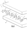
- the insert 1 after folding, is placed in a mold, for example in a mold 7 in two parts 7a, 7b, movable relative to each other.
- the mold 7 has been shown in the open state, the two parts 7a, 7b of the mold being spaced apart from each other.
- the insert 1 is introduced into the mold in the open state, so that the edge of the insert comprising the hooking tongues 5 is in a part of the cavity of the mold in which the plastic material penetrates during the molding.
- the mold schematically represented on the figure 2 may comprise different cavities and cores for molding a hybrid part of particular shape, for example a technical front having plastic walls perpendicular to the flat plate of the insert 1 along its edge 1a on which have In this case, the part of the insert 1 comprising the tongues 5 is inserted into a part of the mold cavity ensuring the molding of a plastic wall perpendicular to the plate of the mold. the insert 1 and on both sides.
- the mold After insertion of the insert and possibly cores into the molding mold, the mold is closed by bringing the two parts 7a and 7b (arrow 8) closer together and a plastic is injected into the mold, in particular in the mold. the part of the cavity into which the tongues 5 are inserted for molding the reinforced plastic wall perpendicular to the plate of the insert 1.
- the opening and closing direction of the mold (double arrow 8) is parallel to the plane in which the tabs 5 are folded which is perpendicular to the plate of the insert 1.
- the mold After solidification and cooling of the injected plastic material, the mold is opened in the direction of opening given by the double arrow 8 which is parallel to the hooking tabs 5 completely embedded in the plastic material.
- Release of the hybrid part can be done easily, because it is made perpendicular to the plate of the insert 1, that is to say in the direction of the plane of the tongues 5 and the plastic wall overmoulded reinforced by the tabs 5.
- the attachment of the plastic material on the insert is made very resistant, since the tongues 5 are completely embedded in the plastic which also fills the free spaces 6 between the tongues.
- the method according to the invention therefore makes it easy to produce hybrid parts with a very good connection between a metal insert and a plastic material and comprising, in particular, plastic walls which may be perpendicular to the planar insert.
- the hybrid part which comprises a core perfectly secured to the overmolded plastic material has a low temperature dependence, that is to say a very limited effect of the temperature of use on its natural frequencies and its mechanical characteristics.
- the Young's modulus of plastics strongly depends on the temperature.
- the manufacture of hybrid parts comprising a reinforced plastic wall on one side of the flat plate of the insert can be envisaged.
- the insert 1 can be made, as a whole, in the form of a flat plate or comprise, in addition to the plate-shaped flat portion, other non-planar parts or other inserts.
Landscapes
- Engineering & Computer Science (AREA)
- Mechanical Engineering (AREA)
- Manufacturing & Machinery (AREA)
- Architecture (AREA)
- Structural Engineering (AREA)
- Chemical & Material Sciences (AREA)
- Combustion & Propulsion (AREA)
- Transportation (AREA)
- Injection Moulding Of Plastics Or The Like (AREA)
Claims (6)
- Verfahren zum Gießen einer vorderen Funktionsfläche eines Kraftfahrzeugs, mit einem metallischen Einsatz (1) und einem Abschnitt aus Plastikmaterial, der von dem metallischen Einsatz (1) abgeformt ist und in welchem Ankopplungselemente (5) des metallischen Einsatzes (1) eingelassen sind, gekennzeichnet durch- Verwirklichen eines metallischen Einsatzes (1), der zumindest einen im Wesentlichen plattenförmigen Abschnitt mit zumindest einem freien Rand (1a) an zumindest einer Seite des metallischen Einsatzes (1) hat,- Verwirklichen von aufeinanderfolgenden Einschnitten (2) entlang dem freien Rand (1a) des plattenförmigen Abschnitts des Einsatzes (1) und entlang seiner gesamten Dicke, wobei die Einschnitte eine im Wesentlichen konstante Länge in einer Richtung haben, die im Wesentlichen senkrecht auf dem freien Rand (1a) steht, wobei die Einschnitte voneinander in Richtung des freien Rands (1a) derart beabstandet sind, dass eine Vielzahl von aufeinanderfolgenden Bereichen (3) des plattenförmigen Abschnitts des Einsatzes (1) erhalten wird, die voneinander durch einen Einschnitt (2) getrennt sind,- Umbiegen der aufeinanderfolgenden Bereiche (3) des plattenförmigen Abschnitts des Einsatzes (1) an einer Linie (4), die im Wesentlichen parallel zu dem freien Rand (1a) des Einsatzes (1) ist und durch die dem freien Rand (1a) gegenüberliegenden Enden der Einschnitte (2) verläuft, um eine Vielzahl von Ankopplungszungen (5) in zumindest einer Ebene mit einer Anordnung in einem Winkel in Bezug auf den plattenförmigen Abschnitt zu erhalten, wobei die Ankopplungszungen durch Freiräume (6) entlang des freien Rands (1a) des Einsatzes (1) an einer Seite von zumindest dem plattenförmigen Abschnitt des Einsatzes (1) getrennt sind,- Platzieren von zumindest einem die Ankopplungszungen (5) aufweisenden Abschnitt des Einsatzes (1) in eine Gussform (7a, 7b) zum Gießen der vorderen Funktionsfläche,- Einspritzen des Plastikmaterials in die Gussform (7a, 7b) derart, dass die Ankopplungszungen (5) des Einsatzes (1) in dem Plastikmaterial eingelassen sind, und- Trennen der abgekühlten vorderen Funktionsfläche von der Gießform (7a, 7b) durch Relativverschiebung der gegossenen vorderen Funktionsfläche und zumindest eines Abschnitts der Gießform (7a, 7b) in eine Richtung parallel zu den Ankopplungszungen (5).
- Verfahren gemäß Anspruch 1, dadurch gekennzeichnet, dass der metallische Einsatz durch Schneiden eines Metallblechs verwirklicht wird, wobei der gesamte Einsatz (1) in Form einer im Wesentlichen ebenen Platte ist.
- Verfahren gemäß einem der Ansprüche 1 oder 2, dadurch gekennzeichnet, dass die aufeinanderfolgenden Bereiche (3) des plattenförmigen Abschnitts des Einsatzes (1) um 90° in Bezug auf die Ebene des plattenförmigen Abschnitts des Einsatzes (1) gebogen sind.
- Verfahren gemäß Anspruch 3, dadurch gekennzeichnet, dass die Bereiche (3) des plattenförmigen Abschnitts des Einsatzes (1) abwechselnd auf die eine und andere Seite des plattenförmigen Abschnitts des Einsatzes (1) gebogen sind, wobei jede der Zungen (5) an einer Seite des plattenförmigen Abschnitts des Einsatzes (1) zwischen zwei Freiräumen (6) angeordnet ist, die zwei aufeinanderfolgende Zungen (5) trennen, die auf die gleiche Seite des plattenförmigen Abschnitts des Einsatzes (1) umgeknickt sind.
- Verfahren gemäß einem der Ansprüche 1 bis 4, dadurch gekennzeichnet, dass das Plastikmaterial in einen Abschnitt der Vertiefung der Gießform (7) eingespritzt wird, in welchem die Zungen (5) eingesetzt sind, so dass eine Wandung der vorderen Funktionsfläche erhalten wird, die durch die Zungen (5), die in einem Winkel in Bezug auf den plattenförmigen Abschnitt des Einsatzes (1) angeordnet sind, verstärkt wird.
- Verfahren gemäß Anspruch 5, dadurch gekennzeichnet, dass die Zungen (5) um 90° in Bezug auf den plattenförmigen Abschnitt des Einsatzes (1) umgebogen werden, und dass durch Gießen zumindest eine Wandung aus einem Plastikmaterial verwirklicht wird, die durch die Zungen (5) verstärkt wird, die im Wesentlichen senkrecht auf dem plattenförmigen Abschnitt des Einsatzes (1) stehen.
Priority Applications (1)
| Application Number | Priority Date | Filing Date | Title |
|---|---|---|---|
| EP11164811A EP2368786B1 (de) | 2004-09-03 | 2005-08-31 | Technisches Front-End, das ein Metalleinsatzteil und ein Plastikteil umfasst |
Applications Claiming Priority (1)
| Application Number | Priority Date | Filing Date | Title |
|---|---|---|---|
| FR0409360A FR2874853B1 (fr) | 2004-09-03 | 2004-09-03 | Procede de moulage d'une piece hybride comportant un insert metallique et une partie en matiere plastique et piece hybride obtenue |
Related Child Applications (2)
| Application Number | Title | Priority Date | Filing Date |
|---|---|---|---|
| EP11164811A Division EP2368786B1 (de) | 2004-09-03 | 2005-08-31 | Technisches Front-End, das ein Metalleinsatzteil und ein Plastikteil umfasst |
| EP11164811.9 Division-Into | 2011-05-04 |
Publications (2)
| Publication Number | Publication Date |
|---|---|
| EP1632424A1 EP1632424A1 (de) | 2006-03-08 |
| EP1632424B1 true EP1632424B1 (de) | 2012-07-25 |
Family
ID=34949858
Family Applications (2)
| Application Number | Title | Priority Date | Filing Date |
|---|---|---|---|
| EP11164811A Ceased EP2368786B1 (de) | 2004-09-03 | 2005-08-31 | Technisches Front-End, das ein Metalleinsatzteil und ein Plastikteil umfasst |
| EP20050291816 Ceased EP1632424B1 (de) | 2004-09-03 | 2005-08-31 | Spritzgießverfahren für ein Hybrid-Bauteil mit einem metallischen Einlegeteil |
Family Applications Before (1)
| Application Number | Title | Priority Date | Filing Date |
|---|---|---|---|
| EP11164811A Ceased EP2368786B1 (de) | 2004-09-03 | 2005-08-31 | Technisches Front-End, das ein Metalleinsatzteil und ein Plastikteil umfasst |
Country Status (2)
| Country | Link |
|---|---|
| EP (2) | EP2368786B1 (de) |
| FR (1) | FR2874853B1 (de) |
Families Citing this family (2)
| Publication number | Priority date | Publication date | Assignee | Title |
|---|---|---|---|---|
| US8750949B2 (en) | 2011-01-11 | 2014-06-10 | Apple Inc. | Engagement features and adjustment structures for electronic devices with integral antennas |
| FR3022173A1 (fr) * | 2014-06-11 | 2015-12-18 | Faurecia Sieges Automobile | Adhesion directe par surmoulage pour assemblage multi-materiaux |
Family Cites Families (7)
| Publication number | Priority date | Publication date | Assignee | Title |
|---|---|---|---|---|
| JPS5598696A (en) * | 1979-01-22 | 1980-07-26 | Hitachi Ltd | Multi-vane blower runner |
| JPS6030544B2 (ja) * | 1980-11-27 | 1985-07-17 | 橋本フオ−ミング工業株式会社 | モ−ルデイングの製造方法 |
| DE4409081C1 (de) | 1994-03-17 | 1995-04-20 | Daimler Benz Ag | Baueinheit für den Stirnwand- und Cockpitbereich eines Personenkraftwagens |
| JP3205955B2 (ja) * | 1995-12-08 | 2001-09-04 | エヌオーケー株式会社 | 樹脂成形品の軸孔部インサート金具の埋設構造 |
| JP2960047B1 (ja) * | 1998-04-13 | 1999-10-06 | 東北ムネカタ株式会社 | 複合筐体 |
| FR2781713B1 (fr) * | 1998-07-29 | 2000-10-13 | Plastic Omnium Cie | Procede d'ancrage d'une masse de matiere thermoplastique et piece obtenue par mise en oeuvre de ce procede |
| FR2798355B1 (fr) * | 1999-09-15 | 2001-12-14 | Valeo Thermique Moteur Sa | Element de structure composite, notamment support de face avant pour vehicule |
-
2004
- 2004-09-03 FR FR0409360A patent/FR2874853B1/fr not_active Expired - Fee Related
-
2005
- 2005-08-31 EP EP11164811A patent/EP2368786B1/de not_active Ceased
- 2005-08-31 EP EP20050291816 patent/EP1632424B1/de not_active Ceased
Also Published As
| Publication number | Publication date |
|---|---|
| FR2874853B1 (fr) | 2007-12-07 |
| FR2874853A1 (fr) | 2006-03-10 |
| EP2368786B1 (de) | 2012-08-22 |
| EP2368786A1 (de) | 2011-09-28 |
| EP1632424A1 (de) | 2006-03-08 |
Similar Documents
| Publication | Publication Date | Title |
|---|---|---|
| EP0679565B1 (de) | Vorderfront eines Kraftfahrzeuges | |
| FR2827235A1 (fr) | Poutre de pare-chocs de vehicule automobile et pare-chocs muni d'une telle poutre | |
| EP0269470B1 (de) | Verfahren zur Herstellung eines Rahmens aus Verbundwerkstoff | |
| FR2938024A1 (fr) | Clip de fixation | |
| FR2999468A1 (fr) | Cale pour moule a compression a etancheite amelioree | |
| EP1778451A1 (de) | Form zum spritzgiessen eines kunststoffteils und gussverfahren | |
| EP1632424B1 (de) | Spritzgießverfahren für ein Hybrid-Bauteil mit einem metallischen Einlegeteil | |
| EP0332495B1 (de) | Verfahren zur Herstellung von Automobil-Karosserieteilen, insbesondere Heckspoiler und nach diesem Verfahren hergestellte Gegenstände | |
| WO2015049339A1 (fr) | Moule de surmoulage d'un insert composite et procédé de surmoulage associé | |
| FR2729913A1 (fr) | Procede de fabrication d'une piece d'equipement notamment d'un vehicule automobile et planche de bord fabriquee selon ce procede | |
| EP2147768B1 (de) | Verfahren zur Herstellung eines technischen Front-Ends, und Werkzeug zum Überspritzen eines technischen Front-Ends | |
| FR2946562A1 (fr) | Procede de postionnement et d'assemblage de deux pieces dont l'une au moins est moulee en un materiau sensible au fluage | |
| FR2874889A1 (fr) | Face avant technique de vehicule automobile en metal et matiere plastique et son procede de fabrication | |
| EP2125496B1 (de) | Armaturenbrettanordnung, baugruppe dafür und anlage zur herstellung | |
| FR2805504A1 (fr) | Face avant avec absorbeur d'energie pour vehicule automobile | |
| EP3636410B1 (de) | Herstellungsverfahren eines aufformteils, das ein strukturteil eines fahrzeugs bildet | |
| EP1044850B1 (de) | Verkleidungsanordnung für einen Kraftfahrzeugblechteil | |
| FR3066152A1 (fr) | Volet pour dispositif d’obturation de face avant | |
| FR2544250A1 (fr) | Procede et dispositif de fabrication par moulage d'une boite a eau d'un echangeur de chaleur, en particulier pour vehicule automobile, et boite a eau ainsi obtenue | |
| EP2441648B1 (de) | Kraftfahrzeug-Lenkgetriebegehäuse mit Verstärkungselement | |
| FR3030427A1 (fr) | Assemblage d'inserts de renfort par un materiau polymere, a inserts de renfort separables. | |
| EP3898306B1 (de) | Gehäuse für ein stirnseitenmodul eines kraftfahrzeugs | |
| LU82944A1 (fr) | Procede de fabrication par moulage de pieces en matiere plastique notamment de pieces de grandes dimensions | |
| EP1867463A1 (de) | Verfahren zur Verbindung von Drähten durch Spiegelschweißen | |
| EP1486402A1 (de) | Fahrzeugteil aus Kunststoff und dessen Zusammenbau mit einem anderem Fahrzeugteil |
Legal Events
| Date | Code | Title | Description |
|---|---|---|---|
| PUAI | Public reference made under article 153(3) epc to a published international application that has entered the european phase |
Free format text: ORIGINAL CODE: 0009012 |
|
| AK | Designated contracting states |
Kind code of ref document: A1 Designated state(s): AT BE BG CH CY CZ DE DK EE ES FI FR GB GR HU IE IS IT LI LT LU LV MC NL PL PT RO SE SI SK TR |
|
| AX | Request for extension of the european patent |
Extension state: AL BA HR MK YU |
|
| 17P | Request for examination filed |
Effective date: 20060904 |
|
| AKX | Designation fees paid |
Designated state(s): DE FR |
|
| 17Q | First examination report despatched |
Effective date: 20101210 |
|
| GRAP | Despatch of communication of intention to grant a patent |
Free format text: ORIGINAL CODE: EPIDOSNIGR1 |
|
| RTI1 | Title (correction) |
Free format text: INJECTION MOULDING METHOD FOR A HYBRID PART WITH A METALLIC INSERT |
|
| GRAS | Grant fee paid |
Free format text: ORIGINAL CODE: EPIDOSNIGR3 |
|
| GRAA | (expected) grant |
Free format text: ORIGINAL CODE: 0009210 |
|
| AK | Designated contracting states |
Kind code of ref document: B1 Designated state(s): DE FR |
|
| REG | Reference to a national code |
Ref country code: DE Ref legal event code: R096 Ref document number: 602005035263 Country of ref document: DE Effective date: 20120920 |
|
| PLBE | No opposition filed within time limit |
Free format text: ORIGINAL CODE: 0009261 |
|
| STAA | Information on the status of an ep patent application or granted ep patent |
Free format text: STATUS: NO OPPOSITION FILED WITHIN TIME LIMIT |
|
| 26N | No opposition filed |
Effective date: 20130426 |
|
| REG | Reference to a national code |
Ref country code: DE Ref legal event code: R097 Ref document number: 602005035263 Country of ref document: DE Effective date: 20130426 |
|
| REG | Reference to a national code |
Ref country code: FR Ref legal event code: PLFP Year of fee payment: 12 |
|
| REG | Reference to a national code |
Ref country code: FR Ref legal event code: PLFP Year of fee payment: 13 |
|
| PGFP | Annual fee paid to national office [announced via postgrant information from national office to epo] |
Ref country code: FR Payment date: 20170720 Year of fee payment: 13 Ref country code: DE Payment date: 20170719 Year of fee payment: 13 |
|
| REG | Reference to a national code |
Ref country code: DE Ref legal event code: R119 Ref document number: 602005035263 Country of ref document: DE |
|
| PG25 | Lapsed in a contracting state [announced via postgrant information from national office to epo] |
Ref country code: DE Free format text: LAPSE BECAUSE OF NON-PAYMENT OF DUE FEES Effective date: 20190301 |
|
| PG25 | Lapsed in a contracting state [announced via postgrant information from national office to epo] |
Ref country code: FR Free format text: LAPSE BECAUSE OF NON-PAYMENT OF DUE FEES Effective date: 20180831 |