EP1632389A2 - Automotive vehicle seat - Google Patents
Automotive vehicle seat Download PDFInfo
- Publication number
- EP1632389A2 EP1632389A2 EP05291768A EP05291768A EP1632389A2 EP 1632389 A2 EP1632389 A2 EP 1632389A2 EP 05291768 A EP05291768 A EP 05291768A EP 05291768 A EP05291768 A EP 05291768A EP 1632389 A2 EP1632389 A2 EP 1632389A2
- Authority
- EP
- European Patent Office
- Prior art keywords
- seat
- backrest
- rotation
- frame
- axis
- Prior art date
- Legal status (The legal status is an assumption and is not a legal conclusion. Google has not performed a legal analysis and makes no representation as to the accuracy of the status listed.)
- Granted
Links
Images

Classifications
-
- B—PERFORMING OPERATIONS; TRANSPORTING
- B60—VEHICLES IN GENERAL
- B60N—SEATS SPECIALLY ADAPTED FOR VEHICLES; VEHICLE PASSENGER ACCOMMODATION NOT OTHERWISE PROVIDED FOR
- B60N2/00—Seats specially adapted for vehicles; Arrangement or mounting of seats in vehicles
- B60N2/02—Seats specially adapted for vehicles; Arrangement or mounting of seats in vehicles the seat or part thereof being movable, e.g. adjustable
- B60N2/22—Seats specially adapted for vehicles; Arrangement or mounting of seats in vehicles the seat or part thereof being movable, e.g. adjustable the back-rest being adjustable
-
- B—PERFORMING OPERATIONS; TRANSPORTING
- B60—VEHICLES IN GENERAL
- B60N—SEATS SPECIALLY ADAPTED FOR VEHICLES; VEHICLE PASSENGER ACCOMMODATION NOT OTHERWISE PROVIDED FOR
- B60N2/00—Seats specially adapted for vehicles; Arrangement or mounting of seats in vehicles
- B60N2/24—Seats specially adapted for vehicles; Arrangement or mounting of seats in vehicles for particular purposes or particular vehicles
- B60N2/30—Non-dismountable or dismountable seats storable in a non-use position, e.g. foldable spare seats
- B60N2/3002—Non-dismountable or dismountable seats storable in a non-use position, e.g. foldable spare seats back-rest movements
- B60N2/302—Non-dismountable or dismountable seats storable in a non-use position, e.g. foldable spare seats back-rest movements by translation only
- B60N2/3027—Non-dismountable or dismountable seats storable in a non-use position, e.g. foldable spare seats back-rest movements by translation only along vertical axis
-
- B—PERFORMING OPERATIONS; TRANSPORTING
- B60—VEHICLES IN GENERAL
- B60N—SEATS SPECIALLY ADAPTED FOR VEHICLES; VEHICLE PASSENGER ACCOMMODATION NOT OTHERWISE PROVIDED FOR
- B60N2/00—Seats specially adapted for vehicles; Arrangement or mounting of seats in vehicles
- B60N2/24—Seats specially adapted for vehicles; Arrangement or mounting of seats in vehicles for particular purposes or particular vehicles
- B60N2/30—Non-dismountable or dismountable seats storable in a non-use position, e.g. foldable spare seats
- B60N2/3002—Non-dismountable or dismountable seats storable in a non-use position, e.g. foldable spare seats back-rest movements
- B60N2/3029—Non-dismountable or dismountable seats storable in a non-use position, e.g. foldable spare seats back-rest movements by composed movement
- B60N2/3031—Non-dismountable or dismountable seats storable in a non-use position, e.g. foldable spare seats back-rest movements by composed movement in a longitudinal-vertical plane
-
- B—PERFORMING OPERATIONS; TRANSPORTING
- B60—VEHICLES IN GENERAL
- B60N—SEATS SPECIALLY ADAPTED FOR VEHICLES; VEHICLE PASSENGER ACCOMMODATION NOT OTHERWISE PROVIDED FOR
- B60N2/00—Seats specially adapted for vehicles; Arrangement or mounting of seats in vehicles
- B60N2/24—Seats specially adapted for vehicles; Arrangement or mounting of seats in vehicles for particular purposes or particular vehicles
- B60N2/30—Non-dismountable or dismountable seats storable in a non-use position, e.g. foldable spare seats
- B60N2/3038—Cushion movements
- B60N2/3063—Cushion movements by composed movement
- B60N2/3065—Cushion movements by composed movement in a longitudinal-vertical plane
-
- B—PERFORMING OPERATIONS; TRANSPORTING
- B60—VEHICLES IN GENERAL
- B60N—SEATS SPECIALLY ADAPTED FOR VEHICLES; VEHICLE PASSENGER ACCOMMODATION NOT OTHERWISE PROVIDED FOR
- B60N2/00—Seats specially adapted for vehicles; Arrangement or mounting of seats in vehicles
- B60N2/24—Seats specially adapted for vehicles; Arrangement or mounting of seats in vehicles for particular purposes or particular vehicles
- B60N2/30—Non-dismountable or dismountable seats storable in a non-use position, e.g. foldable spare seats
- B60N2/3088—Non-dismountable or dismountable seats storable in a non-use position, e.g. foldable spare seats characterised by the mechanical link
- B60N2/309—Non-dismountable or dismountable seats storable in a non-use position, e.g. foldable spare seats characterised by the mechanical link rods
-
- B—PERFORMING OPERATIONS; TRANSPORTING
- B60—VEHICLES IN GENERAL
- B60N—SEATS SPECIALLY ADAPTED FOR VEHICLES; VEHICLE PASSENGER ACCOMMODATION NOT OTHERWISE PROVIDED FOR
- B60N2/00—Seats specially adapted for vehicles; Arrangement or mounting of seats in vehicles
- B60N2/24—Seats specially adapted for vehicles; Arrangement or mounting of seats in vehicles for particular purposes or particular vehicles
- B60N2/30—Non-dismountable or dismountable seats storable in a non-use position, e.g. foldable spare seats
- B60N2/3088—Non-dismountable or dismountable seats storable in a non-use position, e.g. foldable spare seats characterised by the mechanical link
- B60N2/3093—Non-dismountable or dismountable seats storable in a non-use position, e.g. foldable spare seats characterised by the mechanical link slides
-
- B—PERFORMING OPERATIONS; TRANSPORTING
- B60—VEHICLES IN GENERAL
- B60N—SEATS SPECIALLY ADAPTED FOR VEHICLES; VEHICLE PASSENGER ACCOMMODATION NOT OTHERWISE PROVIDED FOR
- B60N2/00—Seats specially adapted for vehicles; Arrangement or mounting of seats in vehicles
- B60N2/24—Seats specially adapted for vehicles; Arrangement or mounting of seats in vehicles for particular purposes or particular vehicles
- B60N2/32—Seats specially adapted for vehicles; Arrangement or mounting of seats in vehicles for particular purposes or particular vehicles convertible for other use
- B60N2/36—Seats specially adapted for vehicles; Arrangement or mounting of seats in vehicles for particular purposes or particular vehicles convertible for other use into a loading platform
-
- B—PERFORMING OPERATIONS; TRANSPORTING
- B60—VEHICLES IN GENERAL
- B60N—SEATS SPECIALLY ADAPTED FOR VEHICLES; VEHICLE PASSENGER ACCOMMODATION NOT OTHERWISE PROVIDED FOR
- B60N2/00—Seats specially adapted for vehicles; Arrangement or mounting of seats in vehicles
- B60N2/64—Back-rests or cushions
- B60N2/643—Back-rests or cushions shape of the back-rests
-
- B—PERFORMING OPERATIONS; TRANSPORTING
- B60—VEHICLES IN GENERAL
- B60N—SEATS SPECIALLY ADAPTED FOR VEHICLES; VEHICLE PASSENGER ACCOMMODATION NOT OTHERWISE PROVIDED FOR
- B60N2/00—Seats specially adapted for vehicles; Arrangement or mounting of seats in vehicles
- B60N2/02—Seats specially adapted for vehicles; Arrangement or mounting of seats in vehicles the seat or part thereof being movable, e.g. adjustable
- B60N2/22—Seats specially adapted for vehicles; Arrangement or mounting of seats in vehicles the seat or part thereof being movable, e.g. adjustable the back-rest being adjustable
- B60N2002/2204—Adjustable back-rest height or length
Definitions
- the present invention relates to a seat for a motor vehicle and more particularly a rear seat.
- retractable seats which are designed to be able to tilt the seat in a housing provided below the floor of the vehicle and fold the backrest above said seat to close the housing and determine a flat and continuous loading floor.
- this type of seat offers no possibility of adjusting the height of the backrest position according to the morphology of the passenger and, in its retracted position, it occupies an important place.
- the tilting of the seat requires a significant effort because, most often, the rear portion of the seat pad is recessed below the backrest pad so that the bottom of this folder is a point that must be crossed to fold the seat.
- the invention aims to provide a motor vehicle seat and in particular a rear seat, which avoids the disadvantages mentioned above.
- the invention therefore relates to a motor vehicle seat and more particularly to a rear seat, of the type comprising a seat and a back each formed by a rigid frame and a lining, characterized in that the frame of the backrest comprises means of sliding said backrest relative to the seat between a high position and a low position.
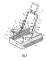
- FIG. 1 schematically shows a seat of a motor vehicle, including a rear seat, generally designated by the reference 1.
- this seat 1 consists of a seat 2 and a backrest 5.
- the seat 2 consists of a rigid frame 3 and a lining 4 coating said rigid frame 3 and, likewise, the backrest 5 consists of a rigid frame 6 and a lining 7 coating said rigid frame 6 .
- the armature 3 of the seat 2 is constituted, inter alia, of two parallel flanges, respectively 3a and 3b, and extending parallel to the longitudinal direction of the vehicle.
- the frame 6 of the backrest 5 consists of a frame 6a disposed between two parallel uprights, 7a and 7b respectively. These uprights 7a and 7b provide the connection, on the one hand, between the frame 6 of the backrest 5 and the frame 3 of the seat 2 and, on the other hand, between this frame 6 and the floor 10 of the motor vehicle .
- the frame 6 of the backrest 5 comprises means for sliding said backrest relative to the seat 2 between an upper position (FIG 1) and a lower position (FIG 2) and means of simultaneous tilting of the seat 2 and the backrest 5 on the floor 10 between a position of use (Figs 1 and 2) and a retracted position (Fig 5) in which the seat 2 is placed horizontally in a housing 11 arranged below the floor 10 and the backrest 5 is placed horizontally above said seat 2 to form a part of said floor 10.
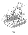
- the sliding means are arranged between the two uprights 7a and 7b and the frame 6a of the frame 6 of the backrest 5.
- These sliding means comprise a first assembly 35a formed by a fixed part 36a carried by the upright 7a and a movable part 37a carried by the frame 6a and a second assembly 35b formed by a fixed part 36b carried by the upright 7b and by a movable part 37b carried by said frame 6a of the frame 6.
- These sets 35a and 35b allow movement in one direction substantially vertical backrest 5 between a high position Fig. 1 and a low position 2 and in an intermediate position between these two extreme positions.
- the assemblies 35a and 35b are each formed by a ball slide or by a rack system or by a system of stepwise displacement associated with locking means.
- the simultaneous tilting means of the seat 2 and the backrest 5 between the use position and the retracted position comprise three axes of rotation, respectively 20, 30 and 40, extending parallel to each other and perpendicular to each other. the longitudinal direction of the motor vehicle.
- the first axis of rotation 20 is constituted by a rod 21 extending between the two flanges 3a and 3b and which is mounted articulated on a end of a link 22 whose other end is articulated on the floor 10 of the motor vehicle.
- the axis of rotation constituted by the rod 21 is articulated between two rods 22 extending parallel to each other and each mounted to the front end of one of the flanges 3a and 3b of the frame 3 of the seat 2.
- the end of each rod 22 opposite that articulated to the axis of rotation 21 is pivotally mounted on the floor 10 of the motor vehicle.
- the second axis of rotation 30 is disposed at the rear of the frame 3 of the seat 2 and at the upper part of this seat 2.
- This axis of rotation 30 extends perpendicular to the longitudinal direction of the vehicle and is constituted on the one hand, by a pin 31 mounted articulated between the flange 3a of the armature 3 and the upright 7a of the armature 7 and, on the other hand, by a pin 32 mounted hinged between the flange 3b of this armature 3 of the seat 2 and the amount 7b of the frame 6 of the back 5.
- the pins 31 and 32 are arranged on the same horizontal axis.
- the third axis of rotation 40 is disposed at the lower part of the frame 6 of the backrest 5 and extends perpendicularly to the longitudinal direction of the motor vehicle.
- the axis of rotation 40 is longitudinally displaceable in at least one slideway 50 disposed on the floor 10 of the motor vehicle.
- the axis of rotation 40 is constituted, on the one hand, of a pin 41 disposed at the lower end of the upright 7a and which is movable longitudinally in a slideway 5 and, on the other hand, by a pin 42 disposed at the lower end of the upright 7b and which is also movable in a slideway 50, said slideways 50 being parallel to each other and extending parallel to the longitudinal direction of the motor vehicle.
- the armature 3 of the seat 2 comprises, at its front part, a stop 24 against the rods 22 in the position of use of the seat 2 and the backrest 5 and which consists of a rod extending transversely between the flanges 3a and 3b of said frame 3 of the seat 2.
- the frame 3 of this seat 2 also comprises, at its rear part, a stop 25 against the uprights 7a and 7b of the frame 6 of the backrest in the position of use of the seat 2 and the backrest 5 of said seat 1.
- This stop 25 is constituted by a rod extending transversely between the flanges 3a and 3b of the armature 3 of the seat 2 and which is disposed below the second axis of rotation 30.
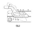
- the seat 1 comprises locking means in the position of use of this seat and which are shown in particular in FIG. 3.
- the locking means are constituted by a latch 55 mounted articulated on one of the slides 50 and which has a notch 56 intended to cooperate with the pin 41 or 42 corresponding to the slideway and for example with the pin 42.
- the latch 45 is hingedly mounted on the slide 50 by means of a pivot pin 57 and is equipped with a control lever 58 for moving said latch 55 between an active locking position of the pin 42 of the third axis of rotation 40 and a retracted position of release of this piece 42.
- the latch 55 is also provided with an elastic member for returning the latch 55 in the active position.
- This elastic member is constituted for example by a spring system 59 disposed around the axis 57 and which comprises, in a conventional manner, a first end 59a integral with the latch 55 and a second end 59b integral with the slideway 50.
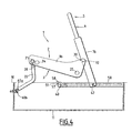
- the end of at least one link 22 articulated on the floor 10 is provided with an elastic member 60 for returning this connecting rod 22 in the position of use of the seat 2 and the backrest 5.
- this return member is constituted by a spring system 60 disposed around the axis of the corresponding end of the rod 22 and which has a first end 60a fixed on the rod 22 and a second end 60b fixed on the floor 10.
- the passenger makes a pull on the backrest 5 to move it upward or a push on the backrest 5 to move it downwards and get the position that he wishes.
- the user moves the folder 5 down as shown in FIG. 2, so as to reduce the clutter upward of the backrest 5 relative to the seat 2. Then the user tilts towards the front of the motor vehicle, the backrest 5 so that the seat 2 down to the floor 10 pivoting about the axes of rotation 20 and 30 and that the rods 22 pivot about their articulated end on said floor 10.
- the backrest 5 pivots around the pins 31 and 32 of the axis of rotation 30 and also around the pins 41 and 42 of the axis of rotation 40. Simultaneously with this pivoting, these pins 41 and 42 slide in the slides 50 towards the rear of the motor vehicle, as shown in FIG. 4.
- the seat therefore tilts gradually in the retracted position shown in FIG. 5, wherein the seat 2 is placed in the housing 11 formed in the floor 10 and the backrest 5 closes the housing 11 forming a continuous surface with said floor 10.
- the pin 42 tilts the latch 55 downwards and is housed in the notch 56 of the latch 55 which is returned to the locking position by the elastic member 59.
- the stop 24 is supported on the rods 22 and the abutment 25 is supported on the uprights 7a and 7b of the frame 6a of the backrest 5.
- the user adjusts the height of the backrest 5 relative to the seat 2.
- this seat has a minimum of space in its retracted position, while maintaining sufficient seat trim volumes and backrest to accommodate passengers of different morphologies.
- the tilting system of the seat according to the invention has the advantage of requiring a very low maneuvering force and the backrest does not interfere with the tilting of this seat.
- the seat according to the invention offers the possibility of having a flat loading floor and large area, while protecting the seat and backrest upholstery in the retracted position of this seat. It also allows by performing simple maneuvers, to modulate the number of seats according to the passengers, as well as the load volume according to the loads to be transported.
Landscapes
- Engineering & Computer Science (AREA)
- Aviation & Aerospace Engineering (AREA)
- Transportation (AREA)
- Mechanical Engineering (AREA)
- Seats For Vehicles (AREA)
- Air-Conditioning For Vehicles (AREA)
- Automatic Cycles, And Cycles In General (AREA)
Abstract
L'invention a pour objet un siège de véhicule automobile, du type comprenant une assise (2) et un dossier (5) formés chacun par une armature rigide (3 ; 6) et un garnissage (4 ; 7), caractérisé en ce que l'armature (6) du dossier (5) comporte des moyens (35a, 35b) de coulissement dudit dossier (5) par rapport à l'assise (2) entre une position haute et une position basse. L'invention s'applique aux sièges arrière de véhicules automobiles.The invention relates to a motor vehicle seat, of the type comprising a seat (2) and a backrest (5) each formed by a rigid frame (3; 6) and a lining (4; 7), characterized in that the armature (6) of the backrest (5) comprises means (35a, 35b) for sliding said backrest (5) relative to the seat (2) between a high position and a low position. The invention applies to the rear seats of motor vehicles.
Description
La présente invention concerne un siège pour véhicule automobile et plus particulièrement un siège arrière.The present invention relates to a seat for a motor vehicle and more particularly a rear seat.
Les véhicules automobiles par exemple du type monospace ou break sont maintenant équipés, derrière la rangée de sièges avant, de sièges arrière qui sont modulables de façon à adapter l'habitabilité du véhicule en fonction du nombre de passagers et/ou des charges à transporter.Motor vehicles for example of the MPV type or station wagon are now equipped, behind the row of front seats, rear seats that are adjustable to adapt the livability of the vehicle based on the number of passengers and / or loads to be transported.
Pour cela, on connaît des sièges démontables qui peuvent être enlevés pour agrandir le volume de chargement. Le principal inconvénient de cette solution réside dans la nécessité du démontage.For this, there are known removable seats that can be removed to enlarge the load volume. The main disadvantage of this solution lies in the need for disassembly.
En effet, il faut libérer les différents sièges de leur ancrage sur le plancher du véhicule et ranger les sièges démontés, en dehors du véhicule, dans des locaux. Lorsque l'on a besoin d'une place pour un passager supplémentaire, il faut de nouveau rechercher le siège et procéder à son remontage. Ainsi, l'adaptation de l'espace interne du véhicule en fonction de son utilisation nécessite un temps de préparation et des efforts importants. De plus, en milieu urbain, le possesseur d'un tel véhicule ne dispose pas toujours d'un local permettant le stockage des sièges enlevés.Indeed, it is necessary to release the various seats from their anchorage on the floor of the vehicle and stow the disassembled seats, outside the vehicle, in premises. When a seat for an additional passenger is needed, the seat must be retrieved and reassembled. Thus, the adaptation of the internal space of the vehicle according to its use requires a time of preparation and significant efforts. In addition, in urban areas, the owner of such a vehicle does not always have a room for storing removed seats.
On connaît aussi des sièges qui sont conçus pour pouvoir basculer l'assise derrière la rangée de sièges située devant et rabattre le dossier de façon à augmenter le volume de chargement. Mais, ce type de siège ne permet pas d'obtenir un plancher de chargement continu et plat.Also known are seats that are designed to tilt the seat behind the row of seats in front and fold down the backrest to increase the load volume. But, this type of seat does not provide a continuous and flat loading floor.
On connaît également des sièges escamotables qui sont conçus pour pouvoir basculer l'assise dans un logement ménagé au-dessous du plancher du véhicule et rabattre le dossier au-dessus de ladite assise pour fermer le logement et déterminer un plancher de chargement continu et plat.Also known are retractable seats which are designed to be able to tilt the seat in a housing provided below the floor of the vehicle and fold the backrest above said seat to close the housing and determine a flat and continuous loading floor.
Mais, ce type de siège n'offre aucune possibilité de réglage en hauteur de la position du dossier en fonction de la morphologie du passager et, dans sa position escamotée, il occupe une place importante.But, this type of seat offers no possibility of adjusting the height of the backrest position according to the morphology of the passenger and, in its retracted position, it occupies an important place.
De plus, le basculement du siège demande un effort important du fait que, le plus souvent, la partie arrière de la garniture de l'assise est encastrée au-dessous de la garniture du dossier si bien que la partie inférieure de ce dossier constitue un point qu'il faut franchir pour rabattre l'assise.In addition, the tilting of the seat requires a significant effort because, most often, the rear portion of the seat pad is recessed below the backrest pad so that the bottom of this folder is a point that must be crossed to fold the seat.
L'invention a pour but de proposer un siège de véhicule automobile et notamment un siège arrière, qui évite les inconvénients précédemment mentionnés.The invention aims to provide a motor vehicle seat and in particular a rear seat, which avoids the disadvantages mentioned above.
L'invention a donc pour objet un siège de véhicule automobile et plus particulièrement un siège arrière, du type comprenant une assise et un dossier formés chacun par une armature rigide et un garnissage, caractérisé en ce que l'armature du dossier comporte des moyens de coulissement dudit dossier par rapport à l'assise entre une position haute et une position basse.The invention therefore relates to a motor vehicle seat and more particularly to a rear seat, of the type comprising a seat and a back each formed by a rigid frame and a lining, characterized in that the frame of the backrest comprises means of sliding said backrest relative to the seat between a high position and a low position.
Selon d'autres caractéristiques de l'invention :
- l'assise et le dossier sont montés déplaçables simultanément par des moyens de basculement sur un plancher du véhicule entre une position d'utilisation et une position escamotée dans laquelle cette assise est placée horizontalement dans un logement ménagé au-dessous du plancher et ce dossier est placé horizontalement au-dessus de ladite assise pour former une partie dudit plancher,
- les moyens de coulissement sont disposés entre deux montants parallèles et l'armature du dossier et comportent, pour chaque montant, un ensemble formé par une partie fixe portée par le montant correspondant et par une partie mobile portée par l'armature du dossier et destinée à coopérer avec ladite partie fixe,
- chaque ensemble des moyens de coulissement est formé par une glissière à billes ou par un système à crémaillère ou par un système de déplacement pas à pas,
- les moyens de basculement comprennent :
- à l'avant de l'armature de l'assise, un premier axe de rotation perpendiculaire à la direction longitudinale du véhicule et articulé sur une extrémité d'au moins une biellette dont l'autre extrémité est articulée sur le plancher,
- à l'arrière de l'armature de l'assise et à la partie supérieure de cette assise, un deuxième axe de rotation perpendiculaire à la direction longitudinale du véhicule et articulé sur les montants, et
- à la partie inférieure de l'armature du dossier et au-dessous de ladite assise, un troisième axe de rotation perpendiculaire à la direction longitudinale du véhicule et disposé à l'extrémité inférieure des montants, ledit troisième axe de rotation étant déplaçable longitudinalement dans au moins une glissière placée sur le plancher,
- le siège comporte des moyens de verrouillage de l'armature du dossier dans la position d'utilisation de l'assise et du dossier.
- the seat and the backrest are mounted simultaneously movable by tilting means on a floor of the vehicle between a position of use and a retracted position in which this seat is placed horizontally in a housing formed below the floor and this folder is placed horizontally above said seat to form a part of said floor,
- the sliding means are arranged between two parallel uprights and the backrest frame and comprise, for each upright, an assembly formed by a fixed part carried by the corresponding amount and by a movable part carried by the backrest frame and intended for cooperate with said fixed part,
- each set of sliding means is formed by a ball slide or by a rack system or by a displacement system step by step,
- the switching means comprise:
- at the front of the frame of the seat, a first axis of rotation perpendicular to the longitudinal direction of the vehicle and articulated on one end of at least one rod whose other end is hinged to the floor,
- at the rear of the frame of the seat and at the upper part of this seat, a second axis of rotation perpendicular to the longitudinal direction of the vehicle and articulated on the uprights, and
- at the lower part of the backrest frame and below said seat, a third axis of rotation perpendicular to the longitudinal direction of the vehicle and disposed at the lower end of the uprights, said third axis of rotation being longitudinally displaceable in at minus a slide placed on the floor,
- the seat comprises locking means of the backrest frame in the position of use of the seat and backrest.
D'autres caractéristiques et avantages de l'invention apparaîtront au cours de la description qui va suivre, donnée à titre d'exemple et faite en référence aux dessins annexés, sur lesquels :
- la Fig. 1 est une vue schématique en perspective d'un siège conforme à l'invention avec le dossier en position haute,
- la Fig. 2 est une vue schématique en perspective du siège conforme à l'invention avec le dossier en position basse,
- la Fig. 3 est une vue schématique des moyens de verrouillage du siège dans sa position d'utilisation, et
- les Figs. 4 et 5 sont des vues schématiques de côté du siège selon l'invention montrant la cinématique de basculement de ce siège.
- FIG. 1 is a schematic perspective view of a seat according to the invention with the backrest in the up position,
- FIG. 2 is a schematic perspective view of the seat according to the invention with the backrest in the low position,
- FIG. 3 is a schematic view of the locking means of the seat in its position of use, and
- Figs. 4 and 5 are schematic side views of the seat according to the invention showing the tilting kinematics of this seat.
Sur la Fig. 1, on a représenté schématiquement un siège d'un véhicule automobile, notamment un siège arrière, désigné dans son ensemble par la référence 1. De manière classique, ce siège 1 se compose d'une assise 2 et d'un dossier 5.In FIG. 1, schematically shows a seat of a motor vehicle, including a rear seat, generally designated by the
L'assise 2 se compose d'une armature rigide 3 et d'une garniture 4 enrobant ladite armature rigide 3 et, de même, le dossier 5 se compose d'une armature rigide 6 et d'une garniture 7 enrobant ladite armature rigide 6.The
Afin de faciliter la compréhension, uniquement les armatures 3 et 6 respectivement de l'assise 2 et du dossier 5 ont été représentées sur les Figs. 2, 4 et 5.To facilitate understanding, only the
Ainsi que montré plus particulièrement sur les Figs. 1 et 2, l'armature 3 de l'assise 2 est constituée, entre autres, de deux flasques parallèles, respectivement 3a et 3b, et s'étendant parallèlement à la direction longitudinale du véhicule. L'armature 6 du dossier 5 est constituée d'un cadre 6a disposé entre deux montants parallèles, respectivement 7a et 7b. Ces montants 7a et 7b assurent la liaison, d'une part, entre l'armature 6 du dossier 5 et l'armature 3 de l'assise 2 et, d'autre part, entre cette armature 6 et le plancher 10 du véhicule automobile.As shown more particularly in FIGS. 1 and 2, the
D'une manière générale, l'armature 6 du dossier 5 comporte des moyens de coulissement dudit dossier par rapport à l'assise 2 entre une position haute (Fig. 1) et une position basse (Fig. 2) ainsi que des moyens de basculement simultané de l'assise 2 et du dossier 5 sur le plancher 10 entre une position d'utilisation (Figs. 1 et 2) et une position escamotée (Fig. 5) dans laquelle l'assise 2 est placée horizontalement dans un logement 11 ménagé au-dessous du plancher 10 et le dossier 5 est placé horizontalement au-dessus de ladite assise 2 pour former une partie dudit plancher 10.In general, the
Les moyens de coulissement sont disposés entre les deux montants 7a et 7b et le cadre 6a de l'armature 6 du dossier 5. Ces moyens de coulissement comportent un premier ensemble 35a formé par une partie fixe 36a portée par le montant 7a et une partie mobile 37a portée par le cadre 6a et un second ensemble 35b formé par une partie fixe 36b portée par le montant 7b et par une partie mobile 37b portée par ledit cadre 6a de l'armature 6. Ces ensembles 35a et 35b permettent le déplacement dans une direction sensiblement verticale du dossier 5 entre une position haute Fig. 1 et une position basse Fig. 2 et dans une position intermédiaire située entre ces deux positions extrêmes.The sliding means are arranged between the two
A titre d'exemple, les ensembles 35a et 35b sont chacun formé par une glissière à billes ou par un système à crémaillère ou par un système de déplacement pas à pas associé à des moyens de blocage.By way of example, the
Les moyens de basculement simultanés de l'assise 2 et du dossier 5 entre la position d'utilisation et la position escamotée comprennent trois axes de rotation, respectivement 20, 30 et 40, s'étendant parallèlement les uns par rapport aux autres et perpendiculairement à la direction longitudinale du véhicule automobile.The simultaneous tilting means of the
Le premier axe de rotation 20 est constitué par une tige 21 s'étendant entre les deux flasques 3a et 3b et qui est montée articulée sur une extrémité d'une biellette 22 dont l'autre extrémité est montée articulée sur le plancher 10 du véhicule automobile.The first axis of
De préférence et selon le mode de réalisation représenté sur les figures, l'axe de rotation 20 constitué par la tige 21 est monté articulé entre deux biellettes 22 s'étendant parallèlement l'une par rapport à l'autre et montées chacune à l'extrémité avant d'un des flasques 3a et 3b de l'armature 3 de l'assise 2. L'extrémité de chaque biellette 22 opposée à celle articulée à l'axe de rotation 21 est montée articulée sur le plancher 10 du véhicule automobile.Preferably and according to the embodiment shown in the figures, the axis of rotation constituted by the
Le deuxième axe de rotation 30 est disposé à l'arrière de l'armature 3 de l'assise 2 et à la partie supérieure de cette assise 2. Cet axe de rotation 30 s'étend perpendiculairement à la direction longitudinale du véhicule et est constitué, d'une part, par un pion 31 monté articulé entre le flasque 3a de l'armature 3 et le montant 7a de l'armature 7 et, d'autre part, par un pion 32 monté articulé entre le flasque 3b de cette armature 3 de l'assise 2 et le montant 7b de l'armature 6 du dossier 5. Les pions 31 et 32 sont disposés sur le même axe horizontal.The second axis of
Enfin, le troisième axe de rotation 40 est disposé à la partie inférieure de l'armature 6 du dossier 5 et s'étend perpendiculairement à la direction longitudinale du véhicule automobile. L'axe de rotation 40 est déplaçable longitudinalement dans au moins une glissière 50 disposée sur le plancher 10 du véhicule automobile.Finally, the third axis of
De préférence et comme représenté notamment à la Fig. 1, l'axe de rotation 40 est constitué, d'une part, d'un pion 41 disposé à l'extrémité inférieure du montant 7a et qui est déplaçable longitudinalement dans une glissière 5 et, d'autre part, par un pion 42 disposé à l'extrémité inférieure du montant 7b et qui est également déplaçable dans une glissière 50, lesdites glissières 50 étant parallèles l'une par rapport à l'autre et s'étendant parallèlement à la direction longitudinale du véhicule automobile.Preferably and as shown in particular in FIG. 1, the axis of
L'armature 3 de l'assise 2 comporte, à sa partie avant, une butée 24 contre les biellettes 22 dans la position d'utilisation de l'assise 2 et du dossier 5 et qui est constituée par une tige s'étendant transversalement entre les flasques 3a et 3b de ladite armature 3 de l'assise 2. L'armature 3 de cette assise 2 comporte aussi, à sa partie arrière, une butée 25 contre les montants 7a et 7b de l'armature 6 du dossier dans la position d'utilisation de l'assise 2 et du dossier 5 dudit siège 1. Cette butée 25 est constituée par une tige s'étendant transversalement entre les flasques 3a et 3b de l'armature 3 de l'assise 2 et qui est disposée au-dessous du deuxième axe de rotation 30.The
Enfin, le siège 1 comporte des moyens de verrouillage dans la position d'utilisation de ce siège et qui sont représentés notamment à la Fig. 3.Finally, the
Comme montré sur cette figure, les moyens de verrouillage sont constitués par un loquet 55 monté articulé sur une des glissières 50 et qui comporte une encoche 56 destinée à coopérer avec le pion 41 ou 42 correspondant à la glissière et par exemple avec le pion 42.As shown in this figure, the locking means are constituted by a
Le loquet 45 est monté articulé sur la glissière 50 au moyen d'un axe de pivotement 57 et est équipé d'un levier de commande 58 permettant de déplacer ledit loquet 55 entre une position active de blocage du pion 42 du troisième axe de rotation 40 et une position escamotée de libération de ce pion 42.The latch 45 is hingedly mounted on the
Le loquet 55 est également muni d'un organe élastique de rappel du loquet 55 en position active. Cet organe élastique est constitué par exemple par un système à ressort 59 disposé autour de l'axe 57 et qui comporte, de manière classique, une première extrémité 59a solidaire du loquet 55 et une seconde extrémité 59b solidaire de la glissière 50.The
De même, l'extrémité d'au moins une biellette 22 articulée sur le plancher 10 est pourvue d'un organe élastique 60 de rappel de cette bielle 22 en position d'utilisation de l'assise 2 et du dossier 5.Similarly, the end of at least one
Ainsi que montré à la Fig. 4, cet organe de rappel est constitué par un système à ressort 60 disposé autour de l'axe de l'extrémité correspondante de la biellette 22 et qui comporte une première extrémité 60a fixée sur cette biellette 22 et une seconde extrémité 60b fixée sur le plancher 10.As shown in FIG. 4, this return member is constituted by a
Pour régler la position du dossier 5 par rapport à l'assise 2 du siège 1, le passager effectue une traction sur le dossier 5 pour le déplacer vers le haut ou une poussée sur ce dossier 5 pour le déplacer vers le bas et obtenir la position qu'il souhaite.To adjust the position of the
Par ailleurs, le basculement du siège 1 entre la position d'utilisation et la position escamotée est réalisé de la façon suivante.Furthermore, the tilting of the
Tout d'abord futilisateur déplace le dossier 5 vers le bas, comme montré à la Fig. 2, de façon à diminuer l'encombrement vers le haut de ce dossier 5 par rapport à l'assise 2. Puis l'utilisateur bascule vers l'avant du véhicule automobile, le dossier 5 de telle manière que l'assise 2 descende vers le plancher 10 en pivotant autour des axes de rotation 20 et 30 et que les biellettes 22 pivotent autour de leur extrémité articulée sur ledit plancher 10.First of all, the user moves the
Au cours de ce mouvement, le dossier 5 pivote autour des pions 31 et 32 de l'axe de rotation 30 et également autour des pions 41 et 42 de l'axe de rotation 40. Simultanément à ce pivotement, ces pions 41 et 42 coulissent dans les glissières 50 vers l'arrière du véhicule automobile, ainsi que montré à la Fig. 4.During this movement, the
Le siège bascule donc progressivement dans la position escamotée représentée à la Fig. 5, dans laquelle l'assise 2 est placée dans le logement 11 ménagé dans le plancher 10 et le dossier 5 obture ce logement 11 en formant une surface continue avec ledit plancher 10.The seat therefore tilts gradually in the retracted position shown in FIG. 5, wherein the
Compte tenu de la position basse du dossier 5, ce dernier occupe un minimum de place dans le logement 11.Given the low position of the
Pour amener le siège dans sa position d'utilisation, il suffit à l'utilisateur de basculer le dossier 5 vers l'arrière du véhicule automobile de telle manière que les pions 41 et 42 de l'axe de rotation 40 coulissent dans les glissières 50 vers l'avant de ce véhicule et progressivement l'assise 2 revient en position d'utilisation.To bring the seat into its position of use, it is sufficient for the user to tilt the
Au cours de ce mouvement, le pion 42 bascule le loquet 55 vers le bas et vient se loger dans l'encoche 56 de ce loquet 55 qui est ramené en position de verrouillage par l'organe élastique 59. En position d'utilisation, la butée 24 est en appui sur les biellettes 22 et la butée 25 est en appui sur les montants 7a et 7b du cadre 6a du dossier 5.During this movement, the
Ensuite, l'utilisateur règle la hauteur du dossier 5 par rapport à l'assise 2.Then, the user adjusts the height of the
Grâce au coulissement du dossier du siège selon l'invention, ce siège présente un minimum de place dans sa position escamotée, tout en conservant des volumes de garnitures de l'assise et du dossier suffisants pour accueillir des passagers de différentes morphologies. De plus, le système de basculement du siège selon l'invention présente l'avantage de ne demander qu'un effort de manoeuvre très faible et le dossier ne gêne en rien le basculement de cette assise.Thanks to the sliding of the seat back according to the invention, this seat has a minimum of space in its retracted position, while maintaining sufficient seat trim volumes and backrest to accommodate passengers of different morphologies. In addition, the tilting system of the seat according to the invention has the advantage of requiring a very low maneuvering force and the backrest does not interfere with the tilting of this seat.
Enfin, le siège selon l'invention offre la possibilité de pouvoir disposer d'un plancher de chargement plat et de grande surface, tout en protégeant les garnitures de l'assise et du dossier dans la position escamotée de ce siège. Il permet également en effectuant des manoeuvres simples, de moduler le nombre de places en fonction des passagers, ainsi que le volume de chargement selon les charges à transporter.Finally, the seat according to the invention offers the possibility of having a flat loading floor and large area, while protecting the seat and backrest upholstery in the retracted position of this seat. It also allows by performing simple maneuvers, to modulate the number of seats according to the passengers, as well as the load volume according to the loads to be transported.
Claims (8)
Applications Claiming Priority (1)
| Application Number | Priority Date | Filing Date | Title |
|---|---|---|---|
| FR0409410A FR2874869B1 (en) | 2004-09-06 | 2004-09-06 | SEAT FOR MOTOR VEHICLE |
Publications (3)
| Publication Number | Publication Date |
|---|---|
| EP1632389A2 true EP1632389A2 (en) | 2006-03-08 |
| EP1632389A3 EP1632389A3 (en) | 2007-10-10 |
| EP1632389B1 EP1632389B1 (en) | 2012-03-07 |
Family
ID=34948987
Family Applications (1)
| Application Number | Title | Priority Date | Filing Date |
|---|---|---|---|
| EP05291768A Expired - Lifetime EP1632389B1 (en) | 2004-09-06 | 2005-08-23 | Automotive vehicle seat |
Country Status (3)
| Country | Link |
|---|---|
| EP (1) | EP1632389B1 (en) |
| AT (1) | ATE548217T1 (en) |
| FR (1) | FR2874869B1 (en) |
Cited By (13)
| Publication number | Priority date | Publication date | Assignee | Title |
|---|---|---|---|---|
| EP1884401A1 (en) * | 2006-07-27 | 2008-02-06 | C.R.F. Società Consortile per Azioni | Seat assembly provided with an articulated-quadrilaterial supporting device for a motor vehicle |
| WO2008104348A1 (en) * | 2007-02-26 | 2008-09-04 | Johnson Controls Gmbh | Vehicle seat |
| DE102007055144A1 (en) * | 2007-11-19 | 2009-05-20 | Ford-Werke Gmbh | Seat i.e. middle seat, for use in seat arrangement in vehicle, has back part longitudinally-changeable between one final position at which back part exhibits greater length formed as seat length and another final position |
| DE102008023888A1 (en) * | 2008-05-16 | 2009-11-19 | GM Global Technology Operations, Inc., Detroit | Vehicle seat for use as rear vehicle seat in passenger car, has backrest transferable from use position into load position, where volume of cushion and/or backrest is made smaller during transfer from use position into load position |
| JP2010519131A (en) * | 2007-02-26 | 2010-06-03 | ジョンソン・コントロールズ・ゲー・エム・ベー・ハー | Vehicle seat |
| DE102007005144B4 (en) * | 2007-02-01 | 2010-12-02 | Faurecia Autositze Gmbh | Motor vehicle with a vehicle seat arrangement |
| US8313146B2 (en) | 2010-01-20 | 2012-11-20 | Ford Global Technologies, Llc | Stowable vehicle seat |
| FR2980457A1 (en) * | 2011-09-27 | 2013-03-29 | Airbus Operations Sas | Retractable armchair for cabin of aircraft, has telescopic element with lower part that swivels with regard to floor to place armchair in retracted position between reinforcements, and base connected to upper part in swiveling manner |
| EP2255993A3 (en) * | 2009-05-13 | 2013-11-20 | Johnson Controls GmbH | Vehicle seat with a banana-shaped connector between the backrest and the seat base |
| EP2708410A1 (en) * | 2012-09-14 | 2014-03-19 | Grammer Ag | Seat, in particular a vehicle seat, with high pivot axis |
| CN105291900A (en) * | 2015-11-25 | 2016-02-03 | 重庆工商大学 | Automobile seat assembly and telescopic backrest type automobile seat |
| WO2018156238A1 (en) * | 2017-02-22 | 2018-08-30 | L & P Property Management Company | Integrated lumbar and head tilt assembly |
| US20200023757A1 (en) * | 2018-07-19 | 2020-01-23 | Ford Global Technologies, Llc | Av and transport scissor jack rear seat system |
Families Citing this family (1)
| Publication number | Priority date | Publication date | Assignee | Title |
|---|---|---|---|---|
| WO2024069652A1 (en) * | 2022-09-27 | 2024-04-04 | Gowtham Tamminaina Sai | Seat for a saddle-type vehicle |
Family Cites Families (9)
| Publication number | Priority date | Publication date | Assignee | Title |
|---|---|---|---|---|
| US3291527A (en) * | 1966-03-07 | 1966-12-13 | Bostrom Corp | Vertical adjustable back |
| DE3704489A1 (en) * | 1987-02-13 | 1988-08-25 | Daimler Benz Ag | MOTOR CAR SEAT |
| US6152401A (en) * | 1997-12-23 | 2000-11-28 | Air Methods Corporation | Deployable chair system for use in patient transport aircraft |
| US6113191A (en) * | 1998-10-21 | 2000-09-05 | Johnson Controls Technology Company | Storable seat assembly |
| DE19925306C2 (en) * | 1999-06-02 | 2002-11-21 | Faurecia Autositze Gmbh & Co | Backrest of a motor vehicle seat |
| FR2798331B1 (en) * | 1999-09-10 | 2001-11-16 | Renault | ARRANGEMENT OF A SEAT FOR A MOTOR VEHICLE FOR TRANSPORTATION AND A BENCH COMPRISING SUCH AN ARRANGEMENT |
| FR2829441B1 (en) * | 2001-09-13 | 2004-01-02 | Renault | MOTOR VEHICLE SEAT |
| US20030214166A1 (en) * | 2002-05-15 | 2003-11-20 | Schambre John E. | Adjustable seatback assembly |
| FR2849630B1 (en) * | 2003-01-08 | 2005-03-18 | Faurecia Sieges Automobile | MOTOR VEHICLE COMPRISING AT LEAST ONE REVERSE REAR SEAT |
-
2004
- 2004-09-06 FR FR0409410A patent/FR2874869B1/en not_active Expired - Fee Related
-
2005
- 2005-08-23 EP EP05291768A patent/EP1632389B1/en not_active Expired - Lifetime
- 2005-08-23 AT AT05291768T patent/ATE548217T1/en active
Cited By (21)
| Publication number | Priority date | Publication date | Assignee | Title |
|---|---|---|---|---|
| EP1884401A1 (en) * | 2006-07-27 | 2008-02-06 | C.R.F. Società Consortile per Azioni | Seat assembly provided with an articulated-quadrilaterial supporting device for a motor vehicle |
| DE102007005144B4 (en) * | 2007-02-01 | 2010-12-02 | Faurecia Autositze Gmbh | Motor vehicle with a vehicle seat arrangement |
| DE102007005144C5 (en) * | 2007-02-01 | 2017-04-13 | Faurecia Autositze Gmbh | Motor vehicle with a vehicle seat arrangement |
| US8033604B2 (en) | 2007-02-01 | 2011-10-11 | Faurecia Autositze Gmbh | Vehicle seat system and motor vehicle having a vehicle seat system |
| DE102007053958B4 (en) * | 2007-02-26 | 2016-04-28 | Johnson Controls Gmbh | vehicle seat |
| US20110062738A1 (en) * | 2007-02-26 | 2011-03-17 | Johnson Controls Gmbh | Vehicle seat |
| JP2010519131A (en) * | 2007-02-26 | 2010-06-03 | ジョンソン・コントロールズ・ゲー・エム・ベー・ハー | Vehicle seat |
| US8608244B2 (en) | 2007-02-26 | 2013-12-17 | Johnson Controls Gmbh | Vehicle seat |
| WO2008104348A1 (en) * | 2007-02-26 | 2008-09-04 | Johnson Controls Gmbh | Vehicle seat |
| US8714619B2 (en) * | 2007-02-26 | 2014-05-06 | Johnson Controls Gmbh | Vehicle seat |
| DE102007055144A1 (en) * | 2007-11-19 | 2009-05-20 | Ford-Werke Gmbh | Seat i.e. middle seat, for use in seat arrangement in vehicle, has back part longitudinally-changeable between one final position at which back part exhibits greater length formed as seat length and another final position |
| DE102008023888A1 (en) * | 2008-05-16 | 2009-11-19 | GM Global Technology Operations, Inc., Detroit | Vehicle seat for use as rear vehicle seat in passenger car, has backrest transferable from use position into load position, where volume of cushion and/or backrest is made smaller during transfer from use position into load position |
| EP2255993A3 (en) * | 2009-05-13 | 2013-11-20 | Johnson Controls GmbH | Vehicle seat with a banana-shaped connector between the backrest and the seat base |
| US8313146B2 (en) | 2010-01-20 | 2012-11-20 | Ford Global Technologies, Llc | Stowable vehicle seat |
| FR2980457A1 (en) * | 2011-09-27 | 2013-03-29 | Airbus Operations Sas | Retractable armchair for cabin of aircraft, has telescopic element with lower part that swivels with regard to floor to place armchair in retracted position between reinforcements, and base connected to upper part in swiveling manner |
| EP2708410A1 (en) * | 2012-09-14 | 2014-03-19 | Grammer Ag | Seat, in particular a vehicle seat, with high pivot axis |
| CN105291900A (en) * | 2015-11-25 | 2016-02-03 | 重庆工商大学 | Automobile seat assembly and telescopic backrest type automobile seat |
| WO2018156238A1 (en) * | 2017-02-22 | 2018-08-30 | L & P Property Management Company | Integrated lumbar and head tilt assembly |
| US10376063B2 (en) | 2017-02-22 | 2019-08-13 | L&P Property Management Company | Integrated lumbar and head tilt assembly |
| US20200023757A1 (en) * | 2018-07-19 | 2020-01-23 | Ford Global Technologies, Llc | Av and transport scissor jack rear seat system |
| US10696198B2 (en) * | 2018-07-19 | 2020-06-30 | Ford Global Technologies, Llc | AV and transport scissor jack rear seat system |
Also Published As
| Publication number | Publication date |
|---|---|
| EP1632389A3 (en) | 2007-10-10 |
| FR2874869B1 (en) | 2007-12-21 |
| EP1632389B1 (en) | 2012-03-07 |
| ATE548217T1 (en) | 2012-03-15 |
| FR2874869A1 (en) | 2006-03-10 |
Similar Documents
| Publication | Publication Date | Title |
|---|---|---|
| EP1632389B1 (en) | Automotive vehicle seat | |
| FR2821028A1 (en) | SEAT DEVICE COMPRISING A FOLDING BACK | |
| EP1366987A1 (en) | Seat convertible into bed having a deformable armrest | |
| FR2735081A1 (en) | Adjustable seat for automobiles | |
| FR3086607A1 (en) | RETRACTABLE SHELF DEVICE FOR VEHICLE SEAT | |
| FR3083174A1 (en) | MOTOR VEHICLE SEAT | |
| FR3086606A1 (en) | MOTOR VEHICLE | |
| EP0800952B1 (en) | Forwardly displaceable automotive vehicle seat, to access the rear space | |
| EP1040961A1 (en) | Seat collapsible into an armrest for vehicle passengers | |
| FR2898554A1 (en) | Motor vehicle folding seat, has backrest leg disposed in maximum inclination position towards rear in folded position of seat corresponding to maximum displacement of base towards bottom | |
| FR2775637A1 (en) | Adjuster for independent rear seats in vehicles | |
| EP1808330B1 (en) | Seat for an automobile along a first axis x and a second axis y and automobile comprising such a seat | |
| EP0373081B1 (en) | Collapsible seat especially for the equipment of automotive vehicles | |
| EP1632391B1 (en) | Automotive vehicle seat particularly a rear seat | |
| FR2849630A1 (en) | Vehicle for transporting passenger and cargo, has seat to take normal position to receive passenger, and folded back position to store objects in rear part that has platform slidingly mounted in loading position | |
| FR2798890A1 (en) | FOOTREST FOR MOTOR VEHICLE | |
| FR2999491A1 (en) | Retractable seat for motor vehicle, has seat back and base articulated in rotation with respect to another around pivot connection, and front rod articulated in rotation around another pivot connection on rear portion of base | |
| EP1414668B1 (en) | Adjustable vehicle bench seat | |
| FR2882007A1 (en) | Motor vehicle seat arrangement, has two seats on floor pan with single housing to position one seat in retracted horizontal position, and to position seats in horizontal position retracted on each other with backrest of seats folded on base | |
| FR3117420A1 (en) | Vehicle comprising a two-position bench seat equipped with a locking system | |
| EP4015299B1 (en) | Vehicle comprising a bench seat with two positions | |
| FR2860460A1 (en) | Motor vehicle e.g. minivan, rear seat, has articulation unit allowing movement of backrest from its normal position to retracted position by combined movements of backrest around one axis and rotation of axis around another axis | |
| EP1767395B1 (en) | Foldable seat for vehicle boot | |
| EP2184202B1 (en) | Seat for an automotive vehicle | |
| EP1449712B1 (en) | Foldable seat for motor vehicle and corresponding motor vehicle |
Legal Events
| Date | Code | Title | Description |
|---|---|---|---|
| PUAI | Public reference made under article 153(3) epc to a published international application that has entered the european phase |
Free format text: ORIGINAL CODE: 0009012 |
|
| AK | Designated contracting states |
Kind code of ref document: A2 Designated state(s): AT BE BG CH CY CZ DE DK EE ES FI FR GB GR HU IE IS IT LI LT LU LV MC NL PL PT RO SE SI SK TR |
|
| AX | Request for extension of the european patent |
Extension state: AL BA HR MK YU |
|
| PUAL | Search report despatched |
Free format text: ORIGINAL CODE: 0009013 |
|
| AK | Designated contracting states |
Kind code of ref document: A3 Designated state(s): AT BE BG CH CY CZ DE DK EE ES FI FR GB GR HU IE IS IT LI LT LU LV MC NL PL PT RO SE SI SK TR |
|
| AX | Request for extension of the european patent |
Extension state: AL BA HR MK YU |
|
| RIC1 | Information provided on ipc code assigned before grant |
Ipc: B60N 2/36 20060101ALI20070831BHEP Ipc: B60N 2/22 20060101AFI20051228BHEP Ipc: B60N 2/64 20060101ALI20070831BHEP Ipc: B60N 2/30 20060101ALI20070831BHEP |
|
| 17P | Request for examination filed |
Effective date: 20080311 |
|
| 17Q | First examination report despatched |
Effective date: 20080411 |
|
| AKX | Designation fees paid |
Designated state(s): AT BE BG CH CY CZ DE DK EE ES FI FR GB GR HU IE IS IT LI LT LU LV MC NL PL PT RO SE SI SK TR |
|
| GRAP | Despatch of communication of intention to grant a patent |
Free format text: ORIGINAL CODE: EPIDOSNIGR1 |
|
| GRAS | Grant fee paid |
Free format text: ORIGINAL CODE: EPIDOSNIGR3 |
|
| GRAA | (expected) grant |
Free format text: ORIGINAL CODE: 0009210 |
|
| AK | Designated contracting states |
Kind code of ref document: B1 Designated state(s): AT BE BG CH CY CZ DE DK EE ES FI FR GB GR HU IE IS IT LI LT LU LV MC NL PL PT RO SE SI SK TR |
|
| REG | Reference to a national code |
Ref country code: GB Ref legal event code: FG4D Free format text: NOT ENGLISH |
|
| REG | Reference to a national code |
Ref country code: AT Ref legal event code: REF Ref document number: 548217 Country of ref document: AT Kind code of ref document: T Effective date: 20120315 Ref country code: CH Ref legal event code: EP |
|
| REG | Reference to a national code |
Ref country code: IE Ref legal event code: FG4D Free format text: LANGUAGE OF EP DOCUMENT: FRENCH |
|
| REG | Reference to a national code |
Ref country code: DE Ref legal event code: R096 Ref document number: 602005033011 Country of ref document: DE Effective date: 20120510 |
|
| REG | Reference to a national code |
Ref country code: NL Ref legal event code: VDEP Effective date: 20120307 |
|
| REG | Reference to a national code |
Ref country code: GB Ref legal event code: 746 Effective date: 20120702 |
|
| PG25 | Lapsed in a contracting state [announced via postgrant information from national office to epo] |
Ref country code: NL Free format text: LAPSE BECAUSE OF FAILURE TO SUBMIT A TRANSLATION OF THE DESCRIPTION OR TO PAY THE FEE WITHIN THE PRESCRIBED TIME-LIMIT Effective date: 20120307 Ref country code: LT Free format text: LAPSE BECAUSE OF FAILURE TO SUBMIT A TRANSLATION OF THE DESCRIPTION OR TO PAY THE FEE WITHIN THE PRESCRIBED TIME-LIMIT Effective date: 20120307 |
|
| LTIE | Lt: invalidation of european patent or patent extension |
Effective date: 20120307 |
|
| PG25 | Lapsed in a contracting state [announced via postgrant information from national office to epo] |
Ref country code: LV Free format text: LAPSE BECAUSE OF FAILURE TO SUBMIT A TRANSLATION OF THE DESCRIPTION OR TO PAY THE FEE WITHIN THE PRESCRIBED TIME-LIMIT Effective date: 20120307 Ref country code: FI Free format text: LAPSE BECAUSE OF FAILURE TO SUBMIT A TRANSLATION OF THE DESCRIPTION OR TO PAY THE FEE WITHIN THE PRESCRIBED TIME-LIMIT Effective date: 20120307 Ref country code: GR Free format text: LAPSE BECAUSE OF FAILURE TO SUBMIT A TRANSLATION OF THE DESCRIPTION OR TO PAY THE FEE WITHIN THE PRESCRIBED TIME-LIMIT Effective date: 20120608 |
|
| REG | Reference to a national code |
Ref country code: DE Ref legal event code: R084 Ref document number: 602005033011 Country of ref document: DE Effective date: 20120619 |
|
| REG | Reference to a national code |
Ref country code: AT Ref legal event code: MK05 Ref document number: 548217 Country of ref document: AT Kind code of ref document: T Effective date: 20120307 |
|
| PG25 | Lapsed in a contracting state [announced via postgrant information from national office to epo] |
Ref country code: CY Free format text: LAPSE BECAUSE OF FAILURE TO SUBMIT A TRANSLATION OF THE DESCRIPTION OR TO PAY THE FEE WITHIN THE PRESCRIBED TIME-LIMIT Effective date: 20120307 |
|
| PG25 | Lapsed in a contracting state [announced via postgrant information from national office to epo] |
Ref country code: EE Free format text: LAPSE BECAUSE OF FAILURE TO SUBMIT A TRANSLATION OF THE DESCRIPTION OR TO PAY THE FEE WITHIN THE PRESCRIBED TIME-LIMIT Effective date: 20120307 Ref country code: SE Free format text: LAPSE BECAUSE OF FAILURE TO SUBMIT A TRANSLATION OF THE DESCRIPTION OR TO PAY THE FEE WITHIN THE PRESCRIBED TIME-LIMIT Effective date: 20120307 Ref country code: IS Free format text: LAPSE BECAUSE OF FAILURE TO SUBMIT A TRANSLATION OF THE DESCRIPTION OR TO PAY THE FEE WITHIN THE PRESCRIBED TIME-LIMIT Effective date: 20120707 Ref country code: PL Free format text: LAPSE BECAUSE OF FAILURE TO SUBMIT A TRANSLATION OF THE DESCRIPTION OR TO PAY THE FEE WITHIN THE PRESCRIBED TIME-LIMIT Effective date: 20120307 Ref country code: RO Free format text: LAPSE BECAUSE OF FAILURE TO SUBMIT A TRANSLATION OF THE DESCRIPTION OR TO PAY THE FEE WITHIN THE PRESCRIBED TIME-LIMIT Effective date: 20120307 Ref country code: CZ Free format text: LAPSE BECAUSE OF FAILURE TO SUBMIT A TRANSLATION OF THE DESCRIPTION OR TO PAY THE FEE WITHIN THE PRESCRIBED TIME-LIMIT Effective date: 20120307 Ref country code: SI Free format text: LAPSE BECAUSE OF FAILURE TO SUBMIT A TRANSLATION OF THE DESCRIPTION OR TO PAY THE FEE WITHIN THE PRESCRIBED TIME-LIMIT Effective date: 20120307 |
|
| PG25 | Lapsed in a contracting state [announced via postgrant information from national office to epo] |
Ref country code: SK Free format text: LAPSE BECAUSE OF FAILURE TO SUBMIT A TRANSLATION OF THE DESCRIPTION OR TO PAY THE FEE WITHIN THE PRESCRIBED TIME-LIMIT Effective date: 20120307 Ref country code: PT Free format text: LAPSE BECAUSE OF FAILURE TO SUBMIT A TRANSLATION OF THE DESCRIPTION OR TO PAY THE FEE WITHIN THE PRESCRIBED TIME-LIMIT Effective date: 20120709 |
|
| PLBE | No opposition filed within time limit |
Free format text: ORIGINAL CODE: 0009261 |
|
| STAA | Information on the status of an ep patent application or granted ep patent |
Free format text: STATUS: NO OPPOSITION FILED WITHIN TIME LIMIT |
|
| PG25 | Lapsed in a contracting state [announced via postgrant information from national office to epo] |
Ref country code: AT Free format text: LAPSE BECAUSE OF FAILURE TO SUBMIT A TRANSLATION OF THE DESCRIPTION OR TO PAY THE FEE WITHIN THE PRESCRIBED TIME-LIMIT Effective date: 20120307 Ref country code: DK Free format text: LAPSE BECAUSE OF FAILURE TO SUBMIT A TRANSLATION OF THE DESCRIPTION OR TO PAY THE FEE WITHIN THE PRESCRIBED TIME-LIMIT Effective date: 20120307 |
|
| 26N | No opposition filed |
Effective date: 20121210 |
|
| BERE | Be: lapsed |
Owner name: PEUGEOT CITROEN AUTOMOBILES S.A. Effective date: 20120831 |
|
| PG25 | Lapsed in a contracting state [announced via postgrant information from national office to epo] |
Ref country code: IT Free format text: LAPSE BECAUSE OF FAILURE TO SUBMIT A TRANSLATION OF THE DESCRIPTION OR TO PAY THE FEE WITHIN THE PRESCRIBED TIME-LIMIT Effective date: 20120307 |
|
| REG | Reference to a national code |
Ref country code: CH Ref legal event code: PL |
|
| PG25 | Lapsed in a contracting state [announced via postgrant information from national office to epo] |
Ref country code: MC Free format text: LAPSE BECAUSE OF NON-PAYMENT OF DUE FEES Effective date: 20120831 |
|
| REG | Reference to a national code |
Ref country code: DE Ref legal event code: R097 Ref document number: 602005033011 Country of ref document: DE Effective date: 20121210 |
|
| GBPC | Gb: european patent ceased through non-payment of renewal fee |
Effective date: 20120823 |
|
| PG25 | Lapsed in a contracting state [announced via postgrant information from national office to epo] |
Ref country code: CH Free format text: LAPSE BECAUSE OF NON-PAYMENT OF DUE FEES Effective date: 20120831 Ref country code: ES Free format text: LAPSE BECAUSE OF FAILURE TO SUBMIT A TRANSLATION OF THE DESCRIPTION OR TO PAY THE FEE WITHIN THE PRESCRIBED TIME-LIMIT Effective date: 20120618 Ref country code: LI Free format text: LAPSE BECAUSE OF NON-PAYMENT OF DUE FEES Effective date: 20120831 |
|
| REG | Reference to a national code |
Ref country code: FR Ref legal event code: ST Effective date: 20130430 |
|
| REG | Reference to a national code |
Ref country code: IE Ref legal event code: MM4A |
|
| PG25 | Lapsed in a contracting state [announced via postgrant information from national office to epo] |
Ref country code: BE Free format text: LAPSE BECAUSE OF NON-PAYMENT OF DUE FEES Effective date: 20120831 |
|
| PG25 | Lapsed in a contracting state [announced via postgrant information from national office to epo] |
Ref country code: GB Free format text: LAPSE BECAUSE OF NON-PAYMENT OF DUE FEES Effective date: 20120823 Ref country code: BG Free format text: LAPSE BECAUSE OF FAILURE TO SUBMIT A TRANSLATION OF THE DESCRIPTION OR TO PAY THE FEE WITHIN THE PRESCRIBED TIME-LIMIT Effective date: 20120607 Ref country code: IE Free format text: LAPSE BECAUSE OF NON-PAYMENT OF DUE FEES Effective date: 20120823 Ref country code: DE Free format text: LAPSE BECAUSE OF NON-PAYMENT OF DUE FEES Effective date: 20130301 |
|
| PG25 | Lapsed in a contracting state [announced via postgrant information from national office to epo] |
Ref country code: FR Free format text: LAPSE BECAUSE OF NON-PAYMENT OF DUE FEES Effective date: 20120831 |
|
| REG | Reference to a national code |
Ref country code: DE Ref legal event code: R119 Ref document number: 602005033011 Country of ref document: DE Effective date: 20130301 |
|
| PG25 | Lapsed in a contracting state [announced via postgrant information from national office to epo] |
Ref country code: TR Free format text: LAPSE BECAUSE OF FAILURE TO SUBMIT A TRANSLATION OF THE DESCRIPTION OR TO PAY THE FEE WITHIN THE PRESCRIBED TIME-LIMIT Effective date: 20120307 |
|
| PG25 | Lapsed in a contracting state [announced via postgrant information from national office to epo] |
Ref country code: LU Free format text: LAPSE BECAUSE OF NON-PAYMENT OF DUE FEES Effective date: 20120823 |
|
| PG25 | Lapsed in a contracting state [announced via postgrant information from national office to epo] |
Ref country code: HU Free format text: LAPSE BECAUSE OF FAILURE TO SUBMIT A TRANSLATION OF THE DESCRIPTION OR TO PAY THE FEE WITHIN THE PRESCRIBED TIME-LIMIT Effective date: 20050823 |