EP1631816B1 - Dynamisches rheometer mit weitem bereich - Google Patents
Dynamisches rheometer mit weitem bereich Download PDFInfo
- Publication number
- EP1631816B1 EP1631816B1 EP04754478A EP04754478A EP1631816B1 EP 1631816 B1 EP1631816 B1 EP 1631816B1 EP 04754478 A EP04754478 A EP 04754478A EP 04754478 A EP04754478 A EP 04754478A EP 1631816 B1 EP1631816 B1 EP 1631816B1
- Authority
- EP
- European Patent Office
- Prior art keywords
- test specimen
- rheometer
- transmitter circuit
- test
- parameter information
- Prior art date
- Legal status (The legal status is an assumption and is not a legal conclusion. Google has not performed a legal analysis and makes no representation as to the accuracy of the status listed.)
- Revoked
Links
Images




Classifications
-
- G—PHYSICS
- G01—MEASURING; TESTING
- G01N—INVESTIGATING OR ANALYSING MATERIALS BY DETERMINING THEIR CHEMICAL OR PHYSICAL PROPERTIES
- G01N11/00—Investigating flow properties of materials, e.g. viscosity, plasticity; Analysing materials by determining flow properties
- G01N11/10—Investigating flow properties of materials, e.g. viscosity, plasticity; Analysing materials by determining flow properties by moving a body within the material
- G01N11/14—Investigating flow properties of materials, e.g. viscosity, plasticity; Analysing materials by determining flow properties by moving a body within the material by using rotary bodies, e.g. vane
-
- G—PHYSICS
- G01—MEASURING; TESTING
- G01N—INVESTIGATING OR ANALYSING MATERIALS BY DETERMINING THEIR CHEMICAL OR PHYSICAL PROPERTIES
- G01N11/00—Investigating flow properties of materials, e.g. viscosity, plasticity; Analysing materials by determining flow properties
- G01N2011/0006—Calibrating, controlling or cleaning viscometers
- G01N2011/0013—Temperature compensation
-
- G—PHYSICS
- G01—MEASURING; TESTING
- G01N—INVESTIGATING OR ANALYSING MATERIALS BY DETERMINING THEIR CHEMICAL OR PHYSICAL PROPERTIES
- G01N11/00—Investigating flow properties of materials, e.g. viscosity, plasticity; Analysing materials by determining flow properties
- G01N2011/0006—Calibrating, controlling or cleaning viscometers
- G01N2011/002—Controlling sample temperature; Thermal cycling during measurement
Definitions
- the present invention relates generally to the measurement of physical properties of materials and pertains, more specifically, to improvements in rheometers for performing a complete range of steady, dynamic and transient rheological analyses in sample materials ranging from lower viscosity fluids, dispersions and gels to higher viscosity polymer melts.
- test s"pecimen is in the form of a disk-like configuration and is coupled between axially spaced apart, radially-extending surfaces for the application of stress to the test specimen, it has been observed that the test specimen has a tendency to expand axially, in a direction normal to the radially-extending surfaces, requiring that the measuring devices provide some degree of compliance in order to accommodate and measure this axial, or normal, displacement.
- GB 2 356 937 A relates to a rotational rheometer with an integrated motor which rotates a measuring shaft supporting a first measuring element, there being formed between said first measuring element and a further, fixed measuring element, a measurement gap into which is introduced the substance to be tested.
- the depth of the measurement gap is variable by the adjustment of the two measuring elements relative to each other, and a device is provided to determine the distance between the two measuring elements.
- WO 97/42483 A describes a rheometer comprising a housing member, a helical flange disposed on an inner surface of said housing member, a rotor disposed concentrically within said helical flange and abutting said helical flange while maintaining sliding contact with said flange, wherein said rotor and said helical flange form a helical channel.
- the rheometer further comprises a mechanism for rotating said rotor, a mechanism for introducing a sample of said composition into one end of said channel, a mechanism for controlling removal of said sample from the other end of said channel, and a mechanism for measuring a pressure difference of said sample between an upstream location and a downstream location in said channel.
- the ability to power an electronic measurement system which includes measurement sensors placed in these moving component parts without compromising the ability of the component parts to move independent of external influences would enable a greater degree of accuracy than heretofore available in dynamic rheometers.
- measurements can be obtained more quickly and with greater accuracy, and without the necessity for extrapolations or computations in order to determine the true magnitude of the parameters indicative of the rheological characteristics being measured.
- the present invention enables measurements to be obtained directly at the moving components of a dynamic rheometer for quicker response and greater accuracy in the measurement of test parameters indicative of the rheological characteristics of a test specimen.
- the present invention attains several objects and advantages, some of which are summarized as follows: Provides an improvement in an advanced rheometer capable of performing a complete range of steady, dynamic and transient rheological analyses on sample materials ranging from low viscosity fluids, dispersions and gels to high viscosity polymer melts; enables the accomplishment of rheological testing in less time, with increased accuracy and across a wider range of performance specifications than heretofore available; raises the overall quality of measurements attained with a rheometer, accomplishes normal displacement measurements and temperature measurements in rheological test specimens with increased ease and greater accuracy; assures increased control over measurements in rheological test specimens for greater accuracy; enables simultaneous testing for a wide range of simultaneous analyses; accommodates a wide range of environmental conditions with minimal requirements at testing sites; enables direct
- the present invention includes a rheometer in which strain is effected in a test specimen in order to measure a test parameter in the test specimen, the rheometer comprising: a test parameter information sensor for juxtaposition in close proximity with the test specimen to provide information pertaining to the test parameter of the test specimen; a test parameter information transmitter circuit for receiving test parameter information from the test parameter information sensor; the test parameter information sensor and the test parameter information transmitter circuit being movable through movements corresponding to the strain effected in the test specimen; a test parameter information receptor circuit juxtaposed with the test parameter information transmitter circuit and being placed at a stationary location relative to the test parameter information transmitter circuit; an isolator arrangement isolating the stationary test parameter information receptor circuit mechanically and electrically from the movable test parameter information transmitter circuit; and a test parameter information transfer system for passing test parameter information from the movable test parameter information transmitter circuit across the isolator arrangement to the stationary test parameter information receptor circuit without a direct mechanical or electrical connection between the movable test parameter information transmitter circuit and the stationary test parameter information receptor circuit
- a rheometer is shown at 10 and is seen to include a housing 12 and a holder assembly in the form of a depending quill 14 coupled at the upper end of the quill 14 to an upper shaft 16 extending axially upwardly through an air bearing 18 to a motor assembly 20 having a central shaft 22 coupled to a drag cusp 24 placed between the stator 26 and the corepiece 28 of motor assembly 20, in an arrangement similar to that described in detail in the aforesaid United States patent no. 4,501,155 , the disclosure of which patent is incorporated herein by reference thereto.
- a clamp assembly 30 at the lower end of the quill 14 selectively clamps a fixture 32 to the quill 14, and the fixture 32 includes a platen 34 which is juxtaposed with a table 36 supported on and affixed to stationary base 38 of the rheometer 10.
- specimen 50 placed between the platen 34 and the table 36.
- Specimen 50 is in the form of a disk of a polymer to be subjected to a predetermined measured torque for the purpose of determining rheological characteristics of the polymer.
- specimen 50 is affixed to the platen 34 along an upper surface 52 of the specimen 50 and is affixed to the table 36 along a lower surface 54 of the specimen 50, as described in the aforesaid patent no. 4,501,155 .
- Viscoelastic properties of specimen 50 are to be measured under an elevated temperature, and an oven 56 is provided for maintaining the specimen 50 at a desired elevated temperature.
- a precise torque applied to central shaft 22 is transmitted through upper shaft 16 to quill 14 and specimen 50, thereby applying a predetermined stress to specimen 50 and producing a rotational displacement of platen 34, about an axis C, corresponding to strain in specimen 50.
- specimen 50 will exert an axially upward force upon platen 34, as described in the aforesaid patent no. 4,601,195 , the disclosure of which patent is incorporated herein by reference thereto, tending to displace the platen 34 upwardly along axis C.
- quill 14 is provided with a construction which resists relative-rotational movement between the platen 34 and the quill 14, in response to torque transmitted to quill 14 and specimen 50, while simultaneously permitting highly compliant axial movement of the platen 34 relative to quill 14, in response to axial forces exerted upon the platen 34 by the specimen 50.
- clamp assembly 30 includes a clamp 60 carried by a tubular post 62 which extends upwardly into a first member in the form of a tubular cylindrical section 64, the relative dimensions of outer surface 66 of post 62 and inner surface 68 of cylindrical section 64 being such that the post 62 is secured within the cylindrical section 64 by an interference fit, so that any relative movement between the post 62 and the cylindrical section 64 is precluded.
- clamp assembly 30 serves as a coupler for coupling the specimen 50, through fixture 32, to cylindrical section 64.
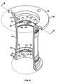
- Cylindrical section 64 extends along the axis C and is coaxial with a second member shown in the form of an upper tubular cylindrical section 70 and a lower tubular cylindrical section 72 joined together by an outer sleeve 74 made integral with the sections 70 and 72 such that the sections 70 and 72 and the sleeve 74 comprise a single rigid structure 76.
- a flange 78 at the upper end of cylindrical section 70 serves as a coupler for coupling the rigid structure 76 of quill 14 to the motor assembly 20, through upper shaft 16 and air bearing 18.
- a coupling arrangement couples the cylindrical section 64 with the upper and lower cylindrical sections 70 and 72 such that there is provided a maximum resistance to relative rotational movement between the cylindrical section 64 and the upper and lower cylindrical sections 70 and 72, while providing minimal resistance to relative axial movement between the cylindrical section 64 and the upper and lower cylindrical sections 70 and 72.
- an upper suspension system 80 couples the upper end 82 of section 64 with the confronting lower end 84 of the upper section 70
- a lower suspension system 90 couples the lower end 92 of section 64 with the confronting upper end 94 of the lower section 72.
- section 64 is suspended within the rigid structure 76, coaxial with the cylindrical sections 70 and 72.
- cylindrical sections 64, 70 and 72 are parts of a one-piece, unitary tubular member shown at 98 in FIGS. 4 and 5 .
- Each suspension system 80 and 90 includes a plurality of suspension elements shown in the form of leaf springs 100 oriented for transmitting torque from the upper and lower cylindrical sections 70 and 72, respectively, to the cylindrical section 64 with maximum resistance to relative rotational displacement between the cylindrical section 64 and the upper and lower cylindrical sections 70 and 72 about axis C, and with minimum resistance to relative axial displacement between the cylindrical section 64 and the upper and lower cylindrical sections 70 and 72 along axis C, at least within a prescribed range of relative axial displacement.
- leaf springs 100 lie in radial planes R normal to axis C and are spaced circumferentially from one another around the axis C. Placement of the essentially flat leaf springs 100 in radial planes R provides rigidity in circumferential directions for resisting relative displacement between section 64 and sections 70 and 72 in circumferential directions, while permitting highly compliant relative axial displacements, in directions normal to radial planes R.
- leaf springs 100 are arranged in stacks 110 of juxtaposed leaf springs 100, the stacks 110 being spaced circumferentially from one another in a symmetrical pattern around the axis C to establish a balanced array of leaf springs 100 around axis C.
- the single tubular member 98 is constructed of relatively rigid material, such as steel or titanium, with suspension systems 80 and 90 formed unitary with sections 64, 70 and 72 by cutting sets of slots 114, 116 and 118 between the confronting ends 82, 84 and 92, 94 to establish at least two circumferentially overlapping leaf springs 100 in each stack 110.
- the sets of slots 114, 116 and 118 are spaced apart axially, and the slots 114, 116 and 118 of each set are spaced apart circumferentially by angles A of 90°.
- the set of slots 116 is rotated at an angle B of 45° relative to the sets of slots 114 and 118 to establish the circumferentially overlapping arrangement of leaf springs 100 in each stack 110.
- the leaf springs 100 are thick enough in axial directions to act as rigid columns in circumferential directions for resisting relative displacement between section 64 and sections 70 and 72 in circumferential directions. However, the leaf springs 100 are thin enough in axial directions to be quite flexible and highly compliant in axial directions, enabling relative axial displacement with minimal resistance.
- an axial position sensor in the form of a proximity transducer 120 provides information pertaining to the axial displacement of section 64 relative to sections 70 and 72.
- Transducer 120 includes a first transducer element 122 fixed within upper section 70 and a second transducer element 124 affixed within section 64, through post 62, proximate first transducer element 122.
- Information pertaining to relative axial displacement between section 64 and section 70 is conducted, in the form of axial position information, via a conductor 126, from the first transducer element 124 to a transmitter circuit board in the form of a disk 128 placed within an upper portion 130 of housing 12 and secured to the central shaft 22 for rotation with the central shaft 22.
- a receptor circuit board 132 is fixed within the upper portion 130 of housing 12, is stationary, and is juxtaposed with and in close proximity to the disk 128 and receives the axial position information for delivery to an external processor 140, in a manner set forth in detail below.
- the construction of quill 14, as described above, enables an accurate determination of axial displacements and, consequently, axial position over a wider range for the ready accommodation of an extended variety of materials to be tested.
- a rotational position sensor in the form of a transducer 150 provides information pertaining to the rotational displacement of the platen 34 relative to the table 36 and provides a measurement of the strain in specimen 50, as set forth in detail in the aforesaid patent no. 4,501,155 , which information is delivered to processor 140.
- a temperature sensor in the form of a thermistor 160 is placed in platen 34 in juxtaposition with and in close proximity to specimen 50 and provides information pertaining to the temperature of the specimen 50 itself during measurement of the axial and rotational displacements set forth above.
- the specimen temperature information is conducted, via a conductor 162, from the thermistor 160 to the transmitter circuit board provided in the form of disk 128.
- the receptor circuit board 132 receives the temperature information for delivery to the processor 140, all as discussed in greater detail below.
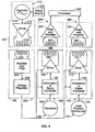
- axial position information from transducer 120 is conducted, via conductor 126, to an axial position information signal transmitter circuit 170 carried by movable disk 128.
- An axial position information signal receptor circuit 180 is carried by stationary receptor circuit board 132.
- An isolator arrangement includes a gap 186 between the disk 128 and the receptor circuit board 132 for providing both mechanical and electrical isolation between the disk 128 and the receptor circuit board 132.
- the axial position information signal is transferred from the axial position information signal transmitter circuit 170 to the axial position information signal receptor circuit 180 by an information transfer system which maintains mechanical and electrical isolation and assures the desired accuracy in the measurement of axial displacement.
- the information transfer system accomplishes the transfer of the axial position information by an induction arrangement.
- axial position information signal transmitter circuit 170 includes an information-to-signal converter 172 for converting the information received from transducer 120 into a corresponding axial position information signal, a signal driver 174 and an axial position information signal primary coil 176, all carried by the disk 128.
- Axial position information signal receptor circuit 180 includes a secondary coil 182 and a high pass filter and amplifier 184.
- the gap 186 establishes a transformer air gap between the primary coil 176 and the secondary coil 182.
- the axial position information signal is passed by induction from the primary coil 176 to the secondary coil 182 so as to maintain mechanical and electrical isolation and assure the desired accuracy.
- the high pass filter and amplifier 184 then derives the axial position information from the axial position information signal and delivers the axial position information to external processor 140.
- specimen temperature information is transferred by an information transfer system which maintains mechanical and electrical isolation and assures the desired accuracy in the measurement of temperature of the specimen 50.
- specimen temperature information from thermistor 160 is conducted, via conductor 162, to a specimen temperature information signal transmitter circuit 190 carried by movable disk 128.
- Specimen temperature information signal transmitter circuit 190 includes a signal converter 192 for converting the specimen temperature information received from thermistor 160 into a specimen temperature information signal, a signal driver 194 and a specimen temperature signal primary coil 196, all carried by the disk 128.
- a specimen temperature information signal receptor circuit 200 is carried by receptor circuit board 132 and includes a secondary coil 202 and a high pass filter and amplifier 204.
- gap 186 provides both mechanical and electrical isolation between the disk 128 and the receptor circuit board 132, and a transformer air gap between the primary coil 196 and the secondary coil 202.
- the specimen temperature information signal is passed by induction from the primary coil 196 to the secondary coil 202 so as to maintain mechanical and electrical isolation and assure the desired accuracy.
- the high pass filter and amplifier 204 then derives the specimen temperature information from the specimen temperature information signal and delivers the specimen temperature information to external processor 140.
- a DC power source 210 supplies power to a power source circuit 212 carried by the receptor circuit board 132.
- the power source circuit 212 includes an oscillator 214, a power driver 216, and a power source primary coil 218.
- a power supply circuit 220 is carried by the disk 128 and includes a power supply secondary coil 222 juxtaposed with the power source secondary coil 216 in an induction arrangement for receiving power from the power source primary coil 216 by induction.
- Power supply secondary coil 222 is coupled to a rectifier and filter 224 for delivering DC power through a voltage regulator 226 to the axial position information signal transmitter circuit 170 and to the specimen temperature signal transmitter circuit 190.
- the arrangement provided by the signal transmitter circuits 170 and 190, and the signal receptor circuits 180 and 200, together with the gap 186, enables information pertaining to the measurement of test parameters which determine rheological characteristics of the specimen 50 to be obtained in close proximity to the site where the information is generated and to be delivered to processor 140 without any mechanical or electrical connection which otherwise could interfere with unfettered circumferential displacement or axial displacement corresponding to the strain induced in the specimen 50 during the testing procedure.
- Placement of thermistor 160 within the moving platen 34 allows temperature measurement to be accomplished proximate the site where temperature information is generated, enabling a direct reading of temperature for enhanced accuracy, without the need for extrapolation or computations to derive an actual temperature, as well as quicker response.
- the delivery of information and power through the above-described transfer systems requires electrical isolation of each signal from the others in order to avoid corruption of the individual signals.
- the required isolation can be accomplished by transmitting each signal by means of a given frequency range, assigning a different range of frequencies to each signal and employing filters to isolate the signals.
- the power circuits 212 and 220 could operate at 50KHz, while the temperature signal circuits 190 and 200 would operate at 500KHz and the axial position information signal circuits 170 and 180 would operate at 5MHz.
- isolation is accomplished readily with simple filters placed in the receptor circuits, as illustrated at 184 and 204 in FIG. 9 .
- Other arrangements utilizing time division multiplexing of binary information, alternating frequencies, or the widths of alternating pulses are feasible.
- each transfer system comprises an induction arrangement
- alternate arrangements are available for accomplishing the transfer of position and temperature information, as well as power.
- Such arrangements include optical systems in which LEDs are modulated to transmit information signals, and capacitance systems in which information signals are transmitted by capacitance coupling.
- Each of these systems enables the direct measurement of displacements and temperatures utilizing powered measuring sensors placed in moving components of a rheometer for enhanced accuracy and quick response through the ability to read directly the test parameters being measured in close proximity to the site where the desired information is being generated.
- the present invention attains all of the objects and advantages summarized above, namely: Provides an improvement in an advanced rheometer capable of performing a complete range of steady, dynamic and transient rheological analyses on sample materials ranging from low viscosity fluids, dispersions and gels to high viscosity polymer melts; enables the accomplishment of rheological testing in less time, with increased accuracy and across a wider range of performance specifications than heretofore available; raises the overall quality of measurements attained with a rheometer; accomplishes normal displacement measurements and temperature measurements in rheological test specimens with increased ease and greater accuracy; assures increased control over measurements in rheological test specimens for greater accuracy; enables simultaneous testing for a wide range of simultaneous analyses; accommodates a wide range of environmental conditions with minimal requirements at testing sites; enables direct readings of test parameters being measured, through powered electronic systems having sensors placed in moving component parts of a rheometer, in close proximity to sites where the desired test information is generated; provides increased reliability for exemplary performance
Landscapes
- Physics & Mathematics (AREA)
- Health & Medical Sciences (AREA)
- Life Sciences & Earth Sciences (AREA)
- Chemical & Material Sciences (AREA)
- Analytical Chemistry (AREA)
- Biochemistry (AREA)
- General Health & Medical Sciences (AREA)
- General Physics & Mathematics (AREA)
- Immunology (AREA)
- Pathology (AREA)
- Investigating Strength Of Materials By Application Of Mechanical Stress (AREA)
- Measurement Of Length, Angles, Or The Like Using Electric Or Magnetic Means (AREA)
Claims (18)
- Rheometer, bei dem eine Belastung in einem Probekörper bewirkt wird, um einen Prüfparameter in dem Probekörper zu messen, das aufweist:einen Sensor (120; 160) für Prüfparameterinformation in Nebeneinanderlage in enger Nähe zu dem Probekörper (50), um Information zur Verfügung zu stellen, die zu dem Prüfparameter des Probekörpers (50) gehört;eine Sendeschaltung (170; 190) für die Prüfparameterinformation zum Empfangen von Prüfparameterinformation von dem Sensor (120; 160) für Prüfparameterinformation;wobei der Sensor (120; 160) für Prüfparameterinformation und die Sendeschaltung (170; 190) für Prüfparameterinformation durch Bewegungen bewegbar sind, die der Belastung entsprechen, welche in dem Probekörper (50) erzeugt wird;eine Empfängerschaltung (180; 200) für Prüfparameterinformation, in Nebeneinandlage zu der Sendeschaltung (170; 190) für Prüfparameterinformation und an einem stationären Ort (132) in Bezug auf die Sendeschaltung (170; 190) für Prüfparameterinformation angeordnet;eine Isolatoranordnung (186), die die stationäre Empfängerschaltung (180; 200) für Prüfparameterinformation mechanisch und elektrisch von der bewegbaren Sendeschaltung (170; 190) für Prüfparameterinformation isoliert; undein Übertragungssystem (176, 182; 196; 202) für Prüfparameterinformation zum Überführen von Prüfparameterinformation von der bewegbaren Sendeschaltung (170; 190) für Prüfparameterinformation über die Isolatoranordnung (186) zu der stationären Empfängerschaltung (180; 200) für Prüfparameterinformation ohne eine direkte mechanische oder elektrische Verbindung zwischen der bewegbaren Sendeschaltung (170; 190) für Prüfparameterinformation und der stationären Empfängerschaltung (180; 200) für Prüfparameterinformation.
- Rheometer nach Anspruch 1, bei dem das Übertragungssystem (176, 182; 196, 202) für Prüfparameterinformation eine Induktionsanordnung aufweist, welche eine primäre Induktionsspule (176; 196) in der Sendeschaltung (170; 190) für Prüfparameterinformation und eine sekundäre Induktionsspule (182; 202) in der Empfängerschaltung (180; 200) für Prüfparameterinformation umfasst in Nebeneinanderlage zu der primären Induktionsspule (176; 196), um durch Induktion von Prüfparameterinformation von der primären Induktionsspule (176, 196) zu empfangen.
- Rheometer nach einem der Ansprüche 1 oder 2, das umfasst:eine Energiequelle (210);eine Energiesendeschaltung (212), die an einem stationären Ort (132) in Bezug zu der Sendeschaltung (170; 190) für Prüfparameterinformation angeordnet und mit der Energiequelle (210) verbunden ist;eine Energieempfängerschaltung (220), die neben der Energiesendeschaltung (212) zum Empfangen von Energie aus der Energiesendeschaltung (212) angeordnet ist, wobei die Energieempfängerschaltung (220) durch Bewegungen bewegbar ist, die den Bewegungen der Sendeschaltung (170; 190) für Prüfparameterinformation entsprechen, und mit der Sendeschaltung (170; 190) für Prüfparameterinformation zum Liefern von Energie an die Sendeschaltung (170; 190) für Prüfparameterinformation verbunden ist;eine Isolatoranordnung (186), welche die stationäre Energiesendeschaltung (212) mechanisch und elektrisch von der bewegbaren Energieempfängerschaltung (220) isoliert; undein Energieübertragungssystem (214, 216, 218, 222, 224, 226) zum Überführen von Energie aus der stationären Energiesendeschaltung (212) über die Isolatoranordnung (186) zu der bewegbaren Energieempfängerschaltung (220) ohne eine direkte mechanische oder elektrische Verbindung zwischen der stationären Energiesendeschaltung (212) und der bewegbaren Energieempfängerschaltung (220).
- Rheometer nach Anspruch 3, bei dem das Energieübertragungssystem (214, 216, 218, 222, 224, 226) eine Induktionsanordnung aufweist, welche eine primäre Induktionsspule (218) in der Energiesendeschaltung (212) und eine sekundäre Induktionsspule (222) in der Energieempfängerschaltung (220) umfasst, in Nebeneinanderlage zu der primären Induktionsspule (228), um durch Induktion Energie aus der primären Induktionsspule (218) zu empfangen.
- Rheometer nach einem der Ansprüche 1 bis 4, bei dem der gemessene Prüfparameter die Temperatur ist.
- Rheometer nach einem der Ansprüche 1 bis 5, bei dem der Probekörper (50) einem Drehmoment um eine gegebene Achse (C) in dem Rheometer (10) ausgesetzt wird, um eine Belastung in dem Probekörper (50) um die gegebene Achse (C) auszuüben, das aufweist:ein erstes Element (64),einen ersten Koppler (30) zum Koppeln des ersten Elementes (64) mit dem Probekörper (50), während der Probekörper (50) einem angelegten Drehmoment ausgesetzt ist;ein zweites Element (76);einen zweiten Koppler (78) zum Koppeln des zweiten Elementes (76) mit einer Motoranordnung (20) zum Übertragen von Drehmoment von der Motoranordnung (20) zu dem zweiten Element (76); undeine Kopplungsanordnung (80, 90), welche das erste Element (64) mit dem zweiten Element (76) für die Bewegung des zweiten Elementes (76) in Umfangsrichtung um die gegebene Achse (C), entsprechend der Belastung, die in dem Probekörper (70) um die gegebene Achse (C) hervorgerufen wird, und für die relative axiale Verlagerung zwischen dem ersten Element (64) und dem zweiten Element (76) entlang der gegebenen Achse (C) koppelt,wobei der gemessene Prüfparameter die axiale Position des ersten Elementes (64) in Bezug auf das zweite Element (76) ist.
- Rheometer nach Anspruch 6, das umfasst:einen Sensor (160) für Temperaturinformation des Probekörpers zum Liefern von Information, welche zu der Temperatur des Probekörpers gehört;eine Sendeschaltung (190) für Information über eine Probekörpertemperatur zum Empfangen von Information über eine Probekörpertemperatur von dem Sensor (160) für Information über die Temperatur des Probekörpers, wobei die Sendeschaltung (190) für Information über die Temperatur des Probekörpers durch Bewegungen bewegbar ist, die der Bewegung des zweiten Elementes (76) in der Umfangsrichtung um die gegebene Achse (C) entsprechen;eine Empfangsschaltung (200) für Information über die Temperatur des Probekörpers in Nebeneinanderlage zu der Sendeschaltung (190) für Information über die Temperatur des Probekörpers und an einem stationären Ort (132) in Bezug auf die Sendeschaltung (190) für Information über die Temperatur des Probekörpers angeordnet;eine Isolatoranordnung (186), welche die stationäre Empfangsschaltung (200) für Information über die Temperatur des Probekörpers mechanisch und elektrisch von der bewegbaren Sendeschaltung (190) für Information über die Temperatur eines Probekörpers isoliert; undein Übertragungssystem (196, 202) für Temperaturinformation zum Leiten der Information über die Temperatur eines Probekörpers von der bewegbaren Sendeschaltung (190) für Information über die Temperatur eines Probekörpers über die Isolatoranordnung (186) zu der stationären Empfangsschaltung (200) für Information über die Temperatur eines Probekörpers ohne eine direkte mechanische oder elektrische Verbindung zwischen der bewegbaren Sendeschaltung (190) für Information über die Temperatur eines Probekörpers und der stationären Empfangsschaltung (200) für Information über die Temperatur eines Probekörpers.
- Rheometer nach Anspruch 7, bei das Übertragungssystem (196, 202) für Temperaturinformation eine Induktionsanordnung aufweist, die eine primäre Induktionsspule (196) in der Sendeschaltung (190) für Information über die Temperatur eines Probekörpers und eine sekundäre Induktionsspule (202) in der Empfangsschaltung (200) für Information über die Temperatur eines Probekörpers umfasst, in Nebeneinanderlage zu der primären Induktionsspule (196), um durch Induktion Information über die Temperatur eines Probekörpers von der primären Induktionsspule (196) zu empfangen.
- Rheometer nach einem der Ansprüche 1 bis 8, bei dem Isolatoranordnung einen Luftspalt (186) zwischen der primären Induktionsspule (176; 196) und der sekundären Induktionsspule (182; 202) umfasst.
- Rheometer nach einem der Ansprüche 6 bis 9, bei dem die Kopplungsanordnung (80, 90) eine Vielzahl von federnden Elementen (100) umfasst, die in der Umfangsrichtung um die gegebene Achse (C) im Wesentlichen starr und in axialer Richtung entlang der gegebenen Achse (C) stark nachgiebig sind, wobei die federnden Elemente (100) zum Übertragen von Drehmoment von dem zweiten Element (76) auf das erste Element (64) ausgerichtet sind, mit maximalem Widerstand gegen die relative Drehverlagerung zwischen dem ersten Element (64) und dem zweiten Element (76) um die gegebene Achse (C) und mit minimalem Widerstand gegen eine relative axiale Verlagerung zwischen dem ersten Element (64) und dem zweiten Element (76) entlang der gegebenen Achse (C), innerhalb des vorgeschriebenen Bereiches der axialen Verlagerung.
- Rheometer nach Anspruch 10, bei dem die Vielzahl der federnden Elemente (100) eine erste Anzahl federnder Elemente (100) und eine zweite Anzahl federnder Elemente (100) umfasst, wobei die zweite Anzahl federnder Elemente (100) axial von der ersten Anzahl federnder Elemente (100) beabstandet ist und die ersten und die zweiten Elemente (64, 76) axial zwischen der ersten und der zweiten Anzahl federnder Elemente (100) zusammen gekoppelt sind.
- Rheometer nach Anspruch 11, bei dem:das erste Element (64) ein erstes Ende (82) und ein zweites Ende (92) umfasst, wobei das zweite Ende (92) axial von dem ersten Ende (82) beabstandet ist, mit einem festen axialen Abstand von dem ersten Ende (82);das zweite Element (76) ein entsprechendes erstes Ende (84) und ein entsprechendes zweites Ende (94) umfasst;die erste Anzahl federnder Elemente (100) zwischen dem ersten Ende (82) des ersten Elementes (64) und dem entsprechenden ersten Ende (84) des zweiten Elements (76) angeordnet ist; unddie zweite Anzahl federnder Elemente (100) zwischen dem zweiten Ende (92) des ersten Elements (64) und dem entsprechenden zweiten Ende (94) des zweiten Elements (76) angeordnet ist;so dass die federnden Elemente (100) das zweite Element (76) mit dem ersten Element (64) mit maximalem Widerstand gegen die relative Drehverlagerung zwischen dem ersten Element (64) und dem zweiten Element (76) in Umfangsrichtung um die gegebene Achse (C) und mit minimalem Widerstand gegen die relative axiale Verlagerung zwischen dem ersten Element (64) und dem zweiten Element (76) entlang der gegebenen Achse (C) koppeln, innerhalb des vorbeschriebenen Bereiches axialer Verlagerung.
- Rheometer nach einem der Ansprüche 10 bis 12, bei dem die Vielzahl der federnden Elemente Blattfederelemente (100) umfassen, die sich umfangsmäßig um die gegebene Achse (C) erstrecken und umfangsmäßig voneinander beabstandet sind, um für Steifigkeit in Umfangsrichtung um die gegebene Achse (C) und Flexibilität in axialer Richtung entlang der gegebenen Achse (C) zu sorgen.
- Rheometer nach Anspruch 13, bei dem die Blattfederelemente (100) in einem symmetrischen Muster um die gegebene Achse (C) angeordnet sind.
- Rheometer nach Anspruch 14, bei dem die Blattfederelemente (110) in umfangsmäßigen beabstandeten sich in axialer Richtung erstreckenden Stapeln (110) von axial nebeneinander liegenden Blattfederelementen (100) angeordnet sind.
- Rheometer nach Anspruch 135 bei dem jeder Stapel der axialen Stapel wenigstens zwei umfangsmäßig überlappende Federelemente umfasst, die axial innerhalb des Stapels beabstandet sind.
- Rheometer nach Anspruch 16, bei dem das erste Element (64) einen ersten rohrförmigen zylindrischen Abschnitt umfasst, das zweite Element (76) einen zweiten rohrförmigen zylindrischen Abschnitt (70, 72) umfasst und die umfangsmäßig beabstandeten Stapel zwischen dem ersten rohrförmigen zylindrischen Abschnitt und dem zweiten rohrförmigen zylindrischen Abschnitt (70, 72) angeordnet sind.
- Rheometer nach Anspruch 17, bei dem die Stapel (110) einheitlich mit dem ersten und dem zweiten rohrförmigen zylindrischen Abschnitt (64, 70, 72) ausgebildet sind.
Applications Claiming Priority (2)
| Application Number | Priority Date | Filing Date | Title |
|---|---|---|---|
| US10/459,056 US6931915B2 (en) | 2003-06-10 | 2003-06-10 | Wide range dynamic rheometer |
| PCT/US2004/017880 WO2004111607A2 (en) | 2003-06-10 | 2004-06-09 | Wide range dynamic rheometer |
Publications (3)
| Publication Number | Publication Date |
|---|---|
| EP1631816A2 EP1631816A2 (de) | 2006-03-08 |
| EP1631816A4 EP1631816A4 (de) | 2008-07-23 |
| EP1631816B1 true EP1631816B1 (de) | 2011-10-26 |
Family
ID=33510721
Family Applications (1)
| Application Number | Title | Priority Date | Filing Date |
|---|---|---|---|
| EP04754478A Revoked EP1631816B1 (de) | 2003-06-10 | 2004-06-09 | Dynamisches rheometer mit weitem bereich |
Country Status (4)
| Country | Link |
|---|---|
| US (1) | US6931915B2 (de) |
| EP (1) | EP1631816B1 (de) |
| JP (1) | JP4256424B2 (de) |
| WO (1) | WO2004111607A2 (de) |
Families Citing this family (8)
| Publication number | Priority date | Publication date | Assignee | Title |
|---|---|---|---|---|
| US7591950B2 (en) * | 2004-11-02 | 2009-09-22 | Siemens Water Technologies Corp. | Submerged cross-flow filtration |
| US20080315897A1 (en) * | 2007-06-22 | 2008-12-25 | Neuro Vasx, Inc. | Induction coil resistance tester |
| US20090211343A1 (en) * | 2008-01-17 | 2009-08-27 | David Zumbrunnen | In-situ structuring rheometer based on chaotic advection |
| DE102010050973B4 (de) | 2010-11-10 | 2019-01-24 | Thermo Electron (Karlsruhe) Gmbh | Rheometer oder Viskosimeter |
| KR101719412B1 (ko) * | 2015-04-30 | 2017-03-23 | 서울대학교산학협력단 | 레오미터용 정밀 토션블럭 |
| JP1652289S (de) * | 2019-06-21 | 2020-02-03 | ||
| CN114556078B (zh) | 2019-10-15 | 2025-07-15 | Ta仪器-沃特世有限责任公司 | 用于对具有可变体积的材料进行流变测量的转子 |
| WO2021154896A1 (en) * | 2020-01-27 | 2021-08-05 | Logilube, LLC | Methods and devices for monitoring machine fluids |
Family Cites Families (5)
| Publication number | Priority date | Publication date | Assignee | Title |
|---|---|---|---|---|
| US4501155A (en) * | 1983-06-29 | 1985-02-26 | Rheometrics, Inc. | Compensated rheometer |
| US4601195A (en) * | 1985-04-11 | 1986-07-22 | Rheometrics, Inc. | Apparatus and method for measuring viscoelastic properties of materials |
| US5520042A (en) * | 1995-06-19 | 1996-05-28 | Rheometric Scientific | Apparatus and method for the simultaneous measurement of rheological and thermal characteristics of materials and measuring cell therefor |
| US5708197A (en) | 1996-05-07 | 1998-01-13 | Polymer Processing Institute | Helical barrel rheometer |
| AT409304B (de) | 1999-09-24 | 2002-07-25 | Anton Paar Gmbh | Rotationsrheometer |
-
2003
- 2003-06-10 US US10/459,056 patent/US6931915B2/en not_active Expired - Lifetime
-
2004
- 2004-06-09 WO PCT/US2004/017880 patent/WO2004111607A2/en not_active Ceased
- 2004-06-09 EP EP04754478A patent/EP1631816B1/de not_active Revoked
- 2004-06-09 JP JP2006533573A patent/JP4256424B2/ja not_active Expired - Fee Related
Also Published As
| Publication number | Publication date |
|---|---|
| JP2007503596A (ja) | 2007-02-22 |
| EP1631816A4 (de) | 2008-07-23 |
| US20040250605A1 (en) | 2004-12-16 |
| EP1631816A2 (de) | 2006-03-08 |
| JP4256424B2 (ja) | 2009-04-22 |
| US6931915B2 (en) | 2005-08-23 |
| WO2004111607A3 (en) | 2005-06-23 |
| WO2004111607A2 (en) | 2004-12-23 |
Similar Documents
| Publication | Publication Date | Title |
|---|---|---|
| JP6504847B2 (ja) | 試料の測定データを決定する方法およびレオメータ | |
| CA1259817A (en) | Apparatus and method for measuring viscoelastic properties of materials | |
| US6418776B1 (en) | Method and apparatus for measuring friction and wear characteristics of materials | |
| EP1631816B1 (de) | Dynamisches rheometer mit weitem bereich | |
| CA2758088C (en) | Non-contact stress measuring device | |
| CA1217952A (en) | Compensated rheometer | |
| US3699808A (en) | Dynamic testing device for visco-elastic materials | |
| US10788476B2 (en) | Friction testing apparatus and method | |
| CN102713561A (zh) | 旋转式粘度计 | |
| US9513202B2 (en) | Viscometer | |
| WO1996016324A1 (en) | Pressurized viscometer | |
| US20120260723A1 (en) | Low friction rheometer | |
| JP2022532253A (ja) | 機械システムの健全性及び性能を監視するための装置及び方法 | |
| US2580395A (en) | Torque dynamometer | |
| Franck et al. | Understanding instrument compliance correction in oscillation | |
| WO1990004161A1 (en) | Rheometer calibration | |
| US20250003851A1 (en) | Rheometer for simultaneous rheological and electrical measurements | |
| GB555595A (en) | Improvements in and relating to apparatus for measuring the phase and amplitude of mechanical vibrations | |
| EP4735863A1 (de) | Messsysteme für rheologie- und dielektrische spektroskopie | |
| SU576552A1 (ru) | Устройство дл контрол соосности магнитных и геомертических осей | |
| WO1988003263A1 (en) | Rheometer | |
| CN121430957A (zh) | 一种多螺旋弹簧系统径向刚度测试装置及测试方法 | |
| CN112326487A (zh) | 一种导电刷丝载流摩擦试验装置和试验方法 | |
| Jerrard et al. | Apparatus for the Study of the Dielectric Properties of Macromolecular Solutions under Flow | |
| JPH04109420A (ja) | 回転磁気ヘッドの突出量調整/検査方法及びそのための調整/検査装置 |
Legal Events
| Date | Code | Title | Description |
|---|---|---|---|
| PUAI | Public reference made under article 153(3) epc to a published international application that has entered the european phase |
Free format text: ORIGINAL CODE: 0009012 |
|
| 17P | Request for examination filed |
Effective date: 20051206 |
|
| AK | Designated contracting states |
Kind code of ref document: A2 Designated state(s): DE FR GB |
|
| DAX | Request for extension of the european patent (deleted) | ||
| RBV | Designated contracting states (corrected) |
Designated state(s): DE FR GB |
|
| RIN1 | Information on inventor provided before grant (corrected) |
Inventor name: BERTING, JOHN, P. Inventor name: GARRITANO, RONALD, F. Inventor name: MODE, PAUL, G. |
|
| RIC1 | Information provided on ipc code assigned before grant |
Ipc: G01N 11/00 20060101AFI20070615BHEP |
|
| A4 | Supplementary search report drawn up and despatched |
Effective date: 20080623 |
|
| 17Q | First examination report despatched |
Effective date: 20110204 |
|
| GRAP | Despatch of communication of intention to grant a patent |
Free format text: ORIGINAL CODE: EPIDOSNIGR1 |
|
| GRAS | Grant fee paid |
Free format text: ORIGINAL CODE: EPIDOSNIGR3 |
|
| GRAA | (expected) grant |
Free format text: ORIGINAL CODE: 0009210 |
|
| AK | Designated contracting states |
Kind code of ref document: B1 Designated state(s): DE FR GB |
|
| REG | Reference to a national code |
Ref country code: GB Ref legal event code: FG4D |
|
| REG | Reference to a national code |
Ref country code: DE Ref legal event code: R096 Ref document number: 602004035024 Country of ref document: DE Effective date: 20120119 |
|
| PLBI | Opposition filed |
Free format text: ORIGINAL CODE: 0009260 |
|
| PLAX | Notice of opposition and request to file observation + time limit sent |
Free format text: ORIGINAL CODE: EPIDOSNOBS2 |
|
| 26 | Opposition filed |
Opponent name: ANTON PAAR GMBH Effective date: 20120725 |
|
| PLAF | Information modified related to communication of a notice of opposition and request to file observations + time limit |
Free format text: ORIGINAL CODE: EPIDOSCOBS2 |
|
| RAP2 | Party data changed (patent owner data changed or rights of a patent transferred) |
Owner name: WATERS TECHNOLOGIES CORPORATION |
|
| REG | Reference to a national code |
Ref country code: DE Ref legal event code: R026 Ref document number: 602004035024 Country of ref document: DE Effective date: 20120725 |
|
| PLBB | Reply of patent proprietor to notice(s) of opposition received |
Free format text: ORIGINAL CODE: EPIDOSNOBS3 |
|
| RDAF | Communication despatched that patent is revoked |
Free format text: ORIGINAL CODE: EPIDOSNREV1 |
|
| APBM | Appeal reference recorded |
Free format text: ORIGINAL CODE: EPIDOSNREFNO |
|
| APBP | Date of receipt of notice of appeal recorded |
Free format text: ORIGINAL CODE: EPIDOSNNOA2O |
|
| APAH | Appeal reference modified |
Free format text: ORIGINAL CODE: EPIDOSCREFNO |
|
| APBQ | Date of receipt of statement of grounds of appeal recorded |
Free format text: ORIGINAL CODE: EPIDOSNNOA3O |
|
| REG | Reference to a national code |
Ref country code: FR Ref legal event code: PLFP Year of fee payment: 13 |
|
| PGFP | Annual fee paid to national office [announced via postgrant information from national office to epo] |
Ref country code: GB Payment date: 20160627 Year of fee payment: 13 |
|
| PGFP | Annual fee paid to national office [announced via postgrant information from national office to epo] |
Ref country code: FR Payment date: 20160628 Year of fee payment: 13 |
|
| PGFP | Annual fee paid to national office [announced via postgrant information from national office to epo] |
Ref country code: DE Payment date: 20160628 Year of fee payment: 13 |
|
| REG | Reference to a national code |
Ref country code: DE Ref legal event code: R064 Ref document number: 602004035024 Country of ref document: DE Ref country code: DE Ref legal event code: R103 Ref document number: 602004035024 Country of ref document: DE |
|
| APBU | Appeal procedure closed |
Free format text: ORIGINAL CODE: EPIDOSNNOA9O |
|
| RDAG | Patent revoked |
Free format text: ORIGINAL CODE: 0009271 |
|
| STAA | Information on the status of an ep patent application or granted ep patent |
Free format text: STATUS: PATENT REVOKED |
|
| 27W | Patent revoked |
Effective date: 20161216 |
|
| GBPR | Gb: patent revoked under art. 102 of the ep convention designating the uk as contracting state |
Effective date: 20161216 |