EP1631417B1 - Turbinenschaufel - Google Patents
Turbinenschaufel Download PDFInfo
- Publication number
- EP1631417B1 EP1631417B1 EP04735684A EP04735684A EP1631417B1 EP 1631417 B1 EP1631417 B1 EP 1631417B1 EP 04735684 A EP04735684 A EP 04735684A EP 04735684 A EP04735684 A EP 04735684A EP 1631417 B1 EP1631417 B1 EP 1631417B1
- Authority
- EP
- European Patent Office
- Prior art keywords
- engagement
- face
- engagement member
- turbine blade
- platform
- Prior art date
- Legal status (The legal status is an assumption and is not a legal conclusion. Google has not performed a legal analysis and makes no representation as to the accuracy of the status listed.)
- Expired - Lifetime
Links
Images


Classifications
-
- F—MECHANICAL ENGINEERING; LIGHTING; HEATING; WEAPONS; BLASTING
- F01—MACHINES OR ENGINES IN GENERAL; ENGINE PLANTS IN GENERAL; STEAM ENGINES
- F01D—NON-POSITIVE DISPLACEMENT MACHINES OR ENGINES, e.g. STEAM TURBINES
- F01D5/00—Blades; Blade-carrying members; Heating, heat-insulating, cooling or antivibration means on the blades or the members
- F01D5/12—Blades
- F01D5/14—Form or construction
-
- F—MECHANICAL ENGINEERING; LIGHTING; HEATING; WEAPONS; BLASTING
- F01—MACHINES OR ENGINES IN GENERAL; ENGINE PLANTS IN GENERAL; STEAM ENGINES
- F01D—NON-POSITIVE DISPLACEMENT MACHINES OR ENGINES, e.g. STEAM TURBINES
- F01D5/00—Blades; Blade-carrying members; Heating, heat-insulating, cooling or antivibration means on the blades or the members
- F01D5/30—Fixing blades to rotors; Blade roots ; Blade spacers
- F01D5/3007—Fixing blades to rotors; Blade roots ; Blade spacers of axial insertion type
-
- F—MECHANICAL ENGINEERING; LIGHTING; HEATING; WEAPONS; BLASTING
- F05—INDEXING SCHEMES RELATING TO ENGINES OR PUMPS IN VARIOUS SUBCLASSES OF CLASSES F01-F04
- F05D—INDEXING SCHEME FOR ASPECTS RELATING TO NON-POSITIVE-DISPLACEMENT MACHINES OR ENGINES, GAS-TURBINES OR JET-PROPULSION PLANTS
- F05D2230/00—Manufacture
- F05D2230/10—Manufacture by removing material
-
- F—MECHANICAL ENGINEERING; LIGHTING; HEATING; WEAPONS; BLASTING
- F05—INDEXING SCHEMES RELATING TO ENGINES OR PUMPS IN VARIOUS SUBCLASSES OF CLASSES F01-F04
- F05D—INDEXING SCHEME FOR ASPECTS RELATING TO NON-POSITIVE-DISPLACEMENT MACHINES OR ENGINES, GAS-TURBINES OR JET-PROPULSION PLANTS
- F05D2230/00—Manufacture
- F05D2230/60—Assembly methods
- F05D2230/68—Assembly methods using auxiliary equipment for lifting or holding
Definitions
- the present invention relates to a turbine blade, as per the preamble of claim 1.
- a turbine blade as per the preamble of claim 1.
- An example of such a turbine is disclosed by US 6 017 263 A.
- a typical turbine blade includes a blade airfoil as a blade base, one side of the blade airfoil being a convex suction surface and the other side of the blade being a concave pressure surface.
- a platform is integrally molded on the hub side (at the base end portion) of the blade and recesses are formed respectively on both sides of the platform.
- a front seal fin protruding forward is formed at the front end of the platform and a rear seal fin protruding backward is formed at the back end of the platform.
- a male dovetail is integrally disposed on the hub side (at the base end portion) of the platform, the dovetail has an engagement portion able to engage with a female dovetail of a turbine disk, and the engagement portion is usually formed by grinding, whereby, a jig is used for grinding, and one side of the platform can be engaged against a platform-locating portion of the jig.
- the manufacturing process of the typical turbine blade will be described below.
- the greater part of the turbine blade with the engagement portion remaining unfinished (an unfinished turbine blade) is molded by casting.
- the unfinished turbine blade is located in the jig so as to make the dovetail axial direction perpendicular to the repulsive force due to work-resistance during grinding, by letting the pressure surface of the blade airfoil supported with a support portion of the jig.
- setting of the unfinished turbine blade onto the jig is completed by pressing the pressure surface of the blade airfoil against the location portion by means of a clamp of the jig.
- the turbine blade is finished by forming the engagement portion along the dovetail axial direction by grinding.
- both sides of the platform are angled to the dovetail axial direction of the engagement portion. Consequently, during formation of the engagement portion along the dovetail axial direction by grinding, a component of a force that may cause a displacement of the blade airfoil from the jig is generated. Therefore, there is a problem in that a machining tolerance of the engagement portion is degraded, lowering the quality of the turbine blade, because the unfinished turbine blade is displaced from the jig owing to an increase in the magnitude of the component of a force during grinding.
- the unfinished turbine blade of claim 1 is never displaced from the jig, forming an engagement portion with tight machining tolerance, thus enhancing the quality of the turbine blade.
- a turbine blade to be installed into an engaged member of a turbine disk of an aircraft engine is characterized in that it comprises a blade airfoil, one side of which having a convex suction surface and the other side having a concave pressure surface; a platform integrally molded on the hub side of the blade wherein a recess is formed on one side of the platform; a front seal fin formed protruding forward at the front end of the platform; and a rear seal fin formed protruding backward at the back end of the platform, an engagement member integrally molded on the hub side of the platform wherein the engagement member has a engagement face which is able to be engaged with the engaged member of turbine disk and is formed by grinding, a front engagement member integrally molded in the vicinity of a base portion of the front seal fin wherein the front engagement member has a front engagement face able to engage with a front locating portion of a jig to be used for the grinding, and the front engagement face located back from a virtual plane including one side of the
- the turbine blade is characterized in that the front engagement face and the rear engagement face are respectively configured to be substantially parallel to the longitudinal direction of the engagement member.
- the turbine blade is further characterized in that the spacing between the front edge of the front engagement face and the rear edge of the rear engagement face are configured to be longer than the longitudinal length of the engagement member.
- the turbine blade is further characterized in that the depth that the front engagement face is located back from the virtual plane and the depth that the rear engagement face is located back from the virtual plane are respectively configured to be in a range of less than or equal to 0.7 mm.
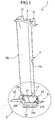
- FIG.1 shows a turbine blade according to an embodiment of the present invention
- Fig.2 is an enlarged view of the arrowed portion II in Fig.1
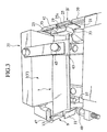
- Fig.3 shows a state where the turbine blade according to the embodiment of the present invention is set on a jig
- Fig.4 is a schematic view of the arrowed portion IV in Fig.3
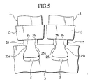
- Fig. 5 shows a state where the turbine blade according to the embodiment of the present invention is installed into a female dovetail of a turbine disk.
- front and rear (or back) refers to right hand side and left hand side in Fig.1 and Fig.2, and refers to left hand side and right hand side in Fig.4.
- the turbine blade 1 relating to the embodiment of the present invention is one to be installed into a female dovetail 5 of a turbine disk 3 of a low-pressure turbine for an aircraft engine and comprises a blade airfoil 7 as a main body of the turbine blade 1.
- One side (the front side in Fig.1) of the blade airfoil 7 is a convex suction surface 7fa and the other side (the back side in Fig.1) of the blade airfoil 7 is a concave pressure surface 7fb.
- a shroud 9 is integrally molded on the tip side (the outer end portion, the upside in Fig.1) of the blade airfoil 7 and the shroud 9 has a couple of seal fins 11, 13.
- a platform 15 is integrally molded on the hub side (the inner end portion, the downside in Fig.1) of the blade airfoil 7, and recesses 17, 19 are formed respectively on both sides (the one side and the other side) the platform 15. Moreover, a front seal fin 21 protruding forward is formed at the front end of the platform, and a rear seal fin 23 protruding backward is formed at the back end of the platform 15. A so-called shank portion is also included in the platform.
- a male dovetail 25 as an engagement member is integrally molded on the hub side of the platform 15 and the male dovetail 25 has an engagement groove (an engagement face) 25s which is able to be engaged with an engaged protrusion (an engaged portion) 5b of the female dovetail 5 as an engaged member, and the engagement groove 25s is formed by grinding.
- a front engagement member 27 is integrally molded within the recess 17 in the vicinity of a base portion of the front seal fin 21 and the front engagement member 27 has a front engagement face 27f. Further, as shown with diagonal lines in Fig. 2, a thin front wall Wf surrounding a front side-edge portion of the front engagement member 27 is integrally molded in the vicinity of the base portion of the front seal fin 21.
- a rear engagement member 29 is integrally molded within the recess 17 in the vicinity of a base portion of the rear seal fin 23 and the rear engagement member 29 has a rear engagement face 29f. Further, as shown with diagonal lines in Fig. 2, a thin rear wall Wr, which surrounds a rear side-edge portion of the rear engagement member 29, is integrally molded in the vicinity of the base portion of the rear seal fin 23.
- the front engagement face 27f of the front engagement member 27 is able to be engaged by a front locator pin 33 of a jig 31 to be used for the grinding
- the rear engagement face 29f of the rear engagement member 29 is able to be engaged against a rear engage pin 35 of the jig 31.
- the front engagement face 27f of the front engagement member 27 and the rear engagement face 29f of the rear engagement member 29 are respectively configured to be located slightly back from a virtual plane VF including one side of the platform 15 and also to be substantially parallel to the dovetail axial direction (longitudinal direction) of the male dovetail 25.
- the distance (depth) of which the front engagement face 27f is located back from the virtual plane VF and the distance (depth) of which the rear engagement face 29f is located back from the virtual plane VF are respectively configured to be in a range of less than or equal to 0.7 mm.
- each of the front engagement face 27f of the front engagement member 27 and the rear engagement face 29f of the rear engagement member 29 has a recess in a range of less than or equal to 0.7 mm.
- the spacing between the front edge of the front engagement face 27f and the rear edge of the rear engagement face 29f are configured to be longer than the length of the male dovetail 25 in the dovetail axial direction.
- An end face of the front wall Wf and an end face of the rear wall Wr are respectively configured to be coplanar-with the-virtual plane VF.
- the jig 31 includes the front locator pin 33 and a rear locator pin 35 as well as a locating roller 37 for locating the suction surface 7fa near the tip of the blade airfoil 7, a locating pin 41 for clipping the male dovetail 25 at the rear side thereof and a clip 39 for clipping the male dovetail 25 at the front side thereof, a clamp 45 for pressing the pressure surface 7fb near the hub of the blade airfoil 7 downward via a rubber pad 43, an engagement roller 47 able to be engaged against the back end of the shroud 9, a contact bolt 49 able to be contacted with the front end of the shroud 9.
- the operation (mainly manufacturing of the turbine blade 1) of an embodiment of the present invention will be described below.
- the greater part of the turbine blade 1, with machining portions of the engagement groove 25s and the shroud 9 remaining unfinished (an unfinished turbine blade 1'), is molded by casting. Since the vicinity of base portion of the front seal fin 21 is configured to be thicker in consideration of the strength of the fin, the front engagement member 27 and the front wall Wf are molded utilizing the thicker portion. Also, since the vicinity of base portion of the rear seal fin 23 is configured to be thicker in consideration of the strength of the fin, the rear engagement member 29 and the rear wall Wr are molded utilizing the thicker portion.
- each of the front engagement face 27f and the rear engagement face 29f has a recess in a range of less than or equal to 0.7 mm, casting defects do not easily occur in the vicinity of the front engagement face 27f and the rear engagement face 29f.
- the machining portion of the shroud 9 is operated by appropriate machining.
- the front engagement face 27f of the front engagement member 27 and the rear engagement face 29f of the rear engagement member 29 are engaged by the front locator pin 33 of the jig 31 and the rear locator pin 35 of the jig 31 respectively, and the suction surface 7fa of the blade airfoil 7 is made to be located with the locating roller 37 of the jig 31.
- the unfinished turbine blade 1' can be located in the jig 31 so as to make the dovetail axial direction perpendicular to the repulsive force due to work-resistance during grinding.
- location of the unfinished turbine blade 1' relative to the jig 31 in the machining direction is also performed by engaging the back end of the shroud 9 with the engagement roller 47 of the jig 31 to make the contact bolt 49 contact with the front end of the shroud 9.
- the male dovetail 25 is located at the rear end of the dovetail 25 with a locating pin 41 of the jig 31, and clipped with a clip 39 at the front end of the dovetail 25, and the pressure surface 7fb near the hub of the blade airfoil 7 is pressed downward with a clamp 45 of the jig 31 via a rubber pad 43.
- the setting of the unfinished turbine blade 1' onto the jig 31 is completed. Since the spacing between the front edge of the front engagement face 27f and the rear edge of the rear engagement face 29f has been configured to be longer than the longitudinal length of the engagement member, the loaded state of the unfinished turbine blade 1' on the jig 31 is further stabilized.
- the manufacturing of the turbine blade 1 is finished by forming the engagement groove 25s along the dovetail axial direction by the grinding. Since the front engagement face 27f of the front engagement member 27 and the rear engagement face 29f of the rear engagement member 29 are respectively configured to be substantially parallel to the dovetail axial direction, only the repulsive force, which is due to work resistance and is perpendicular to the dovetail axial direction, will occur on the front engagement face 27f and the rear engagement face 29f in a case where the engagement groove 25s is formed along the dovetail axial direction by grinding. Therefore, substantially no repulsive force, which displaces the longitudinal direction of the dovetail, will occur.
- the front engagement face 27f of the front engagement member 27 and the rear engagement face 29f of the rear engagement member 29 are respectively configured to be located slightly back from the virtual plane VF including one side of the platform 15. And also, the end face of the front wall Wf and the end face of the rear wall Wr are respectively configured to be coplanar with the virtual plane VF. Therefore, the spacing between adjacent turbine blades 1 will not be widened locally when a number of turbine blades 1 are installed into the turbine disk 3.
- the front engagement member 27 and the front wall Wf are molded utilizing the thicker portion which is configured to be thicker in consideration to the strength of the front seal fin 21, and the rear engagement member 29 and the rear wall Wr are molded utilizing the thicker portion which is configured to be thicker in consideration to the strength of the rear seal fin 23. Therefore, the addition of the -front engagement member 27-, the front wall Wf, the rear engagement member 29 and the rear wall Wr to the components of the turbine blade 1 does not cause any increase in a weight of the turbine blade 1.
- the present invention should not be limited to the description of the above embodiment of the invention, but it can be applicable in various modes through causing the appropriate conversion thereof, for example, an application of the turbine blade 1 to a turbine blade for a high-pressure turbine of the aircraft engine, etc.
Landscapes
- Engineering & Computer Science (AREA)
- Mechanical Engineering (AREA)
- General Engineering & Computer Science (AREA)
- Turbine Rotor Nozzle Sealing (AREA)
Claims (5)
- Turbinenschaufel (1) für den Einbau in ein im Eingriff stehendes Bauteil (5) einer Turbinenscheibe (3) eines Flugzeugmotors, welches folgende Merkmale umfasst:ein Schaufelteil (7), wovon eine Seite über eine konvexe Saugfläche (7fa) und die andere Seite über eine konkave Druckfläche (7fb) verfügt;eine Plattform (15), die auf der Nabenseite des Schaufelteils (7) integral geformt wird, eine auf einer Seite der Plattform (15) gebildete Aussparung (17), eine vordere Dichtungslamelle (21), welche am vorderen Ende der Plattform (15) durch Herausragen nach vorne gebildet wird, sowie eine hintere Dichtungslamelle (23), die am hinteren Ende der Plattform (15) durch Herausragen nach hinten gebildet wird;ein auf der Nabenseite der Plattform (15) integral geformtes Eingriffsteil (25), wobei das Eingriffsteil (25) über eine Eingriffsfläche (25s) verfügt, die mit dem in Eingriff stehenden Bauteil (5) in Eingriff gebracht werden kann und durch Schleifen gebildet wird, dadurch gekennzeichnet, dassein vorderes Eingriffsteil (27) in der Nähe des Unterteils der vorderen Dichtungslamelle (21) integral geformt wird, wobei das vordere Eingriffsteil (27) über eine vordere Eingriffsfläche (27f) verfügt, die mit einem vorderen Fixierabschnitt einer Bohrvorrichtung für den Einsatz beim Schleifen in Eingriff gebracht werden kann, und die vordere Eingriffsfläche (27f) von einer virtuellen Ebene (VF) einschließlich der einen Seite der Plattform (15) zurückversetzt ist;sich eine integral geformte Vorderwand (Wf) in der Nähe des Unterteils der vorderen Dichtungslamelle (21) befindet, wobei die Vorderwand (Wf) einen vorderen Seitenkantenabschnitt des vorderen Eingriffsteils (27) umgibt;ein hinteres Eingriffsteil (29) in der Nähe des Unterteils der hinteren Dichtungslamelle (23) integral geformt wird, wobei das hintere Eingriffsteil (29) über eine hintere Eingriffsfläche (29f) verfügt, die mit einem hinteren Fixierabschnitt der Bohrvorrichtung in Eingriff gebracht werden kann, und die hintere Eingriffsfläche (29f) von der virtuellen Ebene (VF) zurückversetzt ist; undsich eine integral geformte Hinterwand (Wr) in der Nähe des Unterteils der hinteren Dichtungslamelle (23) befindet, wobei die Hinterwand (Wr) einen hinteren Seitenkantenabschnitt des hinteren Eingriffsteils (29) umgibt,wobei eine Endfläche der Vorderwand (Wf) und eine Endfläche der Hinterwand (Wr) jeweils so gestaltet sind, dass sie in einer Ebene mit der virtuellen Ebene (VF) liegen.
- Turbinenschaufel nach Anspruch 1, dadurch gekennzeichnet, dass die vordere Eingriffsfläche (27f) und die hintere Eingriffsfläche (29f) jeweils so gestaltet sind, dass sie im Wesentlichen parallel zur Längsrichtung des Eingriffsteils (25) verlaufen.
- Turbinenschaufel nach Anspruch 1 oder 2, dadurch gekennzeichnet, dass der Zwischenraum zwischen der Vorderkante der vorderen Eingriffsfläche (25f) und der Hinterkante der hinteren Eingriffsfläche (29f) so gestaltet ist, dass er länger ist als die Längslänge des Eingriffsteils (25).
- Turbinenschaufel nach einem der vorangegangenen Ansprüche, dadurch gekennzeichnet, dass sowohl die vordere Eingriffsfläche (27f) als auch die hintere Eingriffsfläche (29f) eine Aussparung in einem Bereich von weniger oder gleich 0,7 mm hat.
- Turbinenschaufel nach einem der vorangegangenen Ansprüche, dadurch gekennzeichnet, dass das Eingriffsteil (25) ein Schwalbenschwanzzapfen zum Eingriff mit einer Schwalbenschwanznut ist, welche das im Eingriff stehende Bauteil (5) bildet.
Applications Claiming Priority (2)
| Application Number | Priority Date | Filing Date | Title |
|---|---|---|---|
| JP2003159175A JP4254352B2 (ja) | 2003-06-04 | 2003-06-04 | タービンブレード |
| PCT/JP2004/007919 WO2004108354A1 (en) | 2003-06-04 | 2004-06-01 | A turbine blade |
Publications (2)
| Publication Number | Publication Date |
|---|---|
| EP1631417A1 EP1631417A1 (de) | 2006-03-08 |
| EP1631417B1 true EP1631417B1 (de) | 2006-10-04 |
Family
ID=33487461
Family Applications (1)
| Application Number | Title | Priority Date | Filing Date |
|---|---|---|---|
| EP04735684A Expired - Lifetime EP1631417B1 (de) | 2003-06-04 | 2004-06-01 | Turbinenschaufel |
Country Status (6)
| Country | Link |
|---|---|
| US (1) | US7074012B2 (de) |
| EP (1) | EP1631417B1 (de) |
| JP (1) | JP4254352B2 (de) |
| CN (1) | CN1798634B (de) |
| DE (1) | DE602004002697T2 (de) |
| WO (1) | WO2004108354A1 (de) |
Families Citing this family (13)
| Publication number | Priority date | Publication date | Assignee | Title |
|---|---|---|---|---|
| US6863061B2 (en) | 2003-01-15 | 2005-03-08 | International Business Machines Corporation | Row slicing method in tape head fabrication |
| US20060029500A1 (en) * | 2004-08-04 | 2006-02-09 | Anthony Cherolis | Turbine blade flared buttress |
| CN101146652B (zh) * | 2005-03-09 | 2010-04-21 | 株式会社Ihi | 夹具 |
| US7503113B2 (en) * | 2005-10-13 | 2009-03-17 | Siemens Energy, Inc. | Turbine vane airfoil reconfiguration system |
| US7536783B2 (en) * | 2005-10-13 | 2009-05-26 | Siemens Energy, Inc. | Turbine vane airfoil reconfiguration method |
| US7715678B2 (en) * | 2006-02-10 | 2010-05-11 | 3M Innovative Properties Company | Optical fiber loopback test system and method |
| RU2553049C2 (ru) * | 2011-07-01 | 2015-06-10 | Альстом Текнолоджи Лтд | Лопатка ротора турбины, ротор турбины и турбина |
| FR2986557B1 (fr) † | 2012-02-02 | 2015-09-25 | Snecma | Optimisation des points d'appui des echasses d'aubes mobiles dans un procede d'usinage de ces aubes |
| SG195417A1 (en) * | 2012-06-01 | 2013-12-30 | Pratt & Whitney Services Pte Ltd | Polishing assembly and method for polishing |
| US10633985B2 (en) | 2012-06-25 | 2020-04-28 | General Electric Company | System having blade segment with curved mounting geometry |
| DE102013224199A1 (de) * | 2013-11-27 | 2015-05-28 | MTU Aero Engines AG | Gasturbinen-Laufschaufel |
| EP3312387A1 (de) | 2016-10-21 | 2018-04-25 | Siemens Aktiengesellschaft | Spitzenbearbeitungsverfahren und system |
| CN113859764B (zh) * | 2021-09-29 | 2023-04-07 | 中国航发动力股份有限公司 | 一种涡轮导向器组件导向叶片型腔的防护装置及制备方法 |
Family Cites Families (11)
| Publication number | Priority date | Publication date | Assignee | Title |
|---|---|---|---|---|
| US4638602A (en) * | 1986-01-03 | 1987-01-27 | Cavalieri Dominic A | Turbine blade holding device |
| US4872812A (en) * | 1987-08-05 | 1989-10-10 | General Electric Company | Turbine blade plateform sealing and vibration damping apparatus |
| US5088894A (en) * | 1990-05-02 | 1992-02-18 | Westinghouse Electric Corp. | Turbomachine blade fastening |
| US6017263A (en) | 1996-04-30 | 2000-01-25 | United Technologies Corporation | Method for manufacturing precisely shaped parts |
| US5924699A (en) * | 1996-12-24 | 1999-07-20 | United Technologies Corporation | Turbine blade platform seal |
| US6068541A (en) * | 1997-12-22 | 2000-05-30 | United Technologies Corporation | Method for using a fixture enabling more accurate machining of a part |
| US6354803B1 (en) * | 2000-06-30 | 2002-03-12 | General Electric Company | Blade damper and method for making same |
| US6855033B2 (en) * | 2001-12-13 | 2005-02-15 | General Electric Company | Fixture for clamping a gas turbine component blank and its use in shaping the gas turbine component blank |
| US6786696B2 (en) * | 2002-05-06 | 2004-09-07 | General Electric Company | Root notched turbine blade |
| US6842995B2 (en) * | 2002-10-09 | 2005-01-18 | General Electric Company | Methods and apparatus for aligning components for inspection |
| US6857853B1 (en) * | 2003-08-13 | 2005-02-22 | General Electric Company | Conical tip shroud fillet for a turbine bucket |
-
2003
- 2003-06-04 JP JP2003159175A patent/JP4254352B2/ja not_active Expired - Lifetime
- 2003-12-23 US US10/743,091 patent/US7074012B2/en not_active Expired - Lifetime
-
2004
- 2004-06-01 CN CN200480015272.3A patent/CN1798634B/zh not_active Expired - Fee Related
- 2004-06-01 DE DE602004002697T patent/DE602004002697T2/de not_active Expired - Lifetime
- 2004-06-01 WO PCT/JP2004/007919 patent/WO2004108354A1/en not_active Ceased
- 2004-06-01 EP EP04735684A patent/EP1631417B1/de not_active Expired - Lifetime
Also Published As
| Publication number | Publication date |
|---|---|
| US20040247442A1 (en) | 2004-12-09 |
| DE602004002697T2 (de) | 2007-10-04 |
| US7074012B2 (en) | 2006-07-11 |
| CN1798634A (zh) | 2006-07-05 |
| JP4254352B2 (ja) | 2009-04-15 |
| CN1798634B (zh) | 2010-06-09 |
| DE602004002697D1 (de) | 2006-11-16 |
| WO2004108354A1 (en) | 2004-12-16 |
| EP1631417A1 (de) | 2006-03-08 |
| JP2004360551A (ja) | 2004-12-24 |
Similar Documents
| Publication | Publication Date | Title |
|---|---|---|
| US7074012B2 (en) | Turbine blade | |
| EP3034799B1 (de) | Beschaufelung für eine Strömungsmaschine | |
| JP4572405B2 (ja) | ガスタービンロータブレードを冷却するための方法及び装置 | |
| US7351035B2 (en) | Hollow rotor blade for the turbine of a gas turbine engine, the blade being fitted with a “bathtub” | |
| US6860722B2 (en) | Snap on blade shim | |
| EP2799735B1 (de) | Schutzklemme für Drehmomentempfangsteil | |
| JP2004204839A (ja) | 隣接する部材間を跨ぐ表面埋込形シールを有するシュラウドセグメント及び組立体 | |
| US7594799B2 (en) | Undercut fillet radius for blade dovetails | |
| US8246309B2 (en) | Rotor disk for turbomachine fan | |
| EP1143106A2 (de) | Methode und Einzelheiten zur Reparatur von Statorschaufeln | |
| US7125227B2 (en) | Process for manufacturing or repairing a monobloc bladed disc | |
| EP2236762B1 (de) | Turbinenleitschaufelanordnung mit mechanischer und geschweißter Herstellung | |
| US9120189B2 (en) | Method of making a piece of metal reinforcement | |
| KR20020053743A (ko) | 가스 터빈 블레이드 | |
| CA2640028A1 (en) | Rotor blade, method for producing a rotor blade, and also compressor with such a rotor blade | |
| US10598028B2 (en) | Edge coupon including cooling circuit for airfoil | |
| CN101169049B (zh) | 用于叶片/轮盘应力降低的叶片/轮盘榫接切口 | |
| CN101173611A (zh) | 用于减少叶片/圆盘(9fa,第一级)应力的叶片/圆盘燕尾榫顶槽 | |
| JPH0571305A (ja) | ロータブレードをロータデイスクに取付けるプラツトホームアセンブリ | |
| EP2772613B1 (de) | Turbomaschinenschaufel und zugehöriges herstellungsverfahren | |
| US20090304516A1 (en) | Platform mate face contours for turbine airfoils | |
| CN101438029B (zh) | 用于减少叶片/盘应力的叶片/盘燕尾背切 | |
| CN100357616C (zh) | 滑动轴承壳套 | |
| JPH10299407A (ja) | ガスタービンエンジンのロータ | |
| CN111852906B (zh) | 航空发动机风扇装置及航空发动机 |
Legal Events
| Date | Code | Title | Description |
|---|---|---|---|
| PUAI | Public reference made under article 153(3) epc to a published international application that has entered the european phase |
Free format text: ORIGINAL CODE: 0009012 |
|
| 17P | Request for examination filed |
Effective date: 20051129 |
|
| AK | Designated contracting states |
Kind code of ref document: A1 Designated state(s): DE FR GB IT |
|
| GRAP | Despatch of communication of intention to grant a patent |
Free format text: ORIGINAL CODE: EPIDOSNIGR1 |
|
| GRAS | Grant fee paid |
Free format text: ORIGINAL CODE: EPIDOSNIGR3 |
|
| GRAA | (expected) grant |
Free format text: ORIGINAL CODE: 0009210 |
|
| DAX | Request for extension of the european patent (deleted) | ||
| RBV | Designated contracting states (corrected) |
Designated state(s): DE FR GB IT |
|
| AK | Designated contracting states |
Kind code of ref document: B1 Designated state(s): DE FR GB IT |
|
| PG25 | Lapsed in a contracting state [announced via postgrant information from national office to epo] |
Ref country code: IT Free format text: LAPSE BECAUSE OF FAILURE TO SUBMIT A TRANSLATION OF THE DESCRIPTION OR TO PAY THE FEE WITHIN THE PRESCRIBED TIME-LIMIT;WARNING: LAPSES OF ITALIAN PATENTS WITH EFFECTIVE DATE BEFORE 2007 MAY HAVE OCCURRED AT ANY TIME BEFORE 2007. THE CORRECT EFFECTIVE DATE MAY BE DIFFERENT FROM THE ONE RECORDED. Effective date: 20061004 |
|
| REG | Reference to a national code |
Ref country code: GB Ref legal event code: FG4D |
|
| REF | Corresponds to: |
Ref document number: 602004002697 Country of ref document: DE Date of ref document: 20061116 Kind code of ref document: P |
|
| ET | Fr: translation filed | ||
| PLBE | No opposition filed within time limit |
Free format text: ORIGINAL CODE: 0009261 |
|
| STAA | Information on the status of an ep patent application or granted ep patent |
Free format text: STATUS: NO OPPOSITION FILED WITHIN TIME LIMIT |
|
| 26N | No opposition filed |
Effective date: 20070705 |
|
| PGRI | Patent reinstated in contracting state [announced from national office to epo] |
Ref country code: IT Effective date: 20080801 |
|
| REG | Reference to a national code |
Ref country code: FR Ref legal event code: PLFP Year of fee payment: 13 |
|
| REG | Reference to a national code |
Ref country code: FR Ref legal event code: PLFP Year of fee payment: 14 |
|
| REG | Reference to a national code |
Ref country code: FR Ref legal event code: PLFP Year of fee payment: 15 |
|
| PGFP | Annual fee paid to national office [announced via postgrant information from national office to epo] |
Ref country code: FR Payment date: 20180511 Year of fee payment: 15 |
|
| PGFP | Annual fee paid to national office [announced via postgrant information from national office to epo] |
Ref country code: IT Payment date: 20180625 Year of fee payment: 15 Ref country code: GB Payment date: 20180530 Year of fee payment: 15 |
|
| GBPC | Gb: european patent ceased through non-payment of renewal fee |
Effective date: 20190601 |
|
| PG25 | Lapsed in a contracting state [announced via postgrant information from national office to epo] |
Ref country code: IT Free format text: LAPSE BECAUSE OF FAILURE TO SUBMIT A TRANSLATION OF THE DESCRIPTION OR TO PAY THE FEE WITHIN THE PRESCRIBED TIME-LIMIT Effective date: 20190601 Ref country code: GB Free format text: LAPSE BECAUSE OF NON-PAYMENT OF DUE FEES Effective date: 20190601 |
|
| PG25 | Lapsed in a contracting state [announced via postgrant information from national office to epo] |
Ref country code: FR Free format text: LAPSE BECAUSE OF NON-PAYMENT OF DUE FEES Effective date: 20190630 |
|
| PGFP | Annual fee paid to national office [announced via postgrant information from national office to epo] |
Ref country code: DE Payment date: 20230502 Year of fee payment: 20 |
|
| REG | Reference to a national code |
Ref country code: DE Ref legal event code: R071 Ref document number: 602004002697 Country of ref document: DE |