EP1631100A1 - SDMA-Einteilung durch Sortierung von Benutzer-Endgeräten in der Reihenfolge ihres Einfallswinkels und Unterteilung der geordneten Liste in sortierte Unterlisten - Google Patents
SDMA-Einteilung durch Sortierung von Benutzer-Endgeräten in der Reihenfolge ihres Einfallswinkels und Unterteilung der geordneten Liste in sortierte Unterlisten Download PDFInfo
- Publication number
- EP1631100A1 EP1631100A1 EP05017861A EP05017861A EP1631100A1 EP 1631100 A1 EP1631100 A1 EP 1631100A1 EP 05017861 A EP05017861 A EP 05017861A EP 05017861 A EP05017861 A EP 05017861A EP 1631100 A1 EP1631100 A1 EP 1631100A1
- Authority
- EP
- European Patent Office
- Prior art keywords
- user equipments
- arrival
- angle
- sub
- ratio
- Prior art date
- Legal status (The legal status is an assumption and is not a legal conclusion. Google has not performed a legal analysis and makes no representation as to the accuracy of the status listed.)
- Granted
Links
Images






Classifications
-
- H—ELECTRICITY
- H04—ELECTRIC COMMUNICATION TECHNIQUE
- H04B—TRANSMISSION
- H04B7/00—Radio transmission systems, i.e. using radiation field
- H04B7/02—Diversity systems; Multi-antenna system, i.e. transmission or reception using multiple antennas
- H04B7/04—Diversity systems; Multi-antenna system, i.e. transmission or reception using multiple antennas using two or more spaced independent antennas
- H04B7/06—Diversity systems; Multi-antenna system, i.e. transmission or reception using multiple antennas using two or more spaced independent antennas at the transmitting station
- H04B7/0613—Diversity systems; Multi-antenna system, i.e. transmission or reception using multiple antennas using two or more spaced independent antennas at the transmitting station using simultaneous transmission
- H04B7/0615—Diversity systems; Multi-antenna system, i.e. transmission or reception using multiple antennas using two or more spaced independent antennas at the transmitting station using simultaneous transmission of weighted versions of same signal
- H04B7/0617—Diversity systems; Multi-antenna system, i.e. transmission or reception using multiple antennas using two or more spaced independent antennas at the transmitting station using simultaneous transmission of weighted versions of same signal for beam forming
-
- H—ELECTRICITY
- H04—ELECTRIC COMMUNICATION TECHNIQUE
- H04W—WIRELESS COMMUNICATION NETWORKS
- H04W16/00—Network planning, e.g. coverage or traffic planning tools; Network deployment, e.g. resource partitioning or cells structures
- H04W16/24—Cell structures
- H04W16/28—Cell structures using beam steering
Definitions
- This invention relates to communication systems, and in particular to space division multiple access scheduling for cellular communication systems.
- a space division multiple access (SDMA) system may use a plurality of individually steered beams within a sector of a cell of a cellular system for communicating simultaneously with a selected plurality of user equipments (UEs), such as cellular phones, in successive timeslots.
- UEs user equipments
- random scheduling of which user equipment to serve in any one timeslot does not maximise system performance because beam overlaps, which cause interference, occur when a base station is communicating with a plurality of UEs subtending a small angle of divergence at the antenna.
- the steered beams need to be kept separated, i.e. to have a minimum overlap.
- a method of space division multiple access scheduling comprising the steps of: providing a transmitter having an antenna array with a plurality of beams; determining, and storing at the transmitter, angles of arrival of signals and identifiers from a plurality of user equipments; sorting the identifiers of the user equipments in order of angle of arrival to form an ordered list of user equipments; subdividing the ordered list into a plurality of ordered sub-lists of user equipments in order of angle of arrival; and sequentially transmitting simultaneously on each of the plurality of beams to groups of each respective ordinal member of each sub-list of user equipments, respectively.
- the step of sorting the identifiers further comprises determining a carrier to interference and noise ratio for each user equipment; comparing the ratio with one or more predetermined values of the ratio and where the ratio is below one or more of the predetermined values placing the identifier one or more additional times in the ordered list respectively, such that transmissions take place to such user equipments one or more additional times compared with user equipments having ratios above the one or more predetermined values.
- the step of determining angles of arrival comprises subdividing a sector addressed by the antenna array into a plurality of contiguous equal angle of arrival ranges and assigning each of the user equipments to an angle of arrival range in which the user equipment angle of arrival most probably lies.
- the step of assigning each of the user equipments comprises determining a correlation between a spatial signature received at the array from a user equipment and a plurality of plane waves of different angles of arrival and assigning the user equipment to an angle of arrival of a plane wave having a highest correlation with the spatial signature received.
- the steps of determining, and storing at the transmitter, angles of arrival of signals and identifiers from a plurality of user equipments comprises assigning sets of substantially orthogonal Grassmannian vectors to the antenna array and vector-quantizing spatial signals received at the array from the plurality of user equipments to a nearest Grassmannian vector; the steps of sorting the identifiers of the user equipments in order of angle of arrival to form an ordered list of user equipments and subdividing the ordered list into a plurality of ordered sub-lists of user equipments in order of angle of arrival comprises forming sub-lists of the identifiers associated with each of the nearest Grassmannian vectors; and the step of sequentially transmitting simultaneously to a group of user equipments comprises simultaneously transmitting to respective ordinal members of sub-lists of user equipments associated with sets of substantially orthogonal Grassmannian vectors.
- the step of forming sub-lists of the identifiers associated with each of the nearest Grassmannian vectors further comprises determining a carrier to interference and noise ratio for each user equipment; comparing the ratio with one or more predetermined values of the ratio and where the ratio is below one or more of the predetermined values placing the identifier one or more additional times in the sub-list respectively, such that transmissions take place to such user equipments one or more additional times compared with user equipments having ratios above the one or more predetermined values
- a space division multiple access scheduling apparatus comprising: receiving means for receiving signals and identifiers from a plurality of user equipments; processing means for determining angles of arrival of the signals received from the second plurality of user equipment; for sorting the identifiers of the user equipments in order of angle of arrival to form an ordered list of user equipments; and for subdividing the ordered list into a plurality of ordered sub-lists of user equipments in order of angle of arrival; and transmitter means having antenna array means for producing a plurality of beams for sequentially transmitting simultaneously on each of the plurality of beams to groups of each respective ordinal member of each sub-list of user equipments, respectively.
- the processing means is arranged for determining a carrier to interference and noise ratio for each user equipment; comparing the ratio with one or more predetermined values of the ratio and where the ratio is below one or more of the predetermined values placing the identifier one or more additional times in the ordered list respectively, such that transmissions take place to such user equipments one or more additional times compared with user equipments having ratios above the one or more predetermined values.
- the processing means is arranged for subdividing a sector addressed by the antenna array into a plurality of contiguous equal angle of arrival ranges and for assigning each of the user equipments to an angle of arrival range in which the user equipment angle of arrival most probably lies.
- the processing means comprises correlation means for determining a correlation between a spatial signature received at the array from a user equipment and a plurality of plane waves of different angles of arrival and assigning the user equipment to an angle of arrival of a plane wave having a highest correlation with the spatial signature received.
- the processing means is arranged for assigning Grassmannian vectors to the antenna array and vector-quantizing spatial signals received at the array from the plurality of user equipments to a nearest Grassmannian vector to form the sub-lists and the transmitter means is arranged for sequentially transmitting simultaneously to a group comprises simultaneously transmitting to user equipments associated with substantially orthogonal Grassmannian vectors.
- the processing means is arranged for determining a carrier to interference and noise ratio for each user equipment; comparing the ratio with one or more predetermined values of the ratio and where the ratio is below one or more of the predetermined values placing the identifier one or more additional times in a respective sub-list, such that transmissions take place to such user equipments one or more additional times compared with user equipments having ratios above the one or more predetermined values.
- a space division multiple access scheduling apparatus comprising: a receiver for receiving signals and identifiers from a plurality of user equipments; a processor for determining angles of arrival of the signals received from the plurality of user equipments; for sorting the identifiers of the user equipments in order of angle of arrival to form an ordered list of user equipments; and for subdividing the ordered list into a plurality of ordered sub-lists of user equipments in order of angle of arrival; and a transmitter having an antenna array for producing a plurality of beams for sequentially transmitting simultaneously on each of the plurality of beams to groups of each respective ordinal member of each sub-list of user equipments, respectively.
- the processor is arranged for determining a carrier to interference and noise ratio for each user equipment; comparing the ratio with one or more predetermined values of the ratio and where the ratio is below one or more of the predetermined values placing the identifier one or more additional times in the ordered list respectively, such that transmissions take place to such user equipments one or more additional times compared with user equipments having ratios above the one or more predetermined values.
- the processor is arranged for subdividing a sector addressed by the antenna array into a plurality of contiguous equal angle of arrival ranges and for assigning each of the user equipments to an angle of arrival range in which the user equipment angle of arrival most probably lies.
- the processor comprises a correlator for determining a correlation between a spatial signature received at the array from a user equipment and a plurality of plane waves of different angles of arrival and assigning the user equipment to an angle of arrival of a plane wave having a highest correlation with the spatial signature received.
- the processor is arranged for assigning Grassmannian vectors to the antenna array and vector-quantizing spatial signals received at the array from the plurality of user equipments to a nearest Grassmannian vector to form the sub-lists and the transmitter is arranged for sequentially transmitting simultaneously to a group comprises simultaneously transmitting to user equipments associated with substantially orthogonal Grassmannian vectors.
- the processor is arranged for determining a carrier to interference and noise ratio for each user equipment; comparing the ratio with one or more predetermined values of the ratio and where the ratio is below one or more of the predetermined values placing the identifier one or more additional times in a respective sub-list, such that transmissions take place to such user equipments one or more additional times compared with user equipments having ratios above the one or more predetermined values.
- a base station comprising a space division multiple access apparatus as described above.
- a network comprising a space division multiple access apparatus as described above.
- a random transmit beam system comprising optimally packed beams formed by the method described above.
- a seventh aspect of the invention there is provided computer executable software code stored on a computer readable medium, the code being for space division multiple access scheduling comprising the steps of: providing a transmitter having an antenna array with a plurality of beams; determining, and storing at the transmitter, angles of arrival of signals and identifiers from a plurality of user equipments; sorting the identifiers of the user equipments in order of angle of arrival to form an ordered list of user equipments; subdividing the ordered list into a plurality of ordered sub-lists of user equipments in order of angle of arrival; and sequentially transmitting simultaneously to each ordinal member of each sub-list of user equipments.
- a programmed computer for space division multiple access scheduling comprising the steps of: providing a transmitter having an antenna array with a plurality of beams; determining, and storing at the transmitter, angles of arrival of signals and identifiers from a plurality of user equipments; sorting the identifiers of the user equipments in order of angle of arrival to form an ordered list of user equipments; subdividing the ordered list into a plurality of ordered sub-lists of user equipments in order of angle of arrival; and sequentially transmitting simultaneously to each ordinal member of each sub-list of user equipments.
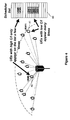
- a sector 30 of a cell contains a plurality of cellular phones or user equipments (UEs) 31 in communication with an antenna 32 at a base station.
- the base station antenna 32 communicates in a given timeslot with selected ones of the UEs 31 using three individually steered beams 321, 322, 323.
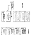
- the base station receives signals from the cellular phones 31 from which angles of arrival are determined, step 201 Figure 20.
- the angles of arrival are stored, step 202, at the base station and identifiers of the UEs 31 sorted, step 203, into angle of arrival order across the sector to form an ordered list.
- the ordered list is sub-divided, step 204, into three ordered sub-lists corresponding with the three beams 321, 322, 323, that is, with the first third of the UEs in order in the first sub-list, the second third of the UEs in order in the second sub-list and the remaining UEs in order in the third sub-list. Then every n th UE, e.g. each first member 311, 312, 313 from each of the ordered lists 331, 332, 333 is selected to form an SDMA group to which the three beams 321, 322, 323 transmit simultaneously, step 205.
- step 214 dependent on the C/I ratio, to the list before sorting, step 203. In this manner, more equal data throughput can be provided more fairly to all UEs with which the antenna communicates in the sector, in that the lower the C/I ratio the more times the UE appears in the list
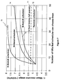
- N-from-N scheduling results in higher capacity than random scheduling, with increasing benefits up to 30 UEs that the scheduler can chose from and then a substantially constant improvement over random scheduling above 30 UEs.
- Ordered scheduling results in an improvement over N-from-N scheduling for all numbers of UEs shown up to 50 UEs.
- the ordered scheduling according to the invention approaches the optimum performance obtained by computing every possible combination of selections of UEs, as shown in plots 56, 66.
- the K-from-N scheduler, plots 55, 65 represents communication with only a selection of user equipments within the sector and ignoring of other user equipments, and is not practically feasible where a service has to be provided to all user equipments in the sector, and does not meet the criteria of equal data throughput to all UEs in the sector.
- Figure 7 shows similar results for a 5-beam antenna, from which it can be seen that for five beams random scheduling, plot 72, provides worse capacity than using 5 fixed beams with full queues, plot 71.
- the ordered scheduler according to the invention, plot 74 can be seen to provide improved capacity for all plotted values compared with an N-from-N scheduler, plot 73, i.e. choosing the best groups first and then the second best and so on.
- the K-from-N scheduler plot 75 representing communication with only a selection of user equipments within the sector and ignoring of other user equipments, is not practically feasible where a service has to be provided to all user equipments in the sector, and does not meet the criteria of equal data throughput to all user equipments in the sector.
- Figure 8 compares the mean resource usage using three to six fixed beams, plots 81-84 respectively, and three to six Minimum Mean Squared Error (MMSE) beams, plots 85 to 88 respectively, from which it can be seen that with more than 30 user equipments, the best mean resource usage is obtained with five MMSE beams, plot 87.
- MMSE Minimum Mean Squared Error
- the embodiment described above is suitable where there is little scattering between the UEs and the base station, so that a sufficiently precise Angle of Arrival may be obtained to place the UEs in order of their angles of arrival. In general, this will not be the case.
- a sector served by an antenna is divided into ranges of angle of arrival of say 1° and signatures of plane waves receivable from each range determined, step 221.
- step 221 For each of a plurality N of UEs served by a particular array, complex correlations of the spatial signature seen at the array with the plane wave excitations are calculated, step 222.
- step 222 For each UE, the correlation with one of the plane waves will be greatest and that UE is assigned, step 223, to a "bin", or range of angles of arrival, associated with the AoA of the corresponding plane wave.
- This procedure is repeated until all UEs have been assigned to a respective bin. Thereby, the UEs are ordered across the sector according to their bins. If a particular bin is empty, the ordering is thereby unaffected. If a bin has multiple UEs, the UEs in the bin are assigned an arbitrary order, such as an order in which the UEs were put into the bin.
- the SDMA groups are found as in the case with no angle spread described above.
- UEs are clustered into orthogonal sets generated by Grassmannian packing solutions and a density of packing gives some indication of the spread of the sets and the maximum cross correlation between them.
- the UEs random spatial signatures are vector-quantized to the nearest Grassmannian beams that have been pre-sorted into orthogonal groups, and assigned to the Grassmannian beam with which the spatial signature correlates, in a manner to be described hereinbelow.
- step 231 a number N of SDMA beams for the array.
- step 232 M sets of N orthogonal beams and their MxN associated Grassmannian vectors.
- step 233 For each UE, find, step 233, the Grassmannian vector with which the UE's spatial signature has maximum correlation.
- step 235 For each set of N orthogonal Grassmannian vectors, produce, step 235, a list of UEs divided into sub-lists
- step 2366 transmit, step 236, simultaneously to no more than one UE from each sub-list within the list for one of the M sets.
- M sets of orthogonal beams are needed so that the groups of UEs associated with each Grassmannian vector are disjoint across each orthogonal set, so that UEs with highly correlated spatial signatures cannot be scheduled simultaneously.
- the above method for random wavefronts does not necessarily give equal throughput to each user, either due to varying C/I and hence AMC rate, or due to unequal numbers of UEs in each sub list, or both.
- variable AMC rate can be dealt with as described earlier, by giving UEs with lower C/I ratios multiple entries in the sub-lists.
- the number of entries in each sub-list may be unequal. In some cases the number of entries can be equalised by varying the boundaries between adjacent Grassman vectors. If this is not possible, a two stage approach is available as follows:
- the number of entries served in each time slot can be arranged to be nearly equal (for example 4 sub-lists of length 2,3,4,4 can be served in groups of size 4,3,3,3). Between the M sets, variations of number of timeslots per set can be used as for standard equal throughput scheduling.
- MIMO Multiple Input Multiple Output
- Grassmannian packing theory which is known as a vector quantizer to minimize the size of a binary description of a beamformer for downlink transmit diversity.
- Grassmannian packing generates a set of m lines passing through the origin which have a maximised closest separation and each line may be equated to a generalized beam in n space for an n element transmit antenna.
- Grassmannian packing maximises the minimum angular separation of the m lines and the resulting set of vectors is maximally uniformly spaced and optimal for use as vector quantizers.
- each line direction is identified with a generalized beamformer and the closeness of the lines can be related to mutual interference between the beams.
- This has applications in beamforming design and optimization of space time block codes and unitary modulation and is the generalization of the direction resolution concepts associated with plane waves described hereinbefore applied to random channel conditions where there are no plane waves.
- the array manifold forms a basis for the vector space, since by sampling S( ⁇ ) n times with appropriate spacings the vectors can be organized into a discrete Fourier transform (DFT) matrix, which is known to be unitary and is a basis for the n-vector space.
- DFT discrete Fourier transform
- a plane wave model excludes much of the vector space, for example elements with zero amplitude are not present in (1.1) and can only be generated by adding together two plane wave signatures which cancel at one element. So there is some reason for supposing that the array manifold (1.1) does not scan over the surface of the hyperplane in a uniformly distributed manner as ⁇ is varied and is not necessarily a suitable option for scanning random channels.
- Grassmannian packing theory provides a pre-computed sampled vector space in the form of m lines which pass through the origin and which have a minimum spacing between them according to some distance metric. These lines can be assumed to be as uniformly separated in the space as possible and, for random channels, can be taken as the set of optimal beam directions which sample the field with m generalized beams.
- the m lines 91 are equally spaced around 360°, i.e. equally spaced lines pass through the origin 90 in two dimensions.
- Figure 10 shows a three-dimensional figure 100 whose vertices 101 define line directions through the centre of the figure for a best packing of 16 lines in 3-space, as known from J.H. Conway, R.H. Hardin and N.J.A. Sloane: "Packing Lines, Planes, etc., Packings in Grassmannian Spaces ", Experimental Mathematics, Vol. 5 (1996), 139-159. Interestingly the shape is asymmetric.
- the 16 vertices 101 in the three-dimensional figure 100 shown in Figure 10 are antipodal, so under some definitions there are only eight different directions. In particular, in array theory, the phases of the sources are not usually significant.
- an orthogonal set of conventional sinx/x beams allows ideal SDMA on the downlink.
- the locations of the UEs can also be arbitrary and adding zero forcing to the conventional beams generates an orthogonal set with zeros in the right places, i.e. pointing to the other UEs.
- SDMA can be achieved either by selecting orthogonal beam-forming vectors or by zero forcing but there is no guidance in the prior art how to select a set of such beams and how to relate UEs with random signatures to an orthogonal set of beams in arbitrary n-space.
- the solution is to form a set of m tiles, with similar areas, on the surface of the n sphere 110, illustrated in Figure 11.
- the Grassmannian packing vectors are an efficient way to define centres B 1 , B 2 , B 3 of these tiles and edges 112 of the tiles 111 are found in principle by generating Voronoi lines that are equidistant from two such centres B 1 , B 2 , B 3 , as shown in Figure 11.
- UE signatures 113 are classified by the tiles 111 into which they fall and for which the ⁇ defined by (2.1), between the signature and the beam, is smallest.
- Figure 11 shows a set of packing lines 114 on a 3-sphere, represented by dots B 1 , B 2 , B 3 .
- the Voronoi lines 112 divide the surface into tiles 111 and a UE is ordered according to a tile 111 into which a signature 113 of the UE falls.
- tile centres B 1 , B 2 , B 3 are separated into m orthogonal sets then m near-orthogonal tiles are used in a timeslot to perform downlink SDMA. Either the Grassmannian vectors or the actual UE signatures are used as beamformers. In either case, approximately m/n sets of orthogonal tiles are required to exhaust the whole space and using these in a sequence all UEs can be addressed in SDMA mode.
- N any integer
- N any integer
- an arbitrary 2D subspace 121 from the 2 N -dimensions is chosen and 8 directions 122 are set up in the subspace, separated by 45°.
- the plane xz is orthogonal to y. If the diagram were in 4-D there would be a similar plane orthogonal to the plane xy, the zu plane say, and 4 points and their reversals could be laid out in this plane also, leading to a total system of 8 points and their reversals.
- This provides a regular rectangular tiling with 32 points on the 4D sphere each vector W i defining the centre of a tile. Each point has four nearest neighbours at 45° separation, four neighbours at 60° and the rest of the points are orthogonal at 90°.
- a whole population of UEs are segregated into 16 sets according to their biggest dot products with the 16 columns of W, i.e. they are sorted according to which Voronoi tile their signature falls in. It is necessary to select 4 UEs out of the groups such that whatever their exact locations they are reasonably orthogonal and can be addressed in parallel using SDMA without too much mutual interference.
- the four UE signatures closest to the natural coordinate vectors are taken, to form a matrix S 1 below using columns W 1 , W 4 , W 13 , and W 16 .
- the next unused vector W 2 is taken, and the matrix S 2 completed by finding a 4 ⁇ 4 identity submatrix in W T . W, with first vector W 2 .
- This is unique and only mathematically consistent with rows and columns ⁇ 2, 7, 11, and 14 ⁇ , which are shaded in the table above to illustrate the procedure.
- the next unused vector is W 3 and with elements from columns ⁇ 3, 6, 10, and 15 ⁇ of W another identity submatrix is generated in W T W .
- This procedure has generated 4 sets of orthogonal vectors.
- the sets are not mutually orthogonal but so long as four vectors are selected from only one set four orthogonal vectors are provided.
- the 16 vectors span the vector space in a uniform manner.
- the simplicity of this selection probably is related to selecting an antenna with 2 2 elements and there is no guarantee that a similarly simple operation could be carried out for odd-numbered element antennas where the Grassmannian packing is less regular.
- Table 2 shows the cross coupling matrix when the columns of W are permuted into the order used in Equation (3.5). The coupling is now diagonal on the leading submatrix blocks.
- the vectors W 2 , W 3 , W 5 and W 9 are nearest neighbours to W 1 , having a dot product of 1/ ⁇ 2. Effectively these neighbours shift the first unit vector by 45° toward one of the other three unit vectors.
- W 2 is a common nearest neighbour of W 1 and W 4 so non-orthogonality is generated by presenting vectors in W 1 and W 4 directions which are both contaminated by addition of a small level of W 2 .
- the contamination cannot be too great or the vectors would shift into W 2 's Voronoi cell.
- W 1 + ⁇ 1 W 1 + W 2
- ( 1 + 1 2 1 2 )
- ( 1 + 1 2 1 2 ) 2 ( 1 + 1 2 )
- W 4 + ⁇ 4 W 4 + W 2
- ( 1 2 1 + 1 2 )
- ( 1 2 1 + 1 2 ) 2 ( 1 + 1 2 )
- W 4 + ⁇ 4 W 4 + W 2
- ( 1 2 1 + 1 2 )
- ( 1 2 1 + 1 2 ) 2 ( 1 + 1 2 )
- the 4 ⁇ 4 DFT matrix is used for Q.
- S ′ 1 ( 1 1 1 1 1 j ⁇ 1 ⁇ j 1 ⁇ 1 1 ⁇ 1 1 ⁇ j ⁇ 1 j )
- S ′ 2 ( 2 0 0 2 1 2 ( 1 + j ) 0 1 ⁇ j 1 2 ( ⁇ 1 ⁇ j ) 0 2 0 0 1 2 ( 1 ⁇ j ) 0 1 + j 1 2 ( ⁇ 1 + j ) )
- S ′ 3 ( 0 2 0 0 1 2 ( 1 ⁇ j ) 0 1 + j 1 2 ( ⁇ 1 + j ) 0 0 0 2 1 2 ( 1 + j ) 0 1 ⁇ j 1 2 ( ⁇ 1 ⁇ j ) )
- S ′ 4 ( 2 2 0 0 0 0 2 2 j 2 ⁇ 2 0 0 0 2 ⁇ 2 ⁇ 2 0 0 0 2 ⁇ 2 ⁇ 2 ⁇ 2 ⁇ 2 ⁇ 2
- the first set is just the conventional DFT matrix, an orthogonal set of plane waves, and we may have expected to get interpolating beams for one of the other sets, but this is not the case and it is not yet clear what the rest of the beams represent.
- Figure 15 By selecting UEs in turn from one of two sets of fragmented zones, as shown in Figure 15, it can be guaranteed that no two UEs will be closer than 1 ⁇ 2 beamwidth and the cross coupling will always be less than 2/ ⁇ .
- Figures 16 and 17 show bit rate performance obtained using tracking conventional beams, zero forcing, and MIMO. Apart from a slight excess of low rate transfers, the system operates quite close to the Shannon limit.
- UE signatures are generated randomly using four real Gaussian random numbers, which are known to be spherically symmetric in any number of dimensions, unlike uniform random numbers, which form cubical probability distribution functions.
- the generator is run until a vector has occupied each tile and each signature is then normalised to unit length.
- Figure 18 shows the cumulative distribution function of UE bit rates for a 10 dB transmitter power using a conventional tracking beam, zero forcing and MIMO options.
- Figure 19 shows the result of increasing the transmitter power to 20 dB. Again the results are similar to the plane wave results for a comparable situation.
- the downlink SDMA throughput for a random channel matrix using beamformers derived from a form of Grassmannian line packing has been tested.
- 16 equally spaced beams in 4-space can be found with a maximum cross coupling of 1/ ⁇ 2. This is more beams than the usual plane wave conventional beams would need, where there would be only eight beams at half beamwidth spacing with a maximum coupling of sin1 ⁇ 2 ⁇ / 1 ⁇ 2 ⁇ .
- the throughput is comparable to tests on downlink plane wave beamforming in an ideal channel so is quite close to the Shannon bound for four ideal orthogonal downlinks. This indicates that there is no impediment to multiple access (SDMA) in random channels compared with ideal channels.
- SDMA multiple access
- Alternative embodiments of the invention can be implemented as a computer program product for use with a computer system, the computer program product being, for example, a series of computer instructions stored on a tangible data recording medium, such as a diskette, CD-ROM, ROM, or fixed disk, or embodied in a computer data signal, the signal being transmitted over a tangible medium or a wireless medium, for example microwave or infrared.
- the series of computer instructions can constitute all or part of the functionality described above, and can also be stored in any memory device, volatile or non-volatile, such as semiconductor, magnetic, optical or other memory device.
Landscapes
- Engineering & Computer Science (AREA)
- Computer Networks & Wireless Communication (AREA)
- Signal Processing (AREA)
- Mobile Radio Communication Systems (AREA)
- Information Retrieval, Db Structures And Fs Structures Therefor (AREA)
- Telephonic Communication Services (AREA)
- Cash Registers Or Receiving Machines (AREA)
- Radio Transmission System (AREA)
Applications Claiming Priority (1)
| Application Number | Priority Date | Filing Date | Title |
|---|---|---|---|
| US10/928,454 US7620019B1 (en) | 2004-08-27 | 2004-08-27 | Space division multiple access scheduling |
Publications (2)
| Publication Number | Publication Date |
|---|---|
| EP1631100A1 true EP1631100A1 (de) | 2006-03-01 |
| EP1631100B1 EP1631100B1 (de) | 2010-03-31 |
Family
ID=35456937
Family Applications (1)
| Application Number | Title | Priority Date | Filing Date |
|---|---|---|---|
| EP05017861A Ceased EP1631100B1 (de) | 2004-08-27 | 2005-08-17 | SDMA-Einteilung durch Sortierung von Benutzer-Endgeräten in der Reihenfolge ihres Einfallswinkels und Unterteilung der geordneten Liste in sortierte Unterlisten |
Country Status (4)
| Country | Link |
|---|---|
| US (1) | US7620019B1 (de) |
| EP (1) | EP1631100B1 (de) |
| AT (1) | ATE463137T1 (de) |
| DE (1) | DE602005020224D1 (de) |
Cited By (6)
| Publication number | Priority date | Publication date | Assignee | Title |
|---|---|---|---|---|
| EP1876847A1 (de) * | 2006-07-07 | 2008-01-09 | Alcatel Lucent | Ein Verfahren zur Ablaufsteuerung von Teilnehmerendgeräten in einem SDMA Kommunikationsnetz, sowie eine Basisstation und ein Netz dafür |
| EP2271009A4 (de) * | 2009-05-08 | 2011-04-27 | Zte Corp | Verfahren zur bildung von einem mehrnutzerstrahl beruhend auf frequenzteilungs-duplex sowie zugehörige vorrichtung |
| WO2017106868A1 (en) * | 2015-12-17 | 2017-06-22 | Legba, Inc. | High-bandwidth beamforming lte base station |
| WO2019228652A1 (en) * | 2018-06-01 | 2019-12-05 | Telefonaktiebolaget Lm Ericsson (Publ) | Approaches for beam selection |
| WO2020207170A1 (zh) * | 2019-04-11 | 2020-10-15 | 华为技术有限公司 | 一种确定用户终端ue位置的方法以及处理装置 |
| US11122571B2 (en) | 2018-11-30 | 2021-09-14 | Telefonaktiebolaget Lm Ericsson (Publ) | Approaches for beam selection |
Families Citing this family (19)
| Publication number | Priority date | Publication date | Assignee | Title |
|---|---|---|---|---|
| JP4832087B2 (ja) * | 2005-01-26 | 2011-12-07 | パナソニック株式会社 | 無線基地局装置及び端末装置 |
| US8144666B2 (en) * | 2005-05-13 | 2012-03-27 | Rockstar Bidco Lp | Downlink beamforming for broadband wireless networks |
| US8340006B2 (en) * | 2006-04-12 | 2012-12-25 | Panasonic Corporation | Transmission of multicast/broadcast services in a wireless communication network |
| US8036669B2 (en) * | 2006-04-20 | 2011-10-11 | Qualcomm Incorporated | Orthogonal resource reuse with SDMA beams |
| KR20070113967A (ko) * | 2006-05-26 | 2007-11-29 | 엘지전자 주식회사 | 위상천이 기반의 프리코딩 방법 및 이를 지원하는 송수신기 |
| TWI343200B (en) * | 2006-05-26 | 2011-06-01 | Lg Electronics Inc | Method and apparatus for signal generation using phase-shift based pre-coding |
| JP4899637B2 (ja) * | 2006-05-29 | 2012-03-21 | 株式会社日立製作所 | 無線通信システムおよび無線通信方法 |
| KR20080026019A (ko) * | 2006-09-19 | 2008-03-24 | 엘지전자 주식회사 | 위상천이 기반의 프리코딩 방법 및 이를 지원하는 송수신기 |
| KR20080026010A (ko) * | 2006-09-19 | 2008-03-24 | 엘지전자 주식회사 | 위상천이 기반의 프리코딩을 이용한 데이터 전송 방법 및이를 구현하는 송수신 장치 |
| KR20080076683A (ko) * | 2007-02-14 | 2008-08-20 | 엘지전자 주식회사 | 위상천이 기반의 프리코딩 방법 및 이를 지원하는 송수신기 |
| KR20090030200A (ko) * | 2007-09-19 | 2009-03-24 | 엘지전자 주식회사 | 위상천이 기반의 프리코딩을 이용한 데이터 송수신 방법 및이를 지원하는 송수신기 |
| KR101381465B1 (ko) * | 2008-02-20 | 2014-04-04 | 삼성전자주식회사 | 채널 상태 정보를 피드백하는 공간 다중 접속 방식의 통신시스템 및 이를 지원하는 방법 |
| US9173191B2 (en) | 2009-12-20 | 2015-10-27 | Intel Corporation | Device, system and method of simultaneously communicating with a group of wireless communication devices |
| US8374154B2 (en) * | 2009-12-23 | 2013-02-12 | Intel Corporation | Device, system and method of simultaneously communicating with a group of wireless communication devices |
| US9609648B2 (en) | 2014-06-16 | 2017-03-28 | Qualcomm Incorporated | Beamform scheduling based on the directionality of UEs |
| EP3361648B1 (de) * | 2017-02-08 | 2020-09-02 | Fraunhofer-Gesellschaft zur Förderung der angewandten Forschung e.V. | Zellulares kommunikationsnetz mit einem identifikator für das benutzerendgerät |
| US11347816B2 (en) | 2017-12-01 | 2022-05-31 | At&T Intellectual Property I, L.P. | Adaptive clustering of media content from multiple different domains |
| EP4092920A3 (de) * | 2021-05-20 | 2023-04-05 | Nokia Technologies Oy | Benutzervorrichtungsplanung |
| JP2025517409A (ja) * | 2022-05-17 | 2025-06-05 | コヒア テクノロジーズ,インコーポレイテッド | 空間多様性の測定、追跡、および管理 |
Citations (4)
| Publication number | Priority date | Publication date | Assignee | Title |
|---|---|---|---|---|
| WO2001043309A2 (en) * | 1999-12-01 | 2001-06-14 | Metawave Communications Corporation | Adaptive antenna array wireless data access point |
| US6330460B1 (en) * | 2000-08-21 | 2001-12-11 | Metawave Communications Corporation | Simultaneous forward link beam forming and learning method for mobile high rate data traffic |
| US6347234B1 (en) * | 1997-09-15 | 2002-02-12 | Adaptive Telecom, Inc. | Practical space-time radio method for CDMA communication capacity enhancement |
| US20020058514A1 (en) * | 2000-11-10 | 2002-05-16 | Nortel Networks Limited | Multibeam wireless communications method and system including an interference avoidance scheme in which the area of each transmitted beam is divided into a plurality of sub-areas |
Family Cites Families (6)
| Publication number | Priority date | Publication date | Assignee | Title |
|---|---|---|---|---|
| US5634199A (en) * | 1993-04-14 | 1997-05-27 | Stanford University | Method of subspace beamforming using adaptive transmitting antennas with feedback |
| JP3872953B2 (ja) * | 1999-12-27 | 2007-01-24 | 株式会社東芝 | アダプティブアンテナを用いた無線通信装置 |
| JP3910349B2 (ja) * | 2000-09-19 | 2007-04-25 | 株式会社日立コミュニケーションテクノロジー | 指向性アンテナの制御方法および装置 |
| US20030204378A1 (en) * | 2001-06-26 | 2003-10-30 | Cai Khiem V. | System and method for forming a beam and creating nulls with an adaptive array antenna using orthogonal eigen-weighting |
| JP3693940B2 (ja) * | 2001-07-26 | 2005-09-14 | シャープ株式会社 | スイッチング電源装置 |
| US20050286663A1 (en) * | 2004-06-23 | 2005-12-29 | Intel Corporation | Compact feedback for closed loop MIMO systems |
-
2004
- 2004-08-27 US US10/928,454 patent/US7620019B1/en not_active Expired - Fee Related
-
2005
- 2005-08-17 DE DE602005020224T patent/DE602005020224D1/de not_active Expired - Lifetime
- 2005-08-17 AT AT05017861T patent/ATE463137T1/de not_active IP Right Cessation
- 2005-08-17 EP EP05017861A patent/EP1631100B1/de not_active Ceased
Patent Citations (4)
| Publication number | Priority date | Publication date | Assignee | Title |
|---|---|---|---|---|
| US6347234B1 (en) * | 1997-09-15 | 2002-02-12 | Adaptive Telecom, Inc. | Practical space-time radio method for CDMA communication capacity enhancement |
| WO2001043309A2 (en) * | 1999-12-01 | 2001-06-14 | Metawave Communications Corporation | Adaptive antenna array wireless data access point |
| US6330460B1 (en) * | 2000-08-21 | 2001-12-11 | Metawave Communications Corporation | Simultaneous forward link beam forming and learning method for mobile high rate data traffic |
| US20020058514A1 (en) * | 2000-11-10 | 2002-05-16 | Nortel Networks Limited | Multibeam wireless communications method and system including an interference avoidance scheme in which the area of each transmitted beam is divided into a plurality of sub-areas |
Cited By (10)
| Publication number | Priority date | Publication date | Assignee | Title |
|---|---|---|---|---|
| EP1876847A1 (de) * | 2006-07-07 | 2008-01-09 | Alcatel Lucent | Ein Verfahren zur Ablaufsteuerung von Teilnehmerendgeräten in einem SDMA Kommunikationsnetz, sowie eine Basisstation und ein Netz dafür |
| EP2271009A4 (de) * | 2009-05-08 | 2011-04-27 | Zte Corp | Verfahren zur bildung von einem mehrnutzerstrahl beruhend auf frequenzteilungs-duplex sowie zugehörige vorrichtung |
| US8189498B2 (en) | 2009-05-08 | 2012-05-29 | Zte Corporation | Method and device for multi-user beamforming based on a frequency division duplex system |
| US8837407B2 (en) | 2009-05-08 | 2014-09-16 | Zte Corporation | Method and device for multi-user beamforming based on a frequency division duplex system |
| WO2017106868A1 (en) * | 2015-12-17 | 2017-06-22 | Legba, Inc. | High-bandwidth beamforming lte base station |
| WO2019228652A1 (en) * | 2018-06-01 | 2019-12-05 | Telefonaktiebolaget Lm Ericsson (Publ) | Approaches for beam selection |
| US11483053B2 (en) | 2018-06-01 | 2022-10-25 | Telefonaktiebolaget Lm Ericsson (Publ) | Approaches for beam selection |
| US11122571B2 (en) | 2018-11-30 | 2021-09-14 | Telefonaktiebolaget Lm Ericsson (Publ) | Approaches for beam selection |
| US11838904B2 (en) | 2018-11-30 | 2023-12-05 | Telefonaktiebolaget Lm Ericsson (Publ) | Approaches for beam selection |
| WO2020207170A1 (zh) * | 2019-04-11 | 2020-10-15 | 华为技术有限公司 | 一种确定用户终端ue位置的方法以及处理装置 |
Also Published As
| Publication number | Publication date |
|---|---|
| DE602005020224D1 (de) | 2010-05-12 |
| EP1631100B1 (de) | 2010-03-31 |
| US7620019B1 (en) | 2009-11-17 |
| ATE463137T1 (de) | 2010-04-15 |
Similar Documents
| Publication | Publication Date | Title |
|---|---|---|
| EP1631100B1 (de) | SDMA-Einteilung durch Sortierung von Benutzer-Endgeräten in der Reihenfolge ihres Einfallswinkels und Unterteilung der geordneten Liste in sortierte Unterlisten | |
| EP3216135B1 (de) | Effiziente strahlabtastung auf drahtlose hochfrequenznetzwerke | |
| KR102502746B1 (ko) | 무선 통신 시스템에서 안테나 어레이를 이용하여 신호를 데이터를 하기 위한 장치 및 방법 | |
| Kutty et al. | Beamforming for millimeter wave communications: An inclusive survey | |
| US8526886B2 (en) | Wireless communication device and method for controlling beam to be transmitted | |
| Adhikary et al. | Joint spatial division and multiplexing: Opportunistic beamforming and user grouping | |
| Olenko et al. | Analytically derived uplink/downlink TOA and 2-D-DOA distributions with scatterers in a 3-D hemispheroid surrounding the mobile | |
| EP3683975A1 (de) | Verfahren zur aktivierung der analogen vorcodierung und der analogen kombinierung | |
| Li et al. | Directional training and fast sector-based processing schemes for mmwave channels | |
| Li et al. | Efficient antenna allocation algorithms in millimetre wave wireless communications | |
| Tall et al. | Multilevel beamforming for high data rate communication in 5G networks | |
| Bernabè et al. | Massive MIMO for aerial highways: Enhancing cell selection via SSB beams optimization | |
| CN106452713B (zh) | 一种导频污染减轻方法及装置 | |
| Anjum et al. | Dedicated versus shared element-allotment in IRS-aided wireless systems: When to use what? | |
| Tashiro et al. | Cylindrical massive MIMO system with low-complexity angle-based user selection for high-altitude platform stations | |
| Bao et al. | Resource allocation for joint communication and localization systems with MU-MIMO | |
| Bursalioglu et al. | A novel alternative to cloud RAN for throughput densification: Coded pilots and fast user-packet scheduling at remote radio heads | |
| CN105356922B (zh) | 3d mimo信道下基于非均匀分割的垂直维码本设计方法 | |
| CN116981037B (zh) | 无线携能通信方法与系统 | |
| Chalise et al. | Robust downlink beamforming based upon outage probability criterion [cellular radio] | |
| Masmoudi et al. | User grouping and hybrid RF/baseband precoding for multi-user massive MIMO systems | |
| Paisana et al. | Cognitive beamforming in radar bands | |
| Chalise et al. | Robust uplink beamforming based upon minimum outage probability criterion | |
| Amiri | Peak Downlink Rate Maximization and Joint Beamforming Optimization for RIS-Aided THz OFDMA UM-MIMO Communications | |
| Hamada et al. | Characterization of sub-THz-band MIMO spatial multiplexing in indoor environments |
Legal Events
| Date | Code | Title | Description |
|---|---|---|---|
| PUAI | Public reference made under article 153(3) epc to a published international application that has entered the european phase |
Free format text: ORIGINAL CODE: 0009012 |
|
| AK | Designated contracting states |
Kind code of ref document: A1 Designated state(s): AT BE BG CH CY CZ DE DK EE ES FI FR GB GR HU IE IS IT LI LT LU LV MC NL PL PT RO SE SI SK TR |
|
| AX | Request for extension of the european patent |
Extension state: AL BA HR MK YU |
|
| 17P | Request for examination filed |
Effective date: 20060713 |
|
| 17Q | First examination report despatched |
Effective date: 20060814 |
|
| AKX | Designation fees paid |
Designated state(s): AT BE BG CH CY CZ DE DK EE ES FI FR GB GR HU IE IS IT LI LT LU LV MC NL PL PT RO SE SI SK TR |
|
| GRAP | Despatch of communication of intention to grant a patent |
Free format text: ORIGINAL CODE: EPIDOSNIGR1 |
|
| RIC1 | Information provided on ipc code assigned before grant |
Ipc: H04W 16/28 20090101AFI20090909BHEP |
|
| GRAS | Grant fee paid |
Free format text: ORIGINAL CODE: EPIDOSNIGR3 |
|
| GRAL | Information related to payment of fee for publishing/printing deleted |
Free format text: ORIGINAL CODE: EPIDOSDIGR3 |
|
| GRAS | Grant fee paid |
Free format text: ORIGINAL CODE: EPIDOSNIGR3 |
|
| GRAA | (expected) grant |
Free format text: ORIGINAL CODE: 0009210 |
|
| AK | Designated contracting states |
Kind code of ref document: B1 Designated state(s): AT BE BG CH CY CZ DE DK EE ES FI FR GB GR HU IE IS IT LI LT LU LV MC NL PL PT RO SE SI SK TR |
|
| REG | Reference to a national code |
Ref country code: CH Ref legal event code: EP Ref country code: GB Ref legal event code: FG4D |
|
| REG | Reference to a national code |
Ref country code: IE Ref legal event code: FG4D |
|
| REF | Corresponds to: |
Ref document number: 602005020224 Country of ref document: DE Date of ref document: 20100512 Kind code of ref document: P |
|
| REG | Reference to a national code |
Ref country code: NL Ref legal event code: VDEP Effective date: 20100331 |
|
| PG25 | Lapsed in a contracting state [announced via postgrant information from national office to epo] |
Ref country code: LT Free format text: LAPSE BECAUSE OF FAILURE TO SUBMIT A TRANSLATION OF THE DESCRIPTION OR TO PAY THE FEE WITHIN THE PRESCRIBED TIME-LIMIT Effective date: 20100331 |
|
| LTIE | Lt: invalidation of european patent or patent extension |
Effective date: 20100331 |
|
| PG25 | Lapsed in a contracting state [announced via postgrant information from national office to epo] |
Ref country code: LV Free format text: LAPSE BECAUSE OF FAILURE TO SUBMIT A TRANSLATION OF THE DESCRIPTION OR TO PAY THE FEE WITHIN THE PRESCRIBED TIME-LIMIT Effective date: 20100331 Ref country code: FI Free format text: LAPSE BECAUSE OF FAILURE TO SUBMIT A TRANSLATION OF THE DESCRIPTION OR TO PAY THE FEE WITHIN THE PRESCRIBED TIME-LIMIT Effective date: 20100331 Ref country code: SI Free format text: LAPSE BECAUSE OF FAILURE TO SUBMIT A TRANSLATION OF THE DESCRIPTION OR TO PAY THE FEE WITHIN THE PRESCRIBED TIME-LIMIT Effective date: 20100331 Ref country code: AT Free format text: LAPSE BECAUSE OF FAILURE TO SUBMIT A TRANSLATION OF THE DESCRIPTION OR TO PAY THE FEE WITHIN THE PRESCRIBED TIME-LIMIT Effective date: 20100331 Ref country code: PL Free format text: LAPSE BECAUSE OF FAILURE TO SUBMIT A TRANSLATION OF THE DESCRIPTION OR TO PAY THE FEE WITHIN THE PRESCRIBED TIME-LIMIT Effective date: 20100331 |
|
| PG25 | Lapsed in a contracting state [announced via postgrant information from national office to epo] |
Ref country code: NL Free format text: LAPSE BECAUSE OF FAILURE TO SUBMIT A TRANSLATION OF THE DESCRIPTION OR TO PAY THE FEE WITHIN THE PRESCRIBED TIME-LIMIT Effective date: 20100331 Ref country code: BE Free format text: LAPSE BECAUSE OF FAILURE TO SUBMIT A TRANSLATION OF THE DESCRIPTION OR TO PAY THE FEE WITHIN THE PRESCRIBED TIME-LIMIT Effective date: 20100331 Ref country code: SE Free format text: LAPSE BECAUSE OF FAILURE TO SUBMIT A TRANSLATION OF THE DESCRIPTION OR TO PAY THE FEE WITHIN THE PRESCRIBED TIME-LIMIT Effective date: 20100331 Ref country code: RO Free format text: LAPSE BECAUSE OF FAILURE TO SUBMIT A TRANSLATION OF THE DESCRIPTION OR TO PAY THE FEE WITHIN THE PRESCRIBED TIME-LIMIT Effective date: 20100331 Ref country code: ES Free format text: LAPSE BECAUSE OF FAILURE TO SUBMIT A TRANSLATION OF THE DESCRIPTION OR TO PAY THE FEE WITHIN THE PRESCRIBED TIME-LIMIT Effective date: 20100712 Ref country code: EE Free format text: LAPSE BECAUSE OF FAILURE TO SUBMIT A TRANSLATION OF THE DESCRIPTION OR TO PAY THE FEE WITHIN THE PRESCRIBED TIME-LIMIT Effective date: 20100331 Ref country code: CY Free format text: LAPSE BECAUSE OF FAILURE TO SUBMIT A TRANSLATION OF THE DESCRIPTION OR TO PAY THE FEE WITHIN THE PRESCRIBED TIME-LIMIT Effective date: 20100331 |
|
| PG25 | Lapsed in a contracting state [announced via postgrant information from national office to epo] |
Ref country code: SK Free format text: LAPSE BECAUSE OF FAILURE TO SUBMIT A TRANSLATION OF THE DESCRIPTION OR TO PAY THE FEE WITHIN THE PRESCRIBED TIME-LIMIT Effective date: 20100331 Ref country code: CZ Free format text: LAPSE BECAUSE OF FAILURE TO SUBMIT A TRANSLATION OF THE DESCRIPTION OR TO PAY THE FEE WITHIN THE PRESCRIBED TIME-LIMIT Effective date: 20100331 Ref country code: IS Free format text: LAPSE BECAUSE OF FAILURE TO SUBMIT A TRANSLATION OF THE DESCRIPTION OR TO PAY THE FEE WITHIN THE PRESCRIBED TIME-LIMIT Effective date: 20100731 |
|
| PG25 | Lapsed in a contracting state [announced via postgrant information from national office to epo] |
Ref country code: PT Free format text: LAPSE BECAUSE OF FAILURE TO SUBMIT A TRANSLATION OF THE DESCRIPTION OR TO PAY THE FEE WITHIN THE PRESCRIBED TIME-LIMIT Effective date: 20100802 Ref country code: DK Free format text: LAPSE BECAUSE OF FAILURE TO SUBMIT A TRANSLATION OF THE DESCRIPTION OR TO PAY THE FEE WITHIN THE PRESCRIBED TIME-LIMIT Effective date: 20100331 |
|
| PLBE | No opposition filed within time limit |
Free format text: ORIGINAL CODE: 0009261 |
|
| STAA | Information on the status of an ep patent application or granted ep patent |
Free format text: STATUS: NO OPPOSITION FILED WITHIN TIME LIMIT |
|
| 26N | No opposition filed |
Effective date: 20110104 |
|
| PG25 | Lapsed in a contracting state [announced via postgrant information from national office to epo] |
Ref country code: MC Free format text: LAPSE BECAUSE OF NON-PAYMENT OF DUE FEES Effective date: 20100831 Ref country code: IT Free format text: LAPSE BECAUSE OF FAILURE TO SUBMIT A TRANSLATION OF THE DESCRIPTION OR TO PAY THE FEE WITHIN THE PRESCRIBED TIME-LIMIT Effective date: 20100331 |
|
| REG | Reference to a national code |
Ref country code: CH Ref legal event code: PL |
|
| PG25 | Lapsed in a contracting state [announced via postgrant information from national office to epo] |
Ref country code: CH Free format text: LAPSE BECAUSE OF NON-PAYMENT OF DUE FEES Effective date: 20100831 Ref country code: LI Free format text: LAPSE BECAUSE OF NON-PAYMENT OF DUE FEES Effective date: 20100831 |
|
| PG25 | Lapsed in a contracting state [announced via postgrant information from national office to epo] |
Ref country code: IE Free format text: LAPSE BECAUSE OF NON-PAYMENT OF DUE FEES Effective date: 20100817 |
|
| PG25 | Lapsed in a contracting state [announced via postgrant information from national office to epo] |
Ref country code: HU Free format text: LAPSE BECAUSE OF FAILURE TO SUBMIT A TRANSLATION OF THE DESCRIPTION OR TO PAY THE FEE WITHIN THE PRESCRIBED TIME-LIMIT Effective date: 20101001 Ref country code: BG Free format text: LAPSE BECAUSE OF FAILURE TO SUBMIT A TRANSLATION OF THE DESCRIPTION OR TO PAY THE FEE WITHIN THE PRESCRIBED TIME-LIMIT Effective date: 20100331 Ref country code: LU Free format text: LAPSE BECAUSE OF NON-PAYMENT OF DUE FEES Effective date: 20100817 |
|
| PG25 | Lapsed in a contracting state [announced via postgrant information from national office to epo] |
Ref country code: TR Free format text: LAPSE BECAUSE OF FAILURE TO SUBMIT A TRANSLATION OF THE DESCRIPTION OR TO PAY THE FEE WITHIN THE PRESCRIBED TIME-LIMIT Effective date: 20100331 |
|
| REG | Reference to a national code |
Ref country code: DE Ref legal event code: R082 Ref document number: 602005020224 Country of ref document: DE |
|
| REG | Reference to a national code |
Ref country code: GB Ref legal event code: 732E Free format text: REGISTERED BETWEEN 20130502 AND 20130508 |
|
| REG | Reference to a national code |
Ref country code: GB Ref legal event code: 732E Free format text: REGISTERED BETWEEN 20130509 AND 20130515 |
|
| REG | Reference to a national code |
Ref country code: FR Ref legal event code: TP Owner name: APPLE INC., US Effective date: 20130515 |
|
| PG25 | Lapsed in a contracting state [announced via postgrant information from national office to epo] |
Ref country code: BG Free format text: LAPSE BECAUSE OF FAILURE TO SUBMIT A TRANSLATION OF THE DESCRIPTION OR TO PAY THE FEE WITHIN THE PRESCRIBED TIME-LIMIT Effective date: 20100630 |
|
| REG | Reference to a national code |
Ref country code: DE Ref legal event code: R082 Ref document number: 602005020224 Country of ref document: DE Representative=s name: BARDEHLE PAGENBERG PARTNERSCHAFT MBB PATENTANW, DE Effective date: 20130528 Ref country code: DE Ref legal event code: R081 Ref document number: 602005020224 Country of ref document: DE Owner name: APPLE INC., US Free format text: FORMER OWNER: NORTEL NETWORKS LTD., ST. LAURENT, CA Effective date: 20140313 Ref country code: DE Ref legal event code: R082 Ref document number: 602005020224 Country of ref document: DE Representative=s name: BARDEHLE PAGENBERG PARTNERSCHAFT MBB PATENTANW, DE Effective date: 20140313 Ref country code: DE Ref legal event code: R081 Ref document number: 602005020224 Country of ref document: DE Owner name: APPLE INC., CUPERTINO, US Free format text: FORMER OWNER: NORTEL NETWORKS LTD., ST. LAURENT, QUEBEC, CA Effective date: 20140313 |
|
| PG25 | Lapsed in a contracting state [announced via postgrant information from national office to epo] |
Ref country code: GR Free format text: LAPSE BECAUSE OF FAILURE TO SUBMIT A TRANSLATION OF THE DESCRIPTION OR TO PAY THE FEE WITHIN THE PRESCRIBED TIME-LIMIT Effective date: 20100331 |
|
| REG | Reference to a national code |
Ref country code: FR Ref legal event code: PLFP Year of fee payment: 12 |
|
| REG | Reference to a national code |
Ref country code: FR Ref legal event code: PLFP Year of fee payment: 13 |
|
| PGFP | Annual fee paid to national office [announced via postgrant information from national office to epo] |
Ref country code: ES Payment date: 20170928 Year of fee payment: 13 |
|
| REG | Reference to a national code |
Ref country code: FR Ref legal event code: PLFP Year of fee payment: 14 |
|
| PGFP | Annual fee paid to national office [announced via postgrant information from national office to epo] |
Ref country code: FR Payment date: 20180712 Year of fee payment: 14 Ref country code: DE Payment date: 20180807 Year of fee payment: 14 |
|
| GBPC | Gb: european patent ceased through non-payment of renewal fee |
Effective date: 20180817 |
|
| PG25 | Lapsed in a contracting state [announced via postgrant information from national office to epo] |
Ref country code: GB Free format text: LAPSE BECAUSE OF NON-PAYMENT OF DUE FEES Effective date: 20180817 |
|
| REG | Reference to a national code |
Ref country code: DE Ref legal event code: R119 Ref document number: 602005020224 Country of ref document: DE |
|
| PG25 | Lapsed in a contracting state [announced via postgrant information from national office to epo] |
Ref country code: DE Free format text: LAPSE BECAUSE OF NON-PAYMENT OF DUE FEES Effective date: 20200303 Ref country code: FR Free format text: LAPSE BECAUSE OF NON-PAYMENT OF DUE FEES Effective date: 20190831 |