EP1630829A1 - Dispositif de fabrication d'une gaine alvéolée autour d'un conducteur - Google Patents
Dispositif de fabrication d'une gaine alvéolée autour d'un conducteur Download PDFInfo
- Publication number
- EP1630829A1 EP1630829A1 EP05300689A EP05300689A EP1630829A1 EP 1630829 A1 EP1630829 A1 EP 1630829A1 EP 05300689 A EP05300689 A EP 05300689A EP 05300689 A EP05300689 A EP 05300689A EP 1630829 A1 EP1630829 A1 EP 1630829A1
- Authority
- EP
- European Patent Office
- Prior art keywords
- sleeve
- manufacturing
- guide
- central
- central guide
- Prior art date
- Legal status (The legal status is an assumption and is not a legal conclusion. Google has not performed a legal analysis and makes no representation as to the accuracy of the status listed.)
- Granted
Links
Images

Classifications
-
- H—ELECTRICITY
- H01—ELECTRIC ELEMENTS
- H01B—CABLES; CONDUCTORS; INSULATORS; SELECTION OF MATERIALS FOR THEIR CONDUCTIVE, INSULATING OR DIELECTRIC PROPERTIES
- H01B13/00—Apparatus or processes specially adapted for manufacturing conductors or cables
- H01B13/06—Insulating conductors or cables
- H01B13/14—Insulating conductors or cables by extrusion
- H01B13/142—Insulating conductors or cables by extrusion of cellular material
-
- H—ELECTRICITY
- H01—ELECTRIC ELEMENTS
- H01B—CABLES; CONDUCTORS; INSULATORS; SELECTION OF MATERIALS FOR THEIR CONDUCTIVE, INSULATING OR DIELECTRIC PROPERTIES
- H01B7/00—Insulated conductors or cables characterised by their form
- H01B7/02—Disposition of insulation
-
- H—ELECTRICITY
- H01—ELECTRIC ELEMENTS
- H01B—CABLES; CONDUCTORS; INSULATORS; SELECTION OF MATERIALS FOR THEIR CONDUCTIVE, INSULATING OR DIELECTRIC PROPERTIES
- H01B13/00—Apparatus or processes specially adapted for manufacturing conductors or cables
- H01B13/06—Insulating conductors or cables
- H01B13/14—Insulating conductors or cables by extrusion
- H01B13/143—Insulating conductors or cables by extrusion with a special opening of the extrusion head
-
- Y—GENERAL TAGGING OF NEW TECHNOLOGICAL DEVELOPMENTS; GENERAL TAGGING OF CROSS-SECTIONAL TECHNOLOGIES SPANNING OVER SEVERAL SECTIONS OF THE IPC; TECHNICAL SUBJECTS COVERED BY FORMER USPC CROSS-REFERENCE ART COLLECTIONS [XRACs] AND DIGESTS
- Y10—TECHNICAL SUBJECTS COVERED BY FORMER USPC
- Y10T—TECHNICAL SUBJECTS COVERED BY FORMER US CLASSIFICATION
- Y10T29/00—Metal working
- Y10T29/49—Method of mechanical manufacture
- Y10T29/49002—Electrical device making
- Y10T29/49117—Conductor or circuit manufacturing
-
- Y—GENERAL TAGGING OF NEW TECHNOLOGICAL DEVELOPMENTS; GENERAL TAGGING OF CROSS-SECTIONAL TECHNOLOGIES SPANNING OVER SEVERAL SECTIONS OF THE IPC; TECHNICAL SUBJECTS COVERED BY FORMER USPC CROSS-REFERENCE ART COLLECTIONS [XRACs] AND DIGESTS
- Y10—TECHNICAL SUBJECTS COVERED BY FORMER USPC
- Y10T—TECHNICAL SUBJECTS COVERED BY FORMER US CLASSIFICATION
- Y10T29/00—Metal working
- Y10T29/53—Means to assemble or disassemble
- Y10T29/5313—Means to assemble electrical device
- Y10T29/532—Conductor
Definitions
- the present invention relates to a method and a device for manufacturing a cellular sheath of a conductor. It relates more particularly, but without limitation, to the manufacture of intermediate dielectric sheaths of coaxial cables.
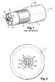
- FIG. 1 illustrates an example of a coaxial cable according to the prior art.
- the coaxial cable 10 generally comprises a central conductor 4 surrounded by an intermediate sheath 5, or insulation, made of an insulating dielectric material.
- the central conductor 4 may for example be solid or in the form of a strand, as shown in FIG. 1.
- the intermediate sheath must have specific dielectric properties in order to obtain the required attenuation characteristics for the coaxial cable, especially for relatively high frequencies. Specifically, it is generally required that the intermediate sheath has a dielectric constant less than about 1.8, and as close as possible to 1. The higher the dielectric constant is close to 1, the higher the coaxial cable can be used.
- the dielectric constants of the insulating materials conventionally used in cabling for example polyethylene or polytetrafluoroethylene (PTFE), have a value close to 2 when these insulating materials are used in a massive form.
- PTFE polytetrafluoroethylene
- the cellular sheaths are made of an insulating material comprising a plurality of air-filled bubbles or a dielectric constant gas close to 1, such that the dielectric constant of the cellular sheath is smaller than the dielectric constant of the material. insulation alone.
- the cellular sheaths have cells extending rectilinearly or helically along the coaxial cable. As shown in FIG. 1, walls 53, 51 and 54 make it possible to separate the cells 52 from each other, the central conductor 4, and the outer protective sheath 7.
- the cells may have various shapes.
- the cells can be closed, as shown in Figure 1, that is to say that each cell is completely surrounded by walls of insulating material.
- the cells can also lead directly to the driver.
- the cells are obtained by shaping the insulating material used, with the aid of an extrusion device having suitable openings and passages for this purpose.
- European Patent EP 0 803 878 describes a method and a device for manufacturing such a cellular sheath.
- the manufacturing device comprises a central guide comprising a longitudinal channel for the passage of a conductor.
- the manufacturing device also includes a coaxial die surrounding the central guide.
- An outer surface of the central guide and an inner surface of the die define a passage for an insulating material in the viscous state.
- the die comprises openings communicating with the passage. The openings are intended to receive the insulating material in the viscous state, and have a shape adapted to allow the formation of cells.
- the insulating material is thus shaped by extrusion and then applied to the conductor at a distance from the die such as the material insulation is sufficiently stretched so that the walls of the cells do not collapse under the effect of the depression at the exit of the die.
- the die comprises several openings, so as to allow the formation of a number of cells typically between 4 and 6.
- a given die is therefore associated with a given geometry of the honeycomb sheath.
- the coaxial cable manufacturing device makes it easier to manufacture coaxial cables having honeycomb sheaths of various geometries with the same manufacturing device.
- the present invention relates to a device for manufacturing a cellular sheath of an insulating material around a conductor.
- the manufacturing device comprises a central guide comprising a longitudinal channel for receiving the driver.
- the manufacturing device also comprises a peripheral guide.
- An inner surface of the peripheral guide and an outer surface of the central guide define a passage for receiving said insulating material in a viscous state.
- the manufacturing device further comprises a sleeve separate from the central guide and the peripheral guide. At least a portion of the sleeve is intended to be interposed between the central guide and the peripheral guide and comprises at least one opening opening on the central guide on the one hand and the peripheral guide on the other.
- the manufacturing device according to the present invention thus offers a greater modularity than the devices according to the prior art.
- Each opening of the sleeve communicates with the passage and is therefore also intended to receive insulating material in the viscous state, so as to form a wall of insulating material.
- the sleeve advantageously comprises several openings, so as to form several walls separating several cells from each other.
- the sleeve comprises a single opening.
- an outer surface of the sleeve and the inner surface of the peripheral guide define a peripheral path for receiving the insulating material in the viscous state, so that the cells thus formed are separated from a sheath at least one peripheral wall corresponding to the peripheral path.
- An inner surface of the sleeve and the outer surface of the central guide advantageously define a central path for receiving the insulating material in the viscous state, when the sleeve is interposed between the central guide and the peripheral guide.
- the insulating material in the viscous state received in the central path thus forms an insulating central wall at least one cell of the conductor.
- the cells thus formed are closed.
- the sleeve may have dimensions such that when the sleeve is at least partially interposed between the central guide and the peripheral guide, the inner surface of the sleeve and the outer surface of the central guide are sufficiently close together so that the insulating material to the Viscous state does not interfere between the sleeve and the central guide.
- a sleeve makes it possible to manufacture coaxial cables in which the cells of the cellular sheath open directly onto the conductor.
- the sleeve can have various shapes.
- the sleeve comprises several radial openings, so as to form radial walls separating the cells from each other.
- Such a dimpled sheath will roughly have a bicycle wheel shape.
- the sleeves according to the present invention are relatively easier to manufacture than the dies of the prior art.
- the sleeve may comprise a central piece and a coaxial peripheral piece.
- An outer surface of the center piece and an inner surface of the peripheral piece define an intermediate path.
- the central piece and the peripheral piece each comprise at least one radial opening, and preferably several.
- the radial openings of the central part open on the central guide on the one hand and on the peripheral part on the other.
- the radial openings of the peripheral part open on the central part on the one hand and on the peripheral guide on the other.
- the intermediate path, the radial openings of the central piece and the radial openings of the peripheral piece are thus intended to receive insulating material in the viscous state, so as to form two layers of cells.
- the cells are separated from each other by an intermediate wall corresponding to the intermediate path, and by radial walls corresponding to the radial openings of the central part and the peripheral part, thus forming a so-called double-layered duct.
- the present invention is not limited by the number of cell layers of the dimpled sheath.
- the sleeve may comprise a plurality of non-rectilinear openings and intersecting each other, so that the cells thus formed have a substantially shape hexagon or hexagon portion.
- honeycomb sheath is called honeycomb.
- the device for manufacturing the cellular sheath may comprise more than one central guide, so that the coaxial cable thus manufactured comprises, for example, two substantially parallel conductors.
- the manufacturing device may comprise a single peripheral guide.
- the passage is defined by the outer surfaces of the central guides and the inner surface of the peripheral guide.
- the sleeve has a shape adapted to receive the central guides, so as to be interposed between the central guides and the peripheral guide.
- the sleeve comprises at least one opening opening on one of the central guides and on the peripheral guide.
- the sleeve may also include a path opening on both sides on the central guides.
- the present invention is not limited by the number, shape, or arrangement of the sleeve opening (s), or by the shape of the sleeve itself.
- the sleeve may be relatively slowly rotated about a longitudinal axis, and relative to the central guide, so as to form a cellular sheath having cells extending helically along the coaxial cable.
- the sleeve is preferably not rotated about the longitudinal axis, so as to form cells extending rectilinearly along the coaxial cable.
- the manufacturing device advantageously comprises a vacuum chamber intended to communicate on the one hand with a suction pipe, and on the other hand with the longitudinal channel of the central guide, so that at the exit of the guide central, the insulating material is applied against the driver.
- the vacuum chamber provides a vacuum at the outlet of the central guide, under the effect of which the central wall is applied against the driver.
- the present invention is however not limited by the presence of the vacuum chamber, nor by any suction method to ensure a vacuum at the outlet of the central guide.
- the sleeve preferably comprises at least one vent extending longitudinally, and for at least partially balancing the pressures between each end of the sleeve.
- the sleeve conventionally comprises as many vents as radial openings, so that the pressure at the outlet of the sleeve in each cell is relatively high.
- the vents thus make it possible to avoid a collapse of the walls of the cells under the effect of the depression.
- the present invention is of course not limited by the presence of vents.
- the insulating material shaped by extrusion can be applied to the conductor at a distance such that the insulating material is relatively stretched and cooled.
- the manufacturing device advantageously comprises a pressure chamber intended to communicate on the one hand with a blowing pipe, and on the other hand with each vent.
- the booster chamber provides an overpressure inside the cells to prevent collapse of the walls of the cells.
- the present invention is of course not limited by the presence of the pressure chamber, nor by any blowing process inside the cells.
- the vacuum chamber and the booster chamber are advantageously intended to be arranged in a longitudinal axis of the manufacturing device.
- the manufacturing device further comprises a rod comprising a vacuum channel intended to open on the one hand on the vacuum chamber, and on the other hand on the longitudinal channel of the central guide.
- Such a device for manufacturing a cellular sheath is relatively compact and extends in a longitudinal direction.
- the cane ensures sealing between the parts of the manufacturing device communicating with the pressure chamber and the parts of the manufacturing device communicating with the vacuum chamber.
- the vacuum chamber and the booster chamber are advantageously releasably fixed, for example by interlocking, so that a user can easily assemble and disassemble the manufacturing device.
- the present invention is of course not limited by the positioning of the vacuum chamber and the booster chamber, nor by the manner in which the seal is guaranteed.
- a manufacturing device comprising the rod has the advantage of being relatively easy to assemble and / or disassemble.
- the booster chamber is advantageously placed between the vacuum chamber and a head of the manufacturing device comprising the central guide.
- the cane advantageously crosses the pressure chamber.
- the vacuum chamber is placed between the pressure chamber and the head of the manufacturing device.
- the present invention also relates to a device for manufacturing a cellular sheath around a conductor.
- the device manufacturing comprises a central guide comprising a longitudinal channel for receiving the conductor, and shaping means intended to be arranged around the central guide.
- the forming means comprise at least one opening intended to receive insulating material in a viscous state, and at least one solid part intended to form at least one cell. Each solid part includes a vent.
- the manufacturing device further comprises a vacuum chamber and a booster chamber.
- the vacuum chamber is intended to communicate on the one hand with a suction pipe, and on the other hand with the longitudinal channel, so that at the outlet of the central guide, the insulating material is applied against the driver.
- the booster chamber is intended to communicate on the one hand with a blow pipe, and on the other hand with each vent.
- the vacuum chamber and the booster chamber are intended to be arranged in a longitudinal axis of the manufacturing device.
- the manufacturing device further comprises a rod comprising a vacuum channel intended to open on the one hand on the vacuum chamber, and on the other hand on the longitudinal channel of the central guide.
- Such a device associating suction and blowing, respectively at the exit of the central guide and at the exit of the shaping means, makes it possible to guarantee the adhesion of the insulating material to the conductor and to prevent the cells from sinking. That is to say that this manufacturing device makes it possible to control the behavior of the insulating material at the outlet of the central guide and at the outlet of the shaping means.
- the rod allows positioning of the vacuum chamber and the suction chamber in the longitudinal axis.
- the vacuum chamber and the booster chamber are typically arranged one behind the other, the rod to ensure sealing.
- the shaping means may comprise a peripheral guide and a sleeve.
- Part of the sleeve is intended to be interposed between the central guide and the peripheral guide and comprises the solid part (s) intended to form the cell (s), as well as one or more openings intended to receive the insulating material in the viscous state.
- the insulating material in the viscous state is also received in a peripheral path between the peripheral guide and the sleeve, and possibly in a central path between the sleeve and the central guide.
- the shaping means comprise a die having the opening or openings for receiving the insulating material in the viscous state.
- the present invention also relates to a method of manufacturing a cellular sheath around a conductor implementing the manufacturing device according to the invention.
- the method according to the invention comprises a suction step at the suction pipe, and a blowing step at the blow pipe, the suction step and the blowing step taking place together.
- FIG. 2 is a view of a section of an exemplary device for manufacturing a cellular sheath according to a preferred embodiment of the present invention.
- Figure 3 is a sectional view of an example of a device for manufacturing a cellular sheath according to the preferred embodiment of the present invention.
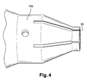
- Fig. 4 is a detailed view of a portion of an example of a second sleeve according to the preferred embodiment of the present invention.
- a device 11 for manufacturing a cellular sheath comprises a central guide 12 and a peripheral guide 13.
- the central guide 12 comprises a longitudinal channel 17 intended to receive a driver not shown on the Figures 2 and 3.
- An outer surface of the central guide 12 and an inner surface of the peripheral guide 13 define a passage 14 for receiving an insulating material in a viscous state.
- the manufacturing device 11 also comprises a first sleeve 15a, part of which is intended to be interposed between the central guide 12 and the peripheral guide 13.
- the first sleeve 15a comprises, in the preferred embodiment of the present invention, eight radial openings 16 opening on the one hand on the central guide 12, and on the other on the peripheral guide 13.
- the inner surface of the peripheral guide 13 and an outer surface of the first sleeve 15a define a peripheral path 18 for receiving the insulating material in the viscous state, so as to form a peripheral wall of the cellular sheath.
- An inner surface of the first sleeve 15a and the outer surface of the central guide 12 define a central path 19 for receiving the insulating material in the viscous state, so as to form a central wall of the honeycomb sheath.
- Such a first sleeve 15a thus makes it possible to manufacture a cellular sheath with eight closed cells.
- a second sleeve 15b may for example be used.
- the second sleeve 15b has a shape generally similar to the shape of the first sleeve 15a, but has a number of radial openings 16 distinct, so that the second sleeve 15b allows to manufacture a honeycomb sheath five cells only.
- the first sleeve 15a and the second sleeve 15b are traversed by the radial openings 16 only on a portion, typically substantially on the part intended to be effectively inserted between the central guide 13 and the peripheral guide 13.
- the manufacturing device 11 comprises two supply ducts 20 intended to receive the insulating material in the viscous state, and to guide the insulating material towards the passage 14.
- the insulating material in the viscous state then interferes with the peripheral path 18 of the passage 14, the radial openings 16 and the central path 19, so as to form the honeycomb sheath.
- the manufacturing device 11 comprises a pressure chamber 21 and a vacuum chamber 22 intended to be arranged in a longitudinal axis X of the manufacturing device 11.
- the booster chamber 21 comprises a blowing duct 23 intended to communicate with a first fitting 31, so that the booster chamber 21 can communicate with a not shown blowing duct.
- the vacuum chamber 22 includes a suction duct 24 for communicating with a second connector 32, so that the vacuum chamber 22 can communicate with a suction pipe not shown.
- the first sleeve 15a and the second sleeve 15b comprise longitudinally extending vents 25.
- the booster chamber 21 is designed to communicate with each vent 25.
- the gas inside each cell formed by the insulating material at the outlet of the sleeve thus has a pressure high enough that the cells do not collapse, now the geometry of the honeycomb sheath.
- the vacuum chamber 22 is intended to communicate with the longitudinal channel 17.
- the pressure around the conductor at the outlet of the central guide 12 is small enough so that the central wall of the the formed honeycomb sheath adheres to the conductor.
- a rod 26 makes it possible to guarantee the seal between the parts of the manufacturing device 11 communicating with the pressure chamber 21 and the parts of the manufacturing device communicating with the vacuum chamber 22.
- the rod 26 comprises a depression channel 27 intended to open on the one hand on the vacuum chamber 22, and on the other hand on the longitudinal channel 17 of the central guide 12.
- the rod 26 passes through the pressure chamber 21.
- the vacuum chamber 22, the booster chamber 21 and the rod 26 are removably attached, so that a user can easily assemble and disassemble the manufacturing device 11.
Landscapes
- Engineering & Computer Science (AREA)
- Manufacturing & Machinery (AREA)
- Insulated Conductors (AREA)
- Insulating Bodies (AREA)
- Two-Way Televisions, Distribution Of Moving Picture Or The Like (AREA)
- Superconductors And Manufacturing Methods Therefor (AREA)
- Communication Cables (AREA)
- Waveguides (AREA)
- Forging (AREA)
- Body Structure For Vehicles (AREA)
Abstract
Description
- La présente invention concerne un procédé et un dispositif de fabrication d'une gaine alvéolée d'un conducteur. Elle se rapporte plus particulièrement, mais de manière non limitative, à la fabrication de gaines diélectriques intermédiaires de câbles coaxiaux.
- La figure 1 illustre un exemple de câble coaxial selon l'art antérieur. Le câble coaxial 10 comprend généralement un conducteur central 4 entouré d'une gaine intermédiaire 5, ou isolation, réalisée en un matériau diélectrique isolant. Le conducteur central 4 peut par exemple être massif ou sous forme de toron, comme représenté sur la figure 1. Une gaine extérieure de protection 7, et éventuellement un conducteur supplémentaire 6 sous forme de tresse, de guipage ou encore de ruban, entourent la gaine intermédiaire 5.
- La gaine intermédiaire doit avoir des propriétés diélectriques spécifiques afin d'obtenir pour le câble coaxial les caractéristiques d'affaiblissement requises, notamment pour des fréquences relativement élevées. Plus précisément, on demande généralement que la gaine intermédiaire présente une constante diélectrique inférieure à 1,8 environ, et la plus proche possible de 1. Plus la constante diélectrique est proche de 1, plus le câble coaxial peut être utilisé à des fréquences élevées.
- Les constantes diélectriques des matériaux isolants classiquement utilisés en câblerie, par exemple le polyéthylène ou le polytétrafluoroéthylène (PTFE), ont plutôt une valeur voisine de 2 lorsque ces matériaux isolants sont utilisés sous une forme massive. Pour abaisser la constante diélectrique de la gaine intermédiaire, il est connu d'utiliser ces matériaux isolants pour formes des gaines cellulaires ou des gaines alvéolées.
- Les gaines cellulaires sont réalisées en un matériau isolant comprenant une pluralité de bulles remplies d'air ou d'un gaz de constante diélectrique proche de 1, de telle sorte que la constante diélectrique de la gaine cellulaire est plus faible que la constante diélectrique du matériau isolant seul.
- Les gaines alvéolées présentent des alvéoles s'étendant de manière rectiligne ou bien en hélice le long du câble coaxial. Comme représenté sur la figure 1, des parois 53, 51 et 54 permettent de séparer les alvéoles 52 les unes des autres, du conducteur central 4, et de la gaine extérieure de protection 7. Les alvéoles peuvent avoir des formes diverses.
- Les alvéoles peuvent être fermées, comme représenté sur la figure 1, c'est à dire que chaque alvéole est entièrement entourée de parois en matériau isolant.
- Les alvéoles peuvent également déboucher directement sur le conducteur.
- Les alvéoles sont obtenues par mise en forme du matériau isolant utilisé, à l'aide d'un dispositif d'extrusion présentant à cet effet des ouvertures et des passages adéquats.
- Le brevet européen EP 0 803 878 décrit un procédé et un dispositif de fabrication d'une telle gaine alvéolée. Le dispositif de fabrication comprend un guide central comprenant un canal longitudinal destiné au passage d'un conducteur. Le dispositif de fabrication comprend également une filière coaxiale entourant le guide central. Une surface extérieure du guide central et une surface intérieure de la filière définissent un passage pour un matériau isolant à l'état visqueux. La filière comprend des ouvertures communiquant avec le passage. Les ouvertures sont destinées à recevoir le matériau isolant à l'état visqueux, et ont une forme adaptée pour permettre de former des alvéoles. Le matériau isolant est ainsi mis en forme par extrusion, puis appliqué sur le conducteur à une distance de la filière telle que le matériau isolant est suffisamment étiré pour que les parois des alvéoles ne s'affaissent pas sous l'effet de la dépression à la sortie de la filière.
- La filière comprend plusieurs ouvertures, de manière à permettre la formation d'un nombre d'alvéoles typiquement compris entre 4 et 6. Une filière donnée est donc associée à une géométrie donnée de la gaine alvéolée. Pour fabriquer des gaines alvéolées de géométries variées, il est nécessaire d'utiliser plusieurs dispositifs de fabrications, ou bien de remplacer la filière d'un dispositif de fabrication donné.
- Le dispositif de fabrication de câble coaxial selon la présente invention permet de fabriquer plus facilement des câbles coaxiaux ayant des gaines alvéolées à géométries variées avec un même dispositif de fabrication.
- La présente invention a pour objet un dispositif de fabrication d'une gaine alvéolée en un matériau isolant autour d'un conducteur. Le dispositif de fabrication comprend un guide central comprenant un canal longitudinal destiné à recevoir le conducteur. Selon l'invention, le dispositif de fabrication comprend également un guide périphérique. Une surface intérieure du guide périphérique et une surface extérieure du guide central définissent un passage destiné à recevoir ledit matériau isolant dans un état visqueux. Le dispositif de fabrication comprend par ailleurs un manchon distinct du guide central et du guide périphérique. Au moins une partie du manchon est destinée à être intercalée entre le guide central et le guide périphérique et comprend au moins une ouverture débouchant sur le guide central d'une part et sur le guide périphérique d'autre part.
- Lorsqu'un même dispositif de fabrication est utilisé pour fabriquer des gaines alvéolées ayant des géométries variées, seul le manchon est remplacé. Le dispositif de fabrication selon la présente invention offre donc une plus grande modularité que les dispositifs selon l'art antérieur.
- Chaque ouverture du manchon communique avec le passage et est donc également destinée à recevoir du matériau isolant à l'état visqueux, de façon à former une paroi en matériau isolant.
- Le manchon comprend avantageusement plusieurs ouvertures, de façon à former plusieurs parois séparant plusieurs alvéoles les unes des autres.
- Alternativement, le manchon comprend une seule ouverture.
- Classiquement, mais de manière non limitative, une surface extérieure du manchon et la surface intérieure du guide périphérique définissent un chemin périphérique destiné à recevoir le matériau isolant à l'état visqueux, de telle sorte que les alvéoles ainsi formées sont séparées d'une gaine extérieure au moins par une paroi périphérique correspondant au chemin périphérique.
- Une surface intérieure du manchon et la surface extérieure du guide central définissent avantageusement un chemin central destiné à recevoir le matériau isolant à l'état visqueux, lorsque le manchon est intercalé entre le guide central et le guide périphérique.
- Le matériau isolant à l'état visqueux reçu dans le chemin central forme ainsi une paroi centrale isolant au moins une alvéole du conducteur. Les alvéoles ainsi formées sont fermées.
- Alternativement, le manchon peut avoir des dimensions telles que lorsque le manchon est au moins partiellement intercalé entre le guide central et le guide périphérique, la surface intérieure du manchon et la surface extérieure du guide central sont suffisamment rapprochées pour que le matériau isolant à l'état visqueux ne s'immisce pas entre le manchon et le guide central. Un tel manchon permet de fabriquer des câbles coaxiaux dans lesquels les alvéoles de la gaine alvéolée débouchent directement sur le conducteur.
- De manière générale, le manchon peut avoir des formes variées.
- Classiquement, le manchon comprend plusieurs ouvertures radiales, de façon à former des parois radiales séparant les alvéoles les unes des autres. Une telle gaine alvéolée aura grossièrement une forme en roue de vélo.
- Comme chaque ouverture radiale du manchon débouche sur une surface extérieure du manchon, les manchons selon la présente invention sont relativement plus faciles à fabriquer que les filières de l'art antérieur.
- Alternativement, le manchon peut comprendre une pièce centrale et une pièce périphérique coaxiales. Une surface extérieure de la pièce centrale et une surface intérieure de la pièce périphérique définissent un chemin intermédiaire. La pièce centrale et la pièce périphérique comprennent chacune au moins une ouverture radiale, et de préférence plusieurs. Les ouvertures radiales de la pièce centrale débouchent sur le guide central d'une part et sur la pièce périphérique d'autre part. Les ouvertures radiales de la pièce périphérique débouchent sur la pièce centrale d'une part et sur le guide périphérique de l'autre. Le chemin intermédiaire, les ouvertures radiales de la pièce centrale et les ouvertures radiales de la pièce périphérique sont ainsi destinés à recevoir du matériau isolant à l'état visqueux, de façon à former deux couches d'alvéoles. Les alvéoles sont séparées entre elles par une paroi intermédiaire correspondant au chemin intermédiaire, et par des parois radiales correspondant aux ouvertures radiales de la pièce centrale et de la pièce périphérique, formant ainsi une gaine alvéolée dite à double couche.
- La présente invention n'est pas limitée par le nombre de couches d'alvéoles de la gaine alvéolée.
- Alternativement, le manchon peut comprendre une pluralité d'ouvertures non rectilignes et s'entrecroisant les unes les autres, de façon à ce que les alvéoles ainsi formées aient une sensiblement une forme d'hexagone ou de portion d'hexagone. Une telle gaine alvéolée est dite à nids d'abeille.
- Alternativement, le dispositif de fabrication de la gaine alvéolée peut comprendre plus d'un guide central, de telle sorte que le câble coaxial ainsi fabriqué comprenne par exemple deux conducteurs sensiblement parallèles. Dans ce cas, le dispositif de fabrication peut comprendre un seul guide périphérique. Le passage est défini par les surfaces extérieures des guides centraux et par la surface intérieure du guide périphérique. Le manchon a une forme adaptée pour recevoir les guides centraux, de façon à pouvoir être intercalé entre les guides centraux et le guide périphérique. Le manchon comprend au moins une ouverture débouchant sur un des guides centraux et sur le guide périphérique. Le manchon peut également comprendre un chemin débouchant de part et d'autres sur les guides centraux.
- On comprendra que la présente invention n'est pas limitée par le nombre, la forme, ni la disposition de la ou des ouvertures du manchon, ni par la forme du manchon lui-même.
- Par ailleurs, le manchon peut être en rotation relativement lente autour d'un axe longitudinal, et par rapport au guide central, de façon à former une gaine alvéolée présentant des alvéoles s'étendant hélicoïdalement le long du câble coaxial.
- Toutefois, le manchon n'est de préférence pas en rotation autour de l'axe longitudinal, de façon à former des alvéoles s'étendant de manière rectiligne le long du câble coaxial.
- Le dispositif de fabrication selon la présente invention comprend avantageusement une chambre de dépression destinée à communiquer d'une part avec une canalisation d'aspiration, et d'autre part avec le canal longitudinal du guide central, de telle sorte qu'en sortie du guide central, le matériau isolant soit appliqué contre le conducteur.
- La chambre de dépression permet d'assurer une dépression à la sortie du guide central, sous l'effet de laquelle la paroi centrale est appliquée contre le conducteur.
- La présente invention n'est toutefois pas limitée par la présence de la chambre de dépression, ni par un quelconque procédé d'aspiration pour assurer une dépression à la sortie du guide central.
- Le manchon comprend de préférence au moins un évent s'étendant longitudinalement, et permettant d'équilibrer au moins partiellement les pressions entre chaque extrémité du manchon.
- Le manchon comprend classiquement autant d'évents que d'ouvertures radiales, de telle sorte que la pression à la sortie du manchon, dans chaque alvéole soit relativement élevée. Les évents permettent ainsi d'éviter un effondrement des parois des alvéoles sous l'effet de la dépression.
- La présente invention n'est bien entendu pas limitée par la présence d'évents. Par exemple, le matériau isolant mis en forme par extrusion peut être appliqué sur le conducteur à une distance telle que le matériau isolant est relativement étiré et refroidi.
- Le dispositif de fabrication selon la présente invention comprend avantageusement une chambre de surpression destinée à communiquer d'une part avec une canalisation de soufflage, et d'autre part avec chaque évent.
- La chambre de surpression permet d'assurer une surpression à l'intérieur des alvéoles afin d'éviter tout effondrement des parois des alvéoles.
- La présente invention n'est bien entendu pas limité par la présence de la chambre de surpression, ni par un quelconque procédé de soufflage à l'intérieur des alvéoles.
- La chambre de dépression et la chambre de surpression sont avantageusement destinées à être disposées dans un axe longitudinal du dispositif de fabrication. Avantageusement, le dispositif de fabrication comprend par ailleurs une canne comprenant un canal de dépression destiné à déboucher d'une part sur la chambre de dépression, et d'autre part sur le canal longitudinal du guide central.
- Un tel dispositif de fabrication d'une gaine alvéolée est relativement compact et s'étend selon une direction longitudinale.
- La canne permet de garantir l'étanchéité entre les pièces du dispositif de fabrication communiquant avec la chambre de surpression et les pièces du dispositif de fabrication communiquant avec la chambre de dépression.
- De plus, la chambre de dépression et la chambre de surpression sont avantageusement fixées de manière amovible, par exemple par emboîtement, de telle sorte qu'un utilisateur peut aisément monter et démonter le dispositif de fabrication.
- La présente invention n'est bien entendu pas limitée par le positionnement de la chambre de dépression et de la chambre de surpression, ni par la manière dont l'étanchéité est garantie. Un dispositif de fabrication comprenant la canne présente toutefois l'avantage d'être relativement facile à monter et/ou démonter.
- La chambre de surpression est avantageusement placée entre la chambre de dépression et une tête du dispositif de fabrication comprenant le guide central. La canne traverse avantageusement la chambre de surpression.
- Alternativement, la chambre de dépression est placée entre la chambre de surpression et la tête du dispositif de fabrication.
- La présente invention a également pour objet un dispositif de fabrication d'une gaine alvéolée autour d'un conducteur. Le dispositif de fabrication comprend un guide central comprenant un canal longitudinal destiné à recevoir le conducteur, ainsi que des moyens de mise en forme destinés à être disposés autour du guide central. Les moyens de mise en forme comprennent au moins une ouverture destinée à recevoir du matériau isolant dans un état visqueux, et au moins une partie pleine destinée à former au moins une alvéole. Chaque partie pleine comprend un évent. Le dispositif de fabrication comprend par ailleurs une chambre de dépression et une chambre de surpression. La chambre de dépression est destinée à communiquer d'une part avec une canalisation d'aspiration, et d'autre part avec le canal longitudinal, de telle sorte qu'en sortie du guide central, le matériau isolant soit appliqué contre le conducteur. La chambre de surpression est destinée à communiquer d'une part avec une canalisation de soufflage, et d'autre part avec chaque évent. La chambre de dépression et la chambre de surpression sont destinées à être disposées dans un axe longitudinal du dispositif de fabrication. Avantageusement, le dispositif de fabrication comprend par ailleurs une canne comprenant un canal de dépression destiné à déboucher d'une part sur la chambre de dépression, et d'autre part sur le canal longitudinal du guide central.
- Un tel dispositif, associant aspiration et soufflage, respectivement à la sortie du guide central et à la sortie des moyens de mise en forme, permet de garantir l'adhérence du matériau isolant sur le conducteur et d'éviter que les alvéoles ne s'affaissent, c'est à dire que ce dispositif de fabrication permet de contrôler le comportement du matériau isolant à la sortie du guide central et à la sortie des moyens de mise en forme.
- De plus, la canne permet un positionnement de la chambre de dépression et de la chambre d'aspiration dans l'axe longitudinal. La chambre de dépression et la chambre de surpression sont typiquement disposées l'une derrière l'autre, la canne permettant de garantir l'étanchéité.
- Les moyens de mise en forme peuvent comprendre un guide périphérique et un manchon. Une partie du manchon est destinée à être intercalée entre le guide central et le guide périphérique et comprend la ou les parties pleines destinées à former la ou les alvéoles, ainsi que une ou des ouvertures destinées à recevoir le matériau isolant à l'état visqueux. Le matériau isolant à l'état visqueux est également reçu dans un chemin périphérique entre le guide périphérique et le manchon, et éventuellement dans un chemin central entre le manchon et le guide central.
- Alternativement, les moyens de mise en forme comprennent une filière présentant la ou les ouvertures destinées à recevoir le matériau isolant à l'état visqueux.
- La présente invention a également pour objet un procédé de fabrication d'une gaine alvéolée autour d'un conducteur mettant en oeuvre le dispositif de fabrication selon l'invention. Le procédé selon l'invention comprend une étape d'aspiration au niveau de la canalisation d'aspiration, et une étape de soufflage au niveau de la canalisation de soufflage, l'étape d'aspiration et l'étape de soufflage ayant lieu conjointement.
- L'invention est décrite ci-après plus en détail à l'aide de figures ne représentant qu'un mode de réalisation préféré de l'invention.
- La figure 1, déjà commentée, illustre un exemple de câble coaxial.
- La figure 2 est une vue d'une section d'un exemple de dispositif de fabrication d'une gaine alvéolée selon un mode de réalisation préféré de la présente invention.
- La figure 3 est une vue en coupe d'un exemple de dispositif de fabrication d'une gaine alvéolée selon le mode de réalisation préféré de la présente invention.
- La figure 4 est une vue détaillée d'une partie d'un exemple d'un second manchon selon le mode de réalisation préféré de la présente invention.
- On notera que des éléments ou parties identiques ou similaires ont été désignés par les mêmes signes de référence sur les figures 2, 3 et 4.
- Selon le mode de réalisation préféré de la présente invention, un dispositif de fabrication 11 d'une gaine alvéolée comprend un guide central 12 et un guide périphérique 13. Le guide central 12 comprend un canal longitudinal 17 destiné à recevoir un conducteur non représenté sur les figures 2 et 3. Une surface extérieure du guide central 12 et une surface intérieure du guide périphérique 13 définissent un passage 14 destiné à recevoir un matériau isolant dans un état visqueux. Le dispositif de fabrication 11 comprend par ailleurs un premier manchon 15a dont une partie est destinée à être intercalée entre le guide central 12 et le guide périphérique 13.
- Le premier manchon 15a comprend, dans le mode de réalisation préféré de la présente invention, huit ouvertures radiales 16 débouchant d'une part sur le guide central 12, et de l'autre sur le guide périphérique 13.
- La surface intérieure du guide périphérique 13 et une surface extérieure du premier manchon 15a définissent un chemin périphérique 18 destiné à recevoir le matériau isolant à l'état visqueux, de façon à former une paroi périphérique de la gaine alvéolée.
- Une surface intérieure du premier manchon 15a et la surface extérieure du guide central 12 définissent un chemin central 19 destiné à recevoir le matériau isolant à l'état visqueux, de façon à former une paroi centrale de la gaine alvéolée.
- Un tel premier manchon 15a permet ainsi de fabriquer une gaine alvéolée à huit alvéoles fermées.
- Lorsqu'un utilisateur non représenté désire fabriquer une gaine alvéolée ayant une géométrie différente de la géométrie de la gaine alvéolée associée au premier manchon 15a des figures 2 et 3, l'utilisateur remplace le premier manchon 15a. Un second manchon 15b, illustré partiellement sur la figure 4, peut par exemple être utilisé.
- Le second manchon 15b a une forme globalement similaire à la forme du premier manchon 15a, mais présente un nombre d'ouvertures radiales 16 distinct, de telle sorte que le second manchon 15b permet de fabriquer une gaine alvéolée à cinq alvéoles seulement.
- Le premier manchon 15a et le second manchon 15b sont traversés par les ouvertures radiales 16 seulement sur une portion, typiquement sensiblement sur la partie destinée à être effectivement intercalée entre le guide central 13 et le guide périphérique 13.
- Comme représenté sur la figure 3, le dispositif de fabrication 11 comprend deux conduits d'alimentation 20 destinés à recevoir le matériau isolant à l'état visqueux, et à guider le matériau isolant vers le passage 14. Le matériau isolant à l'état visqueux s'immisce ensuite par le chemin périphérique 18 du passage 14, les ouvertures radiales 16 et le chemin central 19, de façon à former la gaine alvéolée.
- Le dispositif de fabrication 11 selon le mode de réalisation préféré de la présente invention comprend une chambre de surpression 21 et une chambre de dépression 22 destinées à être disposées dans un axe longitudinal X du dispositif de fabrication 11.
- La chambre de surpression 21 comprend un conduit de soufflage 23 destiné à communiquer avec un premier raccord 31, de façon à ce que la chambre de surpression 21 puisse communiquer avec une canalisation de soufflage non représentée.
- La chambre de dépression 22 comprend un conduit d'aspiration 24 destiné à communiquer avec un second raccord 32, de façon à ce que la chambre de dépression 22 puisse communiquer avec une canalisation d'aspiration non représentée.
- Le premier manchon 15a et le second manchon 15b comprennent des évents 25 s'étendant longitudinalement. La chambre de surpression 21 est destinée à communiquer avec chaque évent 25. Lorsque la chambre de surpression 21 est également connectée à la canalisation de soufflage, le gaz à l'intérieur de chaque alvéole formée par le matériau isolant en sortie du manchon a ainsi une pression suffisamment élevée pour que les alvéoles ne s'effondrent pas, maintenant par-là la géométrie de la gaine alvéolée.
- La chambre de dépression 22 est destinée à communiquer avec le canal longitudinal 17. Lorsque la chambre de dépression 22 est connectée à la canalisation d'aspiration, la pression autour du conducteur en sortie du guide central 12 est suffisamment faible pour que la paroi centrale de la gaine alvéolée formée adhère au conducteur.
- Une canne 26 permet de garantir l'étanchéité entre les pièces du dispositif de fabrication 11 communiquant avec la chambre de surpression 21 et les pièces du dispositif de fabrication communiquant avec la chambre de dépression 22.
- La canne 26 comprend un canal de dépression 27 destiné à déboucher d'une part sur la chambre de dépression 22, et d'autre part sur le canal longitudinal 17 du guide central 12. La canne 26 traverse la chambre de surpression 21.
- La chambre de dépression 22, la chambre de surpression 21 et la canne 26 sont fixées de manière amovible, de telle sorte qu'un utilisateur peut aisément monter et démonter le dispositif de fabrication 11.
Claims (8)
- Dispositif de fabrication (11) d'une gaine alvéolée en un matériau isolant autour d'un conducteur, le dispositif de fabrication comprenant :un guide central (12) comprenant un canal longitudinal (17) destiné à recevoir le conducteur,le dispositif de fabrication étant caractérisé en ce qu'il comprendun guide périphérique (13), une surface intérieure du guide périphérique et une surface extérieure du guide central définissant un passage (14) destiné à recevoir ledit matériau isolant dans un état visqueux,un manchon (15a) distinct du guide central et du guide périphérique, au moins une partie du manchon étant destinée à être intercalée entre le guide central et le guide périphérique et comprenant au moins une ouverture débouchant sur le guide central d'une part et sur le guide périphérique d'autre part.
- Dispositif de fabrication (11) selon la revendication 1, dans lequel
une surface intérieure du manchon (15a, 15b) et la surface extérieure du guide central (12) définissent un chemin central (19) destiné à recevoir le matériau isolant à l'état visqueux, lorsque le manchon est intercalé entre le guide central et le guide périphérique (13). - Dispositif de fabrication (11) d'une gaine alvéolée selon l'une des revendications 1 ou 2, comprenant par ailleurs :une chambre de dépression (22) destinée à communiquer d'une part avec une canalisation d'aspiration, et d'autre part avec le canal longitudinal (17) du guide central (12), de telle sorte qu'en sortie du guide central, le matériau isolant soit appliqué contre le conducteur.
- Dispositif de fabrication (11) d'une gaine alvéolée selon l'une des revendications 1 à 3, dans lequel
le manchon (15a, 15b) comprend au moins un évent (25) s'étendant longitudinalement, et permettant d'équilibrer au moins partiellement les pressions entre chaque extrémité du manchon. - Dispositif de fabrication (11) d'une gaine alvéolée selon la revendication 4, comprenant par ailleurs
une chambre de surpression (21) destinée à communiquer d'une part avec une canalisation de soufflage, et d'autre part avec chaque évent (25). - Dispositif de fabrication (11) d'une gaine alvéolée selon les revendications 3, 4 et 5, dans lequel
la chambre de dépression (22) et la chambre de surpression (21) sont destinés à être disposés coaxialement à un axe longitudinal du dispositif de fabrication,
le dispositif de fabrication comprenant par ailleurs
une canne (26) comprenant un canal de dépression (27) destiné à déboucher d'une part sur la chambre de dépression, et d'autre part sur le canal longitudinal (17) du guide central (12). - Dispositif de fabrication (11) d'une gaine alvéolée selon la revendication 6, dans lequel
la canne (26) traverse la chambre de surpression (21). - Procédé de fabrication d'une gaine alvéolée mettant en oeuvre le dispositif (11) selon l'une des revendications 6 ou 7, et comprenant
une étape d'aspiration au niveau de la canalisation d'aspiration, et
une étape de soufflage au niveau de la canalisation de soufflage, l'étape d'aspiration et l'étape de soufflage ayant lieu conjointement.
Applications Claiming Priority (1)
| Application Number | Priority Date | Filing Date | Title |
|---|---|---|---|
| FR0451926A FR2874736B1 (fr) | 2004-08-27 | 2004-08-27 | Dispositif de fabrication d'une gaine alveolee autour d'un conducteur |
Publications (2)
| Publication Number | Publication Date |
|---|---|
| EP1630829A1 true EP1630829A1 (fr) | 2006-03-01 |
| EP1630829B1 EP1630829B1 (fr) | 2007-07-04 |
Family
ID=34949166
Family Applications (1)
| Application Number | Title | Priority Date | Filing Date |
|---|---|---|---|
| EP05300689A Expired - Lifetime EP1630829B1 (fr) | 2004-08-27 | 2005-08-23 | Dispositif de fabrication d'une gaine alvéolée autour d'un conducteur |
Country Status (6)
| Country | Link |
|---|---|
| US (1) | US20060288568A1 (fr) |
| EP (1) | EP1630829B1 (fr) |
| KR (1) | KR20060050654A (fr) |
| AT (1) | ATE366457T1 (fr) |
| DE (1) | DE602005001534T2 (fr) |
| FR (1) | FR2874736B1 (fr) |
Cited By (2)
| Publication number | Priority date | Publication date | Assignee | Title |
|---|---|---|---|---|
| FR2919750A1 (fr) * | 2007-08-02 | 2009-02-06 | Axon Cable Soc Par Actions Sim | Cable coaxial a faible constante dielectrique, et ses procede et outil de fabrication |
| FR2938111A1 (fr) * | 2008-11-06 | 2010-05-07 | Axon Cable Sa | Fil electrique a gaine de ptfe a faible constante dielectrique, et ses procede et outil de fabrication |
Families Citing this family (3)
| Publication number | Priority date | Publication date | Assignee | Title |
|---|---|---|---|---|
| KR20140015462A (ko) | 2011-04-12 | 2014-02-06 | 티코나 엘엘씨 | 연속 섬유 보강된 열가소성 봉 및 그를 제조하기 위한 인발 방법 |
| TW201303192A (zh) | 2011-04-12 | 2013-01-16 | Ticona Llc | 用於水下應用之臍管 |
| US9012781B2 (en) | 2011-04-12 | 2015-04-21 | Southwire Company, Llc | Electrical transmission cables with composite cores |
Citations (1)
| Publication number | Priority date | Publication date | Assignee | Title |
|---|---|---|---|---|
| EP0803878A1 (fr) * | 1996-04-23 | 1997-10-29 | Filotex | Procédé et dispositif de fabrication d'une gaine aérée en un matériau isolant autour d'un conducteur, et câble coaxial muni d'une telle gaine |
Family Cites Families (54)
| Publication number | Priority date | Publication date | Assignee | Title |
|---|---|---|---|---|
| BE504311A (fr) * | 1950-06-30 | 1900-01-01 | ||
| US3229012A (en) * | 1962-05-28 | 1966-01-11 | Gen Cable Corp | Method and apparatus for extruding laminar wall |
| GB967567A (en) * | 1962-07-18 | 1964-08-26 | Ass Elect Ind | Improvements relating to electric cables with extruded insulant |
| US3479425A (en) * | 1965-07-22 | 1969-11-18 | Dow Chemical Co | Extrusion method |
| GB1291880A (en) * | 1969-12-09 | 1972-10-04 | British Insulated Callenders | Improvements in or relating to the manufacture of insulated electric cables |
| US3771934A (en) * | 1969-02-18 | 1973-11-13 | Int Standard Electric Corp | Apparatus for extending water-blocked cartwheel cable |
| US3905853A (en) * | 1970-05-21 | 1975-09-16 | Creators Ltd | Reinforced plastics tubes |
| US4468435C1 (en) * | 1973-08-21 | 2001-06-12 | Sumitomo Electric Industries | Process for the production of highly expanded polyolefin insulated wires and cables |
| ES217858Y (es) * | 1974-12-20 | 1977-01-01 | Industrie Pirelli, S. P. A. | Cabeza de trefiladora para extruir material plastomero o elastomero alrededor de filamentos. |
| US4132756A (en) * | 1974-12-20 | 1979-01-02 | Industrie Pirelli, S.P.A. | Process for extruding plastomeric or elastomeric material on filaments |
| US4029458A (en) * | 1975-06-24 | 1977-06-14 | The B.F. Goodrich Company | Extrusion die |
| US4093414A (en) * | 1976-09-16 | 1978-06-06 | General Cable Corporation | Single die co-extrusion apparatus for insulation |
| FI53522C (fi) * | 1976-10-18 | 1978-05-10 | Nokia Oy Ab | Foerfarande foer tillverkning av hoegspaenningsplastkabel |
| US4081232A (en) * | 1977-02-08 | 1978-03-28 | The Anaconda Company | Fixed center tooling for an extruder that provides for concentric layers of coating material |
| JPS5484288A (en) * | 1977-12-16 | 1979-07-05 | Sumitomo Electric Ind Ltd | Manufacturing process of insulated wire with foamed plastics |
| US4166881A (en) * | 1977-12-27 | 1979-09-04 | Western Electric Company | Top coated PVC articles |
| US4212612A (en) * | 1979-07-05 | 1980-07-15 | Western Electric Company, Inc. | Apparatus for enclosing a plurality of conductors in a partitioned jacket |
| US4303734A (en) * | 1979-12-06 | 1981-12-01 | Southwire Company | Multiple layer extrusion tooling having a tip enabling extrusion of one layer onto a substrate at a point outside of the extrusion head |
| US4525131A (en) * | 1983-08-29 | 1985-06-25 | Alcan Aluminum Corporation | Cable-coating extruder head system with changeable die and guider elements |
| US4568507A (en) * | 1983-12-27 | 1986-02-04 | Northern Telecom Limited | Jacketing of telecommunications cable cores |
| US4563540A (en) * | 1984-06-29 | 1986-01-07 | At&T Technologies, Inc. | Bonded sheath cable |
| DE3424269C2 (de) * | 1984-06-30 | 1994-01-27 | Krupp Ag | Vorrichtung zum Herstellen von armierten Profilen und verstärkten Schläuchen |
| US4623504A (en) * | 1984-10-22 | 1986-11-18 | Smith Larry F | Method and apparatus for making post-tensioning tendons for concrete |
| DE3447225C1 (de) * | 1984-12-22 | 1986-02-06 | Kabelwerke Reinshagen Gmbh, 5600 Wuppertal | Schwimmfaehige,flexible elektrische und/oder optische Leitung |
| DE3617652A1 (de) * | 1986-05-26 | 1987-12-03 | Troester Maschf Paul | Extruderanlage zum ummanteln eines strangfoermigen produktes, insbesondere eines kabels |
| US5115485A (en) * | 1987-05-04 | 1992-05-19 | Rochester Corporation | Cable for housing parallelly oriented optical fibers and method and apparatus for producing the same |
| CH678239A5 (fr) * | 1987-05-29 | 1991-08-15 | Maillefer Sa | |
| US4789589A (en) * | 1988-01-19 | 1988-12-06 | Northern Telecom Limited | Insulated electrical conductor wire and method for making same |
| US4999148A (en) * | 1989-08-24 | 1991-03-12 | Northern Telecom Limited | Method and apparatus for making reinforced insulated electrical conductor |
| US5183669A (en) * | 1991-05-28 | 1993-02-02 | Guillemette A Roger | Deflector for crosshead extruder |
| US5215698A (en) * | 1991-11-25 | 1993-06-01 | Americraft Machined Products, Inc. | Extrusion tool and method of extrusion coating |
| FR2710286B1 (fr) * | 1993-09-22 | 1995-12-08 | Plastic Omnium Cie | Corps creux en résine fluorée, procédé pour sa fabrication et presse à extruder pour la mise en Óoeuvre du procédé. |
| DE69433383T2 (de) * | 1993-10-01 | 2004-10-07 | Target Therapeutics Inc | Mehrpoliger katheter und mehrpoliger führungsdraht zur messung der elektrischen herzaktivität |
| US5667818A (en) * | 1993-11-05 | 1997-09-16 | Guillemette; A. Roger | Extrusion system with balanced flow passage |
| US5853770A (en) * | 1993-11-05 | 1998-12-29 | Guillemette; Arthur Roger | Coextrusion die component system |
| US5980226A (en) * | 1993-11-05 | 1999-11-09 | Guillemette; A. Roger | Modular die assembly |
| US5920032A (en) * | 1994-12-22 | 1999-07-06 | Baker Hughes Incorporated | Continuous power/signal conductor and cover for downhole use |
| US5912023A (en) * | 1995-10-17 | 1999-06-15 | Yamashita Rubber Kabushiki Kaisha | Method of manufacturing and a manufacturing device of reinforced hose |
| US5665164A (en) * | 1996-01-02 | 1997-09-09 | Milliman; James A. | Co-extrusion cross-head die apparatus |
| DE19700723C2 (de) * | 1997-01-11 | 2002-02-14 | Keicher Engineering Gmbh | Extruder |
| US5965074A (en) * | 1997-02-17 | 1999-10-12 | E.I. Du Pont De Nemours And Company | Continuous paste extrusion method |
| US6382944B1 (en) * | 1998-11-10 | 2002-05-07 | Guill Tool & Engineering Co., Inc. | Universally mounted adjustable die |
| US6902388B2 (en) * | 1998-11-10 | 2005-06-07 | Guill Tool And Engineering Co., Inc. | Pivotally adjustable die |
| US6573456B2 (en) * | 1999-01-11 | 2003-06-03 | Southwire Company | Self-sealing electrical cable having a finned inner layer |
| US6534715B1 (en) * | 1999-08-30 | 2003-03-18 | Pirelli Cavi E Sistemi S.P.A. | Electrical cable with self-repairing protection and apparatus for manufacturing the same |
| US7056110B2 (en) * | 2001-10-08 | 2006-06-06 | Bridgestone/Firestone North American Tire, Llc | Apparatus for making reinforcement ply material |
| US7290999B2 (en) * | 2002-03-21 | 2007-11-06 | Nestec S.A. | Extrusion die plate and cutter assembly with hydraulic motor |
| US7214880B2 (en) * | 2002-09-24 | 2007-05-08 | Adc Incorporated | Communication wire |
| US20050139377A1 (en) * | 2003-12-31 | 2005-06-30 | Levy Daniel N. | Paste extruded insulator with air channels |
| US7329113B2 (en) * | 2004-03-19 | 2008-02-12 | Leseman Steven R | Adjustable extrusion die |
| DE102004028100B4 (de) * | 2004-06-09 | 2009-09-17 | Thermo-Technik-Systeme Gmbh | Extrusionsblaskopf |
| JP2006004820A (ja) * | 2004-06-18 | 2006-01-05 | Yazaki Corp | 同軸ケーブル用シールド端子 |
| JP4295688B2 (ja) * | 2004-07-09 | 2009-07-15 | 矢崎総業株式会社 | 電線保護キャップ用の成形型 |
| US7271344B1 (en) * | 2006-03-09 | 2007-09-18 | Adc Telecommunications, Inc. | Multi-pair cable with channeled jackets |
-
2004
- 2004-08-27 FR FR0451926A patent/FR2874736B1/fr not_active Expired - Fee Related
-
2005
- 2005-08-11 US US11/203,421 patent/US20060288568A1/en not_active Abandoned
- 2005-08-23 AT AT05300689T patent/ATE366457T1/de not_active IP Right Cessation
- 2005-08-23 DE DE602005001534T patent/DE602005001534T2/de not_active Expired - Lifetime
- 2005-08-23 EP EP05300689A patent/EP1630829B1/fr not_active Expired - Lifetime
- 2005-08-25 KR KR1020050078312A patent/KR20060050654A/ko not_active Withdrawn
Patent Citations (1)
| Publication number | Priority date | Publication date | Assignee | Title |
|---|---|---|---|---|
| EP0803878A1 (fr) * | 1996-04-23 | 1997-10-29 | Filotex | Procédé et dispositif de fabrication d'une gaine aérée en un matériau isolant autour d'un conducteur, et câble coaxial muni d'une telle gaine |
Cited By (5)
| Publication number | Priority date | Publication date | Assignee | Title |
|---|---|---|---|---|
| FR2919750A1 (fr) * | 2007-08-02 | 2009-02-06 | Axon Cable Soc Par Actions Sim | Cable coaxial a faible constante dielectrique, et ses procede et outil de fabrication |
| US8007700B2 (en) | 2007-08-02 | 2011-08-30 | Axon'cable | Coaxial cable of low dielectric constant, and a fabrication method and tool therefor |
| FR2938111A1 (fr) * | 2008-11-06 | 2010-05-07 | Axon Cable Sa | Fil electrique a gaine de ptfe a faible constante dielectrique, et ses procede et outil de fabrication |
| EP2184744A1 (fr) * | 2008-11-06 | 2010-05-12 | Axon'cable | Fil électrique à gaine de PTFE robuste et à faible constante diélectrique, et ses procédé et outil de fabrication |
| US8618417B2 (en) | 2008-11-06 | 2013-12-31 | Axon'cable | Electric wire having a PTFE covering that is robust and that has a low dielectric constant, and a method and a tool for manufacturing the same |
Also Published As
| Publication number | Publication date |
|---|---|
| US20060288568A1 (en) | 2006-12-28 |
| FR2874736B1 (fr) | 2006-11-03 |
| DE602005001534T2 (de) | 2008-03-20 |
| ATE366457T1 (de) | 2007-07-15 |
| KR20060050654A (ko) | 2006-05-19 |
| EP1630829B1 (fr) | 2007-07-04 |
| FR2874736A1 (fr) | 2006-03-03 |
| DE602005001534D1 (de) | 2007-08-16 |
Similar Documents
| Publication | Publication Date | Title |
|---|---|---|
| EP0803878B1 (fr) | Procédé et dispositif de fabrication d'une gaine aérée en un matériau isolant autour d'un conducteur, et câble coaxial muni d'une telle gaine | |
| EP0027252B1 (fr) | Dispositif pour la fabrication de corps à structure alvéolaire par extrusion d'une matière céramique, et procédé de fabrication dudit dispositif | |
| EP4124595A1 (fr) | Machine de soufflage | |
| WO2014072609A1 (fr) | Buse laser à élément mobile externe | |
| EP1630829B1 (fr) | Dispositif de fabrication d'une gaine alvéolée autour d'un conducteur | |
| BE1021454B1 (fr) | Dispositif de fabrication de zones de poils pour des brosses. | |
| EP0236645B2 (fr) | Appareillage et procédé pour l'extrusion de tubes plastiques à parois composites | |
| EP4124701B1 (fr) | Tuyau d'une machine de soufflage, machine de soufflage et procédé d'isolation | |
| EP3188883A1 (fr) | Moule pour machine de soufflage et machine de soufflage equipee d'un tel moule | |
| EP0750449A1 (fr) | Tête de torche à plasma et torche à plasma la comportant | |
| FR3066415B1 (fr) | Dispositif d'ejection pneumatique et machine de tri comportant un tel dispositif | |
| EP3823805A1 (fr) | Procédé de réalisation d'un élément moulant avec fente d'évacuation d'air | |
| FR2740070A1 (fr) | Systeme de barre de retournement a pression differentielle | |
| EP4321323A1 (fr) | Extrudeuse pour l'extrusion d'une couche électriquement isolante comprenant une vis d'extrusion ayant un canal d'injection de liquide | |
| EP2512734B1 (fr) | Appareil de lustrage a air comprime dote d'un moyen de refroidissement | |
| EP3823804B1 (fr) | Procede de realisation d'un element moulant comprenant un moyen d'eventation | |
| EP3729570B1 (fr) | Dispositif pour denuder un cable | |
| FR3117398A1 (fr) | Installation d’extrusion améliorée pour la fabrication de bande de profilé | |
| FR2937896A1 (fr) | Procede et dispositif d'extrusion simultanee de deux tubes en materiau synthetique | |
| EP3787865B1 (fr) | Element moulant avec fente d'evacuation de l'air et secteur de micro-moulage | |
| EP3324091A1 (fr) | Dispositif de raccordement pour acheminer un fluide, et procedes d'utilisation et de remplissage s'y rapportant | |
| FR2640765A1 (fr) | Dispositif de manipulation d'un miroir reflechissant la lumiere | |
| EP0938100A1 (fr) | Câble de transmission à haute fréquence à deux groupes de conducteurs | |
| CA3188082A1 (fr) | Ensemble pour l'aspiration de poussieres | |
| FR2519436A2 (fr) | Valve de regulation de la pression d'un fluide |
Legal Events
| Date | Code | Title | Description |
|---|---|---|---|
| PUAI | Public reference made under article 153(3) epc to a published international application that has entered the european phase |
Free format text: ORIGINAL CODE: 0009012 |
|
| AK | Designated contracting states |
Kind code of ref document: A1 Designated state(s): AT BE BG CH CY CZ DE DK EE ES FI FR GB GR HU IE IS IT LI LT LU LV MC NL PL PT RO SE SI SK TR |
|
| AX | Request for extension of the european patent |
Extension state: AL BA HR MK YU |
|
| 17P | Request for examination filed |
Effective date: 20060901 |
|
| AKX | Designation fees paid |
Designated state(s): AT BE BG CH CY CZ DE DK EE ES FI FR GB GR HU IE IS IT LI LT LU LV MC NL PL PT RO SE SI SK TR |
|
| GRAP | Despatch of communication of intention to grant a patent |
Free format text: ORIGINAL CODE: EPIDOSNIGR1 |
|
| GRAS | Grant fee paid |
Free format text: ORIGINAL CODE: EPIDOSNIGR3 |
|
| GRAA | (expected) grant |
Free format text: ORIGINAL CODE: 0009210 |
|
| AK | Designated contracting states |
Kind code of ref document: B1 Designated state(s): AT BE BG CH CY CZ DE DK EE ES FI FR GB GR HU IE IS IT LI LT LU LV MC NL PL PT RO SE SI SK TR |
|
| REG | Reference to a national code |
Ref country code: GB Ref legal event code: FG4D Free format text: NOT ENGLISH |
|
| REG | Reference to a national code |
Ref country code: CH Ref legal event code: EP |
|
| REG | Reference to a national code |
Ref country code: IE Ref legal event code: FG4D Free format text: LANGUAGE OF EP DOCUMENT: FRENCH |
|
| REF | Corresponds to: |
Ref document number: 602005001534 Country of ref document: DE Date of ref document: 20070816 Kind code of ref document: P |
|
| GBT | Gb: translation of ep patent filed (gb section 77(6)(a)/1977) |
Effective date: 20070905 |
|
| REG | Reference to a national code |
Ref country code: CH Ref legal event code: NV Representative=s name: CRONIN INTELLECTUAL PROPERTY |
|
| REG | Reference to a national code |
Ref country code: SE Ref legal event code: TRGR |
|
| PG25 | Lapsed in a contracting state [announced via postgrant information from national office to epo] |
Ref country code: BG Free format text: LAPSE BECAUSE OF FAILURE TO SUBMIT A TRANSLATION OF THE DESCRIPTION OR TO PAY THE FEE WITHIN THE PRESCRIBED TIME-LIMIT Effective date: 20071004 Ref country code: PT Free format text: LAPSE BECAUSE OF FAILURE TO SUBMIT A TRANSLATION OF THE DESCRIPTION OR TO PAY THE FEE WITHIN THE PRESCRIBED TIME-LIMIT Effective date: 20071204 Ref country code: SI Free format text: LAPSE BECAUSE OF FAILURE TO SUBMIT A TRANSLATION OF THE DESCRIPTION OR TO PAY THE FEE WITHIN THE PRESCRIBED TIME-LIMIT Effective date: 20070704 Ref country code: LT Free format text: LAPSE BECAUSE OF FAILURE TO SUBMIT A TRANSLATION OF THE DESCRIPTION OR TO PAY THE FEE WITHIN THE PRESCRIBED TIME-LIMIT Effective date: 20070704 Ref country code: FI Free format text: LAPSE BECAUSE OF FAILURE TO SUBMIT A TRANSLATION OF THE DESCRIPTION OR TO PAY THE FEE WITHIN THE PRESCRIBED TIME-LIMIT Effective date: 20070704 Ref country code: IS Free format text: LAPSE BECAUSE OF FAILURE TO SUBMIT A TRANSLATION OF THE DESCRIPTION OR TO PAY THE FEE WITHIN THE PRESCRIBED TIME-LIMIT Effective date: 20071104 Ref country code: ES Free format text: LAPSE BECAUSE OF FAILURE TO SUBMIT A TRANSLATION OF THE DESCRIPTION OR TO PAY THE FEE WITHIN THE PRESCRIBED TIME-LIMIT Effective date: 20071015 |
|
| BERE | Be: lapsed |
Owner name: NEXANS Effective date: 20070831 |
|
| PG25 | Lapsed in a contracting state [announced via postgrant information from national office to epo] |
Ref country code: PL Free format text: LAPSE BECAUSE OF FAILURE TO SUBMIT A TRANSLATION OF THE DESCRIPTION OR TO PAY THE FEE WITHIN THE PRESCRIBED TIME-LIMIT Effective date: 20070704 Ref country code: AT Free format text: LAPSE BECAUSE OF FAILURE TO SUBMIT A TRANSLATION OF THE DESCRIPTION OR TO PAY THE FEE WITHIN THE PRESCRIBED TIME-LIMIT Effective date: 20070704 |
|
| REG | Reference to a national code |
Ref country code: IE Ref legal event code: FD4D |
|
| PG25 | Lapsed in a contracting state [announced via postgrant information from national office to epo] |
Ref country code: LV Free format text: LAPSE BECAUSE OF FAILURE TO SUBMIT A TRANSLATION OF THE DESCRIPTION OR TO PAY THE FEE WITHIN THE PRESCRIBED TIME-LIMIT Effective date: 20070704 |
|
| PG25 | Lapsed in a contracting state [announced via postgrant information from national office to epo] |
Ref country code: GR Free format text: LAPSE BECAUSE OF FAILURE TO SUBMIT A TRANSLATION OF THE DESCRIPTION OR TO PAY THE FEE WITHIN THE PRESCRIBED TIME-LIMIT Effective date: 20071005 Ref country code: MC Free format text: LAPSE BECAUSE OF NON-PAYMENT OF DUE FEES Effective date: 20070831 Ref country code: DK Free format text: LAPSE BECAUSE OF FAILURE TO SUBMIT A TRANSLATION OF THE DESCRIPTION OR TO PAY THE FEE WITHIN THE PRESCRIBED TIME-LIMIT Effective date: 20070704 |
|
| PLBE | No opposition filed within time limit |
Free format text: ORIGINAL CODE: 0009261 |
|
| STAA | Information on the status of an ep patent application or granted ep patent |
Free format text: STATUS: NO OPPOSITION FILED WITHIN TIME LIMIT |
|
| PG25 | Lapsed in a contracting state [announced via postgrant information from national office to epo] |
Ref country code: CZ Free format text: LAPSE BECAUSE OF FAILURE TO SUBMIT A TRANSLATION OF THE DESCRIPTION OR TO PAY THE FEE WITHIN THE PRESCRIBED TIME-LIMIT Effective date: 20070704 Ref country code: IE Free format text: LAPSE BECAUSE OF FAILURE TO SUBMIT A TRANSLATION OF THE DESCRIPTION OR TO PAY THE FEE WITHIN THE PRESCRIBED TIME-LIMIT Effective date: 20070704 Ref country code: SK Free format text: LAPSE BECAUSE OF FAILURE TO SUBMIT A TRANSLATION OF THE DESCRIPTION OR TO PAY THE FEE WITHIN THE PRESCRIBED TIME-LIMIT Effective date: 20070704 |
|
| 26N | No opposition filed |
Effective date: 20080407 |
|
| PG25 | Lapsed in a contracting state [announced via postgrant information from national office to epo] |
Ref country code: RO Free format text: LAPSE BECAUSE OF FAILURE TO SUBMIT A TRANSLATION OF THE DESCRIPTION OR TO PAY THE FEE WITHIN THE PRESCRIBED TIME-LIMIT Effective date: 20070704 |
|
| PG25 | Lapsed in a contracting state [announced via postgrant information from national office to epo] |
Ref country code: BE Free format text: LAPSE BECAUSE OF NON-PAYMENT OF DUE FEES Effective date: 20070831 |
|
| PG25 | Lapsed in a contracting state [announced via postgrant information from national office to epo] |
Ref country code: EE Free format text: LAPSE BECAUSE OF FAILURE TO SUBMIT A TRANSLATION OF THE DESCRIPTION OR TO PAY THE FEE WITHIN THE PRESCRIBED TIME-LIMIT Effective date: 20070704 |
|
| PG25 | Lapsed in a contracting state [announced via postgrant information from national office to epo] |
Ref country code: CY Free format text: LAPSE BECAUSE OF FAILURE TO SUBMIT A TRANSLATION OF THE DESCRIPTION OR TO PAY THE FEE WITHIN THE PRESCRIBED TIME-LIMIT Effective date: 20070704 |
|
| PG25 | Lapsed in a contracting state [announced via postgrant information from national office to epo] |
Ref country code: LU Free format text: LAPSE BECAUSE OF NON-PAYMENT OF DUE FEES Effective date: 20070823 |
|
| PG25 | Lapsed in a contracting state [announced via postgrant information from national office to epo] |
Ref country code: TR Free format text: LAPSE BECAUSE OF FAILURE TO SUBMIT A TRANSLATION OF THE DESCRIPTION OR TO PAY THE FEE WITHIN THE PRESCRIBED TIME-LIMIT Effective date: 20070704 Ref country code: HU Free format text: LAPSE BECAUSE OF FAILURE TO SUBMIT A TRANSLATION OF THE DESCRIPTION OR TO PAY THE FEE WITHIN THE PRESCRIBED TIME-LIMIT Effective date: 20080105 |
|
| PGFP | Annual fee paid to national office [announced via postgrant information from national office to epo] |
Ref country code: CH Payment date: 20090825 Year of fee payment: 5 Ref country code: DE Payment date: 20090821 Year of fee payment: 5 Ref country code: GB Payment date: 20090827 Year of fee payment: 5 Ref country code: NL Payment date: 20090814 Year of fee payment: 5 Ref country code: SE Payment date: 20090813 Year of fee payment: 5 |
|
| PGFP | Annual fee paid to national office [announced via postgrant information from national office to epo] |
Ref country code: IT Payment date: 20090819 Year of fee payment: 5 |
|
| REG | Reference to a national code |
Ref country code: NL Ref legal event code: V1 Effective date: 20110301 |
|
| EUG | Se: european patent has lapsed | ||
| REG | Reference to a national code |
Ref country code: CH Ref legal event code: PL |
|
| GBPC | Gb: european patent ceased through non-payment of renewal fee |
Effective date: 20100823 |
|
| PG25 | Lapsed in a contracting state [announced via postgrant information from national office to epo] |
Ref country code: LI Free format text: LAPSE BECAUSE OF NON-PAYMENT OF DUE FEES Effective date: 20100831 Ref country code: CH Free format text: LAPSE BECAUSE OF NON-PAYMENT OF DUE FEES Effective date: 20100831 |
|
| REG | Reference to a national code |
Ref country code: FR Ref legal event code: ST Effective date: 20110502 |
|
| PG25 | Lapsed in a contracting state [announced via postgrant information from national office to epo] |
Ref country code: IT Free format text: LAPSE BECAUSE OF NON-PAYMENT OF DUE FEES Effective date: 20100823 Ref country code: NL Free format text: LAPSE BECAUSE OF NON-PAYMENT OF DUE FEES Effective date: 20110301 |
|
| REG | Reference to a national code |
Ref country code: DE Ref legal event code: R119 Ref document number: 602005001534 Country of ref document: DE Effective date: 20110301 |
|
| PG25 | Lapsed in a contracting state [announced via postgrant information from national office to epo] |
Ref country code: FR Free format text: LAPSE BECAUSE OF NON-PAYMENT OF DUE FEES Effective date: 20100831 Ref country code: DE Free format text: LAPSE BECAUSE OF NON-PAYMENT OF DUE FEES Effective date: 20110301 |
|
| PG25 | Lapsed in a contracting state [announced via postgrant information from national office to epo] |
Ref country code: GB Free format text: LAPSE BECAUSE OF NON-PAYMENT OF DUE FEES Effective date: 20100823 |
|
| PGFP | Annual fee paid to national office [announced via postgrant information from national office to epo] |
Ref country code: FR Payment date: 20090914 Year of fee payment: 5 |
|
| PG25 | Lapsed in a contracting state [announced via postgrant information from national office to epo] |
Ref country code: SE Free format text: LAPSE BECAUSE OF NON-PAYMENT OF DUE FEES Effective date: 20100824 |